

Page 1
Freestanding Woodstove
Owners &
Installation Manual
Tested by:
www.hampton-fi re.com
MODEL: H300
Installer: Please complete the details on the back cover
and leave this manual with the homeowner.
Homeowner: Please keep these instructions for future reference.
FPI FIREPLACE PRODUCTS INTERNATIONAL LTD. 6988 Venture St., Delta, BC Canada, V4G 1H4918-214d
10/25/11
Page 2
Thank-you for purchasing a
HAMPTON FIREPLACE PRODUCT.
The pride of workmanship that goes into each of our products will give you years of trouble-free enjoyment. Should you
have any questions about your product that are not covered in this manual, please contact the HAMPTON DEALER
in your area.
Keep those HAMPTON FIRES burning.
SAFETY NOTE: If this woodstove is not properly installed, a house fi re may result. For your safety, follow the instal-
lation instructions, contact local building, fi re offi cials, or authority having jurisdiction about restrictions and installation
inspection requirements in your area.
The authority having jurisdiction should be consulted before installation to determine the need to obtain a permit.
2
Hampton H300 Cast Freestanding Woodstove
Page 3

TABLE OF CONTENTS
SAFETY LABEL
Copy of Safety Label for H300 ......................................4
INSTALLATION
Unit Dimensions with Standard Legs.............................5
Unit Dimensions with Optional Short Legs ....................6
Pre-installation Assembly ..............................................7
Residential Installation...................................................8
Modular Installation Options ..........................................8
Minimum Clearance To Combustible Materials ............. 9
Minimum Alcove Clearance To
Combustible Materials .................................................10
Additional Clearances For Backwall Exit .....................10
Floor Protection ........................................................... 11
How To Determine If Alternate
Floor Protection Materials Are Acceptable...................12
Step-by-Step Chimney and Connector Installation......12
Factory Built Chimney .................................................12
Masonry Chimney........................................................13
Masonry Fireplace .......................................................13
Combustible Wall Chimney Connector
Pass-throughs .............................................................14
Recommended Heights For Woodstove Flue ..............15
Mobile Home Installation .............................................16
Listed Components For Mobile Home Installation .......17
Brick Installation ..........................................................18
Door Removal..............................................................18
Glass Installation .........................................................18
Optional Short Leg Installation ....................................19
Optional Blower / Fan Installation ................................21
Side Shelf Installation ..................................................22
OPERATING INSTRUCTIONS
Operating Instructions .................................................23
Fan Operation..............................................................23
First Fire ......................................................................23
Safety Guidelines and Warnings .................................24
Draft Control ................................................................24
Ash Disposal................................................................25
Creosote ...................................................................... 26
Glass Maintenance ......................................................26
MAINTENANCE
Maintenance ................................................................ 26
Wood Storage ..............................................................26
Front Door Gasket .......................................................27
Side Door Gasket ........................................................27
Handle Replacement ...................................................27
Latch Adjustment Method ............................................27
Side Door Adjustment ..................................................27
Top Baffl e Replacement ..............................................28
Annual Maintenance ....................................................29
PARTS LIST
H300 Main Assembly ...................................................30
H300 Door Assembly ...................................................32
H300 Firebrick .............................................................33
WARRANTY
Warranty ......................................................................35
http://oee.nrcan.gc.ca/residential/personal/retrofi t-homes/retrofi t-qualify-grant.cfm
Hampton H300 Cast Freestanding Woodstove
33
Page 4
SAFETY LABEL
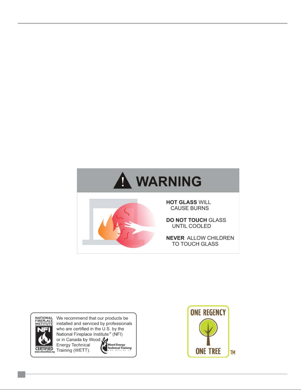
HOT WHILE IN OPERATION DO NOT TOUCH. KEEP CHILDREN,
CLOTHING AND FURNITURE AWAY. CONTACT MAY CAUSE
SKIN BURNS. READ NAMEPLATE AND INSTRUCTIONS.
DO NOT REMOVE THIS LABEL
254
CERTIFIED TO COMPLY WITH JULY 1990
PARTICULATE EMISSION STANDARDS.
UNITED STATES ENVIRONMENTAL
PROTECTION AGENCY
MADE IN CANADA
JAN FEB MAR APR MAY JUN JUL AUG SEPT OCT NOV DEC
CAUTION
DATE OF MANUFACTURE
918-216b
LISTED SPACE HEATER, SOLID FUEL TYPE, ALSO
SUITABLE FOR MOBILE HOME INSTALLATION
MODEL: HAMPTON CAST FREESTANDING WOOD STOVE - H300
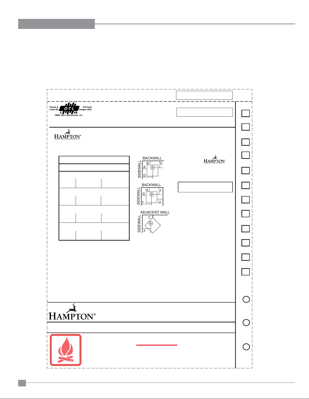
TESTED TO: UL-1482, ULC-S627-00 REPORT NO: 219-S-04-2
MINIMUM CLEARANCES TO
COMBUSTIBLE MATERIALS
RESIDENTIAL INSTALLATION USING
SINGLE WALL CONNECTOR
SIDEWALL A 431 mm / 17 in D 762 mm / 30 in
BACKWALL B 381 mm / 15 in E 381 mm / 15 in
CORNER C 330 mm / 13 in F 483 mm / 19 in
INSTALLATION USING LISTED DOUBLE WALL
CONNECTOR - ALCOVE
INSTALLATION USING LISTED DOUBLE WALL
CONNECTOR - MOBILE HOME
SIDEWALL A 381 mm / 15 in D 711 mm / 28 in
BACKWALL B 254 mm / 10 in E 254 mm / 10 in
CORNER C 228 mm / 9 in F 381 mm / 15 in
SIDEWALL A 381 mm / 15 in D 711 mm / 28 in
BACKWALL B 254 mm / 10 in E 254 mm / 10 in
CORNER C 228 mm / 9 in F 381 mm / 15 in
INSTALLATION USING LISTED DOUBLE WALL
CONNECTOR - RESIDENTIAL CLOSE CLEARANCE
MINIMUM ALCOVE CEILING HEIGHT: 1.5 M / 5 FT MAXIMUM ALCOVE DEPTH 1220 MM / 48 IN.
MINIMUM CLEARANCES FOR HORIZONTAL CONNECTOR TO CEILING: 457 MM / 18"
THE SPACE BENEATH THE HEATER MUST NOT BE OBSTRUCTED. OPERATE ONLY WITH FIREBRICKS IN PLACE.
FLOOR
PROTECTION*
INSTALL AND USE ONLY IN ACCORDANCE WITH THE MANUFACTURER'S INSTALLATION AND OPERATING INSTRUCTIONS.
CONTACT LOCAL BUILDING OR FIRE OFFICIALS ABOUT RESTRICTIONS AND INSTALLATION INSPECTION IN YOUR
AREA. USE 150 MM (6 IN.) DIAMETER MINIMUM 24 MSG BLACK OR 26 MSG BLUED STEEL CONNECTOR WITH LISTED
UL103 HT FACTORY-BUILT CHIMNEY SUITABLE FOR USE WITH SOLID FUELS OR MASONRY CHIMNEY.
SEE LOCAL BUILDING CODE AND MANUFACTURER'S INSTRUCTIONS FOR PRECAUTIONS REQUIRED FOR PASSING A
CHIMNEY THROUGH A COMBUSTIBLE WALL OR CEILING. DO NOT PASS CHIMNEY CONNECTOR THROUGH COMBUSTIBLE
WALL OR CEILING. DO NOT CONNECT THIS UNIT TO A CHIMNEY FLUE SERVING ANOTHER APPLIANCE.
FOR USE WITH SOLID WOOD FUEL ONLY. USE OF OTHER FUELS MAY DAMAGE HEATER AND CREATE A HAZARDOUS CONDITION. DO NOT OBSTRUCT
COMBUSTION AIR OPENINGS. OPERATE ONLY WITH FIREBRICKS IN PLACE. OPERATE ONLY WITH DOOR CLOSED - OPEN FEED DOOR TO FEED FIRE
ONLY. DO NOT USE GRATE OR ELEVATE FIRE. BUILD WOOD FIRE DIRECTLY ON HEARTH. DO NOT OVERFIRE - IF HEATER OR CHIMNEY CONNECTOR
GLOWS YOU ARE OVERFIRING. INSPECT AND CLEAN CHIMNEY AND CONNECTOR FREQUENTLY. UNDER CERTAIN CONDITIONS OF USE CREOSOTE
BUILDUP MAY OCCUR RAPIDLY. KEEP FURNISHINGS AND OTHER COMBUSTIBLE MATERIAL AWAY FROM HEATER. REPLACE GLASS ONLY WITH
NEOCERAM GLASS. COMBUSTIBLE FLOOR MUST BE PROTECTED BY NON-COMBUSTIBLE MATERIAL EXTENDING BENEATH THE HEATER AND TO
THE FRONT AND SIDES AS INDICATED OR TO THE NEAREST PERMITTED COMBUSTIBLE MATERIAL.
OPTIONAL COMPONENT: FAN (846-515), ELECTRICAL RATING: VOLTS 115, 60 HZ, 2 AMPS, SHORT LEGS (200-931, 200-935)
DANGER: RISK OF ELECTRIC SHOCK. DISCONNECT POWER BEFORE SERVICING UNIT. DO NOT ROUTE POWER CORD UNDER OR IN FRONT OF
APPLIANCE.
COMPONENTS REQUIRED FOR MOBILE HOME INSTALLATION: OUTSIDE AIR KIT AND ONE OF THE FOLLOWING DOUBLE WALL CONNECTOR
IN CANADA: LISTED SECURITY MODEL DP, OR OLIVER MACLEOD PRO-VENT PV DOUBLE WALLED CONNECTOR WITH LISTED CHIMNEY SYSTEM:
SECURITY MODEL S2100, ICC EXCEL 2100.
IN USA: LISTED DOUBLE WALL CONNECTORS SECURITY MODEL DP, SELKIRK MODEL DS, OLIVER MACLEOD PRO VENT PV, SIMPSON DURA VENT
MODEL DVL, GSW SUPER PIPE 6, METAL-FAB DOUBLE WALL. CONNECTED TO ONE OF THE FOLLOWING COMPATIBLE CHIMNEY SYSTEMS SECURITY
MODEL S2100 OR MODEL ASHT, SELKIRK MODEL SSII, OLIVER MACLEOD PRO JET 3103, SIMPSON DURA PLUS, GSW MODEL SC OR METAL-FAB
TEMP/GUARD, AMERI-TECHS, ICC EXCEL 2100 . USE CHIMNEY COMPONENTS AS SPECIFIED IN INSTALLATION INSTRUCTIONS.
MEASURE FLUE
FROM HEATER CENTER-LINE
MANUFACTURED BY:
FPI FIREPLACE PRODUCTS INTERNATIONAL LTD.
6988 VENTURE ST.
DELTA, BC V4G 1H4
SIDEWALL G 381 mm / 15 in I 711 mm / 28 in
BACKWALL H 330 mm / 13 in J 330 mm / 13 in
2010 20122011
254
* In Canada, fl oor protection must extend 18"
(457mm) to the front and 8" (200mm) to each
side and back of the stove.
K 457 mm / 18 in
L 150 mm / 6 in
M 150 mm / 6 in
IF SIDE LOAD DOOR IS USED:
Floor protection must extend 18" (457mm) from
the side of the unit to the wall.
Floor protection must be a minimum of 3/8" thick
with a minimum k factor of 0.84.
Minimum clearance with side load door in use is
18" (457mm) to side wall or refer to dimension
(A) if side load door is not used.
This is a copy of the label that accompanies
each Hampton H300 Freestanding Woodstove.
We have printed a copy of the contents here
for your review.
NOTE: Hampton units are constantly being
improved. Check the label on the unit and if
there is a difference, the label on the unit is the
correct one.
COPY OF SAFETY LABEL FOR H300
4
Hampton H300 Cast Freestanding Woodstove
Page 5
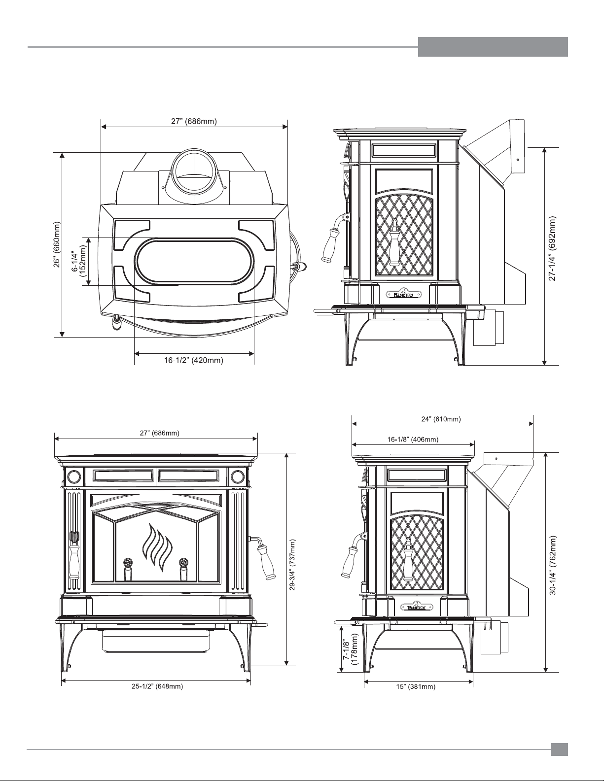
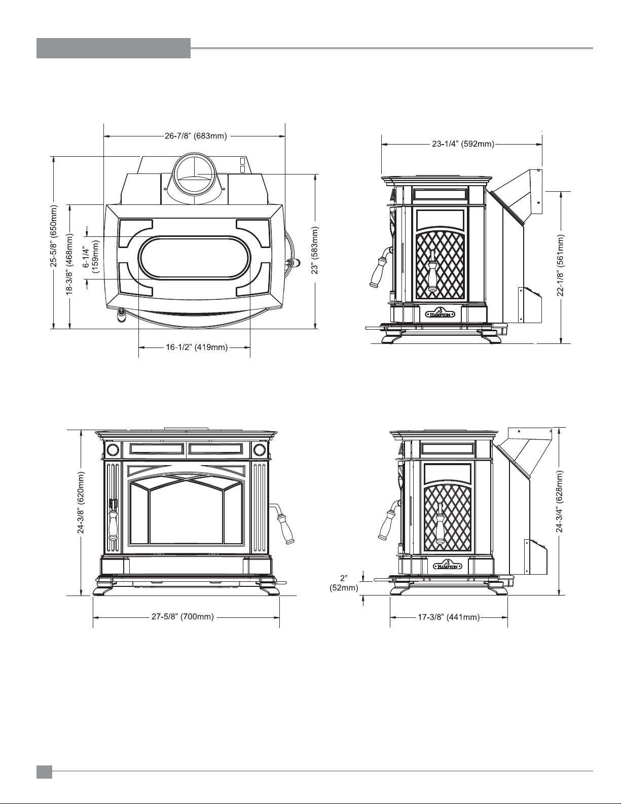
UNIT DIMENSIONS WITH STANDARD LEGS
DIMENSIONS
Hampton H300 Cast Freestanding Woodstove
5
Page 6
DIMENSIONS
UNIT DIMENSIONS WITH OPTIONAL SHORT LEGS
6
Hampton H300 Cast Freestanding Woodstove
Page 7
INSTALLATION
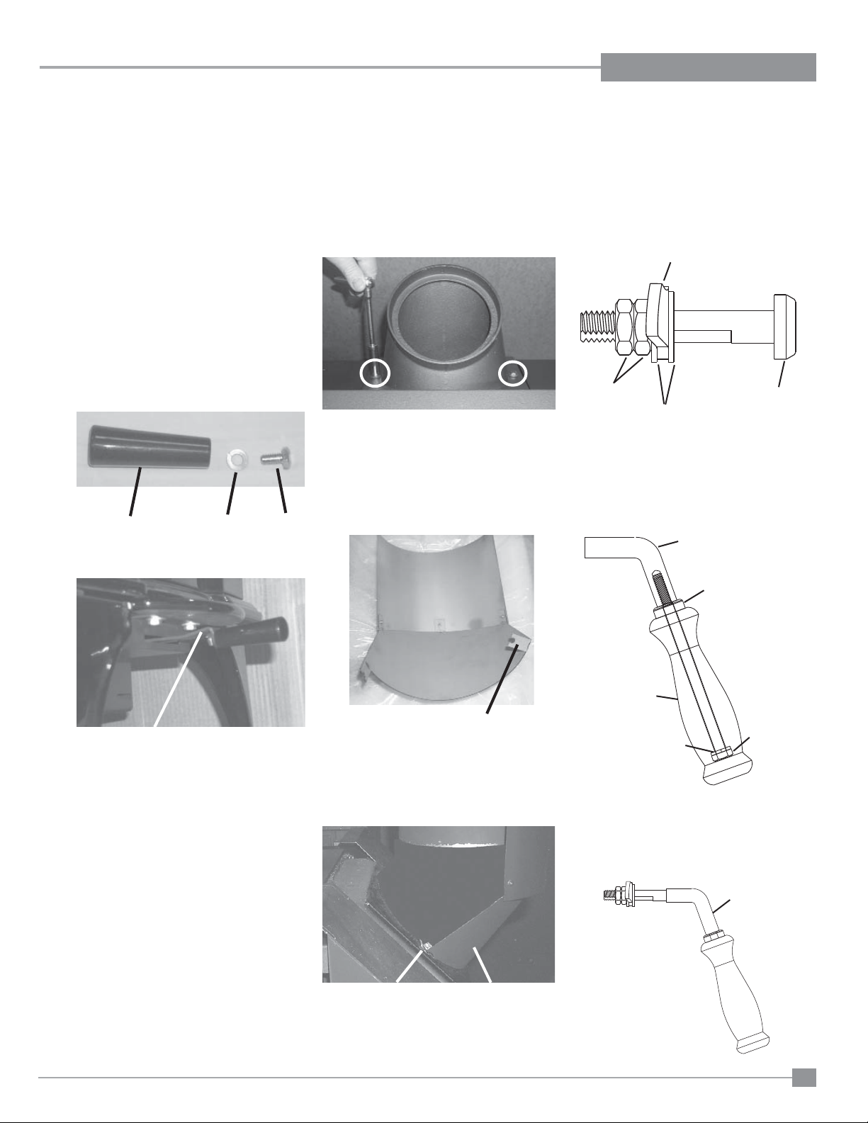
PRE-INSTALLATION
ASSEMBLY
After removing the stove from its packing, open
the front door and remove the contents from the
fi rebox, leaving the bricks in place.
Draft Control
Lever Handle
1) Insert bolt and lock washer through draft
control lever hole.
2) Place handle through bolt. Tighten to se-
cure.
Handle
Washer
Bolt
Rotating Elbow
This stove can be connected to either a top or
rear vent exit by simply reversing the orientation
of the elbow.
Simply remove the 2 screws, change the position of the elbow as desired and secure in place
with screws.
Rear Heat Shield
1) Loosen the bolts that secure the elbow to
the unit. Ensure elbow does not fall off.
2) Bend the tabs on the rear heat shield inwards
90 degrees.
Side Load
Door Handle
1) To install side door handle, remove side
door plug assembly.
Side Door Plug Assembly
Door Latch Bar
Hex Nuts
Flat Washers
2) Assemble handle by:
a) Placing lock washer over hex head bolt.
b) Place hex head bolt into handle.
c) Place spacer over hex head bolt
threads.
d) Screw handle into side door latch.
Latch
Side Door
Plug
Draft Control Lever
Bend tabs inwards 90 degrees.
3) Slide the tabs on the rear heat shield in
between the bolt and washer.
Please Note: The shield needs to be stretched/
fl exed in order to fi t in place.
Slide tabs in between
washer and bolt.
4) Once rear heat shield is evenly in place,
tighten bolts to secure.
Rear Heat Shield
Spacer
Handle
Lock
Washer
3) Place side door handle latch through side
door hole.
4) Re-assemble side door plug assembly to
secure.
Side Door
Plug Assembly
Hex Head
Bolt
Latch
Hampton H300 Cast Freestanding Woodstove
7
Page 8
INSTALLATION
RESIDENTIAL
INSTALLATION
1) Please read this entire manual before you
install and use your new woodstove. Failure
to follow instructions may result in property
damage, bodily injury or even death. Be
aware that local Codes and Regulations
may override some items in this manual.
Check with your local inspector.
2) Select a position for your Hampton Stove.
Consult the minimum clearance chart for
your model and set the stove in place. For
close clearance installation use listed double
wall connector systems.
3) To insure vertical alignment, suspend a
plumb bob from the ceiling over the exact
center of your stove fl ue and mark a spot
on the ceiling to indicate the center of the
chimney.
4) Check that the area above the ceiling is
clear for cutting. Re-confi rm the clearance
from the stove to combustibles to insure that
they are within the prescribed limits.
5) This woodstove must be connected to a
UL 103 HT (ULC S629) listed chimney or
a code approved masonry chimney with a
fl ue liner.
6) Install chimney according to chimney manu-
facturers instructions. The performance of
your woodstove is governed to a very large
part by the chimney system. Too short a
chimney can cause diffi cult start-up, dirty
glass, backsmoking when door is open, and
even reduced heat output. Too tall a chimney
may prompt excessive draft which can result
in very short burn times and excessive heat
output. The use of an inexpensive fl ue pipe
damper may be helpful in reducing excessive
draft.
CAUTION: The chimney should be the same
size as the 6" (152mm) fl ue outlet on the
stove. The chimney must be listed as suitable for use with solid fuels. For other types
of chimneys check with your local building
code offi cials. Do not confuse a chimney
with a type “B” Venting System used for gas
appliances as suitable for a wood burning
appliance (refer to the Mobile Home installations section).
7) Mark the location of the legs on the fl oor,
then move the stove aside and mark the
position of the fl oor protector.
8) The fl oor protector must be of non-combus-
tible material and must extend 18" (457mm)
in front of the door opening and 6" (152mm)
to the sides and rear of the unit. Some areas
may require a larger size fl oor protector.
Refer to the Mobile Home Installation section for outside air installation instructions
and see your local inspector.
NOTE: In Canada, fl oor protection must ex-
tend 18" (450mm) to the front and 8" (200mm)
to each side and back of the stove.
9) When the fl oor protection is complete, posi-
tion the stove with the fl ue collar centered
under the installed chimney.
10) In seismically active areas, we recommend
that your unit is secured to the fl oor by using
the bolt down holes inside the legs (the same
ones used in Mobile Home installations).
11) For residential installations using 6"
(152mm) "C" Vent (single wall) the chimney
connector must be at least 24 gauge steel.
Do not use galvanized pipe (refer to the
Mobile Home installation section).
12) Do not connect this unit to a chimney
serving another appliance.
13) A chimney connector cannot pass through
an attic or roof space, closet or similar
concealed space, or a fl oor, ceiling, wall
or partition of combustible construction.
In Canada, if passage through a wall, or
partition of combustible construction is
desired, the installation shall conform to
CAN/CSA-B365, Installation Code for SolidFuel-Burning Appliances and Equipment.
14) Your Hampton Woodstove is not to be connected to any air distribution duct.
Emissions from burning wood or gas could
contain chemicals known to the State of
California to cause cancer, birth defects
or other reproductive harm.
MODULAR INSTALLATION OPTIONS
OPTIONS: These can be installed at time of installation or added later:
Modular Option
Blower/Fan
Side Load Door
Outside Air
Adaptor
Side Shelves
Short legs
8
Adding the blower will increase the area heated by the stove, it can move warm air beyond the room where the stove
is installed (refer to the Optional Blower / Fan Installation section).
The side load door allows for putting in larger logs into the fi re easier ( refer to Side Load Door section).
Helps combustion in small or poorly ventilated houses. Installation instructions come with adaptor.
Add to the traditional look of the stove and double as a warming area for your cookstove creations.
Helps in reducing the overall height of the unit to accomodate a variety of installations. Using this option prohibits the
use of the ash drawer.
Things to consider when choosing options
Hampton H300 Cast Freestanding Woodstove
Page 9
INSTALLATION
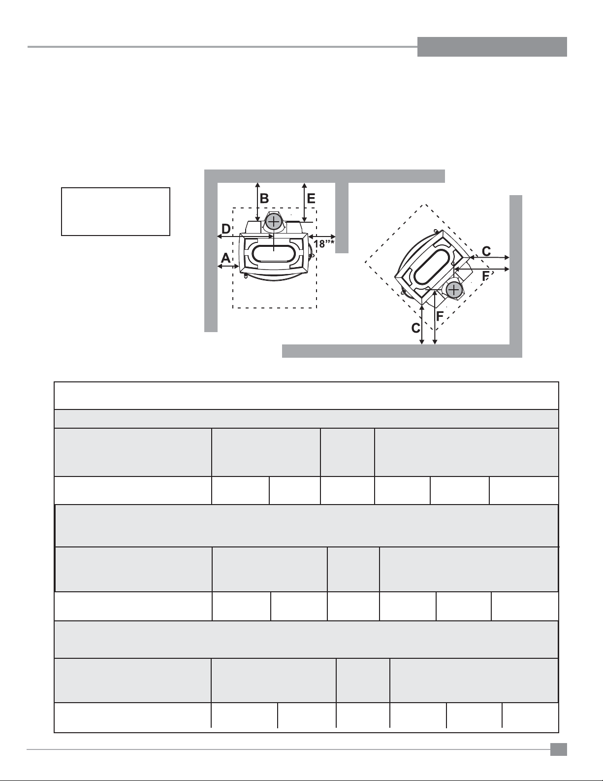
MINIMUM CLEARANCE TO
COMBUSTIBLE MATERIALS
Please read the section below carefully. Measurements "From Unit" are from the top plate of the stove to a side wall or to a corner, and from the
rear heat shield to a back wall.
Clearances may only be reduced by means approved by the regulatory authority.
* Minimum clearance with
side load door in use is 18"
(457mm) to side wall or refer
to dimension (A) if side load
door is not used.
NOTE: Be aware that local Codes and Regulations may override some clearances listed in this manual.
Check with your local inspector.
Residential Installation “C” Vent (Single Wall)
Unit (with Heat Shield) From Unit From From Flue Center-Line
Corner
A B C D E F
H300 17" (431 mm) 15" (381 mm) 13" (330 mm) 30" (762 mm) 15" (381 mm) 19" (483 mm)
Residential Close Clearance (To be installed with required pipe components)
When the stove is installed as a close clearance residential unit, a listed double wall connector is required from the stove collar to the ceiling
level.
Unit (with Heat Shield) From Unit From From Flue Center-Line
Corner
A B C D E F
H300 15" (381 mm) 10" (254 mm) 9" (228 mm) 28" (711 mm) 10" (254 mm) 15" (381 mm)
Mobile Home Close Clearance (To be installed with required pipe components)
"C" Vent single wall pipe is not approved for Mobile Home installations. (Refer to Mobile Home section).
Unit (with Heat Shield) From Unit From From Flue Center-Line
Corner
A B C D E F
H300 15" (381 mm) 10" (254 mm) 9" (228 mm) 28" (711 mm) 10" (254 mm) 15" (381 mm)
Hampton H300 Cast Freestanding Woodstove
9
Page 10
INSTALLATION
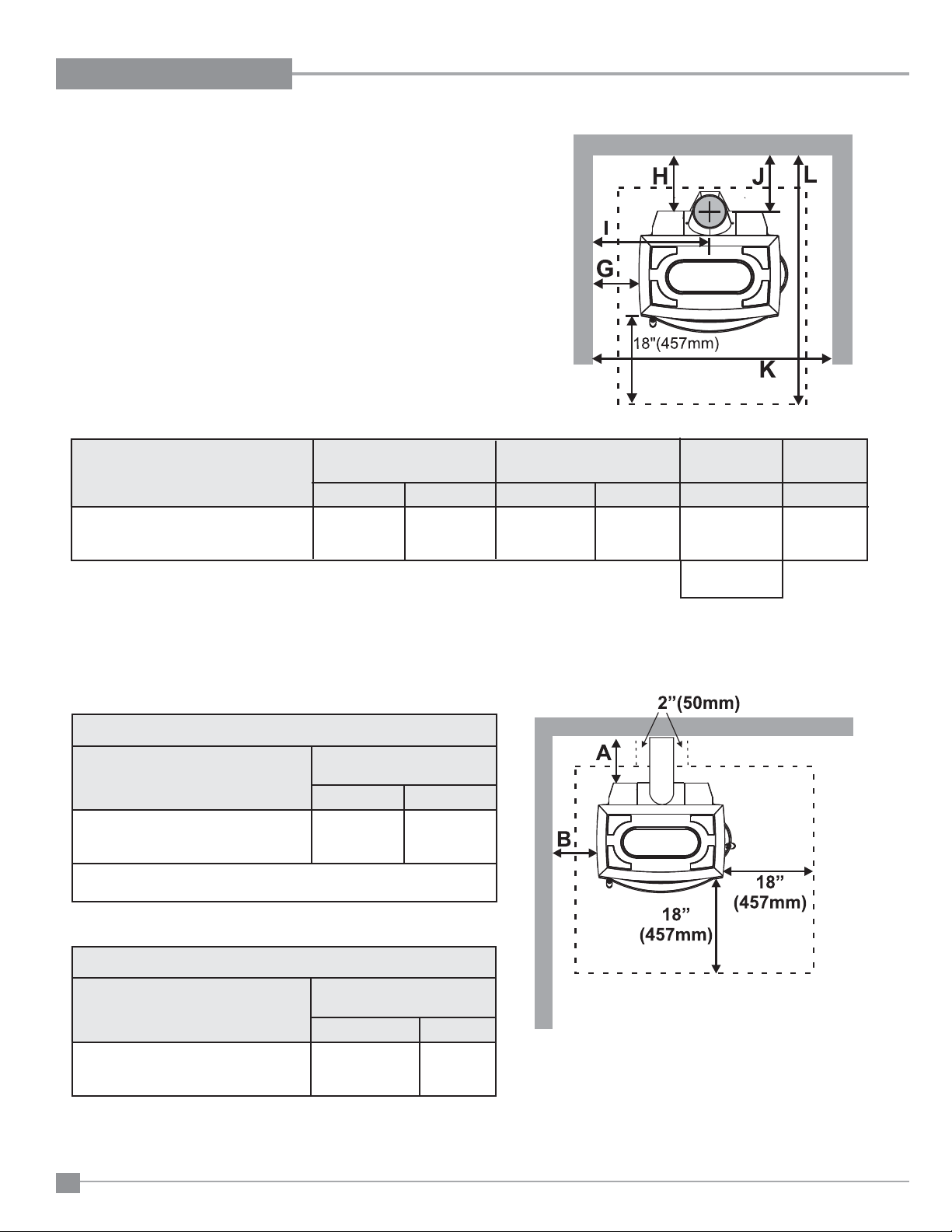
MINIMUM ALCOVE CLEARANCE TO
COMBUSTIBLE MATERIALS
This Hampton Freestanding model has been alcove approved and must be installed
with a listed double wall connector to the ceiling level.
Note: Minimum alcove ceiling height (from fi nished fl oor) - 60" (1525 mm)
Maximum depth of alcove - 48" (1220 mm)
From From Flue Min. Min.Hearth
Unit (with Heat Shield) Unit Center-line Width to Rear Wall
G H I J K L
H300 15" (381 mm) 13" (330 mm) 28" (711 mm) 13" (330 mm) 57" (1448 mm) 51-1/4"
without side load door (1301 mm)
60" (1524 mm)
with side load door
ADDITIONAL CLEARANCES
FOR BACKWALL EXIT
Minimum Clearance to Combustibles
From
Unit (with Heat Shield) Unit
A B
H300 9" (228 mm) 15" (381 mm)
Min. Mantel Height (from fi nished fl oor): 48" 1219 mm
Max. Mantel Depth: 12" 305 mm
Minimum Clearance to Non-Combustibles
From
Unit (with Heat Shield) Unit
A B
H300 min. 0" (0 mm) 15" (381mm)
max. 9" (228 mm)
10
Note: Floor Protection must extend 2" (50mm)
to each side of the elbow.
Note: If side load door is used, fl oor protection
must extend at least 18" (457mm) from
the side of the unit.
Hampton H300 Cast Freestanding Woodstove
Page 11
INSTALLATION
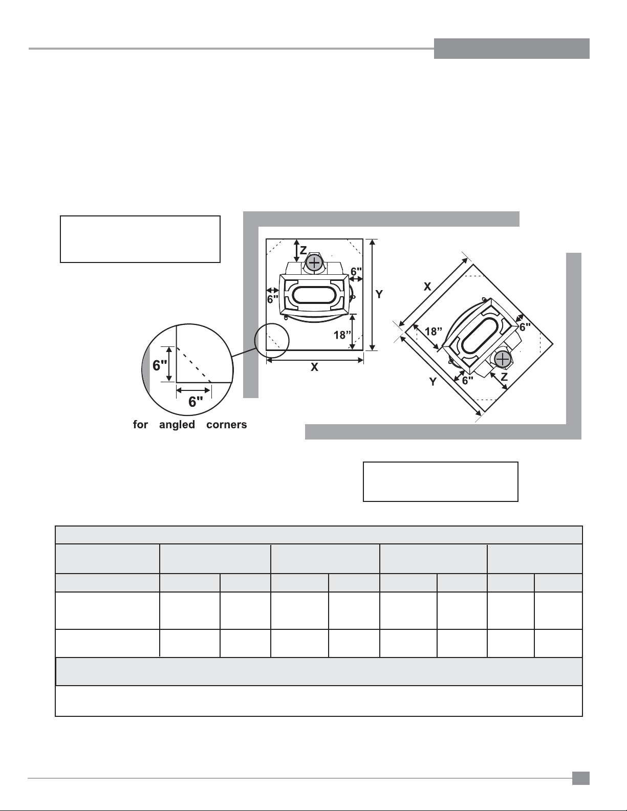
FLOOR PROTECTION
A combustible fl oor must be protected by non-combustible material (like tile, concrete board, or certifi ed to UL-1618 or as defi ned by local codes)
extending beneath the heater and a minimum of 6" from each side and minimum 18" from the front face of the stove and minimum 6" (or the rear
clearance to combustibles whichever is smaller) from the rear of the stove.
When installed with horizontal venting, non-combustible fl oor protection must beneath the fl ue pipe and extend 2" (51mm) beyond each side.
A minimum of a 1/2" thick thermal fl oor protector with a 0.75k factor is required when installing the standard or optional short legs. This applies to
both Canada and the US. All other requirements (ie. hearth size) remain the same.
IF SIDE LOAD DOOR IS USED:
Floor protection must extend 18" (457mm)
from the side of the unit to the wall.
NOTE: In Canada, fl oor protection must
extend 18" (450mm) to the front
and 8" (200mm) to each side and
back of the stove.
Minimum Overall Depth (Y) of Floor Protector
Residential Residential Mobile Home Alcove
Unit "C" Vent Close Clearance Close Clearance
Y Z Y Z Y Z Y Z
H300 (US) 44-1/2" 6" (152 mm) 44-1/2" 6" (152 mm) 44-1/2" 6" (152 mm) 44-1/2" 6" (152 mm)
(1130 mm) (1130 mm) (1130 mm) (1130 mm)
H300 (Canada) 46-1/2" 8" (203 mm) 46-1/2" 8" (203 mm) 46-1/2" 8" (203 mm) 46-1/2" 8" (203 mm)
(1181 mm) (1181 mm) (1181 mm) (1181 mm)
Minimum Overall Width (X) of Floor Protector for all installations:
H300 39" (990 mm) - US
43" (1092mm) - Canada
Hampton H300 Cast Freestanding Woodstove
11
Page 12

INSTALLATION
HOW TO DETERMINE IF
ALTERNATE
FLOOR PROTECTION
MA TERIALS ARE
ACCEPTABLE
The specifi ed fl oor protector should be 3/8"
(18mm) thick material with a K - factor of
0.84.
The proposed alternative is 4" (100mm) brick
with a C-factor of 1.25 over 1/8" (3mm) mineral
board with a K-factor of 0.29.
Step (a):
Use formula above to convert specifi cation
to R-value.
R = 1/k x T = 1/0.84 x .75 = 0.893.
Step (b):
Calculate R of proposed system.
4" brick of C = 1.25, therefore
Rbrick = 1/C = 1/1.25 = 0.80
1/8" mineral board of k = 0.29, therefore
Rmin.bd. = 1/0.29 x 0.125 = 0.431
Total R = Rbrick + Rmineral board =
0.8 + 0.431 = 1.231.
Step (c):
Compare proposed system R of 1.231 to
specifi ed R of 0.893. Since proposed system
R is greater than required, the system is
acceptable.
DEFINITIONS
Thermal Conductance:
C = Btu = W
(hr)(ft
Thermal Conductivity:
k = (Btu)(inch) = W = Btu
(hr)(ft3)(oF) (m)(K) (hr)(ft)(oF)
Thermal Resistance:
R = (ft2)(hr)(oF) = (m2)(K)
Btu W
2 )(o
F) (m2))(K)
STEP-BY-STEP
CHIMNEY AND
CONNECTOR
INSTALLATION
Note: These are a generic set of chimney
installation instructions. Always follow the manufacturers own instructions explicitly. Check the Minimum
Recommended Flue Heights (Table
1).
1) With your location already established, cut
and frame the roof hole. It is recommended
that no ceiling support member be cut for
chimney and support box installation. If it is
necessary to cut them, the members must
be made structurally sound.
2) Install radiant shield and support from
above.
3) Stack the insulated pipe onto your fi nish
support to a minimum height of 3 feet above
the roof penetration, or 2 feet above any
point within 10 feet measured horizontally.
There must be at least 3 feet of chimney
above the roof level.
Note: Increasing the chimney height above
this minimum level will sometimes
help your unit to “breathe” better
by allowing a greater draft to be created. This greater draft can decrease
problems such as, diffi cult start-ups,
back-smoking when door is open,
and dirty glass. It might be suffi cient
to initially try with the minimum required height, and then if problems
do arise add additional height at a
later date.
4) Slide the roof fl ashing over your chimney
and seal the fl ashing to the roof with roofi ng
compound. Secure the fl ashing to your roof
with nails or screws.
5) Place the storm collar over the fl ashing,
sealing the joints with a silicone caulking.
6) Fasten the raincap with spark screens (if
required) to the top of your chimney.
7) For optimum effi ciency when installing into
a masonry chimney, size accordingly, i.e.
the 6" (152mm) fl ue dia. is 28.28 sq.in.
8) To complete your chimney installation, install
the double wall connector pipe from the
stove’s fl ue collar to the chimney support
device.
9) If you are using a horizontal connector,
the chimney connector should be as high
as possible while still maintaining the 18"
(457mm) minimum distance from the horizontal connector to the ceiling.
10) NOTE: Residential Close Clearance and
Alcove installations require a listed double wall connector from the stove collar
to the ceiling level.
The diagrams below illustrate one way to install your unit into a standard ceiling or with a
horizontal connector. Check with your dealer
or installer for information on other options
available to you.
Standard Ceiling Installation
Horizontal Installation
FACTORY
BUILT CHIMNEY
When a metal prefabricated chimney is used, the
manufacturer's installation instructions must be
followed. You must also purchase and install the
ceiling support package or wall pass-through and
"T" section package, fi restops (where needed),
insulation shield, roof fl ashing, chimney cap,
etc. Maintain proper clearance to the structure
as recommended by the manufacturer. The
chimney must be the required height above the
roof or other obstructions for safety and proper
draft operation.
12
Hampton H300 Cast Freestanding Woodstove
Page 13

MASONRY
CHIMNEY
Ensure that a masonry chimney meets the minimum
standards of the National Fire Protection Association
(NFPA) by having it inspected by a professional.
Make sure there are no cracks, loose mortar or
other signs of deterioration and blockage. Have
the chimney cleaned before the stove is installed
and operated. When connecting the stove through
a combustible wall to a masonry chimney, special
methods are needed (refer to the Combustible Wall
Chimney Connector Pass-Throughs section).
INSTALLATION
MASONRY
FIREPLACE
There are listed kits available to connect a stove
to a masonry fi replace. The kit is an adapter that
is installed at the location of the fi replace damper.
The existing damper may have to be removed to
allow installation.
Hampton H300 Cast Freestanding Woodstove
13
Page 14

INSTALLATION
COMBUSTIBLE WALL CHIMNEY
CONNECTOR PASS-THROUGHS
Method A: 12" (304.8 mm) Clearance to Combustible Wall
Member:
Using a minimum thickness 3.5" (89 mm) brick and a 5/8" (15.9 mm)
minimum wall thickness clay liner, construct a wall pass-through.
The clay liner must conform to ASTM C315 (Standard Specifi cation
for Clay Fire Linings) or its equivalent. Keep a minimum of 12" (304.8
mm) of brick masonry between the clay liner and wall combustibles.
The clay liner shall run from the brick masonry outer surface to the
inner surface of the chimney fl ue liner but not past the inner surface.
Firmly grout or cement the clay liner in place to the chimney fl ue liner.
Method B: 9" (228.6 mm) Clearance to Combustible Wall Member:
Using a 6" (152.4 mm) inside diameter, listed, factory-built Solid-Pak
chimney section with insulation of 1" (25.4 mm) or more, build a wall
pass-through with a minimum 9" (228.6 mm) air space between the
outer wall of the chimney length and wall combustibles. Use sheet
metal supports fastened securely to wall surfaces on all sides, to
maintain the 9" (228.6 mm) air space. When fastening supports to
chimney length, do not penetrate the chimney liner (the inside wall
of the Solid-Pak chimney). The inner end of the Solid-Pak chimney
section shall be fl ush with the inside of the masonry chimney fl ue, and
sealed with a non-water soluble refractory cement. Use this cement
to also seal to the brick masonry penetration.
Minimum
12 in. (304.8mm)
to combustibles
Minimum chimney clearance to brick
and combustibles 2 in. (50.8mm)
Minimum clearance
12 in. (304.8mm)
of brick
Chimney
Chimney Flue
Masonry chimney
connector
Fire clay
liner
Method C: 6" (152.4 mm) Clearance to Combustible Wall Member:
Starting with a minimum 24 gage (.024" [.61 mm]) 6" (152.4 mm) metal
chimney connector, and a minimum 24 gage ventilated wall thimble
which has two air channels of 1" (25.4 mm) each, construct a wall
pass-through. There shall be a minimum 6" (152.4) mm separation area
containing fi berglass insulation, from the outer surface of the wall thimble
to wall combustibles. Support the wall thimble, and cover its opening
with a 24-gage minimum sheet metal support. Maintain the 6" (152.4
mm) space. There should also be a support sized to fi t and hold the
metal chimney connector. See that the supports are fastened securely
to wall surfaces on all sides. Make sure fasteners used to secure the
metal chimney connector do not penetrate chimney fl ue liner.
Method D: 2" (50.8 mm) Clearance to Combustible Wall Member:
Start with a solid-pak listed factory built chimney section at least
12" (304 mm) long, with insulation of 1" (25.4 mm) or more, and an
inside diameter of 8" (2 inches [51 mm] larger than the 6" [152.4
mm] chimney connector). Use this as a pass-through for a minimum
24-gage single wall steel chimney connector. Keep solid-pak section
concentric with and spaced 1" (25.4 mm) off the chimney connector
by way of sheet metal support plates at both ends of chimney section.
Cover opening with and support chimney section on both sides with
24 gage minimum sheet metal supports. See that the supports are
fastened securely to wall surfaces on all sides. Make sure fasteners
used to secure chimney fl ue liner.
14
Hampton H300 Cast Freestanding Woodstove
Page 15

RECOMMENDED HEIGHTS FOR
WOODSTOVE FLUE
INSTALLATION
Simple rules on draft. See Table 1.
1) At sea level minimum height is 12'
straight.
2) Add the following vertical height to compen-
sate for:
45 deg. elbow = 1 ft.
90 deg. elbow = 2 ft.
"T" = 3 ft.
Each foot of horizontal run = 2 ft.
3) Add 4% overall for each 1000' above sea
level.
TABLE 1
MINIMUM RECOMMENDED FLUE HEIGHTS IN FEET
# OF ELBOWS
ELEVATION (FT)
ABOVE SEA LEVEL 0 2 x 15
0-1000 12.0 13.0 14.0 15.0 18.0 16.0 20.0
1000-2000 12.5 13.5 14.5 15.5 19.0 16.5 21.0
2000-3000 13.0 14.0 15.0 16.0 19.5 17.0 21.5
3000-4000 13.5 14.5 15.5 17.0 20.0 18.0 22.5
4000-5000 14.0 15.0 16.0 17.5 21.0 18.5 23.0
5000-6000 14.5 15.5 17.0 18.0 21.5 19.0 24.0
6000-7000 15.0 16.0 17.5 18.5 22.5 20.0 25.0
7000-8000 15.5 16.5 18.0 19.0 23.0 20.5 25.5
8000-9000 16.0 17.0 18.5 20.0 24.0 21.0 26.5
9000-10000 16.5 17.5 19.0 20.5 24.5 22.0 27.0
Example: a)
1-1/2 ft. of horizontal run = 3 ft.
one "T" = 3 ft.
Total Addition (at sea level) = 6 ft.
Example: b)
One 90 deg. elbow = 2 ft.
2 ft. of horizontal run = 4 ft.
one "T" = 3 ft.
Total Addition (at sea level) = 9 ft.
(Measured from the top of the unit)
o
4 x 15o 2 x 30o 4 x 30o 2 x 45o 4 x 45
Recommended Flue Height
Elevation Example a) Example b)
0' 18' 21'
1000' 18.72' 21.84'
2000' 19.44' 22.68'
5000' 21.60' 25.20'
8000' 23.76' 27.72'
o
NOTE: No more than two offsets (four elbows) allowed. Two 45o elbows equal one 90o elbow.
Hampton H300 Cast Freestanding Woodstove
15
Page 16

INSTALLATION
MOBILE HOME INSTALLATION
Once you have properly marked the position
of your unit and the fl oor protection as outlined
in the Residential Installation items #1 through
#8, a supply of fresh air has to be supplied to
your unit.
Place your unit in position and secure it to the
fl oor using four lag bolts 1/4" through the four
holes inside the legs. It is important to maintain
the structural integrity of the Mobile Home fl oor,
walls and roof when installing your unit.
For Mobile Home units installed in the U.S. the
unit must be grounded using a #8 ground wire
with approved termination and star washer.
CAUTION: At no time use unlabelled
parts, or substitute parts made for another
chimney system.
Install as per chimney manufacturer's
installation instructions.
IMPORTANT
DO NOT CONNECT TO OR USE IN CONJUNCTION WITH ANY AIR DISTRIBUTION
DUCTWORK UNLESS SPECIFICALLY APPROVED FOR SUCH INSTALLATIONS.
If desired, the air for combustion may be drawn
directly from the outside of the house, as detailed
below. It is not obligatory to do this, but it may
help combustion in small or poorly ventilated
house.
Connect a 4" (100 mm) diameter stainless steel,
or other non-combustible corrosion resistant
material, to the O.S.A hook-up box. In order to do
this the O.S.A hook-up box must be connected to
the base using 1/2" (12 mm) hex head bolts.
Run the pipe (up to 54" (1372 mm) long) to the
outside avoiding sharp bends and joints within
cavity walls. Turn the end down and fi t corrosion
resistant mesh to prevent the entry of leaves
and rodents. Seal the penetration of the outside
wall with silicon.
WARNING: Do not obstruct free air supply
to the air inlet duct located at the back of
the stove.
NOTE: Listed factory built chimney connectors including elbows are acceptable
for use in Mobile Home Installations.
In addition to standard installation instructions
the following requirements are mandatory for
installation in a mobile home.
1) The stove must be permanently bolted to
the fl oor of the Mobile Home using the fl oor
screws provided.
2) The stove must have a permanent outside
air source for combustion.
3) The stove must be electrically grounded to
the steel chassis of the Mobile Home.
4) A listed double-wall connector chimney
system, roof thimble, spark arrestor and
roof fl ashing kit suitable for use in Mobile
Homes must be used.
5) If the chimney exits the Mobile Home at a
location other than through the roof, and exits
at a point 7ft. (2130mm) or less above the
ground level on which the Mobile Home is
positioned a guard or method of enclosing
the chimney shall be fi tted at the point of
exit for a height up to 7ft. (2130mm).
6) The chimney shall be attached directly to
the room heater and shall extend at least
3 ft. (914mm) above the part of the roof
through which it passes. The top of the
chimney should project at least 2ft. (610mm)
above the highest elevation of any part of
the Mobile Home within 10 ft. (3048mm) of
the chimney.
7) The chimney system shall comply with Local
Requirements.
8) Any openings in a chimney guard where
required must not permit the entrance of
3/4" (19mm) diameter rod.
9) CAUTION: THE STRUCTURAL INTEGRITY OF THE MOBILE HOME ROOF,
FLOOR, WALLS AND CEILING MUST BE
MAINTAINED.
10) Check any other local building code as other
local codes may apply.
11) WARNING: DO NOT INSTALL IN A SLEEP-
ING ROOM OF A MOBILE HOME.
12) Use silicone to create an effective vapour
barrier at the location where the chimney or
other component penetrates to the exterior
of the structure.
16
Hampton H300 Cast Freestanding Woodstove
Page 17

INSTALLATION
LISTED COMPONENTS
FOR MOBILE HOME INSTALLATION
The Hampton H300 Cast Freestanding unit is approved for installation in a Mobile Home if one of the following pipe systems is used.
U.S. Installation*
METALBESTOS SSII
Qty. Part # Description
1 6DS-VK Connector Kit
1 6TMH Shield/Support
1 6TAF-6 Flashing
1 6T-36 Chimney Length
1 6T-18 Chimney Length
1 6T-CT Rain Cap
PRO-JET 3103
Qty.Part # Description
1 PV06-TK Connector
1 CSB Shield/Support
1 RRS Radiation Shield
1 LFR03 Flashing
1 SL3 Chimney Length
1 SL1 Chimney Length
1 RCSA Rain Cap
SECURITY ASHT
Qty.Part # Description
1 DL42A-6 Connector Kit
1 6SS Shield/Support
1 6FAMH Flashing
1 6L3 Chimney Length
1 6L1 Chimney Length
1 CPE Rain Cap
SECURITY S2100
Qty.Part # Description
1 DL42A-6 Connector Kit
1 6XSF Support
1 6XFA Flashing
1 6XL3 Chimney Length
1 6XL18 Chimney Length
1 6XCPE Rain Cap
AMERI-TECHS
Qty.Part # Description
1 6DCC Connector
1 6HSRS-12 Roof Support (6PLRS-12BK)
1 6F Flashing
1 6HS-36 Chimney Length
1 6HS-18 Chimney Length
1 6HS-RCS Rain Cap (6PL-MPC)
SIMPSON DURA-PLUS
Qty.Part # Description
1 6DVL8693 Connector Kit
1 6DP-MH9096 Mobile Home Kit
ICC EXCEL 2100
Qty.Part # Description
1 6CL48 48" Chimney length (also in
12", 18", 24" lengths.
1 6RC Rain Cap
1 6RCS Spark Screen (for rain cap)
1 6RDS/SQS Round/Square support box
1 6VF Flashing
1 6UBA "Ultrablack" Close Clearance
Connector
Canadian Installations*
SECURITY S2100 (see above for details)
ICC EXCEL 2100 (see above for details)
*The use of alternate pitch fl ashings, support
box extensions, additional chimney lengths,
and additional chimney bracing, may be used
on each of the previously listed systems. These
parts though must be from the same system
as listed, and must be a similar and/or complimentary part.
CAUTION: At no time use unlabelled
parts, or substitute parts made for
another chimney system.
Install as per chimney manufacturer's
installation instructions.
METAL-FAB TEMP/GUARD 2100
Qty.Part # Description
1 6DWBK Connector
1 6TGRS Roof Support
1 6TGG36 Chimney Length
1 6TGG12 Chimney Length
1 6TGF Flashing
1 6TGC Rain Cap
Hampton H300 Cast Freestanding Woodstove
17
Page 18

INSTALLATION
BRICK INSTALLATION
Firebrick is included to extend the life of your
stove and to radiate heat more evenly. Check
to see that all fi rebricks are in their correct
positions and have not become misaligned
during shipping.
DOOR REMOVAL
1) Push spring lever down while holding onto
the door.
2) Pull door down and lift out to remove. Bottom
of door lifts right out.
Spring Lever
GLASS INSTALLATION
1) Remove door from unit.
2) To replace the glass remove the 12 screws
highlighted in the diagram below.
3) Lift off the glass retainer and carefully remove
glass.
4) Place new glass in the door, make sure
that the glass gasketing will properly seal
your unit.
5) Position the glass retainer back on. En-
sure that it rests on the gasket and not the
glass.
6) Secure glass retainer using the 12 screws.
Do not wrench down on the glass as this
may cause the glass to break.
7) Place door back on unit.
Bottom part of door
fi ts into slot.
Remove 12 screws.
Glass Retainer
18
Hampton H300 Cast Freestanding Woodstove
Page 19

OPTIONAL SHORT LEG INSTALLATION
INSTALLATION
1) Remove the cast lid from the top of the stove.
2) Remove fan, if installed.
3) Open the front door and remove the cast plug and all loose bricks
from the fi rebox.
4) Close the front door.
5) Remove the Ash Pan by sliding out and discard.
Ash Pan
8) Flip the cover plate so that the ash plug hole is covered. Secure the
cover plate in place using the 6 bolts and washers removed in step 7.
Cover Plate
Cover Plate shown in it's original position when
Ash Drawer is removed.
6) Carefully lay the stove on it's back on a soft surface to prevent
scratching.
7) Remove the Ash Drawer by undoing the 6 bolts and washers. Discard
Ash Drawer.
Ash Drawer
Cover Plate shown fl ipped and secured in place
covering the Ash Plug Hole.
9) Remove the 4 standard legs by undoing the bolt and washer on
each leg.
Hampton H300 Cast Freestanding Woodstove
19
Page 20

INSTALLATION
10) Secure the 4 short legs to the unit using the bolts and washers
removed from step 9.
Flue center-line dimensions change when using the short leg option.
Also note that the Outside Air Kit (Part # 47000) cannot be used with the short leg option.
11) Carefully bring stove to standing position.
12) Open the front door and place the cast plug into the ash plug hole
and re-install the bricks.
13) Place the cast lid back on top of the stove.
14) Re-install fan, if removed.
IMPORTANT
20
Hampton H300 Cast Freestanding Woodstove
Page 21

OPTIONAL BLOWER / FAN INSTALLATION
An optional blower is available for the Hampton
H300. The blower is factory assembled, wired
and ready for attachment to the stove.
This unit must be connected to a grounded,
standard 120 volts, 60 Hz electrical outlet.
Never route the power cord under or in front
of the unit.
1) Lift off top.
2) Place left and right side air channels on
fi rebox top as shown below.
INSTALLATION
5) Remove fan cover plate from back shield
by undoing 3 screws.
Do not under any circumstances, cut or remove
the grounding prong from the power cord. Do
not use an adaptor plug.
NOTE: For more detailed information see
instructions included with the Optional
Blower.
CAUTION: Moving parts may cause injury.
Do not operate unit with blower housing
removed.
DANGER: Risk of electric shock. Disconnect power before servicing unit.
WARNING: Electrical Grounding
Instructions
This appliance is equipped with
a three pronged (grounding) plug
for your protection against shock
hazard and should be plugged
directly into a properly grounded
three-prong receptacle. Do not cut
or remove the grounding prong
from this plug.
Screws
Left Side
Air Channel
3) Secure each air channel with one screw.
Right Side
Air Channel
Shown
with screw.
4) Remove back shield by undoing 2 screws.
Right Side
Air Channel
Secure
6) Loosen the 2 bolts you see after removing
the fan cover plate. One on each side of
unit.
Right Side
Bolt
7) Hook fan over bolts.
8) Tighten bolts to secure fan.
9) Reinstall back shield.
10) Using the 3 screws from the fan cover
plate, secure the fan assembly to the back
shield.
Neutral
120 AC
NOTE INPUT POWER: Australia, New Zealand,
China and Japan use 240V AC 50 Hz.
Live
60 Hz
Fan Thermodisc
normallyopen
round
reen
lack lack
lack
Blower/Fan Wiring Diagram
Hampton H300 Cast Freestanding Woodstove
anual
Auto
Switch
Fan
Switch
Low Red
High lack
Fan Fan
11) Plug-in power cord.
12) Place top back on.
White
CAUTION: Label all wires
prior to disconnection
when servicing controls.
Wiring errors can cause
improper and dangerous
operation.
round
21
Page 22

INSTALLATION
SIDE SHELF
INSTALLATION
1) Secure the two support gussets using 2 screws per gusset and attach
bracket to the underside of the shelf using 2 screws as shown.
Support
Gussets
Bracket
2) Remove stove top and place side shelf onto the side of the stove as
shown, aligning the bracket with notch at the side of the stove.
3) Secure to side shelf to stove. Repeat installation for other side.
4) Carefully re-install stove top on stove ensuring not to chip enamel.
22
5) Use the two screws holding the bracket to the underside of the shelf
to make fi nal alignment and adjustments.
Hampton H300 Cast Freestanding Woodstove
Page 23

OPERATING INSTRUCTIONS
INSTALLATION
OPERATING
INSTRUCTIONS
With your unit now correctly installed and safety
inspected by your local authority, you are now
ready to start a fi re. Before establishing your
fi rst fi re, it is important that you fully understand
the operation of your draft control (refer to Draft
Control section).
FAN OPERATION
Automatic
To operate the optional fan automatically, push
the bottom switch on the side of the fan housing
to "AUTO" and the top switch to either "HIGH"
or "LOW" for fan speed.
This will allow the fan to turn on as the stove
has come up to operating temperature. It will
also shut the fan system off after the fi re has
gone out and the unit cooled to below a useful
heat output range.
Manual
To manually operate the fan system push the bottom switch to "MAN" and the top switch to either
"HIGH" or "LOW". This will bypass the sensing
device and allow full control of the fan.
Switching from "AUTO" to "MAN" or "HIGH" to
"LOW" may be done anytime.
FIRST FIRE
When your installation is completed and inspected you are ready for your fi rst fi re.
1) Open control fully.
2) Open fi rebox door and build a small fi re us-
ing paper and dry kindling on the fi rebrick
hearth. Secure door on the fi rebox and wait
a few minutes for a good updraft in the fl ue to
establish the fi re. (Leaving the door slightly
open will help your fi re start more rapidly.)
CAUTION: Never leave unit unat-
tended if door is left open. This
procedure is for fi re start-up only,
as unit may overheat if door is left
open for too long.
3) With the draft still in the fully open position
add two or three seasoned logs to your fi re.
Form a trench in the ash bed to allow air to
reach the rear of the fi rebox prior to closing
the door.
4) After about 45 minutes, when your wood
has begun to burn strongly, adjust your draft
control down to keep the fi re at a moderate
level.
WARNING: Never build a roaring
fi re in a cold stove. Always warm
your stove up slowly!
5) Once a bed of coals has been established
on the fi rebrick hearth, you may adjust the
draft control to a low setting to operate the
unit at its most effi cient mode.
6) During the fi rst few fi res, keep the combus-
tion rate at a moderate level and avoid a
large fi re. Only after 5 or 6 such fi res can
you operate the stove at its maximum
setting, and only after the metal has been
warmed.
7) For the fi rst few days, the stove will give
off an odour from the paint. This is to be
expected as the high temperature paint
becomes seasoned. Windows and/or doors
should be left open to provide adequate
ventilation while this temporary condition
exists. Burning the stove at a very high
temperature the fi rst few times may damage
the paint. Burn fi res at a moderate level the
fi rst few days.
8) Do not place anything on the stove top
during the curing process. This may result
in damage to your paint fi nish.
9) During the fi rst few days it may be more
diffi cult to start the fi re. As you dry out your
fi rebrick and your masonry fl ue, your draft
will increase.
10) For those units installed at higher elevations
or into sub-standard masonry fi replaces,
drafting problems may occur. Consult an
experienced dealer or mason on methods
of increasing your draft.
11) Some cracking and popping noises may be
experienced during the heating up process.
These noises will be minimal when your unit
reaches temperature.
12) Before opening your door to reload, open
draft fully for approximately 10 to 15 seconds
until fi re has been re-established. This will
minimize any smoking.
13) All fuel burning appliances consume oxygen
during operation. It is important that you
supply a source of fresh air to your unit
while burning. A slightly opened window is
suffi cient for the purpose. If you also have
a fi replace in your home, a downdraft may
be created by your Hampton Stove causing
a draft down your chimney. If this occurs,
slightly open a window near your unit.
CAUTION: If the body of your unit,
fl ue baffl e or any part of the chimney
connector starts to glow, you are overfi ring. Stop loading fuel immediately
and close the draft control until the
glow has completely subsided.
14) Green or wet wood is not recommended for
your unit. If you must add wet or green fuel,
open the draft control fully until all moisture
has been dispersed by the intense fi re.
Once all moisture has been removed, the
draft control may be adjusted to maintain
the fi re.
15) If you have been burning your stove on a low
draft, use caution when opening the door.
After opening the damper, open the door
a crack, and allow the fi re to adjust before
fully opening the door.
16) The controls of your unit or the air supply
passages should not be altered to increase
fi ring for any reason.
17) If you burn the unit too slowly or at too low
a setting your unit will not be operating as
effi ciently as it can. An easy rule of thumb
says that if your glass is clean, then your fl ue
is clean and your exhaust is clean. Burn the
stove hot enough to keep your glass clean
and you won't need to clean your fl ue as
often.
Hampton H300 Cast Freestanding Woodstove
2323
Page 24

OPERATING INSTRUCTIONS
SAFETY GUIDELINES
AND WARNINGS
1) Never use gasoline, gasoline type lantern
fuels, kerosene, charcoal lighter fuel, or
similar liquids to start or ‘freshen up’ a fi re
in your heater. Keep all such liquids well
away from the heater while it is in use.
2) Keep the door closed during operation and
maintain all seals in good condition.
3) Do not burn any quantities of paper, gar-
bage, and never burn fl ammable fl uids such
as gasoline, naptha or engine oil in your
stove.
4) If you have smoke detectors, prevent smoke
spillage as this may set off a false alarm.
5) Do not overfi re heater. If the chimney con-
nector, fl ue baffl e or the stove top begin to
glow, you are overfi ring. Stop adding fuel and
close the draft control. Overfi ring can cause
extensive damage to your stove including
warpage and premature steel corrosion.
Overfi ring will void your warranty.
6) Do not permit creosote or soot build-up
in the chimney system. Check and clean
chimney at regular intervals. Failure to do
so can result in a serious chimney fi re.
7) Your Hampton stove can be very hot. You
may be seriously burned if you touch the
stove while it is operating, keep children,
clothing and furniture away. Warn children
of the burn hazard.
13) Your woodstove should burn dry, standard
fi rewood only. The use of cut lumber, plywood, “mill ends”, etc. is not allowed as this
fuel can easily overheat your woodstove.
Evidence of excessive overheating will void
your warranty. As well, a large portion of
sawmill waste is chemically treated lumber,
which is illegal to burn in many areas. Salt
drift wood and chemically treated fi re logs
also must not be burned in your woodstoves.
14) Do not store any fuel closer than 2 feet
from your unit. Do not place wood, paper,
furniture, drapes or other combustibles near
the appliance.
15) WARNING: Do not operate without
the Ash Plug properly seated.
16) Do not operate with broken glass.
DRAFT CONTROL
Both the primary and air wash drafts are controlled by the control handle located on the right side
of the unit (when facing the unit). To increase your
draft - push lever to the back, and to decrease pull lever to the front. All units have a secondary
draft system that continually allows combustion
air to the induction ports at the bottom of the
fi rebox, just below the rear cover.
Front - Closed Back - Open
WARNING: To build a fi re in ignorance
or to disregard the information contained in this section can cause serious
permanent damage to the unit and void
your warranty!!
8) The stove consumes air while operating,
provide adequate ventilation with an air
duct or open a window while the stove is in
use.
9) Do not connect this unit to a chimney fl ue
serving another appliance.
10) Do not use grates or andirons or other
methods for supporting fuel. Burn directly
on the bricks.
11) Open the draft control fully for 10 to 15
seconds prior to slowly opening the door
when refuelling the fi re.
12) Do not connect your unit to any air distribu-
tion duct.
24
24
Hampton H300 Cast Freestanding Woodstove
Page 25

OPERATING INSTRUCTIONS
INSTALLATION
ASH DISPOSAL
During constant use, ashes should be removed
every few days. The Ash Drawer features a
convenient ash drawer for easy removal of
ashes.
Safety Precautions
1) Do not allow ashes to build up to the loading
doors! Only remove ashes when the fi re has
died down. Even then, expect to fi nd a few
hot embers.
2) Please take care to prevent the build-up of
ash around the start-up air housing located
inside the stove box, near the pilot.
3) Never start a fi re if the ash plug and ash
drawer are not in place. This will cause
overfi ring which can cause excessive warp-
ing of the stove. Evidence of overfi ring can
void the warranty on your stove.
4) The fi rebricks are brittle and can be damaged
if the plug is replaced carelessly or pieces
that are too large are forced through the
hole.
Ash Drawer Operating Guideline
1) Only clean ashes out of the stove when the
unit has cooled down. Remove the plug by
lifting on the handle using the tool provided.
The plug may still be warm, use caution.
Push the ashes down the hole into the ash
drawer, the large pieces can be left in the
fi rebox and burned during the next fi re or
removed through the door opening.
Ash Plug Tool
Ash Plug
2) Always leave 1/2 to 1 inch of ash in the
bottom of the fi rebox. This helps in easier
starting and a more uniform burn of your
fi re.
Ash Plug Tool
Slide cover plate over
Ash Drawer.
4) When emptying the ash drawer, make sure
the ashes have cooled down completely.
Ashes should be placed in a metal container
with a tight fi tting lid. The closed container
of ashes should be placed on a non-combustible fl oor or on the ground, well away
from all combustible materials, pending fi nal
disposal. If the ashes are disposed of by
burial in soil or otherwise locally dispersed,
they should be retained in the closed
container until all cinders have thoroughly
cooled. Other waste should not be placed
in the ash container.
5) Before putting the ash drawer back in, ensure
that the ash plug is back in place.
3) To remove the drawer, slide it out. When
the drawer is completely out, slide the cover
plate over the ash drawer and carry away.
Pull out Ash Drawer
Hampton H300 Cast Freestanding Woodstove
2525
Page 26

MAINTENANCE
MAINTENANCE
It is very important to carefully maintain your
stove, including burning seasoned wood and
maintaining a clean stove and chimney system.
Have the chimney cleaned before the burning
season and as necessary during the season, as
creosote deposits may build up rapidly. Moving
parts of your stove require no lubrication.
GLASS MAINTENANCE
Your Hampton stove is supplied with 5 mm
Neoceram ceramic glass (Part# 940-333/P) that
will withstand the highest heat that your unit will
produce. In the event that you break your glass
by impact, purchase your replacement from an
authorized Hampton dealer only (refer to Glass
Installation section).
It will be necessary to clean carbon and fl y ash
off of the glass at times. If carbon and fl y ash
remain on the glass for an extended period of
time, the glass could eventually become etched
and cloudy.
1) Allow the stove to cool down completely
before cleaning the glass, do not clean the
glass when it is hot.
2) Use cleaners specifi cally designed for this
glass cleaning. Do not use abrasive cleaners.
3) Ensure the glass is dry before burning your
stove.
CREOSOTE
When wood is burned slowly, it produces tar and
other organic vapours, which when combined
with moisture, form creosote. The creosote vapours condense in the relatively cool chimney
fl ue of a slow burning fi re. As a result, creosote
residue accumulates on the fl ue lining. When
ignited, this creosote can result in an extremely
hot fi re.
WARNING: Things to remember in case
of a chimney fi re:
1. Close all draft and damper controls.
2. CALL THE FIRE DEPARTMENT.
Ways to Prevent and Keep Unit
Free of Creosote
1) Burn stove with the draft control wide open
for about 10-15 minutes every morning during burning season.
2) Burn stove with draft control wide open for
about 10-15 minutes every time you apply
fresh wood. This allows the wood to achieve
the charcoal stage faster and burns up any
unburned gas vapours which might otherwise be deposited within the system.
3) Only burn seasoned wood! Avoid burning
wet or green wood. Seasoned wood has
been dried at least one year.
4) A small hot fi re is preferable to a large
smouldering one that can deposit creosote
within the system.
WOOD STORAGE
Store wood under cover, such as in a shed, or
covered with a tarp, plastic, tar paper, sheets
of scrap plywood, etc., as uncovered wood can
absorb water from rain or snow, delaying the
seasoning process.
26
5) The chimney and chimney connector should
be inspected at least once every two months
during the heating season to determine if a
creosote buildup has occurred.
6) Have chimney system and unit cleaned
by competent chimney sweeps twice a
year during the fi rst year of use and at
least once a year thereafter or when a
signifi cant layer of creosote has accu-
mulated (3mm/1/8" or more) it should be
removed to reduce the risk of a chimney
fi re.
Hampton H300 Cast Freestanding Woodstove
Page 27

MAINTENANCE
FRONT DOOR GASKET
If the front door gasket requires replacement
5/8" diameter material must be used. Hampton
uses a 5/8" diameter gasket (Part# 936-232).
A proper high temperature gasket adhesive is
required. See your Hampton Dealer.
SIDE DOOR GASKET
If the side door gasket requires replacement
1/2" diameter material must be used. Hampton
uses a 1/2" diameter gasket (Part# 936-236).
A proper high temperature gasket adhesive is
required. See your Hampton Dealer.
HANDLE
REPLACEMENT
1) Remove handle (front or side) by undoing
the hex head bolt using a 7/16" socket
wrench.
Secure using 7/16"
socket wrench.
Front Door Handle Shown
LA TCH ADJUSTMENT
METHOD
The door bracketry may require adjustment as
the door gasket material compresses after a few
fi res. Removal of the spacer washer will allow
the latch to be moved closer to the door frame,
causing a tighter seal.
Relocate the washer removed from the back
of the bracket to the front. This will allow the
same screw to be used.
Use the 3/16" allen key enclosed in the packaged
manual to make this adjustment.
Front of Bracket
If position of bracketry needs to
be changed after adjustment:
The bracketry should start from the highest point,
as seen below. If needed, bring the bracketry
down 1/16" each time, until fi nding the best
locking position. The door latch will catch best
in this way.
(Listen for a double click sound when the door
is locked).
Bracketry at highest
position
Front of
Bracket
SIDE DOOR
ADJUSTMENT
To tighten the side door handle remove, the
washer at the end and place next to the front
washer.
2) Fit new door handle (front or side) over latch
and secure.
Assembly shown below. Refer to the Side
Load Door Handle section for step by step
installation.
Spacer
Handle
Lock
Washer
Hampton H300 Cast Freestanding Woodstove
Hex Head
Bolt
Remove spacer washers
behind screws.
Allen Key
Place beside front
washer.
Remove
end washer.
27
Page 28

MAINTENANCE
TOP BAFFLE REPLACEMENT
1) Lift the Top Hob off the top of the stove.
Top Hob
2) Remove the fi ve (7/16) socket 1/4 x 1" hex bolts from the Firebox
Top Assembly and lift off.
3) Remove the left and right baffl e caps by removing the 2 bolts (7/16)
socket 1/4-20 x 1/2" hex head on each side and lift out.
4) Remove the three (7/16) socket 1/4-20 x 1/2" stainless steel hex bolts
inside the fi rebox holding the top baffl e assembly and remove.
28
Top Baffl e Removed
5) Replace the Top Baffl e
6) Reverse steps 4 to 1.
Hampton H300 Cast Freestanding Woodstove
Page 29

MAINTENANCE
Annual Maintenance
Completely clean out entire unit Annually
Inspect air tubes, baffl es and bricks Replace any damaged parts.
Adjust door catch / latch If unable to obtain a tight seal on the door - replace door gasket seal.
Readjust latch after new gasket installed.
Inspect condition and seal of:
Glass Gasket
Door Gasket Perform paper test - replace gasket if required
Paper Test Test the seal on the loading door with a paper bill.
Place a paper bill in the gasketed area of the door on a cold stove–close
the door.
Try to remove the paper by pulling.
The paper should not pull out easily, if it does, try adjusting the door latch,
if that doesn't solve the problem replace the door gasket.
Check and lubricate door hinge + latch Use only high temperature anti seize lube. (ie. never seize)
Check glass for cracks Replace if required.
Clean blower motor Disconnect power supply.
Remove and clean blower.
*DO NOT LUBRICATE*
Inspect and clean chimney Annual professional chimney cleaning recommended.
Hampton H300 Cast Freestanding Woodstove
29
Page 30

PARTS LIST
PARTS LIST
H300 MAIN ASSEMBLY
Part # Description
1) 220-160 Grill Cast - Top
2) 220-371 Stove Top - Charcoal Grey
220-374 Stove Top - Ivory
220-375 Stove Top - Timberline Brown
3) 220-522 Firebox Assembly - Top
4) 220-514 Baffl e Assembly
5) 220-028 Back Shield
6) 220-431 45 Degree Elbow - Charcoal Grey
7) 220-140 Main Cast - Back
8) 220-130 Inner Cast - Back
9) 220-240 Cast Baffl e Retention - Left
10) 220-230 Cast Baffl e Retention - Right
11) 220-381 Left Side Cast - Charcoal Grey
220-384 Left Side Cast - Ivory
220-385 Left Side Cast - Timberline Brown
12) 220-032 Brick Vermiculite - Left Side
13) 936-299 Gasket Tape
14) 220-029 Side Shield Door
15) 220-041 Brick Vermiculite - Right Door
16) 936-236 Graphite Rope
17) 220-351 Right Side Cast - Charcoal Grey
220-354 Right Side Cast - Ivory
220-355 Right Side Cast - Timberline Brown
18) 220-361 Right Side Door - Charcoal Grey
220-364 Right Side Door - Ivory
220-365 Right Side Door - Timberline Brown
19) 948-151 Side Door Hinge
20) 220-053 Door Latch Bar - Right
21) 220-047N Side Door Latch
22) 948-153 Oak Handle
23) 220-120 Firebox Inner Cast - Front
24) 200-160 Andiron Hampton
Part # Description
26) 220-110 Firebox Cast - Front
27) 220-090 Latch Bar
28) 220-331 Front Skirt - Charcoal Grey
220-334 Front Skirt - Ivory
220-335 Front Skirt - Timberline Brown
29) 220-341 Stove Base - Charcoal Grey
220-344 Stove Base - Ivory
220-345 Stove Base - Timberline Brown
30) 220-401 Side Ashlip - Charcoal Grey
220-404 Side Ashlip - Ivory
220-405 Side Ashlip - Timberline Brown
31) 220-084 Draft Control Lever
32) 220-074 Cam Housing Primary
33) 220-019 Primary Air Cable
34) 220-082 Primary Air - Slide Plate
35) 220-081 Primary Air - Slide Guide
36) 936-238 8mm Soft Fibre Gasket - Black
37) 220-085 Base Sub Cast
38) 220-391 Ashlip - Charcoal Grey
220-394 Ashlip - Ivory
220-395 Ashlip - Timberline Brown
39) 220-421 Standard Leg - Charcoal Grey
220-424 Standard Leg - Ivory
220-425 Standard Leg - Timberline Brown
200-931 Short Leg - Charcoal Grey
200-935 Short Leg - Timberline Brown
40) 220-078 Ash Drawer Holder
41) 220-516 Ash Pan Drawer Assembly
42) 220-917 Optional Blower/Fan (120V)
25) 220-321 Front Vents - Charcoal Grey
220-324 Front Vents - Ivory
220-325 Front Vents - Timberline Brown
30
220-538 Rear Heat Shield Assembly
43) 220-064 Rear Heat Shield - Bottom
44) 220-065 Rear Heat Shield - Top
45) 942-110 Ash Plug
46) 820-249 Ash Plug Tool Handle
47) 220-086 Ash Drawer Holder Cover Plate
48) 948-157 Primary Air Handle
Hampton H300 Cast Freestanding Woodstove
Page 31

PARTS LIST
PARTS LIST
Hampton H300 Cast Freestanding Woodstove
31
Page 32

PARTS LIST
70
71
72
72
73
74
75
76
79
80
78
77
72
72
H300 DOOR ASSEMBLY
Part # Description
70) 846-530 5/8" Door Gasket Kit
71) 220-034F Retention Glass Top
72) 220-035F Retention Glass
73) 936-243 7/8" Window Adhesive Tape
74) 940-333/P Neoceram Flush Glass c/w Gasket
75) 220-441 Door & Grill - Charcoal Grey
220-444 Door & Grill - Ivory
220-445 Door & Grill - Timberline Brown
76) 948-158 Slotted Spring Tension Pin
77) 948-153 Oak Handle
78) 220-089N Latch Door - Nickel Plated
79) 948-155 Hinge Pin - Bottom
80) 948-156 Hinge Pin - Top
220-546 Front Door Handle/Latch Assembly complete (not shown)
220-532 Side Door Handle/Latch Assembly complete (not shown
PARTS LIST
32
Hampton H300 Cast Freestanding Woodstove
Page 33

PARTS LIST
Part # Description
220-960 Firebrick Set
90) 802-157 Brick Partial - 4.5" x 8.5"
91) 802-148 Brick Partial - 4.5" x 4.5"
92) 802-158 Brick Partial - 2" x 8.5"
93) 802-159 Brick Partial - 4.5" x 8.5" (cut angle)
94) 802-160 Brick Partial - 2.25" x 7"
PARTS LIST
H300 FIREBRICK
Hampton H300 Cast Freestanding Woodstove
33
Page 34

NOTES
34
Hampton H300 Cast Freestanding Woodstove
Page 35

WARRANTY
Hampton Fireplace Products are designed with reliability and simplicity in mind. In addition, our internal Quality Assurance Team carefully inspects
each unit thoroughly before it leaves our facility. FPI Fireplace Products International Ltd. is pleased to extend this limited lifetime warranty to
the original purchaser of a Hampton Product. This warranty is not transferable.
The Warranty: Limited Lifetime
H200 / H300: Firebox castings on all Hampton Wood burning Appliances are covered against manufacturer defects for a period of three (3) years parts and
subsidized labour* and a further two (2) years, parts only. Stainless steel baffl es are covered against manufacturer defects for a period of three (3) years
parts and subsidized labour* and parts only thereafter.
HI300: Steel fi reboxes to be free from defects in materials and workmanship, also covered are vermiculite baffl es and air tubes (against warpage) against
manufacturer's defects for a period of 3 years parts and subsidized labor and parts only thereafter.
External casting, not directly in contact with the fi re, such as hobs, sides, side shelves, ash lips, legs, fronts, fi re doors and surrounds are covered against
cracks and warps resulting from manufacturer defects, parts and subsidized labour* for three (3) years from the date of purchase and parts only thereafter.
Glass is covered for lifetime against thermal breakage only, parts and subsidized labour* for three (3) years and parts only thereafter from date of purchase.
Blowers and electrical are covered against manufacturer defect for two years parts and one year subsidized labour* from date of purchase. Replacement
blowers are considered repairs and continue as if new with appliance. ie. twelve (12) months from original purchase date of appliance with a minimum of
three (3) months coverage from date of replacement.
Repair/replacement parts purchased by the consumer from FPI after the original coverage has expired on the unit will carry a 90 day warranty, valid with a
receipt only. Any item shown to be defective will be repaired or replaced at our discretion. No labor coverage is included with these parts.
Conditions:
Porcelain/Enamel - Absolute perfection is neither guaranteed nor commercially possible. Any chips must be reported and inspected by an authorized dealer
within three days of installation. Reported damage after this time will be subject to rejection.
Any part or parts of this unit which in our judgement show evidence of such defects will be repaired or replaced at FPI's option, through an accredited distributor or agent provided that the defective part be returned to the distributor or agent Transportation Prepaid, if requested.
It is the general practice of FPI to charge for larger, higher priced replacement parts and issue credit once the replaced component has been returned to FPI
and evaluated for manufacturer defect.
The authorized selling dealer is responsible for all in-fi eld service work carried out on your Hampton product. FPI will not be liable for results or costs of
workmanship from unauthorized service persons or dealers.
At all times FPI reserves the right to inspect product in the fi eld which is claimed to be defective.
Exclusions:
This limited Lifetime Warranty does not extend to or include paint (charcoal units), porcelain (including pinholes, scratches and minor shade mismatch),
door or glass gasketing or trim.
At no time will FPI be liable for any consequential damages which exceed the purchase price of the unit. FPI has no obligation to enhance or modify any unit
once manufactured. ie. as products evolve, fi eld modifi cations or upgrades will not be performed.
FPI will not be liable for travel costs for service work.
Installation and environmental problems are not the responsibility of the manufacturer and therefore are not covered under the terms of this warranty
policy.
Refractory liners (fi rebrick), gaskets, door handles, paint are not covered under the terms of this warranty policy.
Any unit which shows signs of neglect or misuse is not covered under the terms of this warranty policy.
The warranty will not extend to any part which has been tampered with or altered in any way, or in our judgment has been subject to misuse, improper installation, negligence or accident, spillage or downdrafts caused by environmental or geographical conditions, inadequate ventilation, excessive offsets, negative
air pressure caused by mechanical systems such as furnaces, fans, clothes dryer, etc.
Freight damage to stoves and replacement parts is not covered by warranty and is subject to a claim against the freight carrier by the dealer.
FPI will not be liable for acts of God, or acts of terrorism, which cause malfunction of the appliance.
Performance problems due to operator error will not be covered by this warranty policy.
* Subsidy according to job scale as predetermined by FPI.
Hampton H300 Cast Freestanding Woodstove
35
Page 36

Register your Regency® warranty online
www.regency-fi re.com
Reasons to register your product online today!
• View and modify a list of all your registered products.
• Request automatic email notifi cation of new product updates.
• Stay informed about the current promotions, events, and special
offers on related products.
Installer: Please complete the following information
Dealer Name & Address: ______________________________________________
___________________________________________________________________
Installer: ___________________________________________________________
Phone #: ___________________________________________________________
Date Installed: ______________________________________________________
Serial No.: __________________________________________________________
Hampton is a trademark of FPI Fireplace Products International Ltd.
© Copyright 2011, FPI Fireplace Products International Ltd. All rights reserved.
Printed in Canada
 Loading...