

Page 1
HEAT WAVE DUCT KIT
KIT # 946-568
www.regency-fi re.com
Approved for use with Models:
P36, P36D, P42, P48, P90, P95, L676S, P33S & HZ54
WARNING:
Improper installation, adjustment, alteration, service or
maintenance can cause injury or property damage. Refer
to this manual. For assistance or additional information
consult an authorized installer, service agency or the gas
supplier.
FOR YOUR SAFETY
Do not store or use gasoline or other fl ammable vapours
and liquids in the vicinity of this or any other appliance.
Installation and service must be performed by an authorized installer, service agency or the gas supplier.
PLEASE KEEP THESE INSTRUCTIONS
FOR FUTURE REFERENCE
Tested by: Warnock Hersey
FOR YOUR SAFETY
What to do if you smell gas:
* Do not try to light any appliance
* Do not touch any electrical switch: do not
use any phone in your building.
* Immediately call your gas supplier from a
neighbour's phone. Follow the gas supplier's
instructions.
* If you cannot reach your gas supplier, call
the fi re department.
Manufactured by:
FPI Fireplace Products International Ltd.
6988 Venture St.,
Delta, B.C. Canada, V4G 1H4
918-225c
11/19/09
Page 2
LISTINGS AND CODE
APPROVALS
This Kit has been approved for use with Model
P36, P36D, P42, P48, P90, P95, L676S, P33S
& HZ54. This kit has been tested in accordance
with National Safety Standards, and has been
certifi ed by Warnock Hersey for installation and
operation in the United States and Canada as
described in these Installation and Operating
Instructions.
Check with your local building code agency
before you begin your installation to ensure
compliance with local codes, including the
need for "permits" and follow-up inspections. If
any problems are encountered regarding code
approvals, or if you wish clarifi cation on any of
the instructions contained here, contact your
local dealer.
GENERAL
INFORMATION
The Heat Wave Air Duct Kit increases the effectiveness of your fi replace by dispersing warm
air from the fi replace to remote locations in the
same room or other rooms in your home.
Up to two kits may be installed on the fi replace.
Please Note: Only 1 HeatWave kit may be
operated at one time. This includes the internal
blower option as well.
IMPORTANT
INSTALLATION NOTES
1) The appliance installation must conform with
local codes or, in the absence of local codes,
with the current Canadian or National Gas
Codes, CAN1-B149 or ANSI Z223.1 Installation Codes.
2) The appliance when installed, must be electrically grounded in accordance with local
codes, or in the absence of local codes with
the current National Electrical Code, ANSI/
NFPA 70 or CSA C22.1 Canadian Electrical
Code.
3) This kit is tested and safe when installed
in accordance with this installation manual.
Please read all instructions before starting
installation and follow all instructions carefully during installation.
4) Installation of this kit must be performed by
a qualifi ed service technician.
5) The Heat Wave Kit must be installed only
as specifi ed. Any modifi cations of the kit or
components will void the warranty and may
cause a fi re hazard.
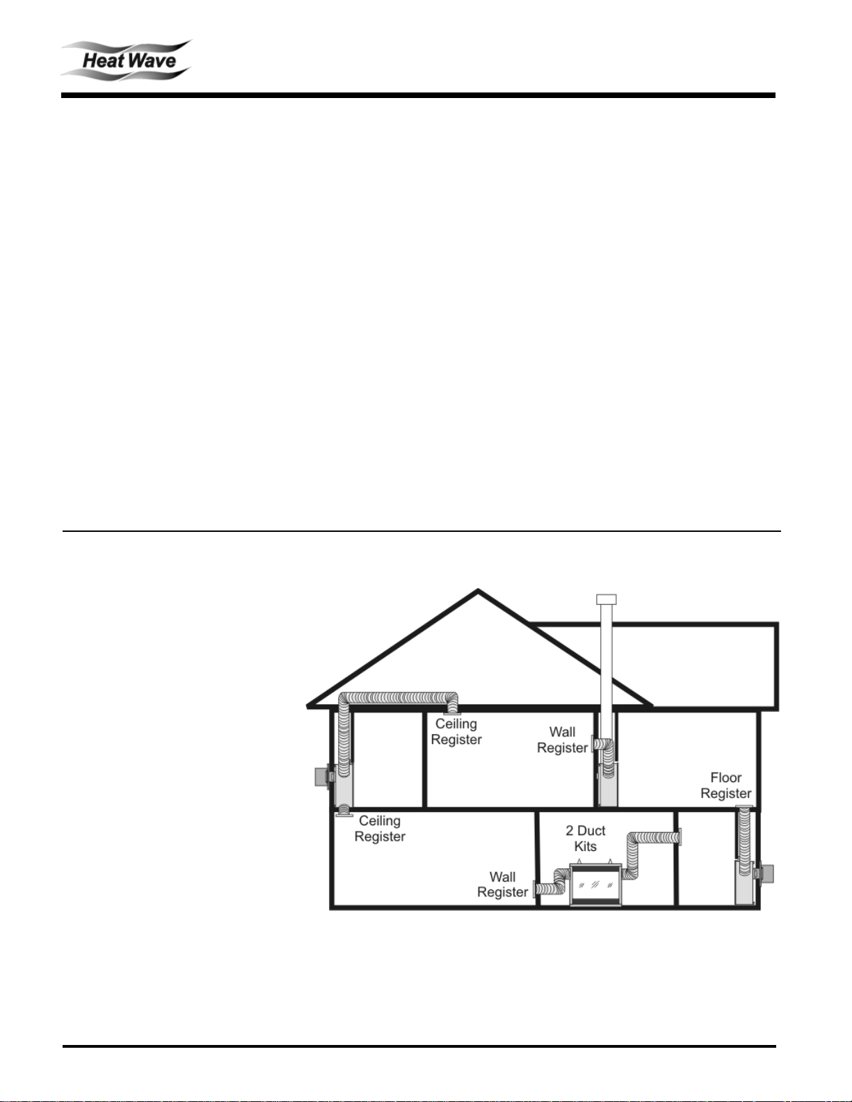
6) Plan the location of the fi replace and the
warm air duct runs, see diagram 1 as a
guide for possible duct runs and locations.
Maximum Duct Run: 20 ft. (6.1m) per
kit.
NOTE: Airfl ow through the duct system is
affected by the duct length and number of
bends. Keep the length and bends to a
minimum to maximize performance.
Included with Kit:
1 946-010 20 ft. (6.1 m) of 6" dia. fl ex pipe
1 946-517 Fan housing assembly
1 910-423 Variable wall rheostat
1 946-006 Air register
1 946-005 Register adaptor frame (thick)
1 946-000 Round Duct collar
1 946-001 Oval Duct collar
1 946-002 Duct adaptor (round to oval)
1 946-045 Insulation (60")
Hardware package
If any parts are missing or damaged, contact
your dealer before starting installation. DO
NOT install a damaged kit.
PARTS
Diagram 1: Guide for possible air duct runs and locations. Keep duct length and number of
2
bends to a miniumum. Maximum duct length is 20 ft. (6.1m) per kit.
Regency Heat Wave Air Duct Kit
Page 3
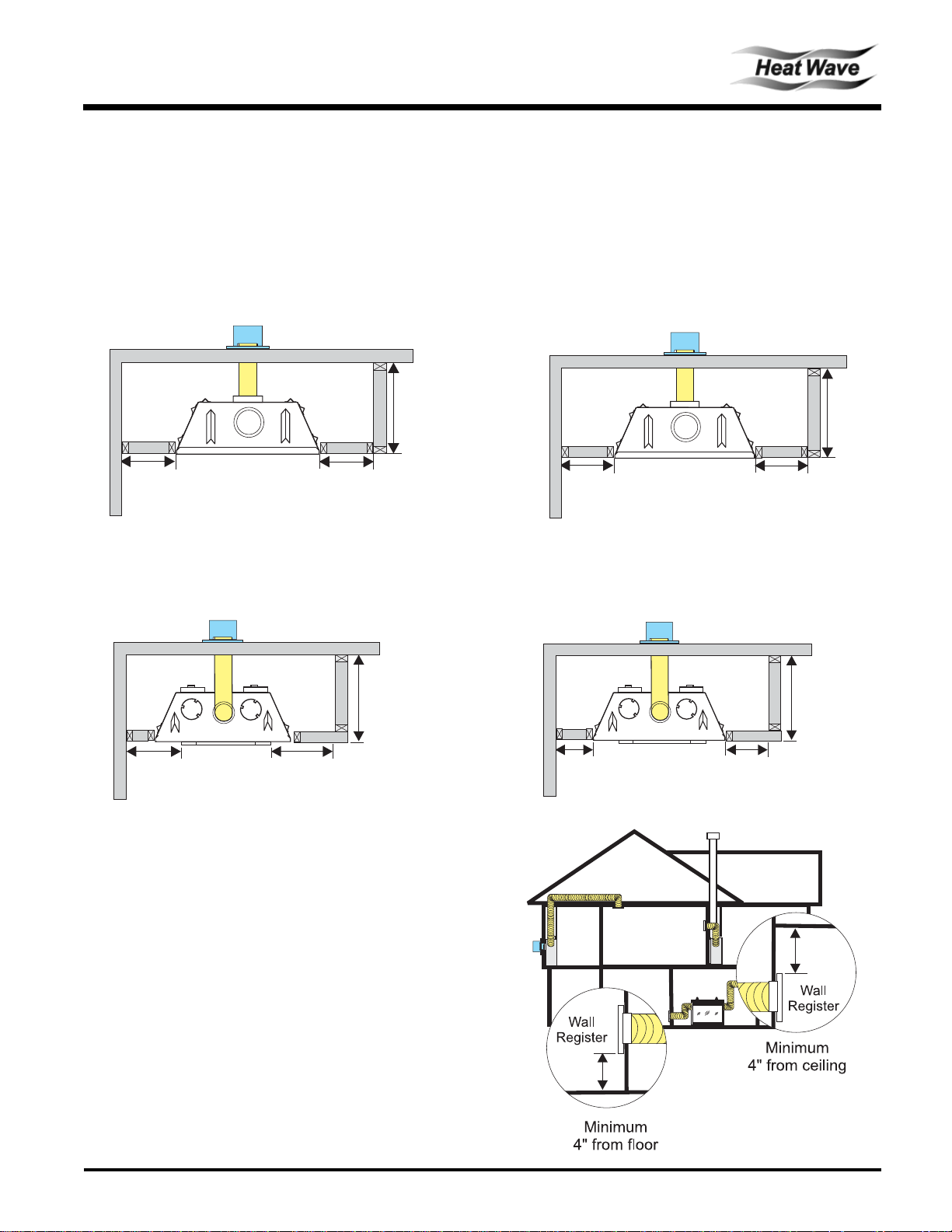
MINIMUM FRAMING CLEARANCES
* Wall studs must be 16" on center for mounting fan housing.
* Fan Housing: Maintain a 1/4" (6mm) clearance from fan housing to combustible material.
* Wall Registers must be 4"(102mm) from fl oor above or ceiling below.
P33 / P36 / P36D / P48
12”
(305mm)
P90 / P95 - Top Exit
6-1/2"
(165mm)
6-1/2"
(165mm)
12”
(305mm)
20” (508mm)
- 20” (508mm)
- 21-1/4” (533mm)
P90
P95
P48
14”
(356mm)
P90 / P95 / HZ54 - Side Exit
14"
(356mm)
(356mm)
(356mm)
14"
14”
26-1/4”
- 22” (559mm)
- 20” (508mm)
- 21-1/4” (533mm)
P90
HZ54
P95
(667mm)
Minimum Duct Clearances
The air duct has a '0' clearance to combustibles but the fi rst 24" of pipe from
the unit requires insulation (included with kit). See diagram 4 on page 3.
Regency Heat Wave Air Duct Kit
3
Page 4
INSTALLATION
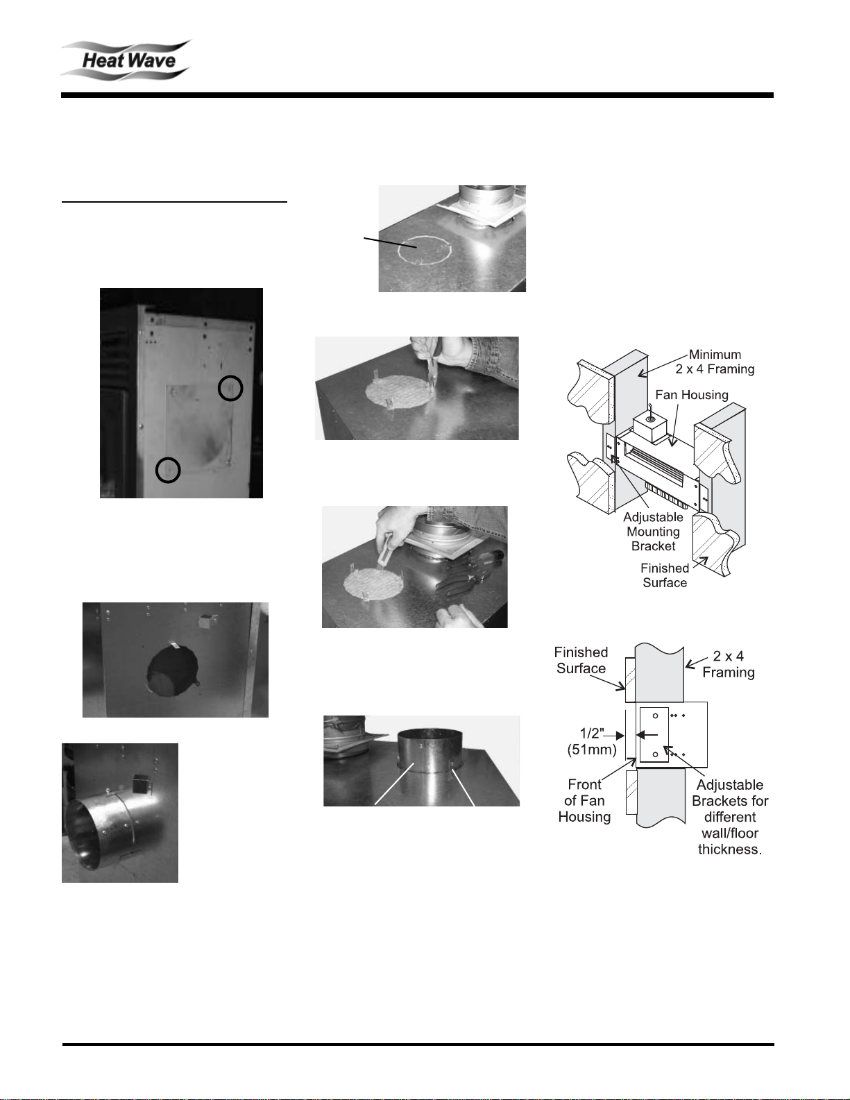
NOTE: Installation of Heat Wave duct kit should
be done prior to drywall installation.
A) P36, P36D, P42, P48, P90, P95 & HZ54
models:
1) Remove the cover plate from the fi replace
side and discard.
Remove the 2 screws holding the cover plate
on the fi replace side.
A) P90 / P95 Model:
1) Remove the knockout plate from the fi re-
place top and discard.
Knockout
plate
2) Bend the tabs outward.
Tab
Tab
Tab
3) Cut out and remove the insulation under the
top opening.
B) All models:
1) Determine the location of the air register/fan
housing assembly. Cut a 5" x 16" (121mm
x 406mm) hole between framing members
(wall studs or fl oor joists). Maintain a 1/4"
(6mm) clearance from fan housing to combustible material. See page 2 for clearances.
2) Mount and secure the fan housing assembly
to framing members, the front of the fan
housing will protrude 1/2" (51mm) out of
the wall so it may be fi nished with drywall,
etc. See diagram 2.
2) Remove the knock-out and bend the tabs
outward.
Tab
Tab
Tab
Center Round
Duct collar over
hole and attach
to the tabs using
3 screws
NOTE: This must be done prior to placing
fi replace into fi nal position.
4) Push Round Duct Collar through to inner
shell top and attach to all 3 tabs on fi replace
top with screws.
Round Duct Collar
pushed down to
inner shell
Tabs
Front View
Diagram 2 Side View: Secure fan housing
to minimum 2 x 4 framing.
4
Regency Heat Wave Air Duct Kit
Page 5
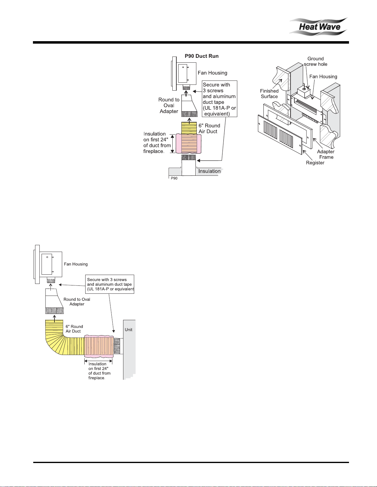
3) Install the air duct run. The air duct run has
a zero clearance to combustibles construction but the fi rst 24" of the pipe from the unit
requires insulation (included with kit). Check
local codes.
Secure the duct to the duct collar on the unit
and to the fan housing with 3 screws (per
end) and aluminum duct tape (UL 181A-P
or equivalent).
The fi rst 24" of duct pipe (from the unit)
must be covered with insulation.
Round Air Duct: Attach the 6" round air
duct (supplied) to the fi replace collar and
run the duct to the fan housing. Attach the
round-to-oval adaptor to the fan housing
and the air duct to the adaptor, diagram 3.
Oval Air Duct: Attach the round-to-oval
adaptor to the fi replace starting collar and
a 6" oval duct (not supplied) to the adaptor.
Complete the duct run and attach the oval
duct to the fan housing.
Round and Oval Duct: A combination of
6" round and 6" oval duct can be used in
the duct run. Oval duct components are
not supplied but can be purchased from an
HVAC supplier.
Diagram 3: P90 model
4) Install the variable speed Wall Rheostat (with
OFF setting) in a convenient location. This
switch controls the fan operation.
5) Wire 120V AC service to the W all Rheostat
and from the Wall Rheostat to the Fan Junction Box. Use wire nuts to secure the 120V
AC wires to the hot and neutral fan wires
and screw the 120V AC ground wire to the
Fan Junction Box. See wiring diagram below.
Diagram 4
8) Complete the fi replace installation as per
fi replace installation manual.
Diagram 3: P36, P36D, P42 & P48 models
6) Screw the fan junction box to the fan housing.
7) Screw the Register Adapter Frame and the
Air Register to the Fan Housing, diagram 4.
Note: For new construction only the Air
Register is required to cover the opening.
Regency Heat Wave Air Duct Kit
5
Page 6
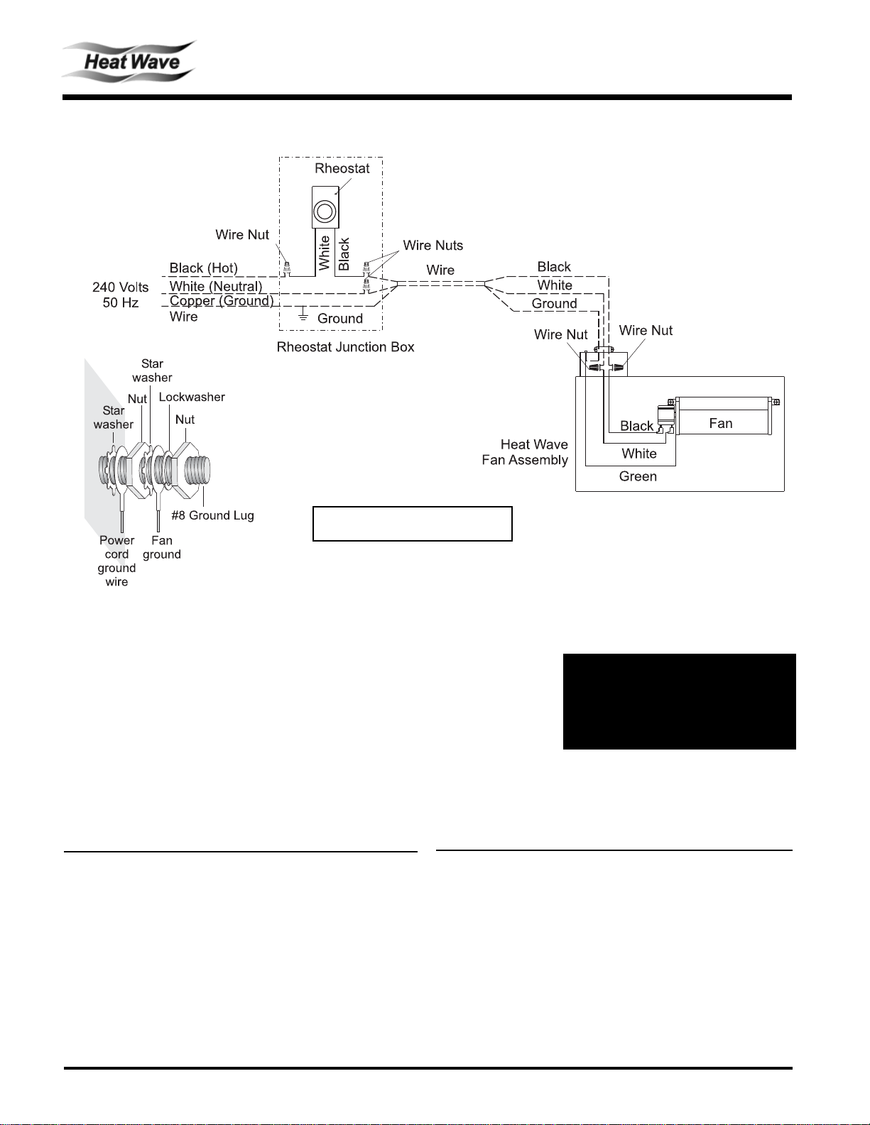
WIRING DIAGRAM
NOTE: The wires (in dotted lines) and
wire nuts are supplied by others.
Ground Lug
Caution: Ensure that the wires do
not touch any hot surfaces and are
Do not cut the ground terminal off
under any circumstances.
away from sharp edges.
IMPORTANT: If the internal blower is installed, it cannot
be operated if the Heat Wave air duct kit fan is operating.
OPERATION
1) Start the fi replace as per instructions and allow it to warm up.
2) Turn the Wall Rheostat "ON" and adjust the variable speed based
upon desired air fl ow at the Air Duct Register.
CAUTION: Label all wires prior
to disconnection when servicing controls. Wiring errors can
cause improper and dangerous
operation.
MAINTENANCE
1) Service and maintain the fi replace as per the fi replace installation
manual.
2) Keep the Air Register(s) clean and free of any blockage.
6
Regency Heat Wave Air Duct Kit
Page 7
NOTES
Regency Heat Wave Air Duct Kit
7
Page 8

Printed in Canada© FPI Fireplace Products International Ltd. 2009
 Loading...