

Page 1
www.hampton-fire.com
H35 Direct Vent Gas Fireplace
Owners &
Installation Manual
MODELS: H35-NG Natural Gas H35-LP Propane
WARNING:
If the information in these instructions are not followed exactly,
a fire or explosion may result causing property damage,
personal injury or loss of life.
FOR YOUR SAFETY
Do not store or use gasoline or other flammable vapors and
liquids in the vicinity of this or any other appliance.
Installation and service must be performed by a qualified
installer, service agency or the gas supplier.
Tested by:
Installer: Please complete the details on the back cover
and leave this manual with the homeowner.
Homeowner: Please keep these instructions for future reference.
918-085b
FPI FIREPLACE PRODUCTS INTERNATIONAL LTD. 6988 Venture St., Delta, BC Canada, V4G 1H4
FOR YOUR SAFETY
What to do if you smell gas:
Do not try to light any appliance
Do not touch any electrical switch:
do not use any phone in your
building.
Immediately call your gas supplier
from a neighbour's phone. Follow
the gas supplier's instructions.
If you cannot reach your gas supplier, call the fire department.
01/09/06
Page 2
HAMPTON
Direct Vent Freestanding Gas Stove
To the New Owner:
Congratulations!
You are the owner of a state-of-the-art Hampton Gas Stove by FPI FIREPLACE PRODUCTS INTERNATIONAL LTD .
The H35 is a hand crafted appliance and has been designed to provide you with all the warmth and charm of a wood
fireplace at the flick of a switch. The model H35 has been approved by Warnock Hersey for both safety and efficiency.
As it also bears our own mark, it promises to provide you with economy, comfort and security for many trouble free
years to follow. Please take a moment now to acquaint yourself with these instructions and the many features of your
Hampton Stove.
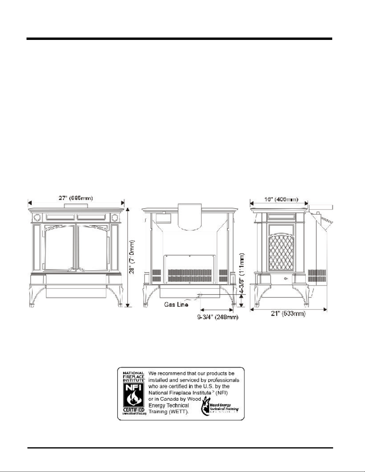
UNIT DIMENSIONS
2 Hampton H35 Direct Vent Freestanding Gas Stove
Page 3

TABLE OF CONTENTS
Page Page
Safety Label
Safety Labels ......................................................... 4
Installation
Specifications .......................................................... 5
Information for Mobile/Manufactured Home
After First Sale .................................................. 5
Before You Start ...................................................... 5
General Safety Information ........................................ 6
Installation Checklist ................................................ 6
Clearances to Combustibles ..................................... 6
Locating Your Gas Stove ......................................... 7
Manufactured Mobile Home Requirements.................. 7
Combustion and Ventilation Air ................................. 7
Optional Fan Installation ........................................... 7
Venting Introduction ................................................. 8
Installation Precautions ............................................ 8
Safety Precautions for the Installer ............................ 8
Vent Restrictor Position............................................ 8
Exterior Vent Terminal Locations ............................... 9
Rigid Pipe Venting Components List ......................... 10
Rigid Pipe Venting Systems
Horizontal or Vertical Terminations ..................... 11
Rotating Elbow for Horizontal Terminations ................ 12
Venting Arrangements - Horizontal Terminations ........ 12
Venting Arrangements - Vertical Terminations ........... 12
Horizontal Vienting With Two Elbows ........................ 14
Vertical Venting With Two Elbows ............................ 15
Vertical Termination with Co-linear Flex system ......... 16
Horizontal Termination Kit ........................................ 17
Horizontal Termination Kit Installation ................. 17
Dura-Vent Termination Kits ...................................... 19
Planning Your Dura-Vent Installation ......................... 19
Minimum Dura-Vent Components - Horizontal
Installation........................................................ 19
Minimum Dura-Vent Components - Vertical
Termination ...................................................... 19
Dura-Vent Venting Components Parts List ................ 20
Dura-Vent Horizontal Installation............................... 20
Dura-Vent Vertical Termination Installation ................ 20
Offset Chart ............................................................ 22
Converting a Class-A Metal Chimney or Masonry
Chimney to a Direct Vent System ............................ 23
Cathedral Ceiling Installations .................................. 24
Support Extension - Round or Square ....................... 24
High Elevation......................................................... 24
Gas Connection ...................................................... 24
System Data Chart ................................................. 24
Aeration Adjustment ................................................ 24
Gas Pipe Pressure Testing ...................................... 25
Valve Description .................................................... 25
Conversion to Propane............................................. 25
Conversion to Lower BTU ......................................... 27
Gas Fireplace - Optional Brick Panel ........................ 28
Log Installation ....................................................... 28
Optional Door Installation ......................................... 30
Optional Door Grill................................................... 30
Optional Tile Inset ................................................... 30
Door Hinge Removal ................................................ 31
Wiring Diagram ....................................................... 32
Optional Wall Thermostat ........................................ 32
Optional Remote Control Installation ......................... 32
Final Check ............................................................ 33
Operating Instructions
Operating Instructions ............................................. 33
Lighting Procedure .................................................. 33
Shutdown Procedure ............................................... 33
First Fire ................................................................ 33
Adjusting Flame Height ........................................... 33
Copy of Lighting Plate Instructions ............................ 34
Convection Fan Operation ........................................ 34
Normal Operating Sounds of
Gas Appliances ................................................ 35
Maintenance
Maintenance Instructions ......................................... 35
General Vent Maintenance .......................................36
Log Replacement .................................................... 36
Glass Replacement ................................................. 36
Fan Maintenance .................................................... 36
Removing and Installing Valve .................................. 37
Parts List
Replacement Parts List ........................................... 38
Warranty
Hampton H35 Direct Vent Freestanding Gas Stove
Warranty ................................................................ 43
3
Page 4
SAFETY LABEL
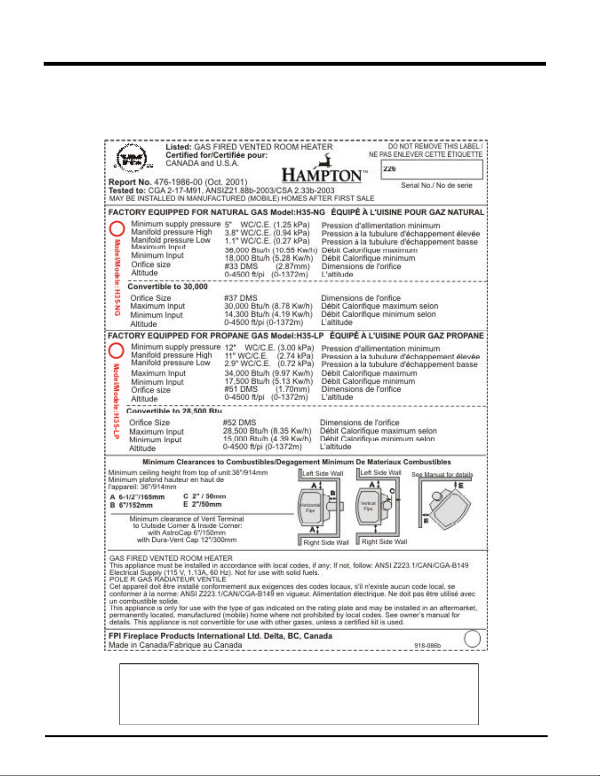
This is a copy of the label that accompanies
each Direct Vent Freestanding Gas Stove. We
have printed a copy of the contents here for
your review.
NOTE: Hampton units are constantly being
improved. Check the label on the unit and if
there is a difference, the label on the unit is
the correct one.
Copy of Safety Label for H35-NG & H35-LP
For the State of Massachusetts, installation and repair must be done by a plumber or gasfitter licensed
in the Commonwealth of Massachusetts.
For the State of Massachusetts, flexible connectors shall not exceed 36 inches in length.
For the State of Massachusetts, the appliances individual manual shut-off must be a t-handle type valve.
4 Hampton H35 Direct Vent Freestanding Gas Stove
Page 5
INSTALLATION
IMPORTANT: SAVE
THESE INSTRUCTIONS
The Direct Vent Freestanding Gas Stove must
be installed in accordance with these instructions. Carefully read all the instructions in this
manual first. Consult the building authority having jurisdiction to determine the need for a
permit prior to starting the installation.
Note: Failure to follow the instructions
could cause a malfunction of the
heater which could result in death,
serious bodily injury, and/or property damage. Failure to follow
these instructions may also void
your fire insurance and/or warranty.
Note: These instructions take prece-
dence over Simpson Dura-Vent
instructions.
SPECIFICATIONS
Fuels: H35-NG is approved for use with
natural gas.
H35-LP is approved for use with
liquefied petroleum gases (propane).
Electrical: 120V A.C. system.
Circulation Fan: Variable speed, 125/75.
Log Sets: Ceramic fibre, 7 per set.
Vent System: Coaxial (6-5/8" outer / 4" inner
liner) rigid flue and termination cap.
The efficiency rating of the appliance is a
product thermal efficiency rating determined
under continuous operating conditions and
was determined independent of any installed
system.
INFORMATION FOR
MOBILE/
MANUFACTURED
HOMES AFTER
FIRST SALE
This Hampton product has been tested and
listed by ITS Testing Services as a Direct Vent
Wall Furnace to the following standards:
CGA-2.17-M91, and ANSI Z21.88b-2003/CSA
2.33b-2003.
This Direct Vent System Appliance must be
installed in accordance with the manufacturer's installation instructions and the Manufac-
tured Home Construction and Safety Standard,
Title 24 CFR, Part 3280, or the current Standard
of Fire Safety Criteria for Manufactured Home
Installations, Sites, and Communities ANSI/
NFPA 501A, and with CAN/CSA Z240-MH Mobile Home Standard in Canada.
This appliance installation must comply with the
manufacturer's installation instructions and local codes, if any. In the absence of local codes
follow the current National Fuel Gas Code, ANSI
Z223.1 and the current National Electrical Code
ANSI/NFPA 70 in the U.S.A., and the current
CAN/CGA B149 Gas Installation Code and the
current Canadian Electrical Code CSA C22.1 in
Canada.
This Hampton Mobile/Manufactured
Home Listed appliance comes factory
equipped with a means to secure the
unit.
This Hampton Mobile/Manufactured
Home listed appliance comes
equipped with a dedicated #8 ground
lug to which an 18 gauge copper wire
from the steel chassis ground must be
attached.
This appliance may only be installed in
an aftermarket permanently located,
manufactured (USA only )or mobile
home, where not prohibited by local
codes.
This appliance is only for use with the
type of gas indicated on the rating
plate. This appliance is not convertible for use with other gases, unless a
certified kit is used.
BEFORE YOU START
Safe installation and operation of this appliance
requires common sense, however, we are
required by the Canadian Safety Standards
and ANSI Standards to make you aware of the
following:
INSTALLATION AND REPAIRS
SHOULD BE DONE BY A QUALIFIED SERVICE PERSON. THIS APPLIANCE SHOULD BE INSTALLED,
REPAIRED, INSPECTED BEFORE
USE AND AT LEAST ANNUALLY
BY A QUALIFIED SERVICE PERSON. MORE FREQUENT CLEANING MAY BE REQUIRED DUE TO
EXCESSIVE LINT FROM CARPETING, ETC. IT IS IMPERATIVE THAT
THE CONTROL COMPARTMENT,
BURNERS AND CIRCULATING AIR
PASSAGEWAYS OF THE APPLIANCE BE KEPT CLEAN.
DUE TO HIGH TEMPERATURES,
THE APPLIANCE SHOULD BE LOCATED OUT OF TRAFFIC AND
AWAY FROM FURNITURE AND
DRAPERIES.
WARNING: FAILURE TO INSTALL
THIS APPLIANCE CORRECTLY
WILL VOID YOUR WARRANTY AND
MAY CAUSE A SERIOUS HOUSE
FIRE.
CHILDREN AND ADULTS SHOULD
BE ALERTED TO THE HAZARDS
OF HIGH SURFACE TEMPERATURES, ESPECIALLY THE FIREPLACE GLASS, AND SHOULD
STAY AWAY TO AVOID BURNS
OR CLOTHING IGNITION.
YOUNG CHILDREN SHOULD BE
CAREFULLY SUPERVISED WHEN
THEY ARE IN THE SAME ROOM AS
THE APPLIANCE.
CLOTHING OR OTHER FLAMMABLE MATERIAL SHOULD NOT BE
PLACED ON OR NEAR THE APPLIANCE.
1) Provide adequate clearances for servic-
ing, proper operation and around the air
openings into the combustion chamber.
2) The appliance must be installed on a flat,
solid, continuous surface (e.g. wood, metal, concrete). This may be the floor, or it can
be raised up on a platform to enhance its
visual impact. The appliance may be installed on carpeting, tile, wood flooring or
other combustible material, because the
appliance's base extends the full width and
depth of the appliance. The Direct Vent
Freestanding Gas Stove can be installed in
a wide variety of ways and will fit nearly
any room layout. It may be installed in a
recessed position, framed out into the room,
or across a corner.
3) The Direct Vent Freestanding Gas Stove is
approved for alcove installations, which
meet the clearances listed on page 6. This
unit is approved for manufactured home
installations, see page 7 and pages 12 to 16
for the required vent arrangements. If installed into a manufactured home the unit
must be bolted down to the floor.
Hampton H35 Direct Vent Freestanding Gas Stove
5
Page 6
INSTALLATION
4) This appliance is Listed for bedroom instal-
lations when used with a Listed Millivolt
Thermostat. Some areas may have further
requirements, check local codes before
installation.
5) This appliance is Listed for Alcove installations, maintain minimum Alcove clearances
as follows, minimum width of 40" (1016mm),
a maximum depth of 36" (914mm), and
minimum ceiling height of 64" (1626mm)
from floor to ceiling.
6) We recommend that you plan your installation on paper using exact measurements
for clearances and floor protection before
actually installing this appliance. Have a
qualified building inspector review your
plans before installation.
GENERAL SAFETY
INFORMATION
1) The appliance installation must conform
with local Canadian Electrical Code.
2) The appliance when installed, must be electrically grounded in accordance with local
codes, or in the absence of local codes with
the current National Electrical Code, ANSI/
NFPA 70 or CSA C22.1 Canadian Electrical
Code.
3) The appliance should be inspected for
shipping damage before use and serviced
annually by a professional service person. More frequent cleaning may be re-
quired due to excessive lint from carpeting,
bedding material, etc. It is imperative that
control compartments, and circulating air
passageways of the appliance be kept
clean and free from excessive lint from
carpeting.
4) See general construction and assembly
instructions. The appliance and vent should
be enclosed when installed in or passing
through a living area, where children may
come in contact with it.
9) To prevent injury, do not allow anyone who
is unfamiliar with the operation to use the
fireplace.
Emissions from burning wood or gas could
contain chemicals known to the State of
California to cause cancer, birth defects or
other reproductive harm.
INSTALLATION
CHECKLIST
1) Check Clearances to Combustibles (page
6), location of unit (page 7) and venting
requirements (pages 8-15).
2) Install Optional Fan, see page 7.
3) Set vent restrictors, page 8.
4) Install venting: Check all venting require-
ments, pages 8-15. Vertical Termination
with Co-linear Flex System, page 16. Horizontal Termination Kits , page 17. DuraVent Termination Kits, page 19.
5) Make gas connections, page 24. Test the
pilot. Must be as per diagram, page 35.
If converting to Propane, make changes
prior see pages 25.
6) Test Gas Pressure, page 25.
7) Install logs and embers where indicated on
page 28.
8) Install optional Remote Control, or Wall Thermostat, page 32.
9) Final check, page 33.
Before leaving this unit with the customer, the
installer must ensure that the appliance is firing
correctly and operation fully explained to
customer.
This includes:
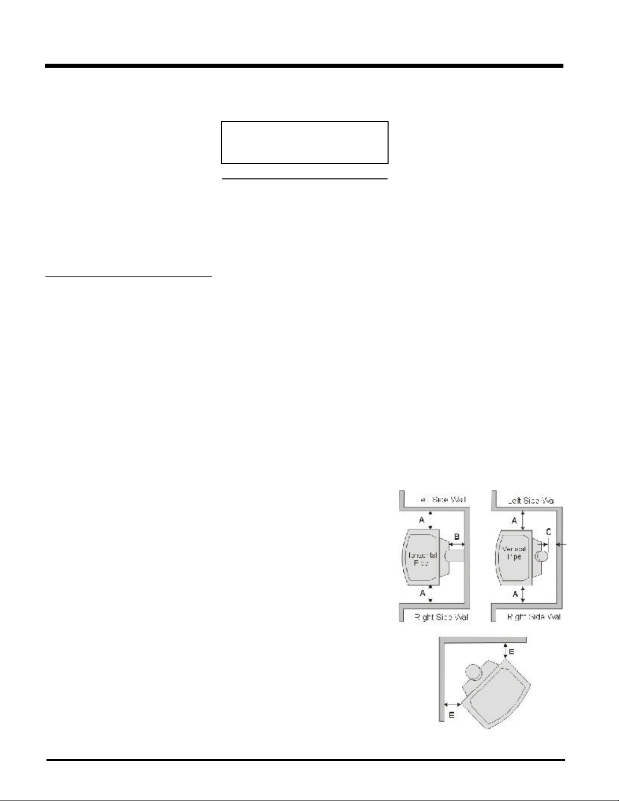
CLEARANCES TO
COMBUSTIBLES
The clearances listed are MINIMUM distances.
Measure the clearance to both the appliance
and the chimney connector. The farthest
distance is correct if the two clearances
do not coincide.
For example, if the appliance is set as indicated
in one of the figures but the connector is too
close, move the stove until the correct clearance to the connector is obtained.
This appliance may be installed only with the
clearances as shown in the situations pictured.
Do not combine clearances from one
type of installation with another in order
to achieve closer clearances.
This unit can be installed on a solid combustible
surface like a wood floor. This unit can also be
installed directly on carpeting or vinyl.
Use the minimum clearances shown in the
diagrams below:
H35-NG & H35-LP Clearances
A Side Wall to Unit 6-1/2" / 165 mm
B Back Wall to Unit 6" / 152 mm
C Vertical Vent Pipe to Back Wall
2" / 50 mm
E Unit Corner to Wall 2" /50 mm
Unit Top to Alcove Ceiling 36" / 914 mm
Minimum ceiling height is 36" /914 mm from top
of unit.
5) This appliance must be connected to the
specified vent and termination cap to the
outside of the building envelope. Never vent to another room or inside a building.
Make sure that the vent is fitted as per the
instructions starting on page 9.
6) Inspect the venting system annually for
blockage and any signs of deterioration.
7) Venting terminals shall not be recessed into
a wall or siding.
8) Any safety glass removed for servicing
must be replaced prior to operating the
appliance.
6 Hampton H35 Direct Vent Freestanding Gas Stove
1) Clocking the appliance to ensure the correct firing rate (rate noted on label) after
burning appliance for 15 minutes.
2) If required, adjusting the primary air to
ensure that the flame does not carbon. First
allow the unit to burn for 15-20 min. to
stabilize.
CAUTION: Any alteration to the product
that causes sooting or carboning that
results in damage is not the responsibility of the manufacturer.
Page 7
INSTALLATION
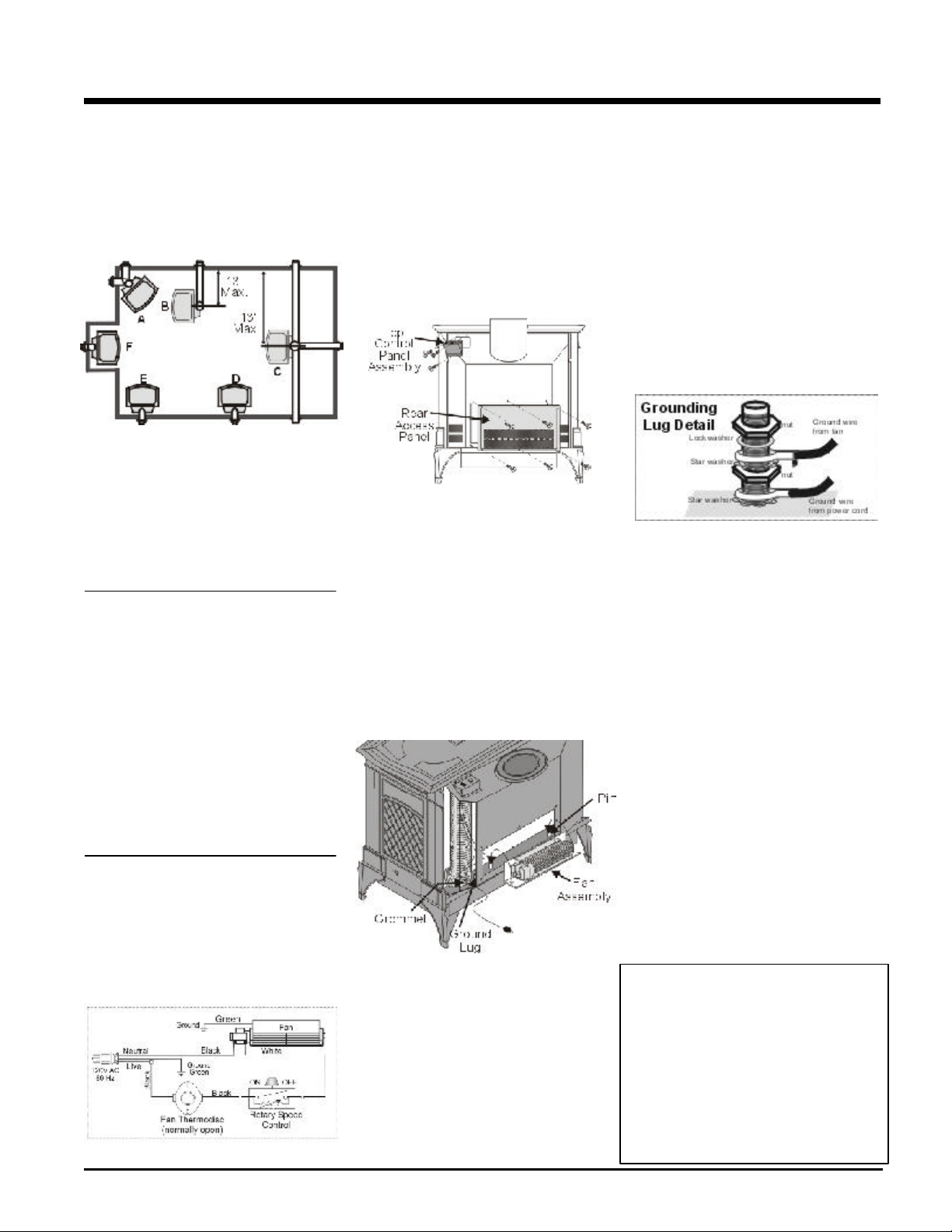
LOCATING YOUR
GAS STOVE
When selecting a location for your stove, ensure that the clearances listed above are met as
well as ensuring that there is adequate accessibility for servicing and proper operation.
A) Cross Corner
B) Room Divider
C) Island
D) Flat on Wall
E) Flat on Wall Corner
F) Flush with Wall/Alcove
For Vent Termination requirements,
see page 9.
MANUFACTURED
MOBILE HOME
ADDITIONAL
REQUIREMENTS
1) Ensure that structural members are not cut
or weakened during installation.
OPTIONAL FAN INSTALLATION
Fan Kit Contains:
Qty. Description
1 Fan Speed Controller with nut, and knob.
1 Fan Assembly c/w green wire attached
1 power cord
1 Plastic locking grommet
1) Remove the Top Control Panel Assembly by
removing the three screws. Diagram 1.
Diagram 1
2) Remove the nylon hole plug from the control
panel.
3) Install the fan speed controller onto the
control panel and secure with nut. Connect
remaining wire harness wires to speed
control. NOTE: Speed control wires must
be in the down position when control panel
is in place.
4) Push black knob onto speed control.
5) Remove the rear access panel on the back
of the stove by removing the 6 screws.
Install the fan onto pins as per diagram 2.
7) Install locking grommet to power cord and
push through hole in the rear panel and give
a 1/4 turn to secure.
NOTE: When running wires, keep them
clear of valve assembly and tubing to avoid tangling of wires and
valve.
NOTE: Be careful not to cut wires when
passing through holes in the firebox.
8) Run green ground wire from fan and con-
nect to grounding lug.
9) Connect green power cord ground wire to
grounding lug.
10)Run the neutral black wire from power cord
and connect to fan motor.
11)Run the live black wire from power cord and
connect to speed control wire.
12)Connect the white wire of the wire harness
to the fan terminal.
NOTE: Pull excess wire next to fan to
avoid excessive heat from the firebox.
2) Ensure proper grounding using the #8
ground lug provided.
3) Appliance must be anchored to the floor
with the supplied anchoring methods.
COMBUSTION AND
VENTILATION AIR
The combustion air from this appliance is drawn
from outside the building through the outer flue.
Extra provision for combustion air inside
the room is not required.
Hampton H35 Direct Vent Freestanding Gas Stove
Diagram 2
NOTE: Do NOT damage, cut or remove
the 3" aluminum air intake pipes.
Hint for pushing fan down onto pins - rub a
bit of dish soap on the pins so the grommets will slide down more easily. Check to
make sure the fan is seated properly on the
pins - try to move the fan back and forth.
6) Push power cord through hole in the rear
panel 14" - 16" and tie a loose knot in the cord
on the inside to prevent the power cord
from being pulled out. Diagram 2.
13)Ensure all wires are pulled away from
firebox to avoid excessive heat and secure
with stick-on wire clip.
14)Re-attach control panel with 3 screws,
reversing step 1. Re-attach rear access
panel with 6 screws, reversing step 5.
NOTE: When power cord is plugged in,
speed control is in the ON position and
stove is burning, allow 10 - 15 minutes for
the thermodisc (temperature switch) to
activate and turn on the Fan automatically.
WARNING:
Electrical Grounding Instructions
This appliance is equipped with a
three pronged (grounding) plug for
your protection against shock hazard and should be plugged directly
into a properly grounded threeprong receptacle. Do not cut or remove the grounding prong from
this plug.
7
Page 8
INSTALLATION
VENTING
INTRODUCTION
The Horizontal Termination Kit and the Simpson
Dura-Vent Direct Vent System Model DV-GS
venting systems, in combination with the Direct
Vent Freestanding Gas Stoves, H35-NG, and
H35-LP , have been tested and listed as direct
vent heater systems by Warnock Hersey.
These units use the "balanced flue" technology
Co-Axial system. The inner liner vents products
of combustion to the outside while the outer
pipe draws outside combustion air into the
combustion chamber thereby eliminating the
need to use heated room air for combustion and
losing warm room air up the chimney.
Note: These flue pipes must not be
connected to any other appliance.
The gas appliance and vent system must be
vented directly to the outside of the building, and
never be attached to a chimney serving a
separate solid fuel or gas burning appliance.
Each direct vent gas appliance must use it's
own separate vent system. Common vent systems are prohibited.
IMPORTANT
INSTALLATION
PRECAUTIONS
These venting systems are engineered products that have been designed and tested for
use with the H35-NG, and H35-LP . The warranty will be voided and serious fire, health or other
safety hazards may result from any of the
following actions:
1) Installation of any damaged Direct Vent
component
2) Unauthorized modification of the Direct Vent
System
3) Installation of any component part not manufactured or approved by Simpson DuraVent or FPI Fireplace Products International
Ltd.
4) Installation other than as instructed by Simpson Dura-Vent and FPI Fireplace Products
International Ltd.
Warning: Always maintain required
clearances (air spaces) to nearby
combustibles to prevent a fire hazard. Do not fill air spaces with insulation.
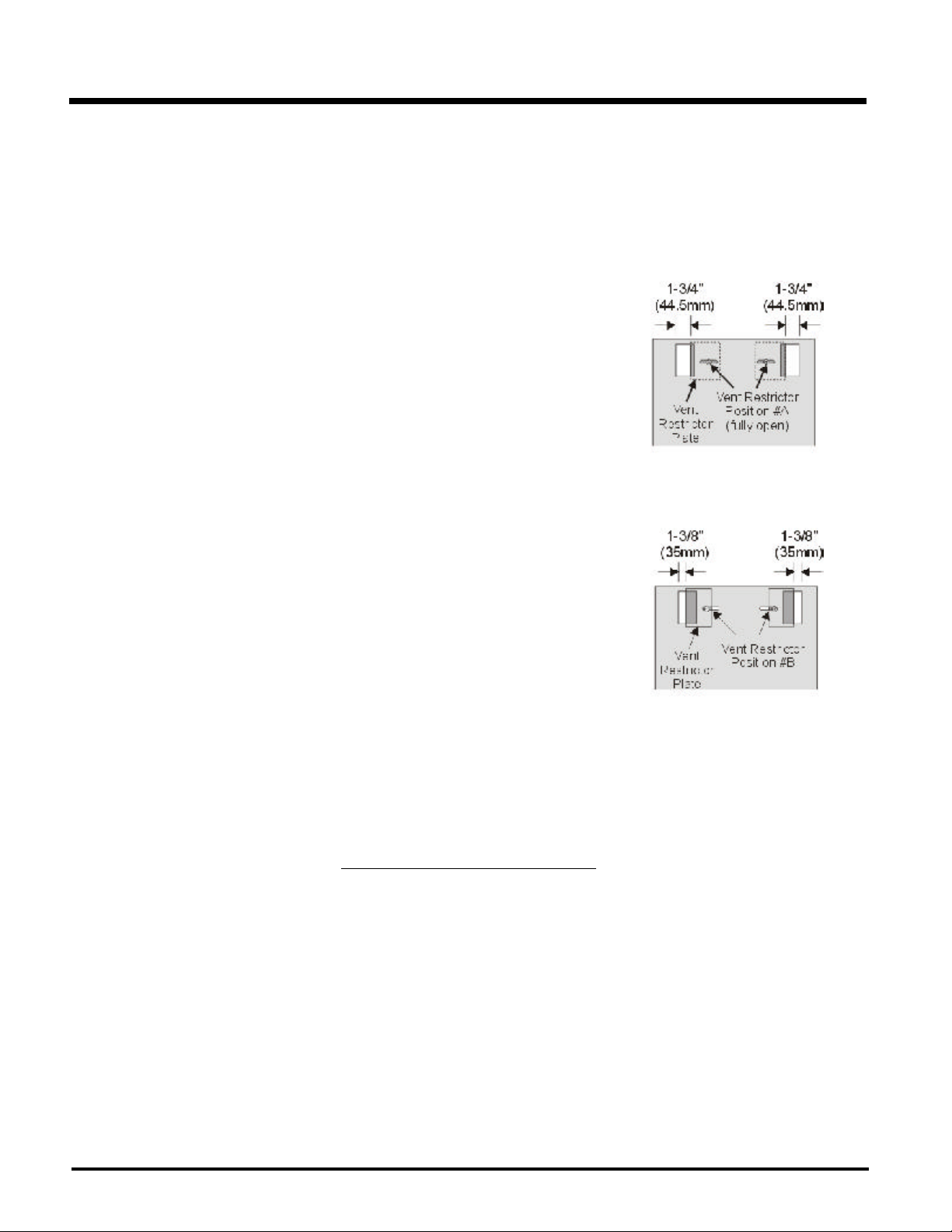
VENT RESTRICTOR
POSITION
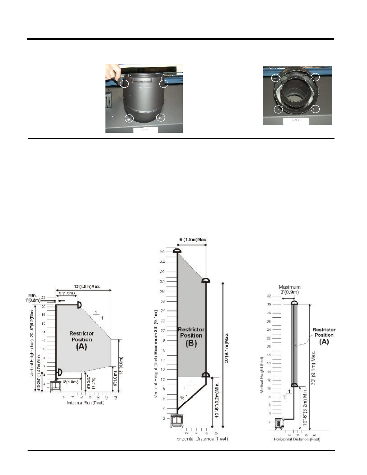
To set the Vent restriction as indicated in the
Venting Arrangement diagrams on pages 1620, simply loosen the screws and push the vent
restrictor plate to the correct position. Tighten
the screws.
Horizontal Termination:
Vent Restrictor setting at 36,000 Btu/h
Read all instructions carefully before starting
the installation. Failure to follow these instructions may create a fire or other safety hazard,
and will void the warranty. Be sure to check the
venting and clearance to combustible requirements. Consult your local building codes
before beginning installation.
The location of the termination cap must conform to the requirements in the Exterior Vent
Terminal Locations on page 9.
Be sure to check the vent termination clearance
requirements from decks, windows, soffits,
gas regulators, air supply inlets and public
walkways as specified in the Exterior Vent
Terminal Locations on page 9 and in your local
building codes.
The gas appliance and vent system must
be vented directly to the outside of the
building, and never be attached to a chimney serving a separate solid fuel or gasburning appliance. Each direct vent gas
appliance must use it's own separate vent
system. Common vent systems are prohibited.
SAFETY
PRECAUTIONS FOR
THE INSTALLER
1) Wear gloves and safety glasses for pro-
tection.
2) Exercise extreme caution when using ladders or on roof tops.
3) Be aware of electrical wiring locations in
walls and ceilings.
Vent Restrictor setting at 36,000 Btu/h
Vertical Termination:
8 Hampton H35 Direct Vent Freestanding Gas Stove
Page 9
INSTALLATION
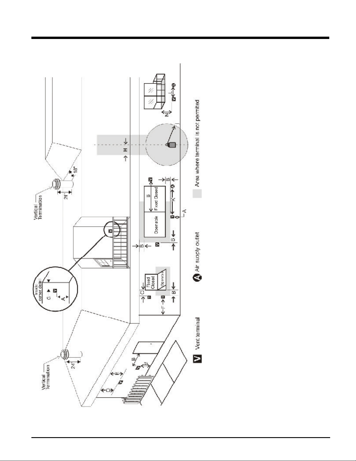
EXTERIOR VENT TERMINAL LOCATIONS
any other appliance *(12"/30cm)
*(min. 84"/2.1m)
J= Clearance to service regulator vent outlet *(min. 36"/90cm)
K= Clearance to non-mechanical air supply inlet to building or the combustion air inlet to
L= Clearance to a mechanical air supply inlet *(min. 72"/1.8m)
M= **Clearance above paved sidewalk or a paved driveway located on public property
N= Clearance under veranda, porch, deck, or balcony *(min. 12"/30cm)***
Note: * As specified in CGA B149 Installation Code. Note: Local codes or regulations may
require different clearances.
**A vent shall not terminate directly above a sidewalk or paved driveway which is located
between two single family dwellings and serves both dwellings.
***Only permitted if veranda, porch, deck, or balcony is fully open on a minimum of two
sides beneath the floor.
Hampton H35 Direct Vent Freestanding Gas Stove
distance of (24"/60cm) from the centerline of the terminal (min. 22"/55cm) check with
local code.
Vent Termination Cap (min.12"/30cm), with Riser Vent (min. 6"/15cm)
Vent Termination Cap (min.12"/30cm), with Riser Vent (min. 6"/15cm)
the centerline of the regulator.
A= Clearance above grade, veranda, porch, deck, or balcony *(min. 12"/30cm)
B= Clearance to window or door that may be opened *(12"/30cm)
C= Clearance to permanently closed window *(min. 12"/30cm)
D= Vertical clearance to ventilated soffit located above the terminal within a horizontal
E= Clearance to unventilated soffit (min. 12"/30cm)
F= Clearance to outside corner: with AstroCap Termination Cap (min. 6"/15cm), with Dura-
G= Clearance to inside corner: with AstroCap Termination Cap (min. 6"/15cm), with Dura-
H= Not to be installed above a meter/regulator assembly within (3'/90cm) horizontally from
9
Page 10

INSTALLATION
RIGID PIPE VENTING COMPONENTS LIST
Description Simpson Dura-Vent Selkirk Amerivent
6" Pipe Length, Galvanized 908 4DT-6 N/A
6" Pipe Length, Black 908B 4DT-6B N/A
7" Pipe Length, Galvanized N/A N/A 4D7
7" Pipe Length, Black N/A N/A 4D7B
9" Pipe Length, Galvanized 907 4DT-9 N/A
9" Pipe Length, Black 907B 4DT-9B N/A
12" Pipe Length, Galvanized 906 4DT-12 4D12
12" Pipe Length, Black 906B 4DT-12B 4D12B
18" Pipe Length, Galvanized N/A 4DT-18 N/A
18" Pipe Length, Black N/A 4DT-18B N/A
24" Pipe Length, Galvanized 904 4DT-24 4D2
24" Pipe Length, Black 904B 4DT-24B 4D2B
36" Pipe Length, Galvanized 903 4DT-36 4D3
36" Pipe Length, Black 903B 4DT-36B 4D3B
48" Pipe Length, Galvanized 902 4DT-48 4D4
48" Pipe Length, Black 902B 4DT-48B 4D4B
Adjustable Length, 11"-14", Galv. 911 4DT-AJ N/A
Adjustable Length, 11"-14", Black 911B 4DT-AJB N/A
Adjustable Length, 17"-24", Black 917B N/A N/A
Adjustable Length, 7" Galvinized N/A N/A 4D7A
Adjustable Length, 7" Black N/A N/A 4D7AB
Adjustable Length, 12" Galvinized N/A N/A 4D12A
Adjustable Length, 12" Black N/A N/A 4D12AB
45O Elbow, Galvinized 945 4DT-EL45 4D45L
45O Elbow, Black 945B 4DT-EL45B 4D45LB
45O Elbow, Swivel, Galvinized 945G N/A N/A
45O Elbow, Swivel, Black 945BG N/A N/A
90O Elbow, Galvinized 990 4DT-EL90S 4D90LS
90O Elbow, Black 990B 4DT-EL90SB 4D90LBS
90O Elbow, Swivel, Galvinized 990G N/A N/A
90O Elbow, Swivel, Black 990BG N/A N/A
Ceiling Support 949 - n/a from FPI 4DT-CS 4DFSP
Cathedral Support Box 941 4DT-CSS 4DRSB
Wall Support/Band 988 4DT-WS/B 4DWS
Offset Support 989 - n/a from FPI 4DT-OS N/A
Wall Thimble, Black 942 4DT-WT 4DWT
Wall Thimble Support Box/Ceiling Support 940 N/A N/A
Firestop Spacer 963 4DT-FS 4DFSP
Trim Plate, Black N/A 4DT-TP 4DFPB
Brass Trim for Wall Thimble/Ceiling Support 3951 N/A N/A
Attic Insulation Shield 12" N/A N/A 4DAIS12
Attic Insulation Shield - Cold Climates 36" N/A N/A 4DAIS36
All Simpson Dura-Vent components are available directly from FPI.
Direct VentGS
R
Direct-Temp
TM
R
Direct Vent
Basic Horizontal Termination Kit (A) 970 4DT-HKA 4DHTK2
Horizontal Termination Kit (B) 971 4DT-HKB 4DHTK1
Vertical Termination Kit 978 4DT-VKC 4DVTK
High Wind Vertical Cap 991 N/A N/A
High Wind Horizontal Cap 985 N/A N/A
Horizontal Square Termination Cap 984 4DT-HHC 4DHC
Verical Termination Cap 980 4DT-HVC 4DVC
Storm Collar 953 4DT-SC 4DSC
Adjustable Flashing, 0/12-6/12 943 4DT-AF6 4DF
Adjustable Flashing, 6/12-12/12 943S 4DT-AF12 4DF12
Vinyl Siding Standoff 950 4DT-VS N/A
Vinyl Siding Shield Plate N/A 4DT-VSP N/A
Snorkel Termination 14" 982 4DT-ST14 4D12S
Snorkel Termination 36" 981 4DT-ST36 4D36S
946-506/P Vent Guard (Optional)
640-530/P Riser Vent Terminal
946-205 Vinyl Siding Shield for Riser Vent Terminal
946-208/P Vent Guard (Optional) - Riser Vent Terminal
946-523/P AstroCap Horizontal Cap
946-206 Vinyl Siding Standoff - AstroCap
10 Hampton H35 Direct Vent Freestanding Gas Stove
Page 11
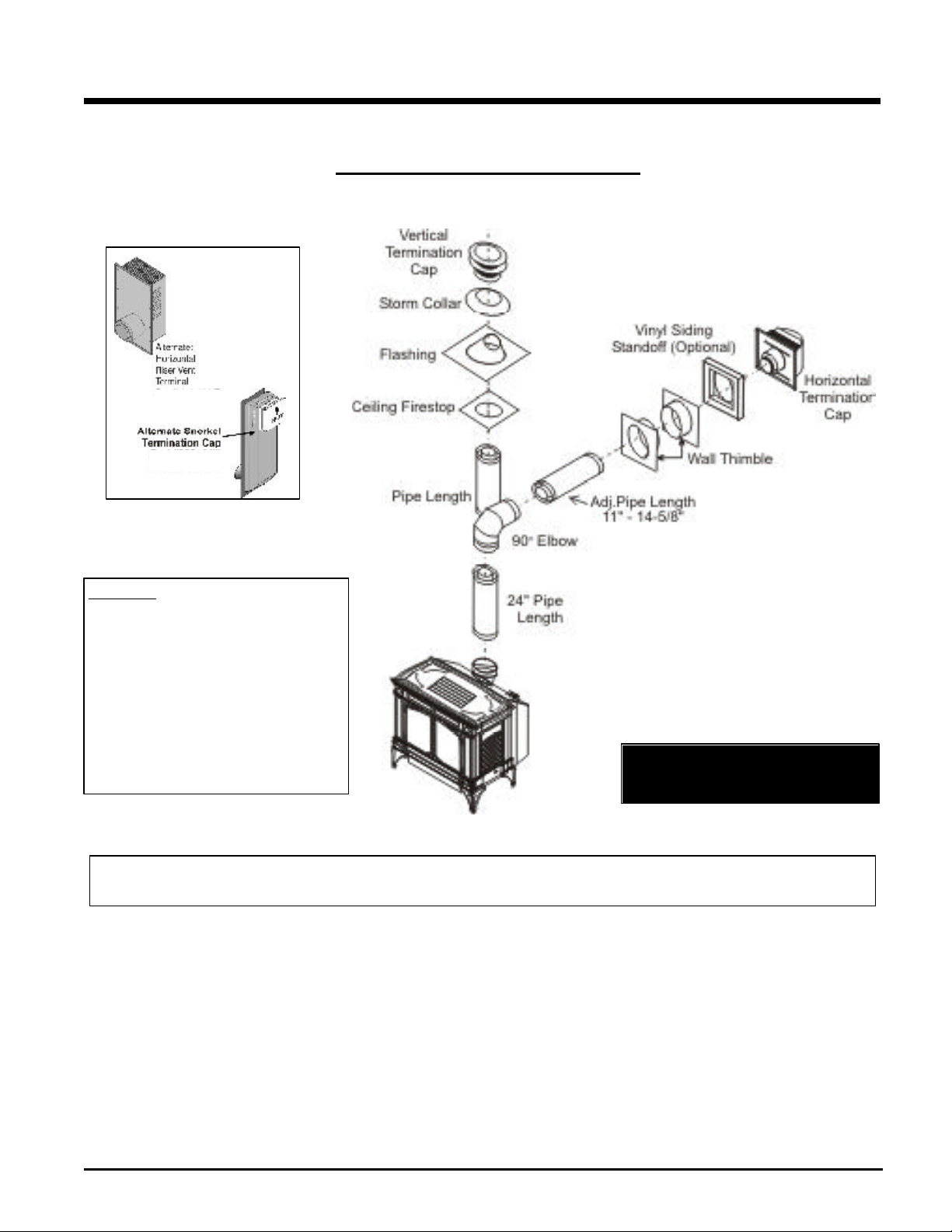
Alternate
Horizontal
Termination
Caps
INSTALLATION
RIGID PIPE VENTING SYSTEMS
Horizontal or Vertical Terminations
WARNING:
Do not combine venting components from
different venting systems.
However use of the the AstroCapTM and FPI
Riser is acceptable with all systems.
This product has been evaluated by Intertek for
using a Dura-Vent Flue Adaptor in conjunction
with Selkirk Direct-Temp and Ameri Vent Direct
venting systems. Use of these systems with
the Direct Vent GS starting collar is deemed
acceptable and does not affect the Intertek WHI
listing of components.
The FPI AstroCap
GS, American Metal Products, Ameri Vent Direct vent and Selkirk Direct-Temp. FPITM, and FPI AstroCapTM are the proprietary trademarks of FPI
Fireplace Products International Ltd. Dura-Vent® and Direct Vent GS are registered and/or proprietary trademarks of Simpson Dura-Vent Co. Inc.
TM
and FPI Riser Vent terminal is certified for installations using FPI venting systems as well as Simpson Dura-Vent®, Direct Vent
When using piping other than Simpson
Dura-Vent, 3 screws must be used to
secure rigid pipe to adaptor.
Hampton H35 Direct Vent Freestanding Gas Stove
11
Page 12
INSTALLATION
ROTATING 45O ELBOW FOR STRAIGHT HORIZONTAL TERMINA TIONS
1) Remove all 4 screws that se-
cure the elbow to the unit using a
1/4" magnetic nut driver.
Remove all 4 screws
and washers
Horizontal Terminations for All
Venting Systems
The shaded areas in the diagram below
show all allowable combinations of vertical runs with horizontal terminations.
Maximum one 90O elbow (two 45o elbows
equal one 90o elbow).
Propane and Natural Gas:
Residential, Manufactured and
Mobile Homes Installations
2) Rotate the elbow 180
3) Secure the elbow by securing
it with the 4 screws.
o
VENTING ARRANGEMENTS
Vertical Terminations Systems for
Residential Manufactured and Mobile Homes
The shaded area in the diagram below shows all allowable combinations of straight
vertical and offset to vertical runs with vertical terminations. Maximum two 45
elbows.
If the vent is ENCLOSED in a chase (min. size 9" x 9") maintain a 1-1/4" clearance to combustibles.
May be installed in Manufactured (Mobile) Homes after first sale.
Offset to Vertical Terminations
o
The venting arrangements diagrammed below,
have a min. of 75% (flue loss) efficiency with
Fan Off, as required for manufactured homes.
(Actual efficiency may be as high as 85%)
May be installed in Manufactured (Mobile)
Homes after first sale.
12 Hampton H35 Direct Vent Freestanding Gas Stove
Page 13
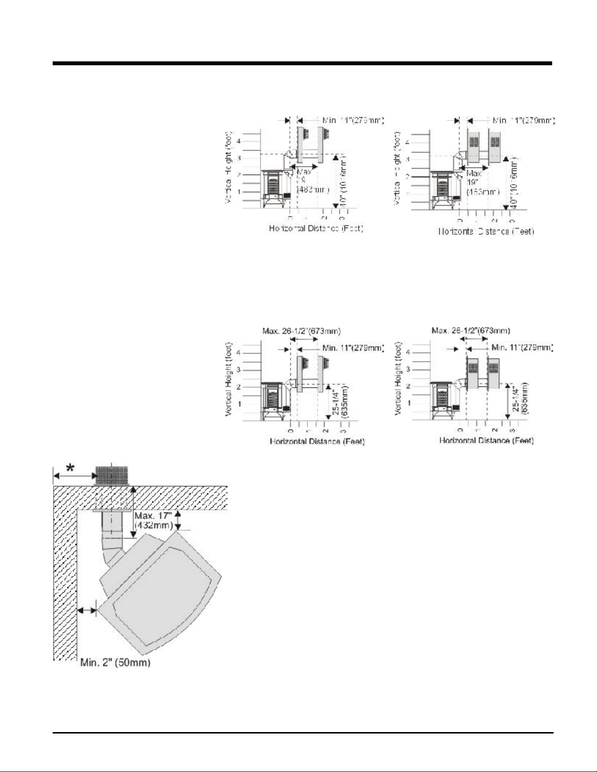
Venting Arrangements - Horizontal Terminations using Rigid Pipe
The two diagrams show all allowable
combinations of straight horizontal termination using Rigid Pipe. Restrictor position "A".
INSTALLATION
Venting Arrangements -Straight Horizontal Termination at a De-Rated BTU
The diagrams show all allowable combinations of straight horizontal termination using Rigid Pipe. Restrictor position
"A". Refer to page 27 for de-rating instructions.
Dura-Vent Snorkel Termination
Dura-Vent Snorkel Termination
Riser Vent Termination
Riser Vent Termination
*If this is an outside corner, the minimum
distance between the vent and the outside
corner is 6” (15cm). See “F” on the diagram
on page 9.
Hampton H35 Direct Vent Freestanding Gas Stove
13
Page 14

INSTALLATION
One 90o elbow = Two 45o elbows.
Horizontal Venting with Two (2) 90o Elbows
Option V H + H1
A) 3' Min. 2' Max.
B) 4' Min. 3' Max.
C) 5' Min. 4' Max.
D) 6' Min. 5' Max.
E) 7' Min. 6' Max.
F) 8' Min. 8' Max.
With these options, maximum total pipe length is 30
feet with minimum of 8 feet
total vertical and maximum
8 feet total horizontal.
Please note minimum 1
foot between 90o elbows
is required.
Lengths do not include elbow indicated
Vent restrictor position A (fully open), refer to page 8
Horizontal Venting with Two (2) 90o Elbows
One 90o elbow = Two 45o elbows.
Option H V H + H1
A) 1' Max. 2' Min. 3' Max.
B) 2' Max. 3' Min. 5' Max.
C) 3' Max. 5' Min. 6' Max.
D) 4' Max. 7' Min. 7' Max.
E) 5' Max. 9' Min. 8' Max.
With these options, max.
total pipe length is 30 feet
with min. of 9 feet total
vertical and max. 8 feet
total horizontal.
Please note min. 1 foot
between 90o elbows is
required.
Lengths do not include elbow indicated
Vent restrictor position A (fully open), refer to page 8
14 Hampton H35 Direct Vent Freestanding Gas Stove
Page 15
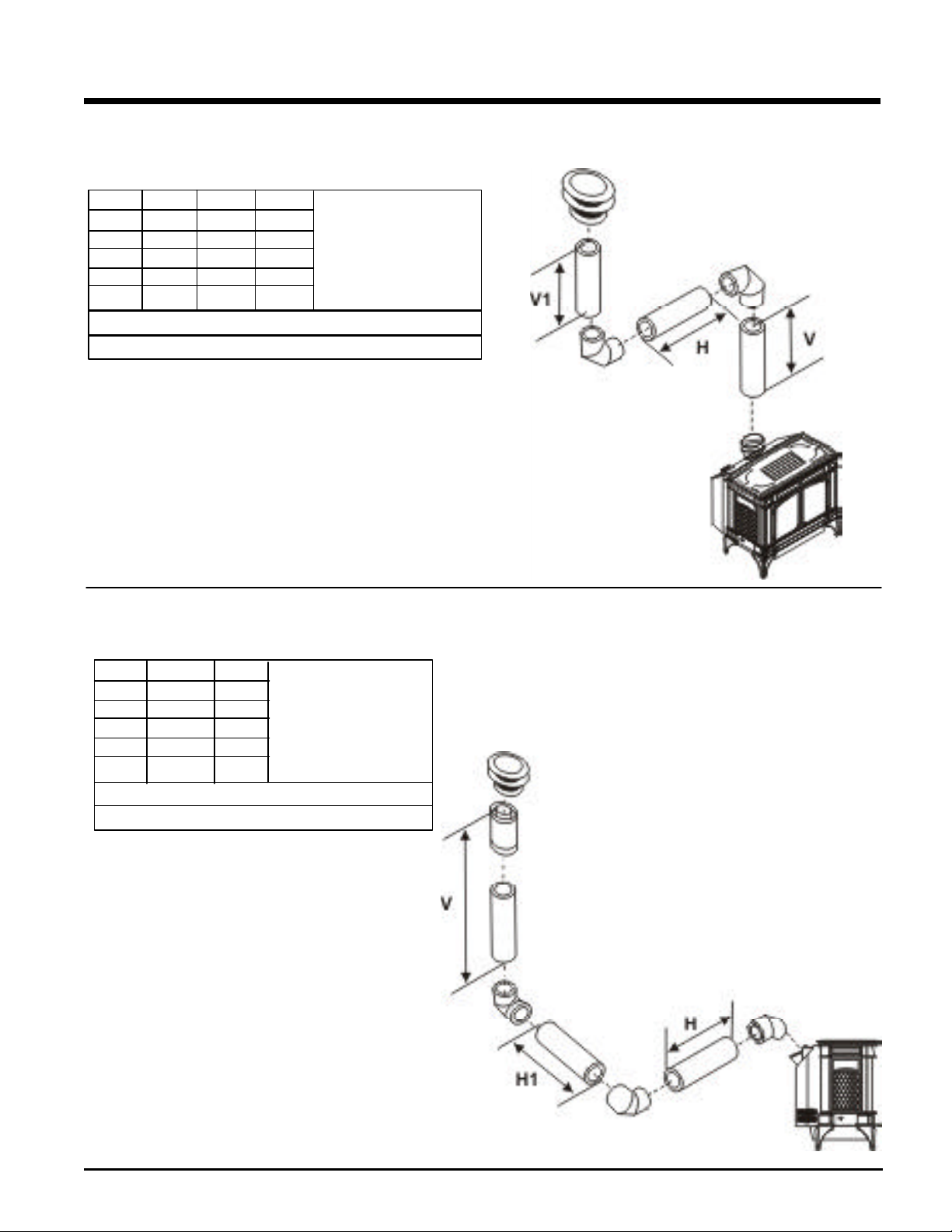
Vertical Venting with Two (2) 90o Elbows
One 90o elbow = Two 45o elbows.
INSTALLATION
Option V H V + V1
A) 1' Min. 3' Max. 2' Min.
B) 2' Min. 4' Max. 3' Min.
C) 3' Min. 5' Max. 4' Min.
D) 4' Min. 6' Max. 5' Min.
E) 5' Min. 7' Max. 6' Min.
With these options, max. total
pipe length is 30 feet with min.
of 6 feet total vertical and
max. 7 feet total horizontal.
Please note min. 1 foot
between 90o elbows is required.
Lengths do not include elbow indicated
Vent restrictor position A (fully open), refer to page 8
Vertical Venting with Two (2) 90o Elbows
One 90o elbow = Two 45o elbows.
Option H + H1 V
A) 2' Max. 2' Min.
B) 3' Max. 3' Min.
C) 4' Max. 4' Min.
D) 5' Max. 5' Min.
E) 6' Max. 6' Min.
With these options, max. total
pipe length is 30 feet with min.
of 6 feet total vertical and
max. 6 feet total horizontal.
Please note min. 1 foot
between 90o elbows is required.
Lengths do not include elbow indicated
Vent restrictor position A (fully open), refer to page 8
Hampton H35 Direct Vent Freestanding Gas Stove
15
Page 16
INSTALLATION
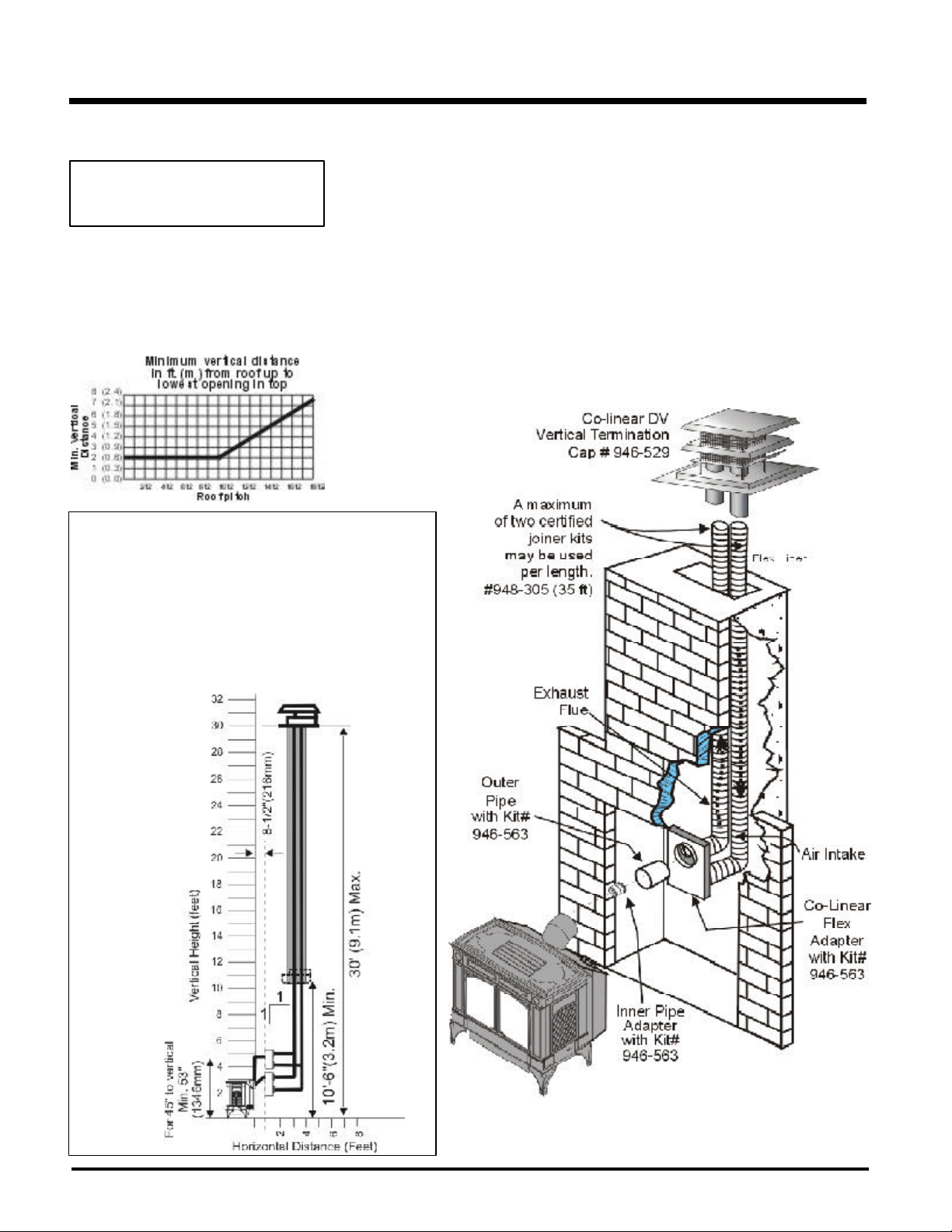
VERTICAL TERMINA TION WITH CO-LINEAR FLEX SYSTEM
THE APPLIANCE MUST NOT BE
CONNECTED TO A CHIMNEY FLUE
SERVING A SEPARATE SOLID FUEL
BURNING APPLIANCE.
This appliance is designed to be attached to two
3" (76mm) co-linear aluminium flex running the
full length of the chimney. See the Venting
Arrangements chart below for minimum and
maximum flue lengths. See chart below for
minimum distances from roof. Periodically check
that the vent is unrestricted.
Masonry chimneys may take various contours which the flexible liner will accommodate.
However, keep the flexible liner as straight as possible, avoid unnecessary bending.
The Air Intake pipe must be attached to the inlet air collar of the termination cap.
Required Parts:
Part # Description
946-529 Co-linear DV Vertical
948-305 3" Flex - 35 ft.
946-563 Co-Axial to Co-Linear Adapter Kit
Venting Arrangements - Vertical Terminations
with Co-linear Flex System for both
Residential & Manufactured Homes
into Masonry Fireplaces
The shaded area in the diagram shows the allowable
vertical terminations. Note: Must remove 4 screws from
stove collar and rotate 180o to have collar facing straight
back. Secure into place with 4 screws.
Termination Cap
which contains the following:
Co-linear Flex Adapter (270-585)
Outer Pipe (946-257)
Inner Pipe Adapter (946-219)
Alternate Approved Caps
980 Vertical Termination Cap
991 High Wind Cap
923GK
3" Co-linear Adapter with flashing
Straight Vertical Terminations
Vent Restrictors
set at 1-3/4" open
(fully open),
Posiiton "A"
16 Hampton H35 Direct Vent Freestanding Gas Stove
Page 17
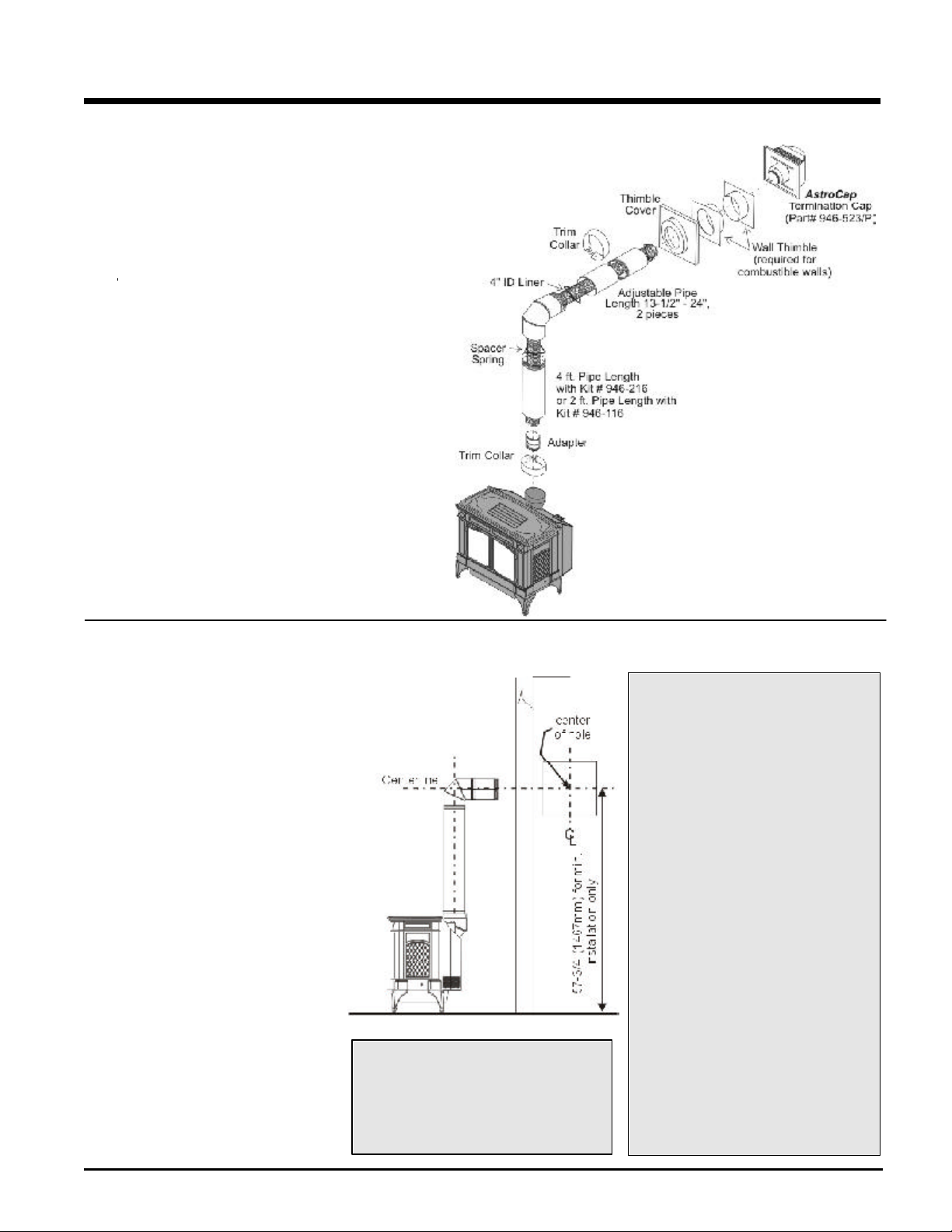
DV STOVE HORIZONTAL VENT KIT
DV 2 ft. Stove Vent Kit (Part # 946-116) and DV 4 ft. Stove Vent Kit (Part #946-216) includes all the parts
needed to install the H35 Direct Vent unit with minimum horizontal and vertical vent dimensions.
For installations that require longer vertical and/or horizontal vents use the Dura-Vent system as
shown on page 19.
Qty. Description
1) 1 Rigid Pipe Section (Kit # 946-116: 2 ft. (1.2m) length,
Kit # 946-216: 4 ft. (1.2m) length), 6-1/2" (165mm)
inside diameter
2) 1 Flex Liner, compressed aluminium 2 ply liner, 4" (102mm)
inside diameter
3) 4 spring spacers
4) 1 90 deg. Elbow
5) 1 Adjustable pipe section 13-1/2" to 24" (343mm x 610mm), 2 pcs.
6) 1 Thimble Cover
7) 1 Wall Thimble (2 pcs.)
8) 1 Adapter
9) 1 AstroCap Termination Cap
10) 2 Trim Collars
11) 1 tube of Mill-Pac, high temperature sealant
12) 12 Screws, #8 x 1/2" Self tapping, Stainless Steel
13) 14 Screws, #8 x 1/2" Self tapping, Black
14) 4 Screws #8 x 1-1/2" Drill Point, Black
15) 4 Screws #8 x 1-1/2" Drill Point, Stainless Steel
16) 8 Wood screws #8 x 1"
Required but not included in above Kit:
45o Elbow (Part #: 946-214)
INSTALLATION
Note:
a) Liner sections should be con-
tinuous without any joints or
seams.
b) This is an approved system,
therefore components in this
system must not be substituted for any other manufacturer's products.
DV STOVE HORIZONTAL VENT KIT (#946-116 & #946-216) INSTALLATION
Review the following sequence of instructions
which are typical of most installations. The
sequence may vary depending on wall thickness. Refer to pages 9 to 16 for vent
location and clearance dimensions, and
page 8 to set the Vent Restrictor to the
correct position.
1) Set the unit in its desired location. Check to
determine if wall studs will be in the way of
the venting system, adjust location until all
clearances are met and there are no obstructions.
Note: A 1-1/2"(38mm) clearance around
the outer pipe must be maintained
except that only a 1" (25mm) clearance is needed at the termination
end.
IMPORTANT:
Do not locate termination hood
where excessive snow or ice buildup may occur. Be sure to check vent
termination area after snow falls,
and clear to prevent accidental
blockage of venting system. When
using snow blowers, make sure
snow is not directed towards vent
termination area.
2) Assemble a trial fit to determine the vertical center-line for the vent termination.
a) Cut a 9-1/2" x 9-1/2" (241mm x 241 mm)
square hole on both the interior and
exterior wall.
b) Install wall thimbles on both interior
and exterior wall with 4 wood screws
(#8 x 1") per thimble.
c) Attach the 2 piece adjustable pipe
section to the vent terminal and slide
into position from the exterior. The
larger diameter end of the adjustable pipe goes to the vent
terminal.
d) Install the 90o elbow onto the adjusta-
ble pipe to determine the vertical
centerline.
Note: if the centerline cannot be
met, the adjustable sections will
have to be cut.
e) Cut the 4 ft. section of rigid pipe to
length. Attach the 45o elbow to the
rigid pipe, and ensure that the pipe
length when cut (with the 45o elbow)
will seat onto both the starter collar
and the 90o elbow. Crimped sec-
tion of rigid pipe seats into the 90
elbow. Only cut the uncrimped
side of pipe.
Dismantle all pipe sections including vent
terminal.
o
Hampton H35 Direct Vent Freestanding Gas Stove
17
Page 18
INSTALLATION
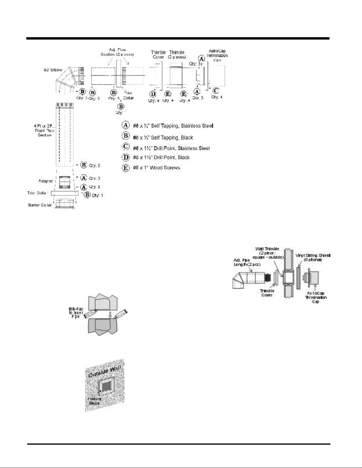
3) Attach the 4" dia. flex liner to the vent
terminal ensuring that the flex overlaps the
collar of the vent terminal by a minimum of
1-3/8"(35mm). Use Mill-Pac to seal and
secure with 3 of the #8 x 1/2" screws
(stainless steel).
4) Attach the adjustable pipe section to the
vent terminal using Mill-Pac and/or high
temperature silicone and attach with 3 of
the #8 x 1/2" screws (stainless steel).
Hint: Apply the sealant (Mill-Pac and/or high
temperature silicone) to the outer pipe before
connecting the inner pipe.
Note: The pipe
seam
should be
facing
down.
Note: To make the installation more aes-
thetically pleasing, we recommend framing out a square that
the cap can be mounted on.
Note: If installing ter-
mination on a
siding covered
wall, a vinyl siding standoff or
furring strips
must be used to
ensure that the
termination is
not recessed into the siding. For
vinyl siding standoff installation
refer to the Dura-Vent Termination instructions.
5) Slide the partially connected pipe and vent
terminal assembly through the wall thimbles (from the exterior into the interior) and
secure the cap to the exterior wall with 4
of the supplied screws (#8 x 1-1/2" drill
point, stainless steel). Note: pilot holes will
need to be drilled through the wall thimble
on all 4 corners.
Note: The four screws provided for the
vent cap should be replaced with
appropriate fasteners for stucco,
brick, concrete, or other types of
sidings.
6) A bead of non-hardening mastic should be
run around both the termination and vinyl
siding standoff to prevent water from
entering and to make a tight seal between
the cap and the standoff.
7) Stretch the 4" dia. flex liner out fully and get
a trial fit of the liner onto the 4" dia. starter
collar.
8) Cut the 4" dia. flex liner to the desired size.
Hint: leave an extra 12" to 16" of length, this
will make the final assembly easier to work
with.
9) Secure the 4" dia. flex liner to the 4" adapter
with Mill-Pac and 3 of the #8 x 1/2" screws
(stainless steel).
10)Slide the decorative Thimble Cover over
the pipe sections and secure with 4 screws
(#8 x 1-1/2" drill point, black) to the wall.
11)Slide the 90o elbow (crimp end up), the 45
elbow and the 4 ft. pipe section (crimp end
up) over the 4" dia. flex liner.
12)Install the spring spacers onto the pipe
sections.
13)Secure the 4" dia. flex liner with adapter
onto the stove collar. Put a bead of Mill-Pac
around the appliance adapter and secure
with 3 screws (#8 x 1/2, stainless steel).
14)Attach the 45o elbow onto the starter collar
by sealing with Mill-Pac and/or high temperature silicone and securing with 3 of the
#8 x 1/2" (black) screws.
15)Attach the pipe section to the 45o elbow by
sealing with Mill-Pac and/or high temperature silicone and securing with 3 of the #8
x 1/2" screws (black). Pipe seams should
be facing the wall.
16)Attach the 90o elbow onto the pipe section
by sealing with Mill-Pac and/or high temperature silicone and securing with 3 of the
#8 x 1/2" screws (black).
17)Slide the adjustable pipe section onto the
90o elbow. Slide the trim collar over the
adjustable pipe sections to cover the joint
of the telescopic section.) The flex may
have to be compressed back in order for
the adjustable pipe to properly mate to the
elbow. Seal with Mill-Pac and/or high
temperature silicone and secure with 3 of
the #8 x 1/2" screws (black). Pipe seams
facing down.
18)Install the trim collar over the starter collar
and secure with a #8 x 1/2" screw (black).
If the pipe needs to be touched up, use only
Stove Brite High Temperature Metallic Black
Stove Paint.
NOTE: All inner joints must be sealed
with Mill-Pac. All outer joints may
be sealed with high temperature
silicone.
o
18 Hampton H35 Direct Vent Freestanding Gas Stove
Page 19
DURA-VENT TERMINA TION KIT
INSTALLATION
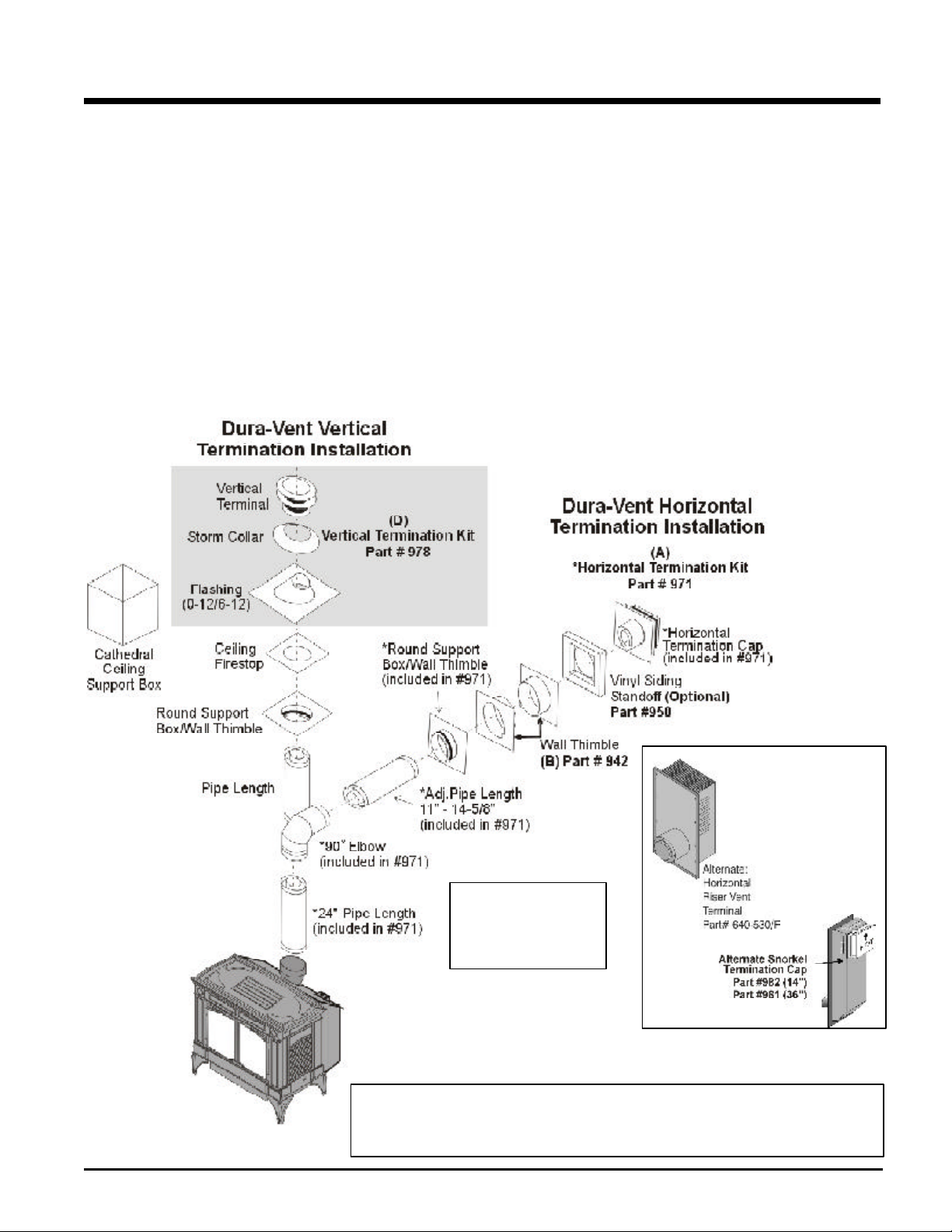
Planning Your Dura-Vent
Installation
There are two basic types of Dura-Vent Direct
Vent System installations: horizontal termination and vertical termination. Confirm the maximum horizontal run and maximum vertical rise
from the diagrams on pages 12-16.
When planning your installation, it will be necessary to select the proper length of vent pipe
for your particular requirements. For horizontal
installations, determine the minimum clearance
from the rear of the unit to the wall. It is also
important to note the wall thickness. (The wall
thimble is suitable for 2 x 4 or 2 x 6 wall
construction.) Select the amount of vertical
rise desired for "vertical-to-horizontal" type
installations.
Warning: Always maintain required
clearances (air spaces) to nearby
combustibles to prevent a fire hazard. Do not fill air spaces with insulation.
The minimum clearance requirements between
the outer wall of the vent pipe and nearby
combustible surfaces is 1-1/4 inch. Be sure to
check the vent termination clearance require-
ments from decks, windows, soffits, gas
regulators, air supply inlets and public walkways as specified in the Exterior Vent Terminal Locations on page 9 and in your local
building codes.
To determine the length of vent pipe required
for vertical installations, measure the distance from the unit flue outlet to the ceiling, the
ceiling thickness, the vertical rise in an attic
or second storey, and allow for sufficient
vertical height above the roof line.
For multi-storey applications, fire stops are
required at each floor level. If an offset is
needed, additional pipe, elbows and supports will be required.
Do not exceed the maximum number of elbows. One 90o for horizontal terminations
and two 45o for vertical termination.
The FPI AstroCap
Vent® and Direct Vent GS.
The FPI AstroCapTM is a proprietary trademark of FPI Fireplace Products International Ltd.
Dura-Vent® and Direct Vent GS are registered and/or proprietary trademarks of Simpson Dura-Vent
Co. Inc.
Hampton H35 Direct Vent Freestanding Gas Stove
Alternate
Horizontal
Termination Caps
Dura-Vent Basic
Horizontal Kit # 970
1 90o Elbow
1 Wall Thimble Cover
1 Horiz. Sq. Term. Cap
TM
is certified for installations using FPI venting systems as well as Simpson Dura-
19
Page 20
INSTALLATION
DURA-VENT VENTING
COMPONENTS
The Simpson Dura-Vent Direct Vent System
offers a complete line of component parts for
installation of both horizontal and vertical installation. Many items are offered in decorative
black, as well as galvanized finish. The galvanized pipe and fittings are used for concealed
locations such as attics or where corrosion is
a factor, such as above the roof line. Decorative brass trim kits are available for both wall
thimbles and ceiling support boxes.
Part # Description
971 Horiz. Termination Kit includes: 90o black
elbow, wall thimble cover, horiz. square
termination cap, 24" black pipe, 11" -14"
5/8" adjustable black pipe
970 Basic Horiz. Termination Kit includes:
90o black elbow, wall thimble cover,
horiz. square term. cap
978 Vert. Termination Kit includes 0/12 - 6/
12 pitch adjustable flashing, storm collar, low profile term. cap
908B 6" Pipe Length-Black
907B 9" Pipe Length-Black
906 12" Pipe Length Galv.
906B 12" Pipe Length-Black
904 24" Pipe Length Galv.
904B 24" Pipe Length-Black
903 36" Pipe Length Galv.
903B 36" Pipe Length-Black
902 48" Pipe Length Galv.
902B 48" Pipe Length-Black
911B 11"-14 5/8" Adj. Pipe Length-Black
917B 17"- 24" Adj. Pipe Length Black
945 45O Elbow Galv.
945B 45O Elbow-Black
945G 45O Elbow-Swivel Galv.
945BG 45O Elbow-Swivel-Black
990 90O Elbow Galv.
990B 90O Elbow-Black
990G 90O Elbow-Swivel Galv.
990BG 90O Elbow-Swivel-Black
991 High Wind Term. Cap (Vertical)
980 Vertical Term. Cap
984 Horiz. Sq. Term. Cap
985 Horiz. Sq. High Wind Termination
Cap
982 Snorkel-14" Rise Term.Cap
981 Snorkel-36" Rise Term.Cap
940 Wall Thimble-Support/Box
941 Cathedral/Ceiling-Support/Box
3951 Brass Trim-WallThimble/Ceiling Support
963 Firestop Spacer
943 Flashing 0/12-6/12
943S Flashing 7/12-12/12
953 Storm Collar
950 Vinyl Siding Standoff
988 Wall Strap
942 Wall Thimble
Parts not supplied by Dura-Vent
946-506/P Vent Guard (Optional)
640-530 Riser Vent Terminal (Optional)
948-128 Vinyl Siding Shield for Riser
Vent Terminal
946-228 Horizontal Square Termination Cap
You will require the following components with
your new Direct Vent Freestanding Gas Stove.
Please review your product to make sure you
have everything you need. In the event that you
are missing any part, contact your dealer.
Note: These are the minimum pieces
required. Other parts may be required for your particular installation. See above for a list of vent
parts.
If installing termination on a siding covered wall,
a vinyl siding standoff or furring strips can be
used in order to ensure that the termination is
not recessed into siding.
The vinyl siding standoff is required for walls
with vinyl siding.
Minimum components for a Dura-Vent
Horizontal Installation:
A) Dura-Vent Horizontal Termination Kit
B) Wall Thimble (required for combustible
walls)
Minimum components for a Dura-Vent
Vertical Termination:
D) Dura-Vent Vertical Termination Kit. See
above for pipe lengths.
DURA-VENT
HORIZONTAL
INSTALLATIONS
1) Set the unit in its desired location. Check to
determine if wall studs or roof rafters are
in the way when the venting system is
attached. If this is the case, you may want
to adjust the location of the unit.
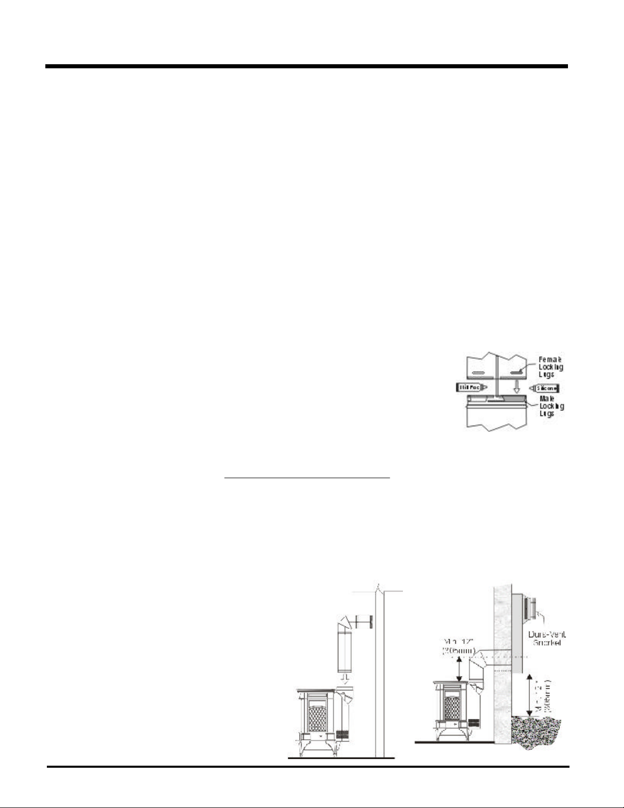
2) Direct Vent pipe and fittings
are designed with special
twist-lock connections to
connect the venting system to the appliance flue
outlet. A twist-lock appliance adapter is installed
on the unit at the factory.
Assemble the
desired combination of pipe
and elbows to
the appliance
adapter with
pipe seams
oriented to-
wards the wall or ceiling, as much out of
view as possible. The final positioning of
the pipe and 90o elbow assembly is determined by the mounting orientation of the
adapter on the stove and twist-locked for
a solid connection.
Note:
a) Twist-lock procedure: Four indenta-
tions, located on the female ends of
pipes and fittings, are designed to slide
straight onto the male ends of adjacent
pipes and fittings, by orienting the four
pipe indentations so they match and
slide in to the four entry slots on the
male ends (diagram 1). Push the pipe
sections completely together, then
twist-lock one section clockwise approximately one-quarter turn, until the
two sections are fully locked. The female locking lugs will not be visible from
the outside on the Black Pipe or fittings.
They may be located by examining the
inside of the female ends. Apply sealant "Mill-Pac" to inner pipe and high
temp silicone sealant to outer pipe on
every twist-lock joint.
Diagram 1:
Hint: Apply
silicone to
female end.
b) Horizontal runs of vent must be sup-
ported every three feet. Wall straps are
available for this purpose.
c) Snorkel Terminations:
For installations requiring a vertical rise
on the exterior of the building, 14-inch
and 36-inch tall Snorkel Terminations
and the Riser Vent as shown in Dia. 2
& 2a are available. Follow the same
installation procedures as used for
standard Horizontal Termination. NEVER install the snorkel upside down.
*As specified in CGA
B149 Installation Code.
Local codes or regulations may require different clearances.
Diagram 2
20 Hampton H35 Direct Vent Freestanding Gas Stove
Page 21
INSTALLATION
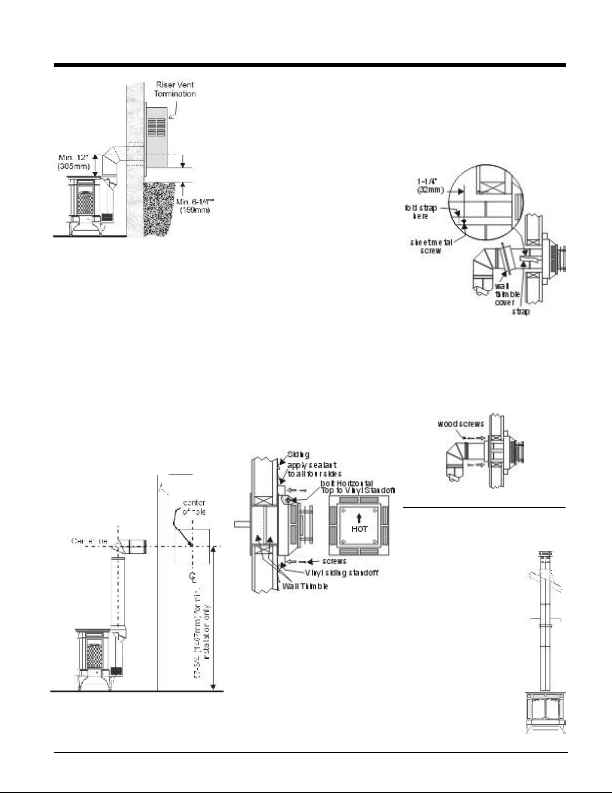
Diagram 2a
Below Grade Snorkel Installation
If the Snorkel Termination must be installed
below grade, i.e. basement application,
proper drainage must be provided to prevent water from entering the Snorkel Termination. Refer to Dura-Vent Installation
instructions for details. Do not attempt to
enclose the Snorkel within the wall, or any
other type of enclosure.
3) With the pipe attached to the stove, slide the
stove into its correct location, and mark the
wall for a 10" x 10" (inside dimensions)
square hole. The center of the square hole
should line up with the centerline of the
horizontal pipe, as shown in diagram 3. Cut
and frame the 10 inch square hole in the
exterior wall where the vent will be terminated. If the wall being penetrated is constructed of non-combustible material, i.e.
masonry block or concrete, a 7" diameter
hole is acceptable.
the vent to run downward. This could
cause high temperatures and may
present the possibility of a fire.
b) The location of the horizontal vent ter-
mination on an exterior wall must meet
all local and national building codes,
and must not be blocked or obstructed.
For External Vent Terminal Locations,
see diagram on page 9.
4) If installing the vent termination to a wall
with vinyl siding, the Vinyl Siding Standoff
must be used. Attach the Vinyl Siding
Standoff to the Horizontal Vent Termination, but first run a bead of non-hardening
mastic around its outside edges, so as to
make a seal between vent cap and the
standoff. Install the Vinyl Siding Standoff
(Part # 950) between the vent cap and the
exterior wall and attach with the four wood
screws provided. Seal around the Vinyl
Siding Standoff on all four sides. Diagram
6. The arrow on the vent cap should
be pointing up. Insure that the 1-1/4"
clearances to combustible materials are
maintained. See diagram 4.
Note: If installing termination on a sid-
ing covered wall, a vinyl siding
standoff or furring strips must be
used to ensure that the termination is not recessed into the siding. The four wood screws provided should be replaced with appropriate fasteners for stucco,
brick, concrete, or other types of
sidings.
sheet metal strips extending from the vent
cap assembly into the outer wall of the vent
pipe. Use the two sheet metal screws
provided to connect the strips to the pipe.
Bend any remaining portion of the sheet
metal strip back towards the vent cap, so
it will be concealed by the decorative wall
thimble cover. See diagram 5.
Diagram 5
7) Install wall thimble in the center of the 10"
square and attach with wood screws.
8) Slide the decorative wall thimble up to the
wall surface being careful not to scratch
the paint and attach with screws provided.
Apply decorative brass or chrome trim if
desired. See diagram 6.
Diagram 3
Note:
a) The horizontal run of vent should have
a 1/4 inch rise for every 1 foot of run
towards the termination. Never allow
Hampton H35 Direct Vent Freestanding Gas Stove
Diagram 4
5) Before connecting the horizontal run of
vent pipe to the vent termination, slide the
black decorative wall thimble cover over the
vent pipe, then slide the Wall Thimble (Part
# 942) over the vent pipe.
6) Slide the appliance and vent assembly towards the wall carefully inserting the vent
pipe into the vent cap assembly. It is important that the vent pipe extends into the vent
cap a sufficient distance so as to result in
a minimum pipe overlap of 1-1/4 inches.
Secure the connection between the vent
pipe and the vent cap by attaching the two
Diagram 6
DURA-VENT VERTICAL
TERMINATION
1) Maintain the 1-1/4" clearances
(air spaces) to combustibles
when passing through ceilings,
walls, roofs, enclosures, attic rafter, or other nearby combustible
surfaces. Do not pack air spaces with insulation. Check page
10 for the maximum vertical rise
of the venting system and the
maximum horizontal offset limitations.
2) Set the gas appliance in its desired
location. Drop a plumb bob
down from the ceiling to the
position of the appliance flue
exit, and mark the location
where the vent will penetrate the ceiling. Drill a small
hole at his point. Next, drop
Diagram 7
21
Page 22
INSTALLATION
a plumb bob from the roof to the hole
previously drilled in the ceiling, and mark the
spot where the vent will penetrate the roof.
Determine if ceiling joists, roof rafters or
other framing will obstruct the venting system. You may wish to relocate the appliance
or to offset, as shown in diagram 8 to avoid
cutting load bearing members.
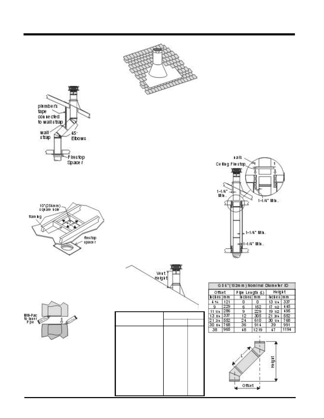
Diagram 8
3) To install the Round Support Box/Wall Thimble in a flat ceiling, cut a 10 inch square hole
in the ceiling centred on the hole drilled in
Step 2. Frame the hole as shown in diagram
9.
Diagram 10: The upper half of the flashing is
installed under the roofing material and not
nailed down until the chimney is installed.
This allows for small adjustments.
6) Continue to assemble pipe lengths.
Note: If an offset is necessary in the
attic to avoid obstructions, it is
important to support the vent pipe
every 3 feet, to avoid excessive
stress on the elbows, and possible separation. Wall straps are
available for this purpose. See
diagram 5.
Galvanized pipe and elbows may be utilized in the attic as well as above the
roofline. The galvanized finish is desirable
above the roofline due to its higher corrosion resistance.
7) Ensure vent is vertical and secure the base
of the flashing to the roof with roofing rails,
slide storm collar over the pipe section and
seal with a mastic.
8) Install the vertical termination cap by twist
locking it.
Notes:
a) For multistorey vertical installations, a
Ceiling Fire stop (Part # 963) is required
at the second floor, and any subsequent floor. Diagram 12. The opening
should be framed to 10 " x 10" inside
dimensions, in the same manner as
shown in diagram 9.
b) Any occupied areas above the first
floor, including closets and storage
spaces, through which the vertical
vent passes, must be enclosed.
Diagram 9
4) Assemble the desired lengths of black pipe
and elbows necessary to reach from the
appliance adapter up though the Round
Support Box. Insure that all pipes and
elbow connections are in the fully twistlocked position and sealed.
Hint: Apply the
sealant (Mill-Pac
and/or high temperature silicone) to the outer pipe before
connecting the
inner pipe.
5) Cut a hole in the roof centred on the small
drilled hole placed in the roof in Step 2. The
hole should be of sufficient size to meet the
minimum requirements for clearance to
combustibles of 1-1/4". Slip the flashing
under the shingles (shingles should overlap half the flashing) as per diagram 10.
Continue to add pipe sections through the
flashing until the height of the vent cap
meets the minimum height requirements
specified in diagram 11 or local codes.
Note that for steep roof pitches, the vertical height must be increased. A poor
draft, or down drafting can result from
high wind conditions near big trees or
adjoining roof lines, in these cases, increasing the vent height may solve the
problem.
Diagram 11
Roof Pitch Minimum Vent Height
Feet Meters
flat to 7/12 2 0.61
over 7/12 to 8/12 2 0.61
over 8/12 to 9/12 2 0.61
over 9/12 to 10/12 2.5 0.76
over 10/12 to 11/12 3.25 0.99
over 11/12 to 12/12 4 1.22
over 12/12 to 14/12 5 1.52
over 14/12 to 16/12 6 1.83
over 16/12 to 18/12 7 2.13
over 18/12 to 20/12 7.5 2.29
over 20/12 to 21/12 8 2.44
Diagram 12
Offset Chart
22 Hampton H35 Direct Vent Freestanding Gas Stove
Page 23
INSTALLATION
CONVERTING A
CLASS-A METAL
CHIMNEY OR
MASONRY CHIMNEY
T O A DIRECT VENT
SYSTEM
There are two different types of direct vent
conversion systems listed below. Follow the
appropriate directions for your installation.
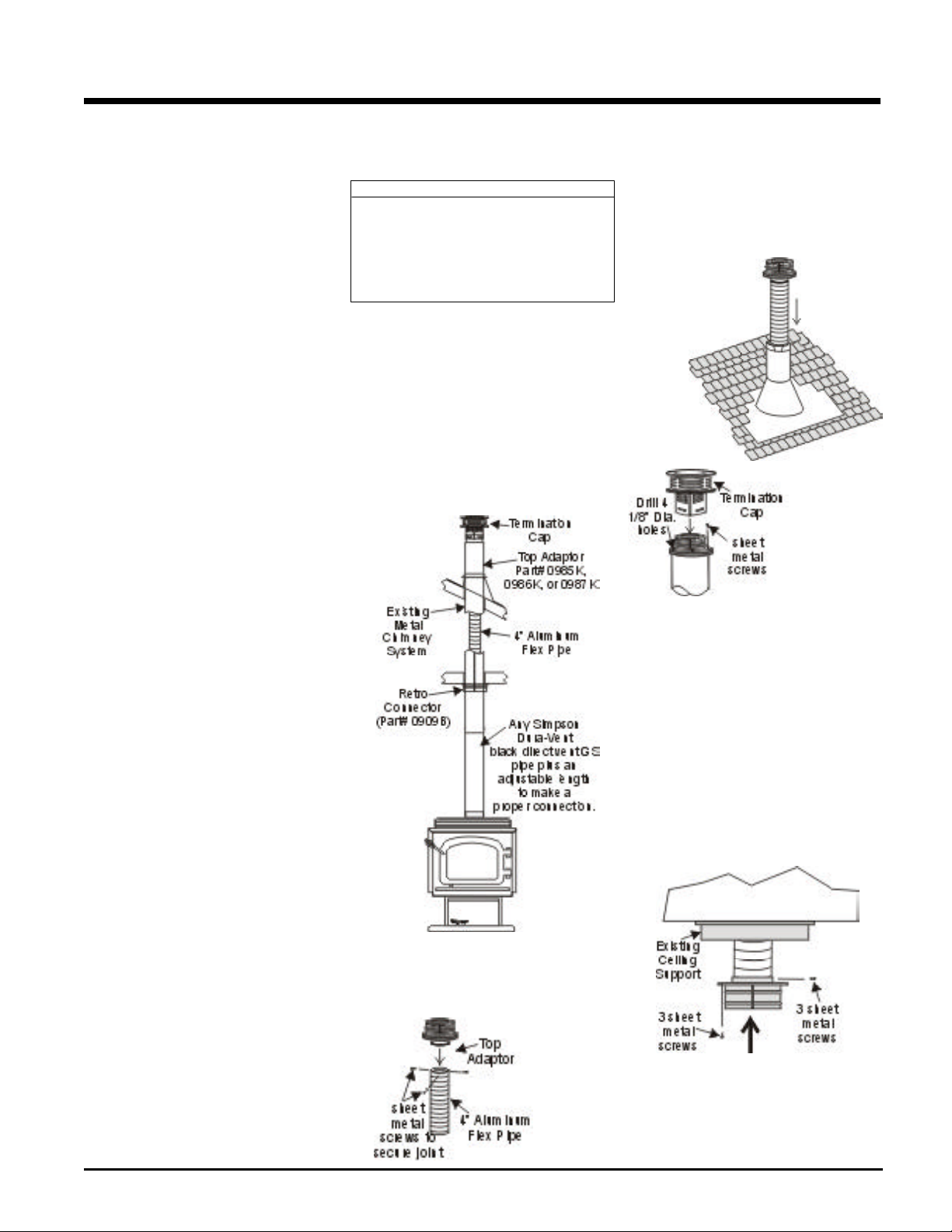
A) Through an existing factory built metal
chimney going through the ceiling: A typical
conversion of this type is shown in diagram
1. The concept of direct vent conversion is
to connect an adaptor to an Underwriters
Laboratories (UL) listed 4 inch diameter
aluminum flex pipe which is then passed
down through the center of the existing
metal chimney system. Three sizes of Top
Adaptors are available from Simpson DuraVent. The Retro Connector (909B) is attached to the bottom of the flex pipe. The
Top Adaptor and the Retro Connector are
attached to the existing chimney with sheet
metal screws. The appliance is then connected to the chimney with appropriate
black direct vent pipe and an adjustable
length section.
B) Through the wall of an existing masonry
chimney: A typical conversion of an existing masonry chimney is shown in Diagram
6. A Top Adaptor (985K) and Flashing are
used at the top of the masonry chimney.
The 4 inch aluminum liner is connected to
the adaptor and is passed down the chimney and out through the masonry wall and
attached to the Retro Connector (909B).
The Retro Connector is attached to the
masonry wall and then connected to the
direct vent pipe leading to the appliance.
Prior to installation and connection of the
vent system to a factory-built or masonry chimney, the chimney must be inspected and thoroughly cleaned by a
qualified service person, such as a certified chimney sweep or home inspection service.
The direct vent system must not be
connected to a damaged factory-built or
masonry chimney.
leaky chimney condition exists. Do not
operate the appliance until the problem
is corrected.
Appoved for US Installations Only
The use of an existing chimney as an air
intake is not covered under the ANSI
Z21.88b-1999, CSA 2.33b-M99 test methods and the resulting ITS/WHI product
certification. The code Authority Having
Jurisdiction must be consulted prior to
proceeding with this installation method.
Converting a Factory Built Metal
Chimney
1) Remove the existing chimney cap.
2) Measure the distance from the top end of
the chimney to the bottom of the ceiling
support box, add 3" (76mm) to this measurement, and cut a section of the 4" flex pipe
to that length (the flex should already be
extended to its nominal length).
Diagram 1
3) Connect the end of the flex pipe section to
the underside of the Top Adaptor using 3
sheet metal screws. Diagram 2.
4) Pass the flex pipe down through the center
of the chimney system, and center the
adaptor on the top of the chimney pipe. Drill
four 1/8" diameter holes through the adaptor and into the chimney top. Insure that you
are in fact, drilling into the metal on the
chimney. Twist-lock the Termination Cap
(Part# 980 or 991) onto the Adaptor. (Diagram 3 and 4).
Diagram 3
Diagram 4
5) Pull the flex pipe down through the ceiling
support box, until it protrudes approximately 3" (76mm). Connect the flex pipe to the
Retro Connector by slipping it into the
4-3/4" diameter sleeve on the top side of the
Connector. Use 3 sheet metal screws to
assemble these two parts.
6) Push the flex pipe back up into the ceiling
support box, center the Retro Connector,
and attach it to the support box, or decorative sleeve for double wall solid packed
pipe, with the sheet metal screws (supplied). The holes in the Retro Connector are
pre-punched. Diagram 5.
For factory built, zero clearance, and masonry chimneys cleanout doors and caps
or plugs for cleanout tee fittings and ash
dumps shall be secured in place and
sealed before installing a Direct Vent
system within the chimney.
If the appliance shuts off during operation, contact a qualified service person to
determine if a negative pressure and/or
Hampton H35 Direct Vent Freestanding Gas Stove
Diagram 2
Diagram 5
7) The connection between the appliance
and the Retro Connector may be completed
with sections of black direct vent pipe,
together with an adjustable length.
23
Page 24
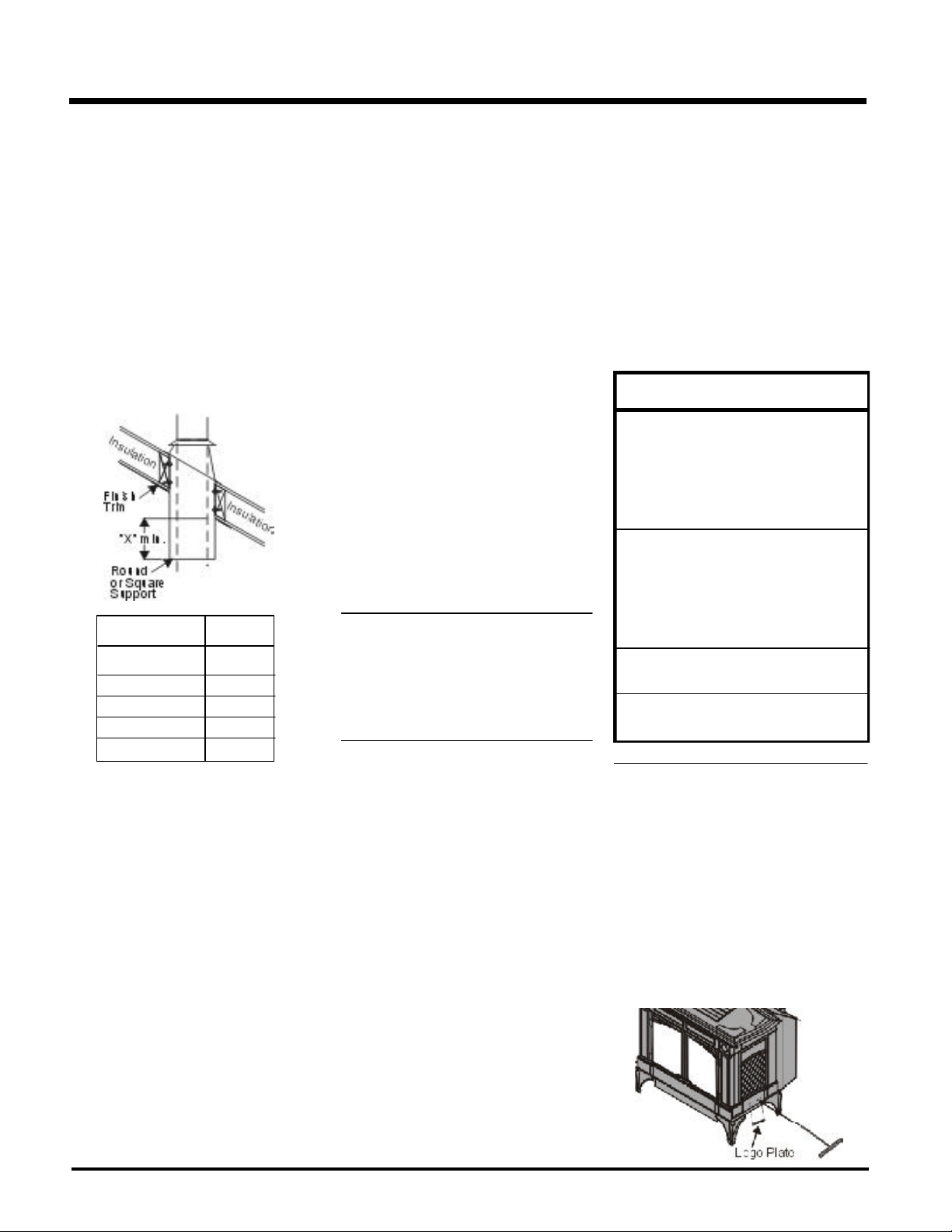
INSTALLATION
CATHEDRAL CEILINGS
Round Support (RDS) &
Square Support (SQS)
If your home has a cathedral ceiling (no attic
space between the ceiling and the roof), install
the chimney and support as follows.
1) Situate the chimney in a convenient location as near as possible to the appliance
outlet. Cut and frame a hole in the roof for
the support. The sides of this hole must be
vertical with 1 1/4" clearance.
2) Place the support in the opening. Lower it
to the correct height as determined by the
table and diagram below.
Slope "X"
0/12 -2/12 4"
2/12 -7/12 5-1/2"
7/12 -12/12 6-3/4"
12/12 -24/12 7-1/2"
24/12+ 12-1/2"
Using a level, make sure the support is
vertical. If the support extends above the
roof, cut it flush with the top of the roof.
Nail the support to the frame opening
using (8) 3" spiral nails or #8 x 1-1/2"
screws.
Note: If you are using a 6" square sup-
port you may find it difficult to
screw it in place because it is fairly
small inside.
Simpson Dura-Vent has provided angle
brackets with this support which can be
screwed to the outside of the support box
and nailed to surrounding framing as required. Use a minimum of four #8 x 1/2"
screws per bracket. In some cases these
brackets may need to be trimmed (e.g.: to
fit under a flashing). Place the Finish
Collar around the support and fasten it to
the ceiling using the screws provided.
3) Use appropriate roof flashing. Place the
flashing under the upper shingles and on
top of the lower shingles approximately
half of the flashing should be under the
shingles.
4) Assemble the desired lengths of Black Pipe
and Elbows necessary to reach from the
appliance adapter up through the support
box and flashing to proper height as per
Dia. 12, local codes or page 10. Ensure that
all pipe and elbow connections are in their
fully twist lock position.
5) Ensure vent is vertical and secure flashing
to the roof with roofing nails. Slide the
storm collar over the pipe section and seal
with a mastic.
6) Twist lock the vent cap on to the last
section.
Support Extensions - Round
(RDSE)
or Square (SQSE)
Steep pitched cathedral ceilings may require
the use of a support extension. This piece fits
down inside the support and can be adjusted
to increase the support's length by up to 22".
The extension is attached to the support using
the eight metal screws provided. Be sure there
is at least a 2 inch overlap where the extension
joins the support.
HIGH ELEV ATION
This unit is approved in Canada for altitude to 4500
ft. (CAN/CGA-2.17-M91). For Natural Gas installations above 4500 ft. follow current CAN/CGAB149.1.
GAS CONNECTION
The gas connection is a 3/8" NPT 90o elbow.
The gas line can be rigid pipe or to make
installation easier, use a listed flexible connector and/or copper tubing if allowed by local
codes. Since some municipalities have additional local codes it is always best to consult
with your local authorities and the CAN/CGA
B149 installation codes.
For USA installations follow local codes and/or
the current National Fuel Gas Code, ANSI
Z223.1.
When using copper or flex connectors use
only approved fittings. Always provide a union
so that gas lines can be easily disconnected for
burner and/or valve servicing. Flare nuts for
copper lines and flex connectors are usually
considered to meet this requirement.
IMPORTANT: ALWAYS CHECK FOR
GAS LEAKS WITH A SOAP AND
WATER SOLUTION OR GAS LEAK
DETECTOR. DO NOT USE OPEN
FLAME FOR LEAK TESTING.
Note: Prior to any pressure testing of
the gas supply piping system that
exceeds test pressures of 1/2 psig,
this appliance must be disconnected from the piping system. If test
pressures equal to or less than 1/
2 psig are used then this appliance
must be isolated from the piping
system by closing its individual
manual shut-off valve during the
testing.
SYSTEM DATA - H35
For 0 to 4500 feet altitude
Natural Gas
Max. Input Rating 36,000 Btu/h
Min. Input Rating 18,000 Btu/h
Orifice Size #33 DMS
Convertible to:
Max. Input Rating 30,000 Btu/h
Min. Input Rating 14,300 Btu/h
Orifice Size #37 DMS
Propane
Max. Input Rating 34,000 Btu/h
Min. Input Rating 17,500 Btu/h
Orifice Size #51 DMS
Convertible to:
Max. Input Rating 28,500 Btu/h
Min. Input Rating 15,000 Btu/h
Orifice Size #52 DMS
Supply Pressure
Natural Gas min. 5.0" w.c.
Propane min. 12.0" w.c.
Manifold Pressure
Natural Gas 3.8" +/- 0.2" w.c.
Propane 11" +/- 0.2" w.c.
AERA TION
ADJUSTMENT
The burner aeration is factory set but may need
adjusting due to either the local gas supply, air
supply or altitude.
Natural Gas 1/4" (6.4 mm)
Propane 3/8" (9.5 mm)
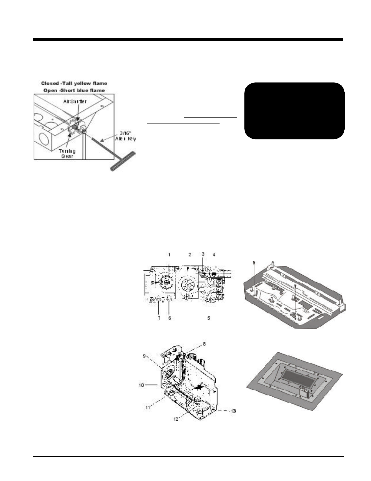
The aeration adjustment gears are located on
the right side of the burner box. Remove the
Hampton Logo plate on the right side of the unit
to access the adjustment gears.
24 Hampton H35 Direct Vent Freestanding Gas Stove
Page 25
INSTALLATION
To adjust the aeration: use the allen key to turn
the turning gear which will adjust the air shutter.
Open the air shutter for a blue flame or close it
for a yellower flame.
Clockwise to open,
counter-clockwise to close.
Caution: Carbon will be produced if the
air shutter is closed too much.
Note: Any damage due to carboning re-
sulting from improperly setting
the aeration controls is NOT covered under warranty.
Note: Aeration Adjustment should only
be performed by an authorized
Hampton Installer at the time of
installation or service.
4) Light the pilot and turn the valve to "ON"
position. Read manometer.
5) The pressure check should be carried out
with the unit burning and the setting should
be within the limits specified on the safety
label.
6) When finished reading manometer, turn off
the gas valve, disconnect the hose and
tighten the screw (clockwise) with a 1/8"
flat screwdriver. Note: Screw should be
snug, but do not over tighten
Valve Description
1) Gas cock knob
2) Manual high/low adjustment
3) Pilot Adjustment
4) Thermocouple Connection
5) Main Operator
6) Outlet Pressure Tap (Manifold Pressure)
7) Inlet Pressure Tap (Supply Pressure)
8) Pilot Outlet
9) Main Gas Outlet
10)Flange Securing Screw Holes
11)Alternative TC Connection Point
12)Thermoelectric Unit
13)Additional Valve Mounting Hole
CONVERSION FROM
NA TURAL GAS TO
PROPANE
THIS CONVERSION MUST
BE DONE BY A
QUALIFIED GAS
FITTER IF IN DOUBT DO
NOT DO THIS
CONVERSION !!
Conversion Kit #730-969 Contains:
Qty. Part # Description
1 910-018 SIT Conversion Kit-
50% Turndown LP
1 910-037 LP Injector (Pilot Orifice)
1 904-645 Burner Orifice #51
1 908-528 Red "PROPANE" label
1 908-255 Label "Converted to Propane"
1 Instruction Sheet
1) Shut off the gas supply.
2) Lift off the Cast Top and remove the glass
front (see page 36) and carefully remove
the logs and lava rock.
3) Remove burner. See diagram below.
GAS PIPE
PRESSURE TESTING
The appliance must be isolated from the gas
supply piping system by closing its individual
manual shut-off valve during any pressure
testing of the gas supply piping system at test
pressures equal to or less than 1/2 psig. (3.45
kPa). Disconnect piping from valve at pressures
over 1/2 psig.
The manifold pressure is controlled by a regulator built into the gas control, and should be
checked at the pressure test point.
Note: To properly check gas pressure,
both inlet and manifold pressures
should be checked using the valve
pressure ports on the valve.
1) Make sure the valve is in the "OFF" position.
2) Loosen the "IN" and/or "OUT" pressure tap(s),
turning counterclockwise with a 1/8" wide
flat screwdriver.
3) Attach manometer to "IN" and/or "OUT" pressure tap(s) using a 5/16" ID hose.
Note: Use a magnetic type screwdriver if pos-
sible.
Pilot assembly is now accessible for steps
4) to 9).
Hampton H35 Direct Vent Freestanding Gas Stove
25
Page 26
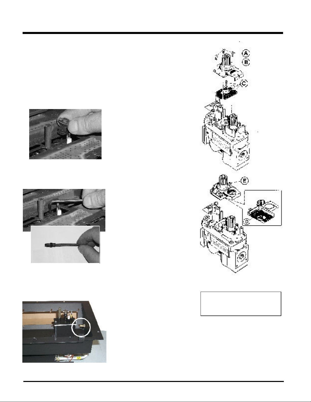
INSTALLATION
4) Remove and discard the 3 pressure regulator mounting screws (A), pressure regulator tower (B) and diaphragm (C).
5) Insure that the rubber gasket (D) is properly
positioned and install the new HI/LO pressure regulator assembly to the valve using
the new screws (E) supplied with the kit.
Tighten screws securely.
6) Pull off the pilot cap to expose the pilot
orifice.
7) Unscrew the pilot orifice with the allen key
and replace with the LP pilot orifice in the
kit.
9) Reinstall new burner orifice LP stamped
#51 and tighten.
10)Reverse steps 3) to 2).
11)Attach the Conversion label "This unit has
been converted to Propane" on top of the
Serial # decal.
12)Replace yellow "Natural Gas" label with red
"Propane" label
13)Check for gas leaks.
14)Check inlet and outlet pressures.
15)Check operation of flame control.
16)Check for proper flame appearance and
glow on logs.
8) Remove burner orifice with a 1/2" wrench
and discard. Use a wrench to hold on to the
elbow behind the orifice.
Installer Notice:
These instructions must be left
with the appliance.
Burner Orifice
26 Hampton H35 Direct Vent Freestanding Gas Stove
Page 27
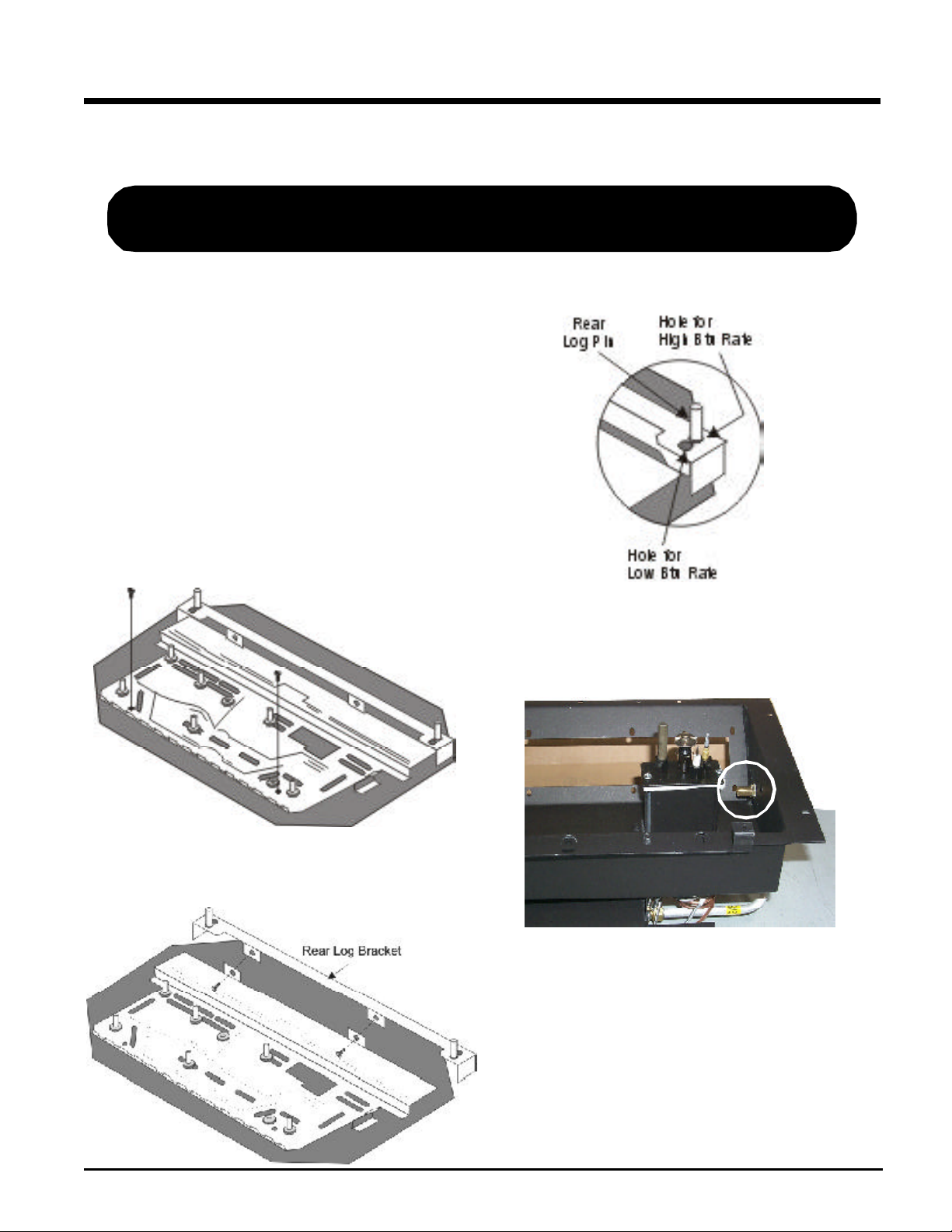
INSTALLATION
Conversion Kit to Lower Btu Rating for H35 Hampton
Natural Gas - Kit #: 740-950 Propane - Kit # 740-952
THIS CONVERSION MUST BE DONE BY A QUALIFIED GAS FITTER
IF IN DOUBT DO NOT DO THIS CONVERSION !!
Natural Gas Conversion Kit 740-950 Contains:
Qty. Part # Description
1 904-240 Burner Orifice #37 (Natural Gas)
1 918-034 Decal "Converted to 30,000 Btu"
1 918-148 Instruction Sheet
Propane Conversion Kit 740-952 Contains:
Qty. Part # Description
1 904-390 Burner Orifice #52 (Propane)
1 918-149 Decal "Converted to 28,500 Btu"
1 918-148 Instruction Sheet
1) Shut off the gas supply.
2) Open the front door. Carefully remove the logs and lava rock. (Refer
to manual for more detailed instructions.)
3) Remove burner by removing 2 screws, sliding the burner to the left
and lift out. See diagram below.
5) Unscrew the 2 Rear Log Pins and move to the front hole position.
6) Reinstall Rear Log Bracket.
7) Remove burner orifice with a 1/2" wrench and discard.
Note: Use a magnetic type screwdriver if possible.
4) Remove Rear Log Bracket by removing 2 screws. See diagram
below.
Hampton H35 Direct Vent Freestanding Gas Stove
Burner Orifice
8) Reinstall new burner orifice (NG stamped #37 or LP stamped #52)
and tighten.
9) Reverse steps 3) and 2).
27
Page 28
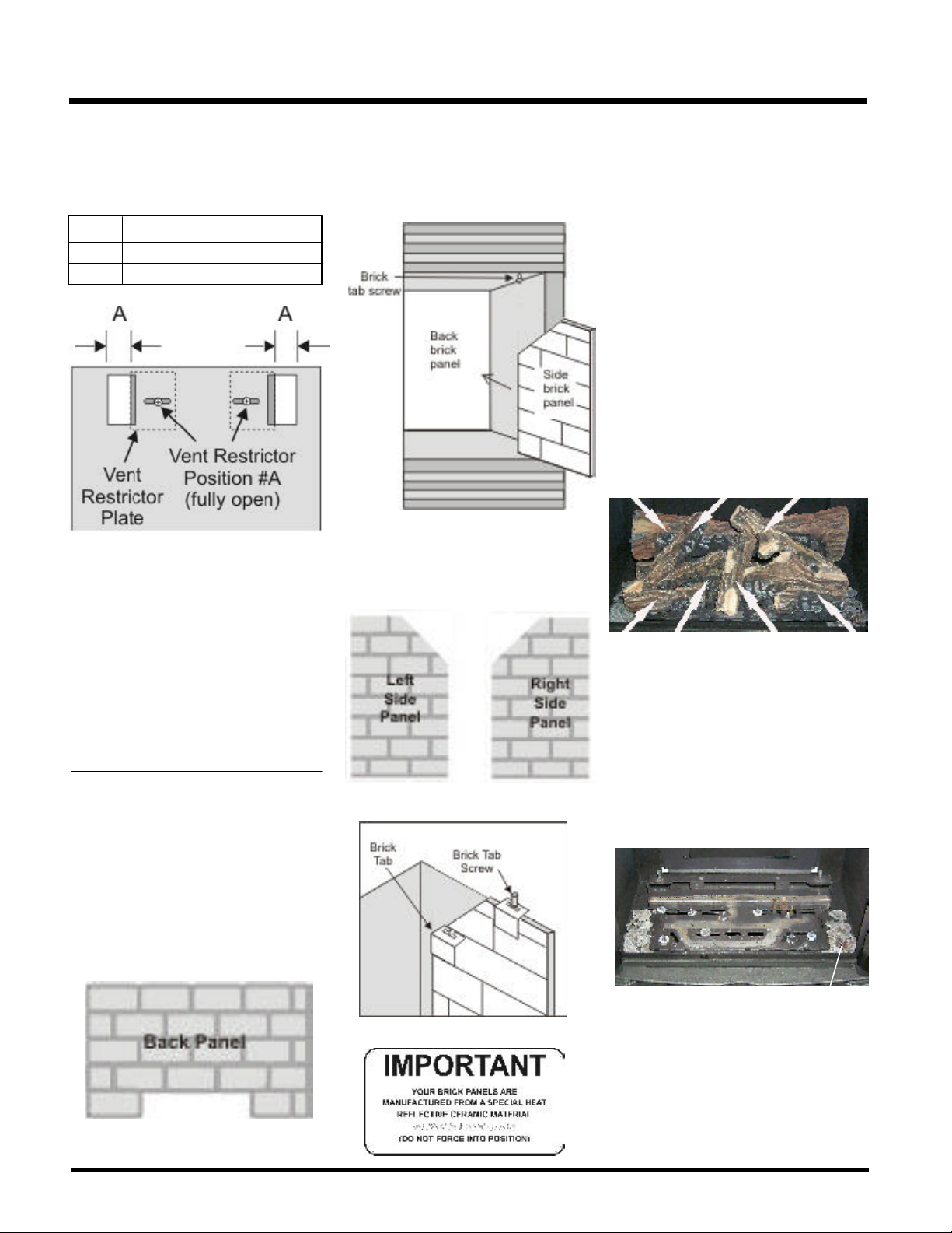
INSTALLATION
10)Adjust Vent restrictor setting: To set the
Vent restriction as indicated in the diagram,
simply loosen the screws and push the
vent restrictor plate to the correct position.
Tighten the screws.
Unit Btu/h Restrictor Opening
H35 NG 30,000 A 1-3/4" (45mm)
H35 LP 28,500 A 1-3/4" (45mm)
Vent Restrictor setting at
Low Btu for Straight
Horizontal Venting
11)Attach the label "This unit has been con-
verted to..." on top of the Serial # decal over
the higher Btu information.
12)Check for gas leaks.
13)Check inlet and outlet pressures.
14)Check operation of flame control. Check for
proper flame appearance and glow on logs.
4) Before installing the side brick panels, loosen the screws for the brick tabs enough so
that you can slide the brick tabs on to the
screws easily but that the tabs are secure.
For the location of the side brick tab screws
see diagram 1.
Diagram 1
5) Put the side panels in next. Slide them in
from the front and push them flat up against
the wall. Be very careful not to scratch
them on the firebox hardware.
LOG SET
INSTALLATION
Read the instructions below carefully and
refer to the diagrams. If logs are broken
do not use the unit until they are replaced.
Broken logs can interfere with the pilot
operation.
The gas log kit contains the following:
a) 02-43 Rear Log
b) 02-56 Middle Left Log
c) 02-44 Front Left Log
d) 02-46 Left Top Log
e) 02-45 Front Right Log
f) 02-47 Center Log
g) 02-48 Middle Right Log
h) Embers
i) Lava
A) 02-43 D) 02-46
C) 02-44 B) 02-56 F) 02-47
The "02" refer numbers (i.e. 02-43) are
molded into the rear of each log.
1) Carefully remove the logs from the box and
unwrap them. The logs are fragile, handle
with care - do not force into position.
G) 02-48
E) 02-45
2) Lift off the Cast Top and remove the glass
GAS FIREPLACE
6) Install the brick tabs. See diagram 2.
OPTIONAL BRICK PANEL
1) Remove the cast top and glass front (see
manual for instructions).
2) Remove the log set if installed.
3) Insert the back brick panel first by carefully
slipping it between the back wall of the
firebox and the rear log bracket.
Diagram 2
28 Hampton H35 Direct Vent Freestanding Gas Stove
front (see page 36).
3) Sprinkle the embers on the left and right
sides of the firebox base.
Embers Embers
Page 29
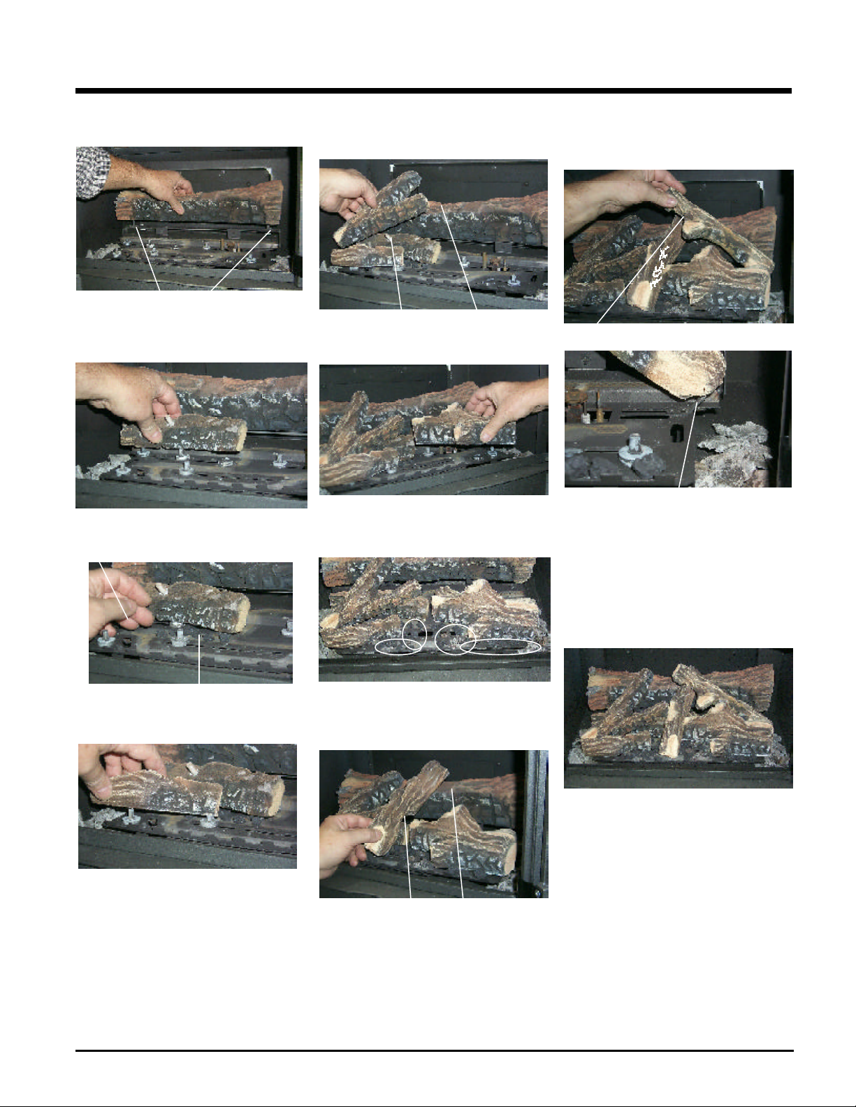
INSTALLATION
3) Place Rear Log A)02-43 on the two pins on
the rear log support.
A)02-43
Pins on Rear Log Support
4) Place the Middle Left Log B)02-56 on the
two pins as shown.
B)02-56
5) Sprinkle some lava rock just in front of B)
02-56 on the burner holes.
7) Place the Left Top Log D)02-46 on the pin
on Log B)02-56 and on top of the cutout on
Log A)02-43.
D)02-46
C)02-44
8) Place Front Right Log E)02-45 on the two
pins as shown.
9) Place the lava rock in the area between the
left and right logs, leaving a space in the
middle for log (F) 02-47.
B)02-56
Pin
E)02-45
A)02-43
Cutout
11)Position notch in Front Right Log G)02-48 on
Log F)02-47 and push the bottom right edge
against the bracket on the burner tray.
A)02-43
G)02-48
E)02-45
Notch
G)02-48
Side View
Bracket
The bottom right edge of Log G)02-48 must
sit snugly against the bracket. (Front Log
02-45 has been removed so that the
bracket can be seen.)
B)02-56
lava rock
6) Place Front Left Log C)02-44 onto the 2
front pins as shown.
C)02-44
10)Place the notch in Center Log F)02-47 over
Log E)02-45 and across the cutout on Log
A)02-43.
F)02-47
Notch
A)02-43
E)02-45
Cutout
12)Test fire to ensure proper light off (make
sure flame flows smoothly from one end of
burner to the other. If there is any flame
hesitation, check that area for any blockage of the burner port.
G)02-48
A)02-43
D)02-46
B)02-56
C)02-44
F)02-47
E)02-45
Hampton H35 Direct Vent Freestanding Gas Stove
29
Page 30
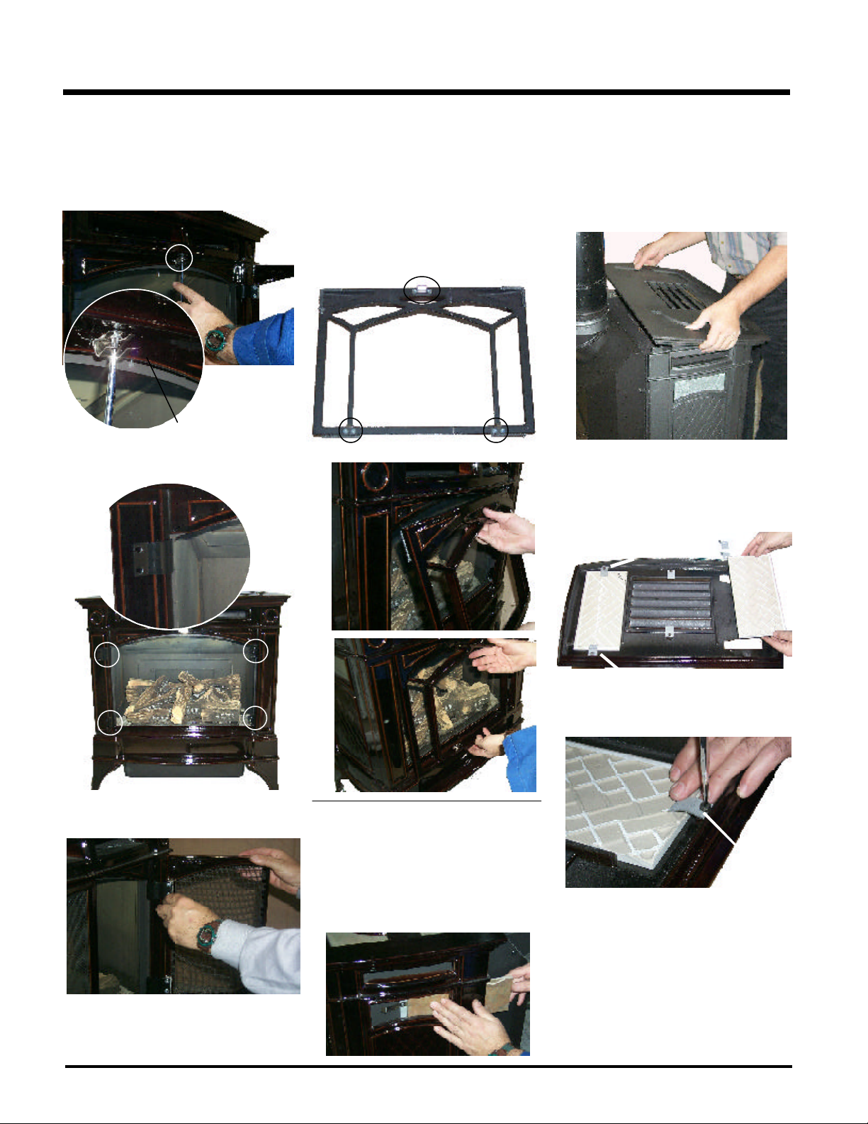
INSTALLATION
OPTIONAL DOUBLE
DOOR INSTALLATION
1) Secure the Top Door Clip into the Top Front
Casting.
Top Door Clip
2) Pull all four door hinges out from the sides
of the Front Casting.
DECORATIVE DOOR
GRILL INSTALLATION
1) Hook the Top Clip on the Decorative Door
Grill into the top lip of the Front Casting.
2) Lift the Decorative Door Grill slightly and
drop the Bottom Clips into the bottom lip of
the Front Casting.
Top Clip
Rear View of
Decorative Door Grill
Bottom Clip
Bottom Clip
2) Slide the Optional Side Tile Inset into the
side panel, over the spring clip.
3) Repeat for other side.
Top Tile Inset
1) Lift the Cast Top off the unit.
2) Place the Cast Top face down on a soft
surface. Take care not to scratch the finish
on the Top.
3) Remove the Tile Clips holding the Standard
Tile Insets in place.
3) Fasten the Right Door to the 2 right hinges
(2 screws per hinge).
TILE INSET
INSTALLATION
Side Tile Inset
1) Slide the Standard Side Tile Inset out towards the back of the unit.
Tile Clip
Tile Clip
4) Place the Optional Tile Insets into position
and secure with a top and bottom Tile Clip.
Tile Clip
5) Replace the Cast Top on the unit.
Repeat for the Left Door.
30 Hampton H35 Direct Vent Freestanding Gas Stove
Page 31
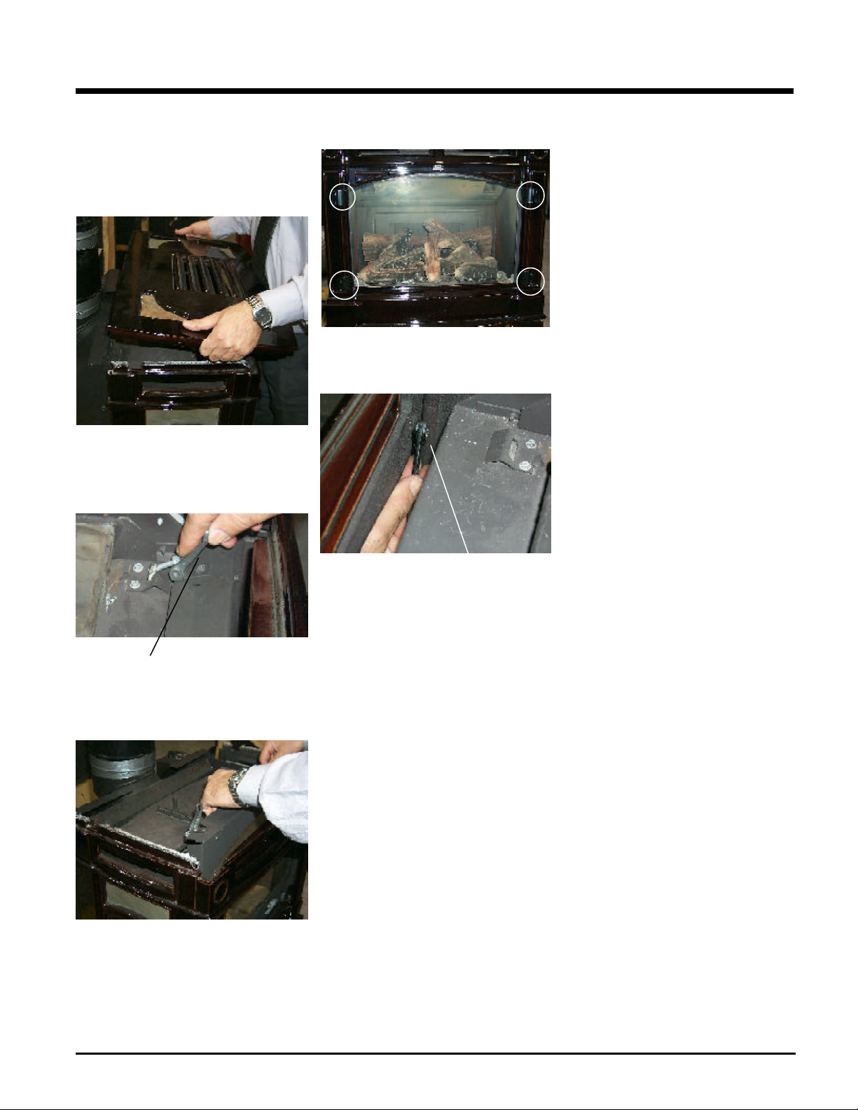
INSTALLATION
DOOR HINGE
REMOVAL
1) Remove the cast top by lifting it off of the
stove.
2) Release the catches on the left and right
side of the stove that secure the glass.
4) Pull all four door hinges out from the sides
of the front casting.
5) Use a 7/16" wrench to remove the screws
that secure the door hinges.
Release catch by
pulling up.
3) Remove the glass by sliding it up and out.
Remove screws.
Hampton H35 Direct Vent Freestanding Gas Stove
31
Page 32
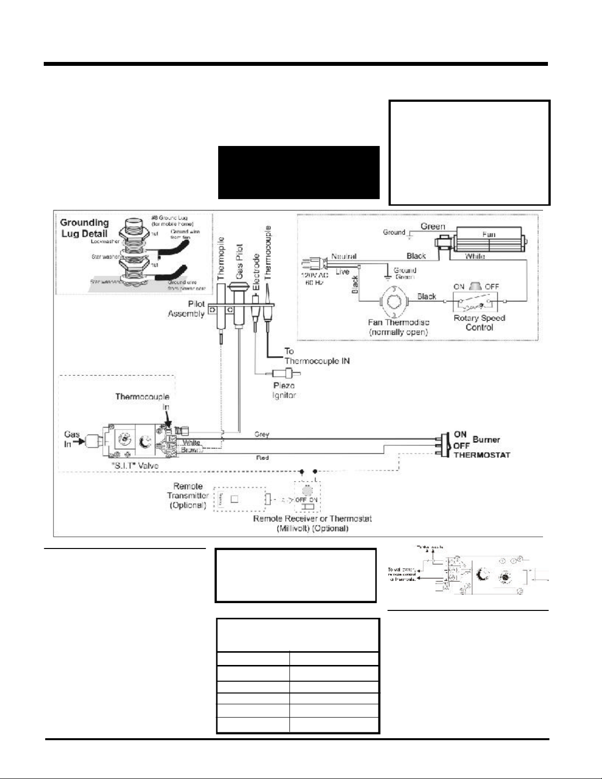
INSTALLATION
WIRING DIAGRAM - H35-NG & H35-LP
If any of the original wires as supplied with the
appliance must be replaced, it must be replaced
with CSA type SEW (200oC) or its equivalent.
This heater does not require a 120V A.C. supply
for operation. In case of a power failure, the
burner switch and the optional remote control/
thermostat will continue to operate. However,
a 120V A.C. power supply is needed for the
fan/blower operation.
Caution: Ensure that the wires do
not touch any hot surfaces and are
away from sharp edges.
CAUTION: Label all wires prior to
disconnection when servicing controls. Wiring errors can cause improper and dangerous operation.
WARNING: Electrical Grounding
Instructions
This appliance is equipped with a
three pronged (grounding) plug for
your protection against shock hazard and should be plugged directly
into a properly grounded three-prong
receptacle. Do not cut or remove the
grounding prong from this plug.
OPTIONAL WALL
CAUTION
Do not connect the millivolt
THERMOSTAT
wall thermostat wires
to the 120V wires.
A wall thermostat may be installed if desired.
Connect the wires as per the wiring diagrams.
Note that the wires are connected to the "TH"
on the gas valve. Use table below to determine
the maximum wire length:
Note: Preferable if the thermostat is installed on an interior wall.
Hampton offers an optional programmable thermostat but any 250-750 millivolt rated nonanticipator type thermostat that is CSA, ULC or
UL approved may be used.
32 Hampton H35 Direct Vent Freestanding Gas Stove
Thermostat Wire Table
Recommended Maximum Lead Length
(Two-Wire) When Using Wall
Thermostat (CP-2 System)
Wire Size Max. Length
14 GA.
16 GA.
18 GA.
20 GA.
22 GA.
50 Ft.
32 Ft.
20 Ft.
12 Ft.
9 Ft.
OPTIONAL REMOTE
CONTROL
Use the Hampton Remote Control Kit approved
for this unit. Use of other systems may void your
warranty.
The remote control kit comes with a hand held
transmitter, a receiver and a wall mounting
plate.
Page 33
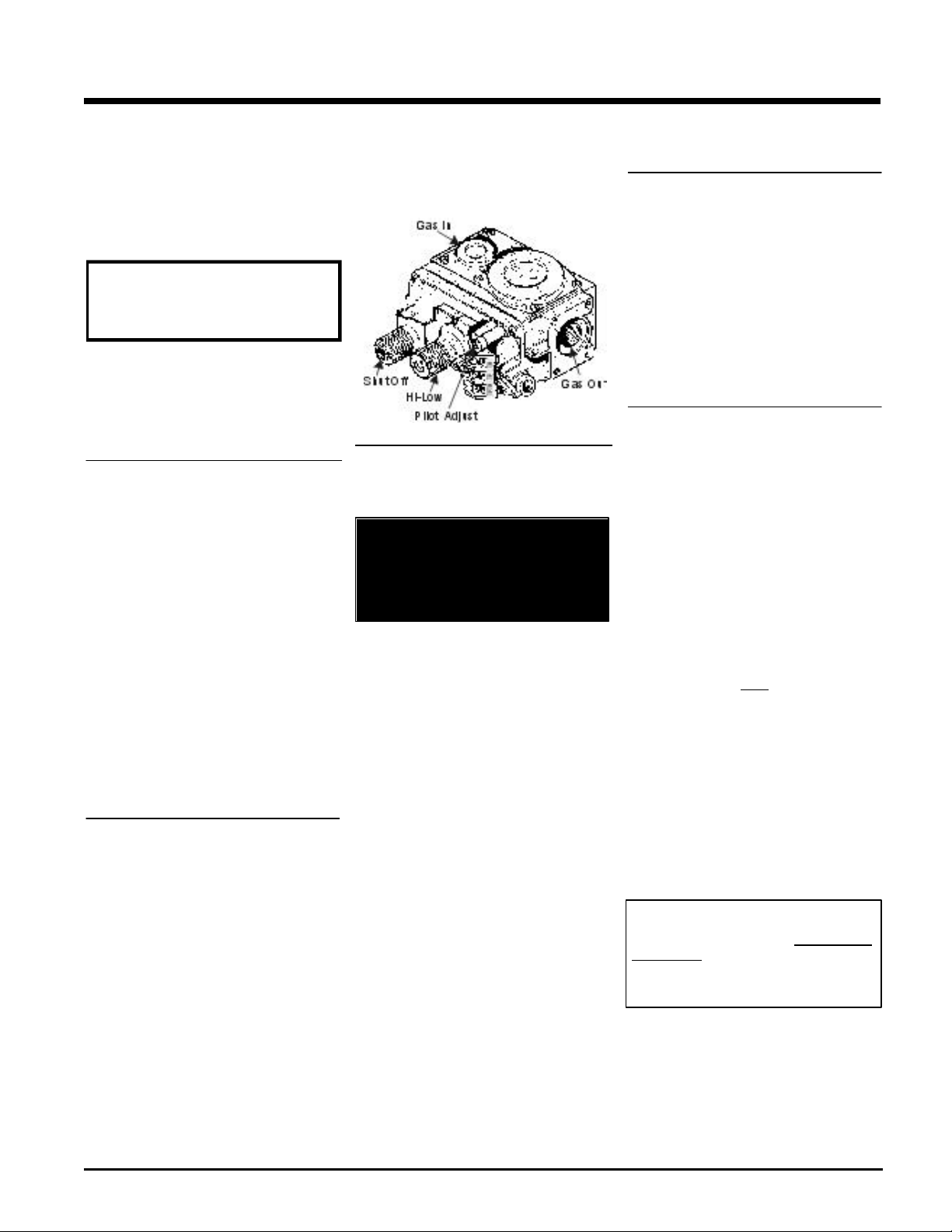
OPERATING INSTRUCTIONS
1) Choose a convenient location on the wall to
install the receiver and the receptacle box
(protection from extreme heat is very important). Run wires from the fireplace to that
location, use Thermostat Wire Table.
2) Connect the wires as per the wiring diagram
below.
CAUTION
Do not connect the
millivolt remote control wires
to the 120V wires.
3) Install 3 AAA alkaline batteries in transmitter
and 4 AA alkaline batteries in the receiver.
Install the receiver and its cover in the wall.
Switch the remote receiver to "remote"
mode. The remote control is now ready for
operation.
FINAL CHECK
Before leaving this unit with the customer, the
installer must ensure that the appliance is firing
correctly. This includes:
1) Clocking the appliance to ensure the correct
firing rate (rate noted on label) at 15 minutes.
2) If required, adjusting the primary air to ensure that the flame does not carbon. First
allow the unit to burn for 15 min. to stabilize.
3) Check for proper draft.
CAUTION
Any alteration to the product that causes
sooting or carboning that results in damage to the exterior facia is not the responsibility of the manufacturer.
OPERA TING
INSTRUCTIONS
1) Read and understand these instructions
before operating this appliance.
2) Check to see that all wiring is correct and
enclosed to prevent possible shock.
3) Check to ensure there are no gas leaks.
4) Make sure the glass in the door frame is
properly positioned. Never operate the
appliance with the glass removed. Never
strike the glass or slam the door shut.
5) Verify that the venting and cap are unobstructed.
6) Verify log placement. If the pilot cannot be
seen when lighting the unit - the logs have
been incorrectly positioned.
7) The unit should never be turned off, and on
again without a minimum of a 60 second
wait.
LIGHTING
PROCEDURE
IMPORTANT
To ignite or reignite the pilot,
the door to the firebox must
be opened.
Only when the pilot holds, without pressure
being applied to the control knob, should the
door to the firebox be closed. The unit must
never be operated with the glass or door
open.
IMPORTANT: Gas cock knob cannot be
turned from "PILOT" to "OFF" unless it is
partially depressed.
1) Turn stove OFF using the Burner "ON/OFF"
switch remote or thermostat.
2) Turn gas control knob so indicator points to
"OFF" position and allow 5 minutes for any
gas in the combustion chamber to escape.
3) Turn gas control knob counterclockwise so
indicator points to the "PILOT" position. Depress the gas control knob fully. Depress
the igniter button several times until the pilot
lights. After approximately one minute, release the gas control knob. The pilot flame
should continue to burn. If the pilot does not
remain lit, repeat operation allowing a longer
period before releasing gas control knob.
4) When the pilot stays lit, turn the gas knob
further counterclockwise to the "ON" position.
5) Use the thermostat or remote control to turn
on the unit.
6) Rotate the flame height regulator to adjust
the flame height higher or lower.
SHUTDOWN
PROCEDURE
1) Use the thermostat or remote control to turn
off the main burner.
2) Turn the main gas control clockwise to the
"OFF" position to turn off the pilot (push
knob in slightly).
3) Turn off all electric power to appliance if
service is to be performed.
FIRST FIRE
The FIRST FIRE in your stove is part of the paint
curing process. To ensure that the paint is
properly cured, it is recommended that you burn
your fireplace for at least four (4) hours the first
time you use it with the fan on. When first
operated, the unit will release an odour caused
by the curing of the paint and the burning off of
any oils remaining from manufacturing. Smoke
detectors in the house may go off at this time.
Open a few windows to ventilate the room for
a couple of hours. The glass may require
cleaning.
DO NOT ATTEMPT TO CLEAN THE GLASS
WHILE IT IS STILL HOT!
Note: When the glass is cold and the
appliance is lit, it may cause condensation and fog the glass. This
condensation is normal and will
disappear in a few minutes as the
glass heats up.
DO NOT BURN THE APPLIANCE
WITHOUT THE GLASS FRONT IN
PLACE.
During the first few fires, a white film
may develop on the glass front as part
of the curing process. The glass should
be cleaned or the film will bake on and
become very difficult to remove. Use a
non-abrasive cleaner and NEVER clean
the glass while it is hot.
Hampton H35 Direct Vent Freestanding Gas Stove
33
Page 34
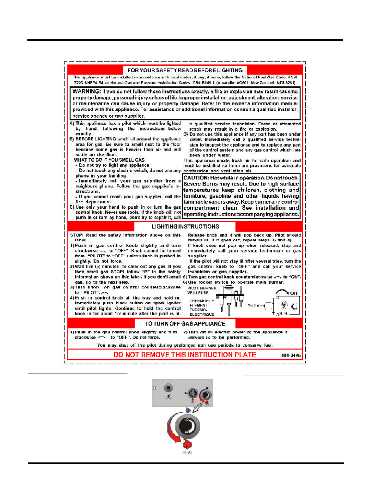
OPERATING INSTRUCTIONS
Copy of the Lighting Plate instructions
ADJUSTING FLAME
HEIGHT
Your heater has an adjustable flame to tailor the
look and heat output to your specific needs. It
is adjusted by turning the flame adjustment dial
on the gas control valve.
Turn clockwise to adjust the flame higher,
counterclockwise for a lower flame.
34 Hampton H35 Direct Vent Freestanding Gas Stove
AUTOMATIC CONVEC-
TION FAN OPERA TION
The fan operates automatically - turn the knob
at the top right rear corner to adjust to the
desired speed. The fan will turn on as the stove
comes up to operating temperature. After the
unit has been turned off and the unit cooled to
below a useful heat output range the fan will
shut off automatically.
Page 35
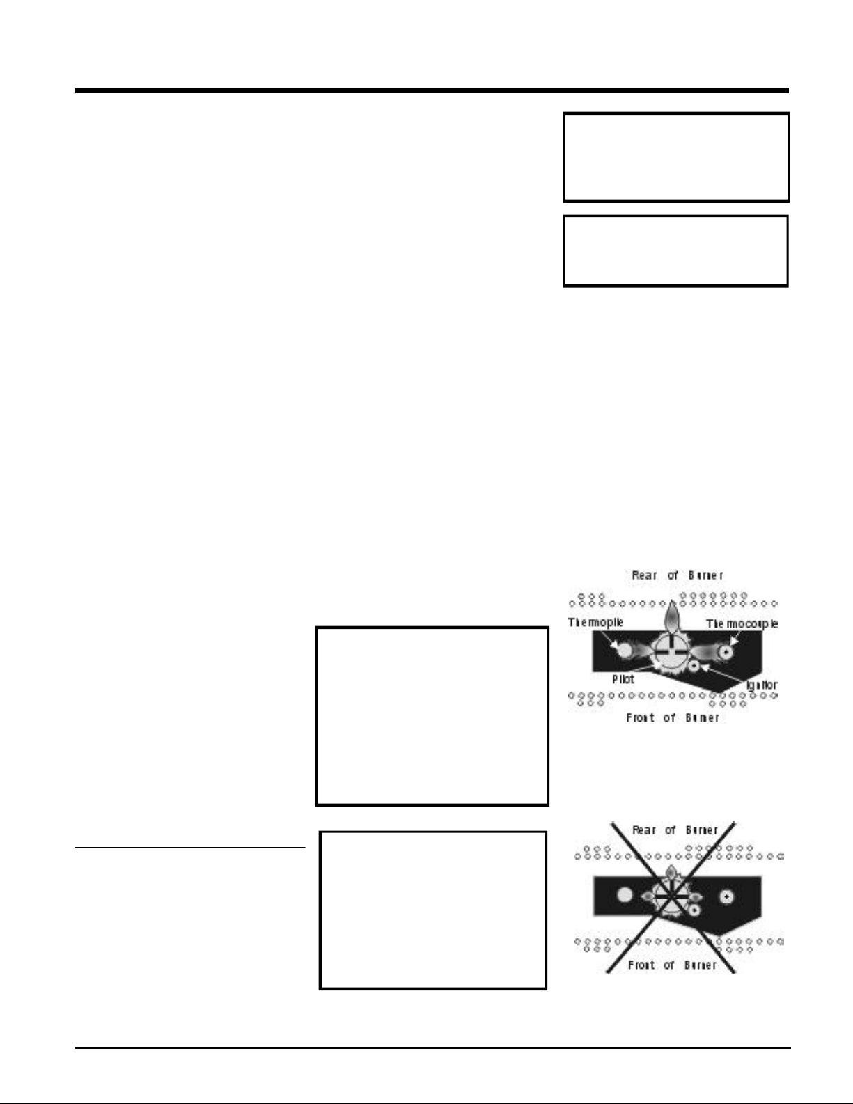
MAINTENANCE
NORMAL OPERA TING
SOUNDS OF
GAS APPLIANCES
It is possible that you will hear some sounds
from your gas appliance. This is perfectly normal due to the fact that there are various gauges
and types of steel used within your appliance.
Listed below are some examples. All are nor-
mal operating sounds and should not be
considered as defects in your appliance.
Blower:
Hampton gas appliances use high tech blowers
to push heated air farther into the room. It is not
unusual for the fan to make a "whirring" sound
when ON. This sound will increase or decrease
in volume depending on the speed setting of
your fan speed control.
Burner Tray:
The burner tray is positioned directly under the
burner tube(s) and logs and is made of a
different gauge material from the rest of the
firebox and body. Therefore, the varying thicknesses of steel will expand and contract at
slightly different rates which can cause "ticking" and "cracking" sounds. You should also be
aware that as there are temperature changes
within the unit these sounds will likely re-occur.
Again, this is normal for steel fireboxes.
Blower Thermodisc:
When this thermally activated switch turns ON
it will create a small "clicking" sound. This is the
switch contacts closing and is normal.
Pilot Flame:
While the pilot flame is on it can make a very slight
"whisper" sound.
Gas Control Valve:
As the gas control valve turns ON and OFF, a
dull clicking sound may be audible, this is normal
operation of a gas regulator or valve.
Unit Body/Firebox:
Different types and thicknesses of steel will
expand and contract at different rates resulting
in some "cracking" and "ticking" sounds will be
heard throughout the cycling process.
2) Clean glass (never when unit is hot), appliance, and door with a damp cloth. Never
use an abrasive cleaner.
3) The heater is finished in a porcelain finish
or with a heat resistant paint and should
only be refinished with heat resistant paint
(not with wall paint).
Never use an abrasive cleaner on the
porcelain finish as it may scratch the surface.
4) Make a periodic check of burner for proper
position and condition. Visually check the
flame of the burner periodically, making
sure the flames are steady; not lifting or
floating. If there is a problem, call a qualified
service person.
5) Caution: Label all wires prior to disconnection when servicing controls. Wiring errors
can cause improper and dangerous operation.
6) The appliance and venting system must be
inspected before use, and at least annually, by a qualified field service person, to
ensure that the flow of combustion and
ventilation air is not obstructed.
During the annual service call, the burners
should be removed from the burner tray
and cleaned. Replace the embers but do not
block the pilot.
7) Keep the area near the appliance clear and
free from combustible materials, gasoline,
and other flammable vapours and liquids.
WARNING: CHILDREN AND ADULTS
SHOULD BE ALERTED TO THE
HAZARDS OF HIGH SURFACE
TEMPERATURE AND SHOULD
STAY AWAY TO AVOID BURNS
OR CLOTHING IGNITION. YOUNG
CHILDREN SHOULD BE CAREFULLY SUPERVISED WHEN THEY
ARE IN THE SAME ROOM AS THE
APPLIANCE.
CAUTION: ANY SAFETY SCREEN
OR GUARD REMOVED FOR SERVICING AN APPLIANCE MUST BE
REPLACED PRIOR TO OPERATING THE APPLIANCE.
CLOTHING OR OTHER FLAMMABLE MATERIAL SHOULD NOT BE
PLACED ON OR NEAR THE APPLIANCE.
8) Each time the appliance is lit, it may cause
condensation and fog the glass. This condensation and fog is normal and will disappear in a few minutes as the glass heats up.
Never operate the appliance without
the glass properly secured in place.
9) Periodically check the pilot flames. Correct
flame pattern has three strong blue flames:
1 flowing around the thermopile and 1
around the thermocouple, and 1 flowing
across the rear of the burner (it does not
have to be touching the burner).
Note: If you have an incorrect flame pat-
tern, contact your Hampton dealer
for further instructions.
Top View of pilot flame
Incorrect flame pattern will have small, probably
yellow flames, not coming into proper contact
with the rear of the burner or thermopile.
MAINTENANCE
INSTRUCTIONS
1) Always turn off the valve before cleaning.
For relighting, refer to lighting instructions.
Keep the burner and control compartment
clean by brushing and vacuuming at least
once a year. When cleaning the logs, use a
soft clean paint brush as the logs are fragile
and easily damaged.
Hampton H35 Direct Vent Freestanding Gas Stove
DO NOT USE THIS APPLIANCE IF
ANY PART HAS BEEN UNDER WATER. IMMEDIATELY CALL A
QUALIFIED SERVICE TECHNICIAN TO INSPECT THE APPLIANCE AND TO REPLACE ANY
PART OF CONTROL SYSTEM
AND ANY GAS CONTROL WHICH
HAS BEEN UNDER WATER.
Top View of pilot flame
35
Page 36
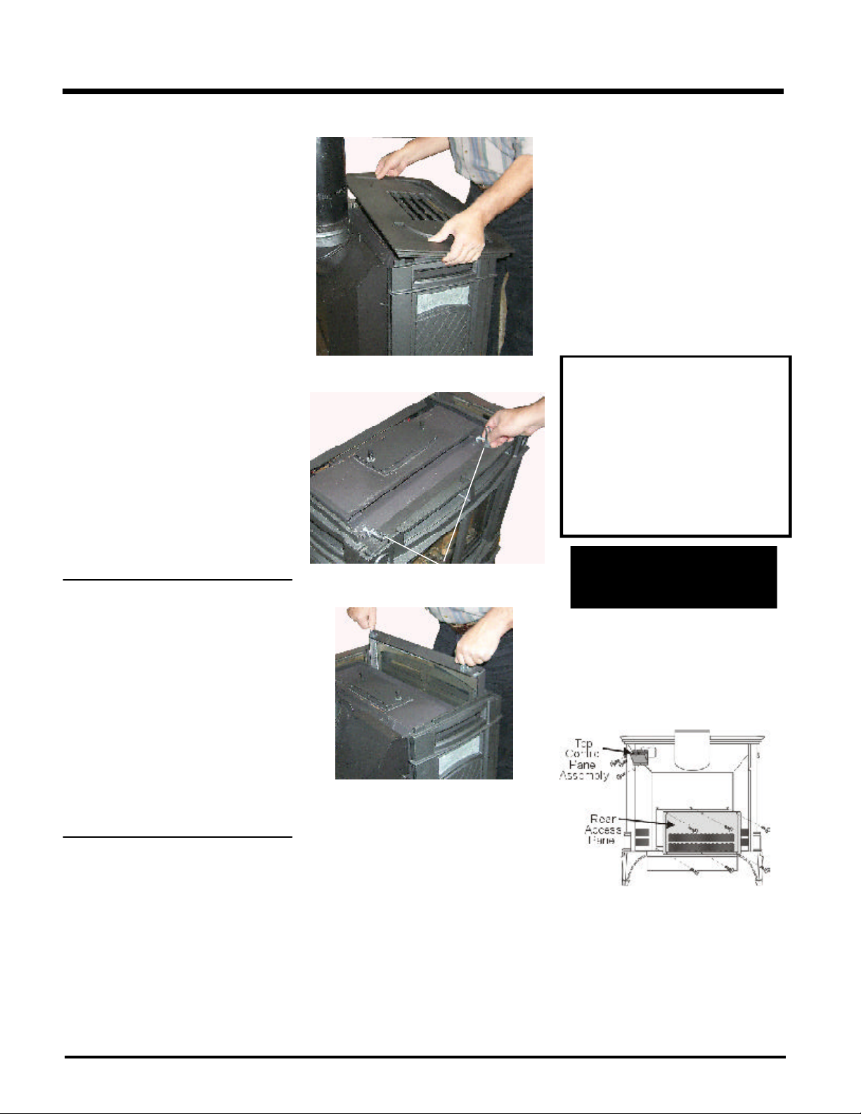
MAINTENANCE
GENERAL VENT
MAINTENANCE
Conduct an inspection of the venting system
semi-annually. Recommended areas to inspect
as follows:
1) Check the Venting System for corrosion in
areas that are exposed to the elements.
These will appear as rust spots or streaks,
and in extreme cases, holes. These components should be replaced immediately.
2) Remove the Cap, and shine a flashlight
down the Vent. Remove any bird nests, or
other foreign material.
3) Check for evidences of excessive condensation, such as water droplets forming in
the inner liner, and subsequently dripping
out the joints, Continuous condensation
can cause corrosion of caps, pipe, and
fittings. It may be caused by having excessive lateral runs, too many elbows, and
exterior portions of the system being exposed to cold weather.
4) Inspect joints, to verify that no pipe sections
or fittings have been disturbed, and consequently loosened. Also check mechanical
supports such as Wall Straps, or plumbers'
tape for rigidity.
LOG REPLACEMENT
1) Lift off the Cast Top.
2) Open the 2 latches of the Glass Front.
Latches
3) Lift the Glass Front Assembly up.
FAN MAINTENANCE
If your fan requires maintenance or replacement, access to the fan is through the rear
access panel on the back of the unit. NOTE: the
unit MUST NOT be operated without the
fan access panel securely in place and
correctly sealed.
IMPORTANT: These fans collect a lot of
dust from within your home. Ensure you
maintain these fan motors on a regular
basis by vacuuming out the fan squirrel
cages, around the motor, and around the
grills on the back of the stove.
WARNING:
Electrical Grounding Instructions
This appliance is equipped with a
three pronged (grounding) plug
for your protection against shock
hazard and should be plugged
directly into a properly grounded
three-prong receptacle. Do not cut
or remove the grounding prong
from this plug.
IMPORTANT
Disconnect power supply
before servicing
The unit should never be used with broken logs.
Turn off the gas valve and allow the unit to cool
before opening door to carefully remove the
logs. The pilot light generates enough heat to
burn someone. If for any reason a log should
need replacement, you must use the proper
replacement log. The position of these logs
must be as shown in the diagram under Log
Installation.
Note: Improper positioning of logs may
create carbon build-up and will
alter the unit’s performance which
is not covered under warranty.
GLASS
REPLACEMENT
Your stove is supplied with high temperature,
5 mm Neoceram ceramic glass that will withstand the highest heat that your unit will produce. In the event that you break your glass by
impact, purchase your replacement door from
an authorized Hampton dealer only, and follow
our step-by-step instructions for replacement.
4) Remove the glass and replace with the
new glass.
5) Replace the door and Cast Top.
Replacement Part # 940-324 Glass
WARNING: Do not operate appliance with glass panel removed,
cracked or broken. Replacement of
the glass should be done by a licensed or qualified service person.
Note: Wearing gloves will protect your
hands while handling glass.
To remove fan:
1) Unplug or disconnect power source to
stove.
2) Remove the 6 screws holding the access
panel in place.
3) Unclip the black and white wires from the
fan motor.
4) Lift fan off of the 2 pins, tip back and pull
through rear panel. Do not tear or damage
the flex pipe when removing the fan. Disconnect the green ground wire from the
right side of the fan as soon as you can
reach it.
36 Hampton H35 Direct Vent Freestanding Gas Stove
Page 37
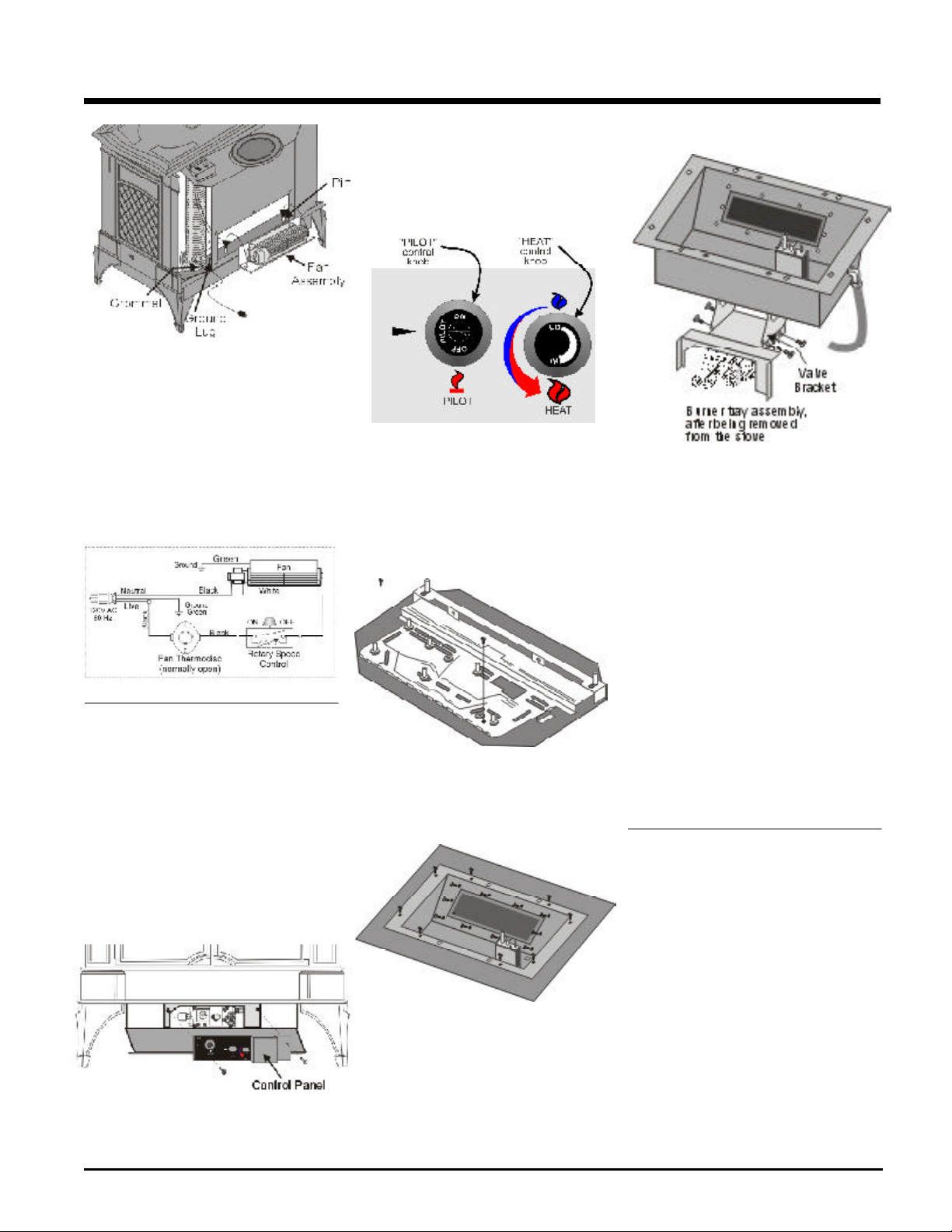
MAINTENANCE
Replacing the Fan:
Reverse the above steps (1 - 4). Make sure the
fan wires and the ground wire are reattached.
Hint for pushing fan down onto pins - rub a bit
of dish soap on the grommet so it will slide more
easily onto the pin. Check to make sure the fan
is seated properly on the pins - try to move the
fan back and forth, there should be no noise,
if there is check that the grommets haven't
come loose.
3) Disconnect gas line to stove.
4) Disconnect 3/8" NPT pipe from 90o elbow on
valve.
5) Disconnect the two (2) switch wires from
valve.
6) Disconnect piezo wire.
7) Lift off the Cast Top and lift out the front
door.
8) Carefully remove the logs, embers and
rockwool.
9) Remove burner. See diagram below.
11)Carefully lift the burner tray assembly out.
12)To replace the burner tray assembly, simply
reverse these instructions.
To remove valve from valve assembly,
continue.
13)Remove two (2) thermopile wires.
14)Remove thermocouple with a 9 mm (metric)
wrench.
REMOVING VALVE
If your valve requires maintenance or replacement, use the following instructions:
Note: Always close off the gas supply
before removing the valve.
1) If optional fan is installed, disconnect pow-
er source to stove.
2) Remove access panel.
Note: Use a
magnetic type
screwdriver if possible.
10)Remove all 18 screws holding the burner
tray assembly in place.
15)Remove pilot nut with an 11 mm wrench.
16)Remove valve to orifice nut with a 13/16"
wrench.
17)Remove inlet pipe with pipe wrench. Note
orientation of 90o elbow.
18)Remove two (2) phillips head M5 screws on
each side of the valve.
19)Remove valve and remove gas out 90
brass fitting. Note orientation of fitting.
INSTALLING VALVE
ASSEMBLY
1) To install a new valve assembly, reverse
instructions for removing valve. See
assembly steps 1-12.
2) Check for leaks and manifold pressure. See
Gas Pressure Test instructions.
3) To reinstall valve, reverse instructions for
removing valve assembly, steps 13-19.
o
Hampton H35 Direct Vent Freestanding Gas Stove
37
Page 38
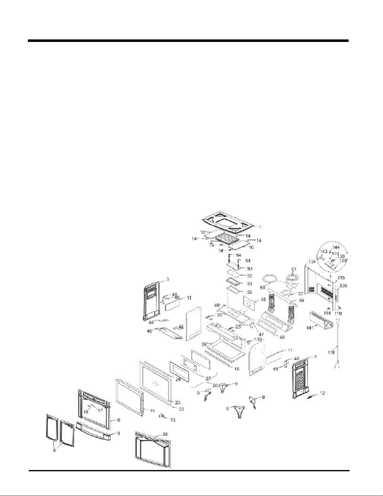
PARTS LIST
MAIN ASSEMBLY
Part # Description Part # Description Part # Description
1) 942-301** Casting - Top
2) 942-311** Casting - Top Grill
3) 942-321** Casting - Left Side
4) 942-331** Casting - Right Side
5) 942-341** Casting - Front
6) 740-931** Casting - Double Door
8) 942-371** Casting - Bottom Skirt
9) 942-381** Casting - Leg
10) 942-391** Casting - Insert Plate - Top
11) 942-401** Casting - Insert Plate - Side
12) 948-219 Hampton Logo Plate
14) 740-062 Top Insert Bracket
15) 904-209 Concealed Hinge
16) 740-069 Cast Door Catch - Top
17) 740-067 Cast Door Catch - Lower
740-542 Front Door Assembly
18) 740-051 Door Support
19) 740-055 Door Frame
22) 41225 Gasket - Tadpole
23) 940-324/P Replacement Glass
24) 740-056 Glass Bracket
25) 948-255 Latch
56) W842051 Gasket - Upper Air
Passage
Passage Top
57) W260108 Gasket - Upper Air
Passage Bottom
58) 630-009 Gasket - Lower Air
Passage
59) * Upper Air Passage Assy
61) 945F Direct Vent Adaptor
Rear Panel Assembly
114) * Wire Tie Wrap
115) * Wire Tie Mount Button
118) 910-897 High Temperature Wire Harness - Fan End
119) * Grommet for Power Cord
134) 740-049 Rear Panel
135) 260-037 Rear Control Panel
136) 910-241 Burner ON/OFF Switch
137) * Hole Plug 0.375
138) 630-021 Fan Access Panel
139) 910-233 Fan Thermodisc
908-106 Decal-Rear Control Panel
260-917 Fan Assembly (Option)
141) 910-331/P Fan Blower
143) 910-330 Fan Speed Control (120 V)
144) 904-569 Knob - Fan Speed Control
910-794 Power Cord (120 V)
918-085a Manual
*Note: Not available as a replacement part.
**Last digit of part number indicated colour:
1=Charcoal Grey, 2=Slate Blue, 4=Ivory, 5=Timberline Brown.
Auto On/Off
26) 740-548 Relief Door Assembly
27) 740-059 Gasket - Mounting Relief
38) 740-921** Front Grill (Optional)
39) * Firebox
44) 730-029 Restrictor
45) 740-048 Baffle for Firebox
46) * Heat Exchanger Assy
47) * Transition Box Assy
48) 740-061 Side Insert Bracket
49) 740-063 Side Insert Spring
50) W260260 Top Relief Frame Gasket
51) 942-117 Top Relief Frame
52) W260280 Top Relief Plate Gasket
53) 290-021 Top Relief Plate
54) * Capscrew 1/4 x 1-3/4 NC
55) * Gasket - Transition Box/Air
Baffle Restrictor Assembly
Top Relief Door Assembly
38 Hampton H35 Direct Vent Freestanding Gas Stove
Page 39
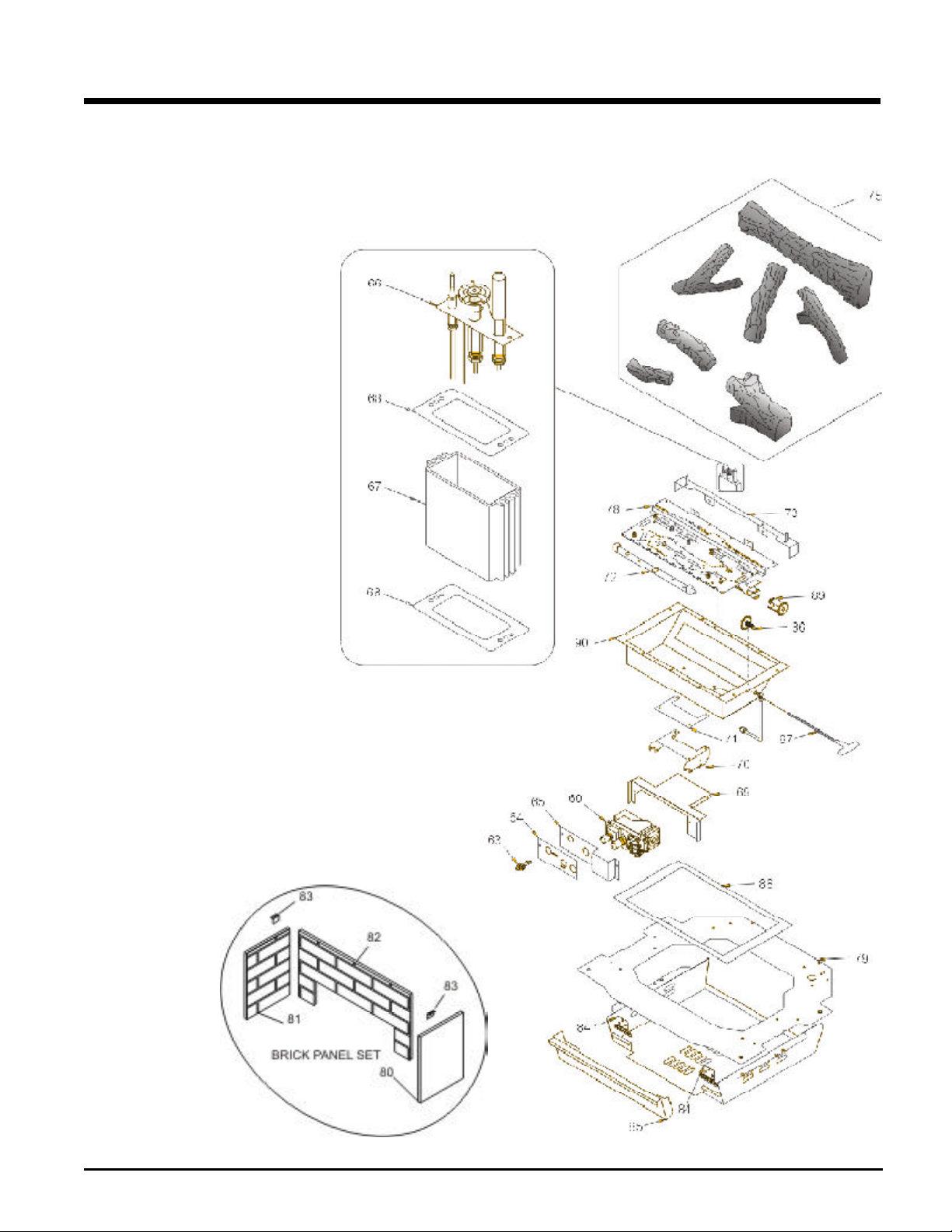
Part # Description
740-574/P Valve Assembly S.I.T. - Natural Gas
740-576/P Valve Assembly S.I.T. - Propane
60) 910-378 Valve S.I.T. - Natural Gas
904-689 #33 Orifice - N.G.
904-645 #51 Orifice - LP
63) 910-190 Piezo Ignitor & Nut
64) 908-672 Control Panel Decal
65) 490-061 Switch Plate
910-897 High Temperature Wire
Harness (Fan End)
936-170 Orifice Gasket
66) 910-038 Pilot Assy-SIT-3 flame-NG
910-039 Pilot Assy-SIT-3 flame-LP
67) 730-041 Pilot Holder
68) W840470 Pilot Assembly Gasket
69) * Valve Shield
70) * Valve Bracket
71) * Valve Gasket
72) * Front Support
73) 730-528 Rear Log Bracket Assy
75) 402-935 Log Set
740-572 Ember Package
78) 730-550 Burner Assy
PARTS LIST
BURNER & LOG ASSEMBLY
740-546 Base Assembly
79) * Base Plate
80) * Brick Panel - Right Side
81) * Brick Panel - Left Side
82) * Brick Panel - Back
83) 400-090 Brick Clip
84) 948-042 Hinge of Valve
85) 260-056 Valve Access Door
86) 260-565 Air Shutter Gear
87) 904-700 T-Handle Hex Key 3/16"
88) 630-008 Burner Tray Firebox Gasket
89) 260-560 Air Shutter Gear Assembly
90) * Burner Box
790-969 Conversion Kit from Natural Gas to Propane
*Note: Not available as a replacement part.
Access Door
Assembly - Female
- Male
Hampton H35 Direct Vent Freestanding Gas Stove
39
Page 40

NOTES
_____________________________________________________________________________________
____________________________________________________________
__________________________________________________________
____________________________________________________________
_______________________________________________________
_____________________________________________________
__________________________________________________________
_________________________________________________________
_________________________________________________________
______________________________________________________
______________________________________________________
_______________________________________________________________
___________________________________________________________
__________________________________________________________
____________________________________________________________
____________________________________________________________
____________________________________________________________
_____________________________________________________________
__________________________________________________________
__________________________________________________________
_____________________________________________________
________________________________________________________
_________________________________________________________
_________________________________________________________
40 Hampton H35 Direct Vent Freestanding Gas Stove
Page 41

NOTES
_____________________________________________________________________________________
____________________________________________________________
__________________________________________________________
____________________________________________________________
_______________________________________________________
_____________________________________________________
__________________________________________________________
_________________________________________________________
_________________________________________________________
______________________________________________________
______________________________________________________
_______________________________________________________________
___________________________________________________________
__________________________________________________________
____________________________________________________________
____________________________________________________________
____________________________________________________________
_____________________________________________________________
__________________________________________________________
__________________________________________________________
_____________________________________________________
________________________________________________________
_________________________________________________________
_________________________________________________________
Hampton H35 Direct Vent Freestanding Gas Stove
41
Page 42

NOTES
_____________________________________________________________________________________
____________________________________________________________
__________________________________________________________
____________________________________________________________
_______________________________________________________
_____________________________________________________
__________________________________________________________
_________________________________________________________
_________________________________________________________
______________________________________________________
______________________________________________________
_______________________________________________________________
___________________________________________________________
__________________________________________________________
____________________________________________________________
____________________________________________________________
____________________________________________________________
_____________________________________________________________
__________________________________________________________
__________________________________________________________
_____________________________________________________
________________________________________________________
_________________________________________________________
_________________________________________________________
42 Hampton H35 Direct Vent Freestanding Gas Stove
Page 43

WARRANTY
Hampton Fireplace Products are designed with reliability and simplicity in mind. In addition, our internal Quality Assurance Team carefully inspects each
unit thoroughly before it leaves our facility. FPI Fireplace Products International Ltd. is pleased to extend this limited lifetime warranty to the original
purchaser of a Waterford Product. This warranty is not transferable.
The Warranty: Limited Lifetime
External casting, not directly in contact with the fire, such as hobs, sides, ash lips, legs, fronts and fire doors, are covered against cracks and warps resulting from
manufacturer defects, parts and subsidized labour* for three (3) years from the date of purchase and parts only thereafter.
The combustion chamber, heat exchanger, burner tubes/pans and logs are covered under the Limited Lifetime Warranty for five (5) years for parts and subsidized labour*
and parts only thereafter.
Glass is covered for lifetime against thermal breakage only, parts and subsidized labour* for five (5) years and parts only thereafter from date of purchase.
Electrical and mechanical components such as blowers, switches, wiring, thermodiscs, FPI remote controls, spill switches, thermopiles, thermocouples, pilot assembly
components, and gas valves are covered for one year parts and subsidized labour* from the date of purchase. Blowers and valves replaced under warranty are considered
repairs and continue as if new with appliance. ie. twelve (12) months from original purchase date of appliance with a minimum of three (3) months coverage from date
of replacement.
FPI venting components are covered parts and subsidized labour* for three (3) years from date of purchase.
Simpson Dura-Vent venting components are covered by Simpson Dura-Vent Inc. warranty.
Conditions:
Porcelain/Enamel - Absolute perfection is neither guaranteed nor commercially possible. Any chips must be reported and inspected by an authorized dealer within three
days of installation. Reported damage after this time will be subject to rejection.
Any part or parts of this unit which in our judgement show evidence of such defects will be repaired or replaced at FPI's option, through an accredited distributor or agent
provided that the defective part be returned to the distributor or agent Transportation Prepaid, if requested.
It is the general practice of FPI to charge for larger, higher priced replacement parts and issue credit once the replaced component has been returned to FPI and evaluated
for manufacturer defect.
The authorized selling dealer is responsible for all in-field service work carried out on your Waterford product. FPI will not be liable for results or costs of workmanship
from unauthorized service persons or dealers.
At all times FPI reserves the right to inspect product in the field which is claimed to be defective.
All claims must be submitted to FPI by authorized selling dealers. It is essential that all submitted claims provide all of the necessary information including customer
name, purchase date, serial #, type of unit, problem, and part or parts requested, without this information the warranty will be invalid.
Exclusions:
This limited Lifetime Warranty does not extend to or include paint (charcoal units), porcelain (including pinholes, scratches and minor shade mismatch), door or glass
gasketing or trim.
At no time will FPI be liable for any consequential damages which exceed the purchase price of the unit. FPI has no obligation to enhance or modify any unit once manufactured.
ie. as products evolve, field modifications or upgrades will not be performed.
FPI will not be liable for travel costs for service work.
Installation and environmental problems are not the responsibility of the manufacturer and therefore are not covered under the terms of this warranty policy.
Embers, door and glass, gaskets, door handles, paint are not covered under the terms of this warranty policy.
Any unit which shows signs of neglect or misuse is not covered under the terms of this warranty policy.
The warranty will not extend to any part which has been tampered with or altered in any way, or in our judgment has been subject to misuse, improper installation, negligence
or accident, spillage or downdrafts caused by environmental or geographical conditions, inadequate ventilation, excessive offsets, negative air pressure caused by
mechanical systems such as furnaces, fans, clothes dryer, etc.
Freight damage to stoves and replacement parts is not covered by warranty and is subject to a claim against the freight carrier by the dealer.
FPI will not be liable for acts of God, or acts of terrorism, which cause malfunction of the appliance.
Performance problems due to operator error will not be covered by this warranty policy.
Products made or provided by other manufacturers and used in conjunction with the operation of this appliance without prior authorization from Waterford, may nullify
your warranty on this product.
Any alteration to the unit which causes sooting or carboning that results in damage to the interior / exterior facia is not the responsibility of FPI.
* Subsidy according to job scale as predetermined by FPI.
Hampton H35 Direct Vent Freestanding Gas Stove
43
Page 44
Hampton fireplace products are designed with
reliability and simplicity in mind. In addition, our
internal Quality Assurance Team carefully inspects
each unit thoroughly before it leaves our door.
FPI Fireplace Products International Ltd. is pleased
to extend this Limited Lifetime Warranty to the
original purchaser of a Hampton Product.
See the inside back cover for details.
Register your Hampton online at
http://www.hampton-fire.com
Installer: Please complete the following information
Dealer Name & Address: ________________________________________________
______________________________________________________________________
Installer: ______________________________________________________________
Phone #: ______________________________________________________________
Date Installed: _________________________________________________________
Serial No.:_____________________________________________________________
Hampton is a trademark of FPI Fireplace Products International Ltd.
© Copyright 2005, FPI Fireplace Products International Ltd. All rights reserved.
Printed in Canada
 Loading...