

Page 1
POWERMAX 600
REFRIGERANT RECOVERY SYSTEM
www.thermaflo.cc
OPERATIONS
MANUAL
VERSION 2.0
ELECTRICAL SCHEMATIC
Page 2

I.T.S. Thermaflo would like to thank you for selecting the OZ-PowerMax Recovery
System. Your PowerMax recovery unit, like all THERMAFLO products, has gone
though extensive testing to assure the highest degree of quality. THERMAFLO
backs up this claim of quality with a comprehensive service program and a full
warranty. The people at THERMAFLO have put a great deal of time, effort and
pride in producing this product. We believe that our continued diligence will insure
better products, services and satisfied customers.
Thanks again for your confidence in THERMAFLO!
THERMAFLO a division of Industrial Tool Solutions
Customer Service # 800-848-4232 M-F 9am to 5pm EST.
Fax # (413) 733-9267
PRESSURIZED containers or overfilled containers may cause violent explosions and possible injury or
death. Use only D.O.T. approved refillable refrigerant containers. Federal regulations require refrigerants
to be transported in containers meeting D.O.T. specs 4BW or 4BA.
HOSES may contain refrigerant under pressure. Contact with refrigerant may cause injury. Wear
protective equipment. Disconnect hoses with extreme caution.
HIGH VOLTAGE electricity is present inside cabinet. Disconnect power before servicing.
USE only with refrigerants 12, 22, 500, 502, 134a 410a and blends with similar pressures.
THIS equipment is for use by qualified and trained personnel only. Operators must be familiar with
refrigerants and the dangers of pressurized containers.
HELPFUL HINTS
· Always close inlet (V1) before closing discharge (V3).
· If unit starts to “chug”, throttle down inlet (V1).
· If discharge pressure starts to rise, subcool the recovery tank.
· Never turn the recover/self-evac (V2) while unit is running.
· Always purge your hoses and recovery tank of non-condensables.
· Always use an inlet filter (part # ALF-032).
· Always weigh your recovery tank with a scale while using the test plug.
· Maintain an inlet pressure below 90 psig. during long-term vapor recovery.
· While subcooling, maintain 100-200 psi higher discharge pressure than the
recovery tank’s pressure.
1
SAFETY CONSIDERATION
Page 3
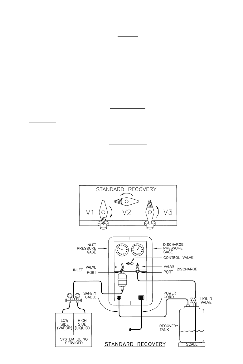
STANDARD RECOVERY
SET UP
1. CONNECT POWER CORD AND SAFETY CABLE OR TEST PLUG.
2. CONNECT CENTER HOSE OF MANIFOLD TO INLET FILTER.
3. CONNECT HOSE ON DISCHARGE PORT TO LIQUID PORT ON TANK.
4. CLOSE INLET VALVE (V1).
5. TURN CONTROL VALVE (V2) TO RECOVER POSITION.
6. OPEN DISCHARGE VALVE (V3).
7. OPEN HIGH SIDE OF SERVICE MANIFOLD.
8. OPEN LIQUID SIDE OF RECOVERY TANK.
OPERATION
1. TURN POWER ON AND PRESS START BUTTON.
2. SLOWLY OPEN INLET PORT (V1).
3. ONCE LIQUID IS RECOVERED OPEN LOW SIDE OF MANIFOLD.
SHUT DOWN
1. CLOSE INLET VALVE (V1) ONCE DESIRED VACUUM IS ACHEIVED.
2. CLOSE LIQUID VALVE ON RECOVERY TANK.
3. CLOSE DISCHARGE VALVE (V3).
4. TURN POWER SWITCH OFF.
2
Page 4

VAPOR RECOVERY
SETUP
1. CONNECT HOSES AS SHOWN BELOW.
2. CLOSE INLET VALVE (V1).
3. TURN CONTROL VALVE (V2) TO RECOVER POSTION.
4. OPEN DISCHARGE VALVE (V3).
5. OPEN LIQUID VALVE ON THE RECOVERY TANK.
OPERATION
1. TURN POWER ON AND PRESS START BUTTON.
2. SLOWLY OPEN INLET VALVE (V1).
SHUT DOWN
1. CLOSE INLET VALVE (V1) ONCE DESIRED VACUUM IS ACHEIVED.
2. CLOSE LIQUID VALVE ON RECOVERY TANK.
3. CLOSE DISCHARGE VALVE (V3).
4. TURN POWER SWITCH OFF.
3
Page 5

PUSH / PULL RECOVERY
(LIQUID RECOVERY FOR 20 LBS. OR MORE)
SET-UP
1. CONNECT HOSES AS SHOWN BELOW.
2. CLOSE INLET VALVE (V1).
3. TURN CONTROL VALVE (V2) TO RECOVER POSTION.
4. OPEN DISCHARGE VALVE (V3).
5. OPEN LIQUID & VAPOR VALVES ON THE RECOVERY TANK.
OPERATION
1. TURN POWER ON AND PRESS START BUTTON.
2. SLOWLY OPEN INLET VALVE (V1).
3. ONCE ALL LIQUID HAS BEEN RECOVERED, GO TO VAPOR
RECOVERY (FIG 2).
SHUT DOWN
1. CLOSE INLET VALVE (V1) ONCE DESIRED VACUUM IS ACHEIVED.
2. CLOSE LIQUID VALVE ON RECOVERY TANK.
3. CLOSE DISCHARGE VALVE (V3).
4.
TURN POWER SWITCH OFF.
4
Page 6

TANK TO TANK TRANSFER
SET-UP
1. CONNECT HOSES AS SHOWN BELOW.
2. CLOSE INLET VALVE (V1).
3. TURN CONTROL VALVE (V2) TO RECOVER POSTION.
4. OPEN DISCHARGE VALVE (V3).
5. OPEN LIQUID VALVE ON THE RECOVERY TANK (A).
6. OPEN LIQUID VALVE ON THE RECOVERY TANK (B).
OPERATION
1. TURN POWER ON AND PRESS START BUTTON.
2. SLOWLY OPEN INLET VALVE (V1).
SHUT DOWN
1. CLOSE INLET VALVE (V1) ONCE DESIRED VACUUM IS ACHEIVED.
2. CLOSE BOTH LIQUID VALVES ON EACH RECOVERY TANK.
3. CLOSE DISCHARGE VALVE (V3).
4.
TURN POWER SWITCH OFF.
(A) FULL TANK (B) EMPTY TANK 5
Page 7

SELF EVACUATION
SET UP
1. CONNECT HOSES AS SHOWN BELOW.
2. CLOSE INLET VALVE (V1).
3. TURN CONTROL VALVE (V2) TO SELF-EVAC POSTION.
4. OPEN DISCHARGE VALVE (V3).
5. OPEN LIQUID VALVE ON THE RECOVERY TANK.
OPERATION
1. TURN POWER ON AND PRESS START BUTTON.
2. SUCTION GAUGE WILL THEN GO INTO A VACUUM.
3. SELF-EVACUATION PROCESS IS COMPLETED.
SHUT DOWN
1. CLOSE LIQUID VALVE ON RECOVERY TANK.
2. CLOSE DISCHARGE VALVE (V3).
3. TURN POWER SWITCH OFF.
6
Page 8

QUICK TEST
With no hose connected, unit plugged in and test plug connected:
1. OPEN both Inlet Valve (V1) and Discharge Valve (V3).
2. PLACE Control Valve (V2) in RECOVER position.
3. Start unit.
Unit SHOULD be sucking on inlet port.
4. CLOSE Inlet Valve (V1).
Suction Gauge SHOULD go into 25” vacuum.
5. OPEN Inlet Valve (V1).
6. CLOSE Discharge Valve (V3).
Discharge Gauge SHOULD build to 150 psig in 30 seconds.
Technical Support
800-848-4232
Mon-Fri 9am to 5pm EST.
TROUBLESHOOTING
SYMPTOM CAUSE CURE
Unit does not start. No power at plug. Check voltage on plug.
Circuit breaker is open. Reset circuit breaker.
Safety cable not connected. Connect both ends.
Test plug not connected. Connect test plug.
Unit starts then shuts off Discharge valve is closed. Open discharge valve.
Tank valve closed. Open valve on tank.
Too much liquid coming in. Partially close inlet valve.
Unit leaks refrigerant. Blown head gaskets. Replace head gaskets.
Loose flare connection. Tighten all connections
Cracked plumbing. Replace plumbing section.
Unit recovers slowly. Tank pressure is too high. Sub-Cool recovery tank.
Inlet filter is clogged. Change the filter.
Unit shuts off during Tank pressure too high. Partially close inlet valve.
Sub-Cool.
7
Page 9

(2) YEAR LIMITED WARRANTY
I.T.S. Thermaflo promises to the owner to repair or, at Thermaflo’s option, to replace any part of the
PowerMax which proves to be defective in workmanship or material under normal use for a period of two
(2) years from date of sale. During this period, Thermaflo will provide all parts and labor necessary to
correct such defects, free of charge.
EXCLUSIONS: 1) Motor: The compressor motor has a (1) year unlimited warranty.
2) Filtering: If during the warranty evaluation it is determined that an
external filter was not used during the operation of the unit, Thermaflo
reserves the right to void the warranty.
In no event will Thermaflo be liable for incidental or consequential damages, or for damages resulting
from external causes such as abuse, misuse, incorrect voltages or acts of God. This warranty does not
cover service calls which do not involve defective workmanship or materials. This warranty gives you
specific rights, and may also have other rights which vary by state.
FOR WARRANTY / NON-WARRANTY REPAIR SERVICE:
1) Call (800) 848-4232 Thermaflo Customer Service. Have model and serial number ready.
2) Thermaflo will then issue a Return Authorization Number (R.A.#) for the repair.
ALL RETURNS MUST HAVE AN R.A. NUMBER PRIOR TO SHIPPING.
3) Ship the product prepaid to:
I.T.S. Thermaflo Repair Dept.
409 Lake Ave.
Bristol, CT 06010
8
Dear Customer:
 Loading...