


DIGIMON-SE DIGIMON4
Installation and operating guide
Digital Manifold
Guide d’installation et d‘utilisation
By-pass électronique
Guía de instalación y funcionamiento
Analizador digital
1

Instruction Manual DIGIMON-SE / DIGIMON4 |
English |
|
|
Instruction manual
2-way and 4-way digital manifolds
DIGIMON-SE
DIGIMON4
1.Low pressure anchor ¼“ SAE
2.High pressure anchor ¼“ SAE
3.Vacuum anchor ¼“ SAE or 3/8“
4.Refrigerants anchor ¼“ SAE
5.Low pressure valve (blue)
6.High pressure valve (red)
7.Vacuum valve (yellow)
8.Refrigerants valve (black)
9.2 external K-type thermocouples
10.Clamp thermocouple K-type (optional) P/N 4681466
11.External vacuum sensor DIGIMON-VAC (optional) P/N 4686713
1

English |
Instruction Manual DIGIMON-SE / DIGIMON4 |
|
Contents |
|
|
Important safety notice ............................................................................. |
|
3 |
Purpose and use ........................................................................................ |
|
3 |
Scope of delivery ...................................................................................... |
|
4 |
Transport .................................................................................................. |
|
4 |
Important note .......................................................................................... |
|
4 |
Technical description ................................................................................. |
|
4 |
Key functions............................................................................................. |
|
6 |
Battery charge level indicator .................................................................... |
|
6 |
Application ................................................................................................ |
|
7 |
Connecting the manifold .......................................................................... |
|
12 |
Evacuating the system ............................................................................. |
|
12 |
Filling the system .................................................................................... |
|
13 |
Measuring using the Superheat / Subcool modes ...................................... |
14 |
|
Maintenance work on the manifold........................................................... |
|
14 |
Guarantee ............................................................................................... |
|
14 |
Environmental issues ............................................................................... |
|
15 |
Replacement parts and accessories |
.......................................................... |
15 |
Resetting pressure sensors ...................................................................... |
|
16 |
Factory settings....................................................................................... |
|
16 |
Resetting the external vacuum sensor...................................................... |
16 |
|
Calibrating pressure sensors .................................................................... |
|
17 |
Calibrating the temperature display ......................................................... |
18 |
|
2

Instruction Manual DIGIMON-SE / DIGIMON4 |
English |
|
|
Important safety notice
 Before working with the manifold, please read the instruction manual carefully. This manual provides important information regarding the smooth operation, maintenance and disposal of the manifold.
Purpose and use
The manifold has been developed for measuring and adjusting pressure and temperature in both mobile and stationary refrigeration equipment.
 The manifold must not be used for anything other than the above-stated purposes.
 The manifold must not be used with pressures higher than 60bar / 870psi / 6000kPa / 6MPa.
 Under no circumstances should the manifold be used as a pressure regulator, especially not when using nitrogen N2.
 The manifold must not be used with the refrigerant ammonia (NH3 / R717).
 The manifold should not be exposed to rain or used in damp or wet environments.
 Protective goggles and gloves must always be worn when using the manifold.
 REFCO products have been specially designed and manufactured for use by trained refrigeration and air-conditioning service engineers only. Due to the high pressures and the physical and chemical gases used in refrigeration systems, REFCO cannot be held liable or responsible for any accidents, injuries or deaths arising during use of the manifold. REFCO explicitly states that their products must only be sold to professionally trained experts.
3

English |
Instruction Manual DIGIMON-SE / DIGIMON4 |
|
|
Scope of delivery
Information about the various models and variations of our products can be found in the REFCO catalogue or at www.refcoswiss.com
Transport
The manifolds are delivered from the factory in a plastic box, with or without filling hoses. Manifolds are high-grade instruments and should always be transported and stored in a box.
Important note:
Remove refrigerants from the manifold and the hoses after use.
The hose connectors hanging freely from the manifold (screw joints / system side) can be screwed onto the Y-connectors and to the central T-piece, when not in use. This serves to protect the thread from contamination and damage.
Technical description
The DIGIMON can be used with the following refrigerants:
R11, R113, R114, R12, R123, R124, R13, R134a, R13B1, R22, R227, R23, R290, R32 R401A(Liq), R401A(Vap), R401B(Liq), R401B(Vap), R402A(Liq), R402A(Vap), R402B(Liq), R402B(Vap), R403B(Liq), R403B(Vap), R404A, R406A (Liq), R406A(Vap), R407A(Liq), R407A(Vap), R407C(Liq), R407C(Vap), R407F(Liq), R407F(Vap), R408A(Liq), R408A(Vap), R409A(Liq), R409A(Vap), R410A, R413A(Liq), R413A(Vap), R414B(Liq), R414B(Vap), R416A, R417A(Liq), R417A(Vap), R420A, R422A(Liq), R422A(Vap), R422B(Liq), R422B(Vap), R422C(Liq), R422C(Vap), R422D(Liq), R422D(Vap), R427A(Liq), R427A(Vap), R437A, R438A(Liq), R438A(Vap), R500, R502, R503, R507, R508A, R508B, R600A, R744, R1234yf
(Liq) = liquid / bubble point, (Vap) = vapour / dew point
4

|
Instruction Manual DIGIMON-SE / DIGIMON4 |
English |
|
|||||
|
|
|
|
|
|
|
|
|
|
|
|
|
|
|
|
|
|
|
Property |
|
Value |
|
|
|
|
|
|
Maximum working |
|
Low pressure: 60bar / 870psi / 6000kPa / 6MPa |
|
||||
|
pressure: |
|
High pressure : 60bar / 870psi / 6000kPa / 6MPa |
|
||||
|
Pressure |
|
0.01 bar / 0.5psi / 1kPa / 0.001MPa |
|
|
|||
|
resolution: |
|
|
|
|
|
|
|
|
Pressure units: |
|
bar / psi / kPa / MPa |
|
|
|
|
|
|
Positive pressure |
|
0 to 60bar, up to 870psi, up to 6000kPa, up to 6MPa |
|
||||
|
display: |
|
|
|
|
|
|
|
|
Negative pressure |
|
0 to -0.95bar, 0 to -13.7psi, 0 to -95kPa, 0 to -0.095MPa |
|
||||
|
display: |
|
|
|
|
|
|
|
|
Accuracy class: |
|
Class 1.0 |
|
|
|
|
|
|
External |
|
Temperature range: |
|
-40°C to +125°C / -40°F to +257°F |
|
||
|
thermocouple: |
|
Plug: |
|
K-type |
|
|
|
|
|
|
Accuracy of |
|
+/- 1.8°F |
|
||
|
|
|
measurement: |
|
|
|
|
|
|
|
|
Resolution: |
|
0.5°C / 0.5°F |
|
||
|
Optional clamp |
|
Temperature range: |
|
-40°C to +125°C / -40°F to +257°F |
|
||
|
thermocouple K- |
|
For pipe diameters of: |
|
6mm to 38mm / ¼“ to 1 ½“ |
|
||
|
type |
|
Plug: |
|
K-type |
|
|
|
|
|
|
Accuracy of |
|
+/- 1.8°F |
|
||
|
|
|
measurement: |
|
|
|
|
|
|
|
|
Resolution: |
|
0.5°C / 0.5°F |
|
||
|
Ambient |
|
0°C to +50°C / +32°F to +122° |
|
|
|||
|
temperature: |
|
|
|
|
|
|
|
|
Power supply: |
|
4 x 1.5 V AA / Mignon / LR6 batteries |
|
||||
|
|
|
Service life of approx. 50 hours when used continuously. |
|
||||
|
Storage |
|
- 20°C to + 60°C / -4°F to 140°F |
|
|
|||
|
temperature: |
|
|
|
|
|
|
|
|
Vacuum display without vacuum sensor |
|
|
|
|
|||
|
|
|
|
|
|
|
|
|
|
Property |
Value |
|
|
|
|
||
|
Vacuum display: |
Bar diagram display |
|
1 bar ca. |
0 to -300mbar |
|
||
|
|
|
|
|
2 bars ca. -300 to -380mbar |
|
||
|
|
|
|
|
3 bars ca. -380 to -460mbar |
|
||
|
|
|
|
|
4 bars ca. -460 to -540mbar |
|
||
|
|
|
|
|
5 bars ca. -540 to -620mbar |
|
||
|
|
|
|
|
6 bars ca. -620 to -700mbar |
|
||
|
|
|
|
|
7 bars ca. -700 to -780mbar |
|
||
|
|
|
|
|
8 bars ca. -780 to -860mbar |
|
||
|
|
|
|
|
9 bars ca. -860 to -920mbar |
|
||
|
|
|
|
10 bars ca. -920 to ultimate vacuum |
|
|||
5
|
English |
|
|
Instruction Manual DIGIMON-SE / DIGIMON4 |
|
|
|
|
|
||
|
Vacuum display with external vacuum sensor |
|
|||
|
|
|
|
|
|
|
Property |
Value |
|
|
|
|
Range: |
0 to 10000 Microns |
|
||
|
Resolution: |
0.1Pa / 1Micron / 0.001mbar / 0.001Torr / 1mTorr / |
|
||
|
|
0.0001psi / |
0.0001inHg |
|
|
|
Units: |
Pa / Micron / mbar / Torr / mTorr / psi / inHg |
|
||
|
Accuracy of |
up to |
100 |
Microns +/- 10 Microns |
|
|
measurement: |
up to |
101 |
- 750 Microns +/- 45 Microns |
|
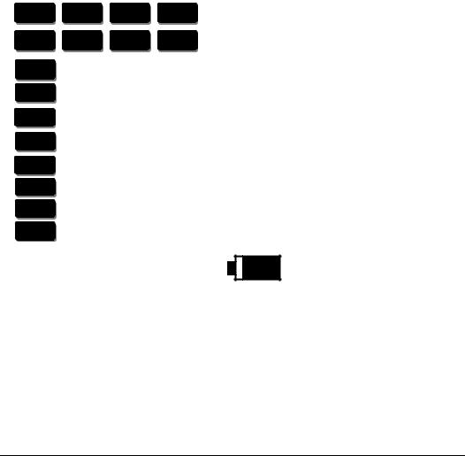
Key functions
R +
SET
ON/OFF
LP/HP
VAC
LIGHT
R +
R -
SUPERH SUBC00L
SET
SUPERH |
LIGHT |
R - |
|
SUBC00L |
|||
|
|
||
VAC |
LP/HP |
ON/OFF |
Power supply ON/OFF
Switch pressure display function
Switch vacuum display function
Switch LCD light on/off (switches off automatically after 1 minute)
Select refrigerant, search forwards (select pressure unit)
Select refrigerant, search backwards (select temperature unit)
Switch function ON or OFF
Confirm function / selection
Battery charge level indicator
If the battery is empty, the indicator will display an entirely white battery symbol. The batteries must then be replaced in order to guarantee full function.
6

Instruction Manual DIGIMON-SE / DIGIMON4 |
English |
|
|
Application
Set-up
Insert 4 batteries in the battery compartment at the back of the device.
Caution: |
Ensure the batteries are inserted observing the correct |
|
|
polarities. Do not leave empty batteries in the battery |
|
|
compartment. If you will not be using the DIGIMON for a |
|
|
longer period of time, remove the batteries from the battery |
|
|
compartment. |
|
Press the |
ON/OFF |
|
button, the device is now switched on. |
||
Check battery charge level indicator.
Illuminating the display
|
LIGHT |
Press the |
button to switch the display light on or off. The light switches off |
automatically after 1 minute.
Automatic shut-off
The DIGIMON switches off automatically approximately 15 minutes after the last measurement or after the last button has been pressed.
Resetting pressure sensors
|
SET |
LIGHT |
By pressing the |
and |
buttons the DIGIMON pressure displays are |
reset to zero, in order to avoid incorrect measurement values.
Important note:
Depressurise the DIGIMON (remove hoses).
Open the blue and red valves.
 To obtain a correct measurement value on the display, the DIGIMON should not be reset when pressurised or under a vacuum.
7
English |
Instruction Manual DIGIMON-SE / DIGIMON4 |
|
|
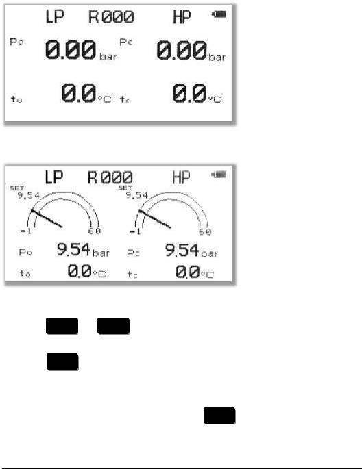
Digital display |
|
|
|
|
|
|
|
|
|
|
|
|
|
|
PSI |
|
PSI |
|
|
|
|
|
|
|
|
|
|
|
|
|
|
|
|
|
|
|
|
|
|
|
|
|
|
|
°F |
|
|
°F |
|
|
|
|
|
|
|
|
|
|
|
|
|
|
|
|
|
|
|
Analogue display with memory function
|
|
|
|
|
|
|
|
|
|
|
|
|
|
PSI |
|
|
|
PSI |
|
|
|
|
|
|
°F |
|
|
|
°F |
|
|
|
|
|
|
|
|
|
|
|
|
||
|
|
|
|
|
|
|
|
|
|
|
|
|
|
|
|
|
|
|
|
|
|
Select refrigerant |
|
|
|
|
|
|
||||
|
R + |
|
R - |
|
|
|
|
|
|
|
Press the |
or |
buttons to select the desired refrigerant from the list. |
||||||||
During selection, you will see a flashing "R" on the display. |
||||||||||
|
SET |
|
|
|
|
|
|
|
|
|
Press the |
button to confirm selection of the desired refrigerant. The "R" no |
|||||||||
longer flashes on the display. |
|
|
|
|
|
|
||||
Important note: |
|
|
|
|
|
|
|
|
|
|
|
|
|
|
|
|
|
SET |
|||
If the refrigerant selection is not confirmed with |
|
|
|
, the previously selected |
||||||
refrigerant will remain active.
8
Instruction Manual DIGIMON-SE / DIGIMON4 |
English |
|
|
Select pressure unit
SET |
R + |
Hold down the |
button. Use |
buttons. |
|
Select temperature unit |
|
SET |
R - |
Hold down the |
button. Use |
both buttons.
Important note:
to select the desired unit. Release both
to choose between °C and °F. Release
The device will save the last pressure and temperature units selected.
Memory function of the analogue pressure display:
|
|
|
SET |
LP/HP |
Save value (current measurement value): press the |
and |
buttons at |
||
the same time |
|
|
|
|
|
LP/HP |
|
|
|
Retrieve memory value: press the |
button for 3 seconds (display freezes) |
|||
LP/HP |
|
|
|
|
Clear display: press the |
button for 3 seconds |
saved value is no longer |
||
visible |
|
|
|
|
|
SET |
LIGHT |
|
|
Delete memory value: press the |
|
and |
buttons at the same time |
|
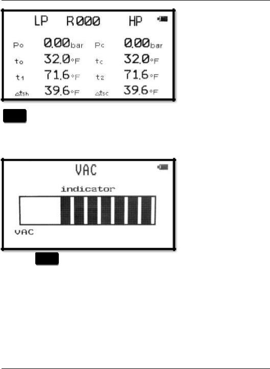
Superheat/Subcool mode
|
|
|
|
|
|
|
|
PSI |
|
|
PSI |
|
|
|
|
|
|
|
|
|
|
|
|
|
|
|
|
|
|
°F |
|
|
°F |
|
|
|
|
|
|
|
|
|
|
|
|
|
|
|
|
|
°F |
|
|
°F |
|
|
|
|
|
|
|
|
|
|
|
|
|
|
|
|
|
°F |
|
|
°F |
|
|
|
|
|
|
|
|
9
Instruction Manual DIGIMON-SE / DIGIMON4
PSI |
|
PSI |
|
|
|
|
|
|
displays the difference "K" (F) between the temperature according to the vapour pressure table (to, tc) and the measured temperature (t1, t2) of the external thermocouples (9) or the clamp thermocouples (10).
Vacuum display
|
VAC |
Press the |
button to bring up the vacuum display. |
Vacuum display values
When evacuating the device, a maximum of 10 bars will be displayed. When the display remains stable, the ultimate vacuum has been reached and the evacuation time begins. The display of the ultimate vacuum (10 bars) depends on the vacuum pump's performance and the atmospheric pressure.
Important note:
The DIGIMON manifold must be switched on before commissioning the attached vacuum pump. The manifold must be switched on during evacuation.
10
Instruction Manual DIGIMON-SE / DIGIMON4 |
English |
|
|
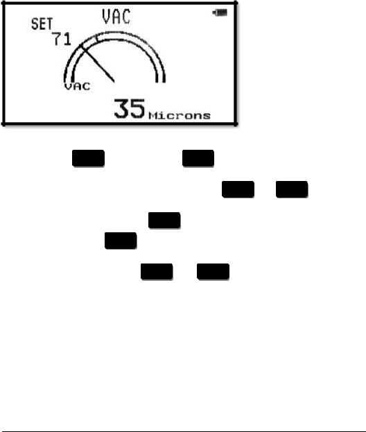
External vacuum sensor (optional)
The external vacuum sensor should be used to measure exact vacuum values. The sensor should be connected to the system.
Vacuum display
Select pressure unit
SET |
|
R + |
|
|
Hold down the |
button. Use the |
button to select the desired unit. |
||
Release both buttons. |
|
|
|
|
|
|
|
SET |
VAC |
Save value (current measurement value): press the |
and |
buttons at |
||
the same time |
|
|
|
|
|
VAC |
|
|
|
Retrieve memory value: press the |
button for 3 seconds (display freezes) |
|||
|
VAC |
|
|
|
Clear display: press the |
button for 3 seconds saved value is no longer |
|||
visible |
|
|
|
|
|
SET |
LIGHT |
|
|
Delete memory value: press the |
and |
buttons at the same time. |
||
11
English |
Instruction Manual DIGIMON-SE / DIGIMON4 |
|
|
Connecting the manifold
a)with DIGIMON-SE
Connect blue hose (1)
Connect red hose (2)
Connect yellow hose (3)
Close both valves (5+6)
b)with DIGIMON4
Connect blue hose (1)
Connect red hose (2)
Connect yellow hose 3/8“ (3)
Connect yellow hose 1/4“ (4)
Close both valves (5+6)
to suction pressure side of system to high pressure side of system to vacuum pump
to suction pressure side of system to high pressure side of system to vacuum pump
to refrigerant cylinder
Evacuating the system
Switch on the manifold
Press the |
VAC |
button |
Connect the hoses
Switch on vacuum pump
Open all valves
Check vacuum display
When the ultimate vacuum is achieved, close all valves.
Press the |
LP/HP |
button to exit vacuum mode. |
 Evacuation time varies depending on the size of the system. A small to medium-sized system requires a minimum evacuation time of 20 minutes.
12

Instruction Manual DIGIMON-SE / DIGIMON4 |
English |
|
|
Filling the system
a)with DIGIMON-SE manifold
Disconnect the yellow hose from the vacuum pump and screw it onto the refrigerant bottle or cylinder.
Open the valve on the refrigerant bottle or cylinder.
Open the blue valve (5) (low pressure side) and let the required amount of refrigerant to flow in. If the required amount of refrigerant does not flow into the system, the compressor must be switched on.
After the system has been filled with the desired amount, close the valve on the refrigerant bottle or cylinder.
Close the blue valve (5).
Check the system's pressure and temperature!
Remove the hoses from the system.
Open valves (5+6).
b)with DIGIMON4 manifold
Disconnect the yellow hose (3/8“) from the vacuum pump and the DIGIMON4
(3)and screw the caps onto the 3/8“ SAE thread.
Open the black valve (8).
Open the valve on the refrigerant bottle or cylinder. Then open the blue valve
(5)and allow the required amount of refrigerant to flow in. If the required amount of refrigerant does not flow into the system, the compressor must be switched on.
After the system has been filled with the desired amount, close the black valve (8).
Close the valve on the refrigerant bottle or cylinder.
Open the red valve (6). Check the pressure and temperature on the high and low pressure sides of the system! If all pressures are in order, close all valves.
Remove the hoses from the system.
Open all valves.
13

English |
Instruction Manual DIGIMON-SE / DIGIMON4 |
|
|
Measuring using the Superheat / Subcool modes
See section "Connecting the DIGIMON manifold".
Plug the K-Type plug of the external thermocouples (9) or the clamp thermocouple (10) into the DIGIMON (sockets on the right (t1) and left (t2) side of the housing).
Fix the external thermocouple (9) or the clamp thermocouple (10) with adhesive tape to the required measuring point on the high pressure or suction pressure side of the system.
Set the appropriate refrigerant (see section "Select refrigerant").
Switch on the temperature difference display: press SUPERHEAT/ SUBCOOL.
Maintenance work on the manifold
A visual inspection of the connections and filling hoses must be carried out before each use, to check for mechanical damage.
Do not use aggressive cleaning agents or solvents to clean the device. Gentle household cleaners and soapy water should be used instead.
Manifold seals are subject to mechanical and age-related wear. Therefore, the manifold should be regularly tested by the user for leaks.
In case of leaky valves, the piston should be replaced (M4-6-04-R/10).
The special REFCO M4-6-11-T tool should be used to change the sight glass on the manifold.
 The manifold should be checked after the replacement of seals to ensure there are no leaks.
Guarantee
Your new DIGIMON has been developed in accordance with the latest occupational health and ergonomic requirements and reflects the latest state-of-the-art technology. REFCO Manufacturing Ltd has been certified in accordance with DIN EN ISO 9001: 2008. Regular quality control checks as well as an accurate manufacturing process guarantee reliable functionality and are the basis for the REFCO guarantee, in accordance with the General Terms and Conditions of Sale and Delivery applicable on the day of delivery. Damages arising from obvious maltreatment or wear are excluded from the guarantee.
14

Instruction Manual DIGIMON-SE / DIGIMON4 |
English |
|
|
Environmental issues
The DIGIMON manifold has been developed for long term use. REFCO takes energy saving and environmental impact into consideration when procuring materials and manufacturing its products. REFCO Manufacturing Ltd feels responsible for all of its products throughout their entire lifespan and has therefore been certified in accordance with DIN EN ISO 14001 : 2004. When decommissioning the device, users should observe the disposal regulations applicable in their country.
Replacement parts and accessories
Description |
Identifier |
P/N |
Control knob red |
M4-7-SET-R |
4677842 |
Control knob blue |
M4-7-SET-B |
4677850 |
Control knob black |
M4-7-SET-N |
4677868 |
Control knob yellow |
M4-7-SET-Y |
4687876 |
Complete valve set |
M2-10-95-R/10 |
4662607 |
Valve piston |
M4-6-04-R/10 |
4662624 |
Sight glass set MS |
M4-6-11 |
4491018 |
Battery compartment cover 2-way |
DIGIMON-SE-BATTERY-COVER |
4686772 |
Battery compartment cover 4-way |
DIGIMON4-BATTERY-COVER |
4686749 |
Tool for sight glass assembly |
M4-6-11-T |
4493169 |
Plastic case |
DIGIMON-SE-CASE |
4676730 |
External K-type thermocouple |
DIGIMON-SENSOR-K-TYPE |
4681394 |
Clamp thermocouple K-type |
DIGIMON CLAMP |
4681466 |
External vacuum sensor |
DIGIMON-VAC |
4686713 |
15

English |
|
Instruction Manual DIGIMON-SE / DIGIMON4 |
|
|
|
Resetting pressure sensors |
|
|
SET |
LIGHT |
|
By pressing the |
and |
buttons the DIGIMON pressure displays are |
reset to zero, in order to avoid incorrect measurement values.
 To obtain a correct measurement value on the display, the DIGIMON should not be reset when pressurised or under a vacuum.
Factory settings
Set the DIGIMON to the "Digital display" screen.
|
LIGHT |
VAC |
|
Press the |
and |
buttons at the same time for 5 seconds. |
|
|
Display shows |
- - - - - - - - |
|
|
SET |
|
|
Press the |
button to exit. |
||
Resetting the external vacuum sensor
Switch off the DIGIMON
Connect vacuum sensor
|
|
VAC |
ON/OFF |
Hold down the |
button and switch on the device using the |
||
|
button. |
|
|
|
Display shows |
VAC-ZERO |
|
|
SET |
|
|
Press the |
button to exit display shows End. |
||
|
|
|
ON/OFF |
The device can be switched on using the |
button and is ready for |
||
operation once again.
16

Instruction Manual DIGIMON-SE / DIGIMON4 |
English |
|
|
Calibrating pressure sensors
 A correct calibration requires a certified monitor. (e.g. REF-CLASS-GAUGE P/N 4682293)
1. Switch off the DIGIMON
|
|
LIGHT |
|
ON/OFF |
2. |
Press down the |
|
button and switch on the device using the |
|
|
button. |
|
|
|
The display shows "Password" 000 |
|
|||
|
R + |
|
R - |
|
3. |
Press the |
/ |
button to select Code 009. |
|
|
SET |
|
|
|
4. |
Press the |
button to exit. |
|
|
The display shows "P-call" |
|
|||
|
R - |
|
|
SET |
5. |
Press the |
button and then the |
button to calibrate. |
|
400 psi should be displayed on the LP side display
 For a correct calibration, there should be no pressure or vacuum in the DIGIMON.
R +
6. Press the button to select the low pressure side's calibration pressure (400psi).
|
|
SET |
|
|
|
7. |
Press the |
button to exit. |
|
|
|
|
|
|
|
SET |
|
8. |
Wait 3-5 seconds until the pressure is stable and press the |
button |
|||
|
again. |
|
|
|
|
|
The display shows "0000" |
|
|
||
9. |
Pressurise the DIGIMON with a calibration pressure of 400psi (27.58 bar). |
||||
|
|
|
|
SET |
|
|
When the pressure is stable, press the |
button to confirm. |
|
||
|
The display shows "LP |
End" |
|
|
|
10. |
The calibration of the low pressure side has been completed. |
|
|||
|
|
R - |
|
|
|
11. Press the |
button to calibrate the high pressure side (HP). Repeat |
||||
|
|
|
ON/OFF |
|
|
|
from Point 6 or press the |
button to end the calibration. |
|
||
17
 Loading...