

Page 1
HVAC/R
Service Products
INSTALLATION OPERATION
AND MAINTENANCE GUIDE
LAC EXTREME
Cooling only, Heat pump and Low Temperature Cut-Off Models
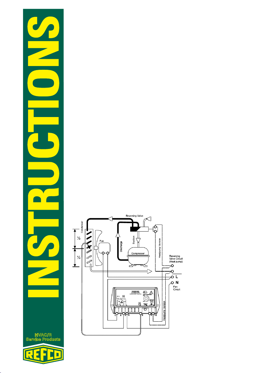
The HPC controllers modulate the condenser fan speed to maintain a constant condensing pressure in heat pumps, air conditioners and refrigeration
plant. This results in higher efficiency, shorter compressor running times,
and more-stable conditions on the evaporator. Over-condensing is eliminated, and freeze-up of air conditioner indoor units is prevented.
COOLING OPERATION
Controlling air movement over the condenser by varying the fan speed
maintains a constant condensing temperature, therefore a constant head
pressure. The condenser temperature is measured midway through the circuit, where the hot gas is condensing. As the condenser temperature rises
and falls, the fan speed automatically increases and slows down to maintain
the head pressure at the set point level. When first powered in the fan runs
at full speed for 10 seconds before controlling to temperature. Note: low
temperature cut-off models need to measure within range before start up.
As temperatures drop the fan speed will fall to its minimum speed. Low
temperatures cut-off models switch off the fan if the temperature continues
to drop: a temperature rise will initiate a 2 second full speed re-start to get
the fan moving. Dual circuit systems are accommodated by the 2-sensor
model where controller responds to the higher of the two temperatures.
Fig. 1 Application Example
REFCO Manufacturing Ltd. Telefon +41 41 919 72 82
Industriestrasse 11 Telefax +41 41 919 72 83
CH-6285 Hitzkirch (Switzerland) Info@refco.ch www.refco.ch
Page 2
HVAC/R
Service Products
HEATING MODE OPERATION
Heat pump models incorporate terminals for connection to the reversing
solenoid valve. The controller is configured to automatically produce 100%
fan speed in heating mode with the reversing valve energised.
SAFETY FIRST
Disconnect all power supplies before starting installation or maintenance
work. The controller and sensor are to be safely enclosed within the housing of the condensing unit, or other enclosure. The controller must be fitted in a dry location, where water cannot fall in to it, or be blown on to it by
the moving fan. The plastic enclosure of the controller is designed to protect
the internal components. There are no user-serviceable parts. All electrical
wiring must be carried out by a competent person, and must comply with
all National and Local Electrical Codes.
FITTING THE CONTROLLER
The Controller should be mounted inside the outdoor unit, protected from
any water dripping on to it, or blown by the fan. The Controller must be
secured to a flat even surface.
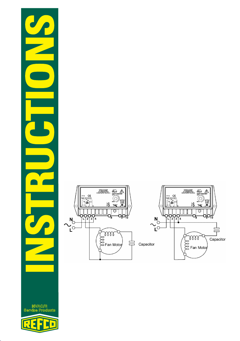
WIRING THE CONTROLLER
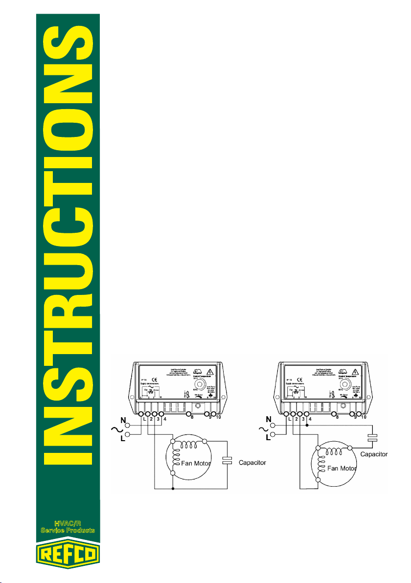
Fig. 2 illustrates the preferred wiring of the Controller. However some fan
motors may control more smoothly when as in Fig. 3.
Fig. 2 Preferred Motor Wiring Fig. 3 Alternative Wiring
REFCO Manufacturing Ltd. Telefon +41 41 919 72 82
Industriestrasse 11 Telefax +41 41 919 72 83
CH-6285 Hitzkirch (Switzerland) Info@refco.ch www.refco.ch
Page 3
HVAC/R
Service Products
Fitting the Sensor
The HPC sensor is fitted to one of the return bends typically mid-way
through the condenser coil circuit, where it can pick up the temperature
of the condensing gas. Wrap tie around twice for small tubes. Use a heat
sink compound between the sensor and the tune for a good thermal bond.
Insulate using foam tape. Do not over-tighten as damage can be caused
to the sensor bead, which is protected by a thin black insulating sleeve is
damaged. On two-sensor models, each sensor should be fitted to its own
section of the condenser, in the centre of the condensing circuit.
Heat pump Models
Where the head pressure controller is to be used with a heat pump, the condenser fan needs to run at full speed during the heating mode, and is only
modulated during the cooling mode. The controller used with heat pumps
therefore have 2 extra terminals which are connected across the reversing
solenoid valve. These then receive a signal feed from either solenoid which
is energised to switch on to heating, and this signal causes the controller to
run the fan at full speed.
Setting Up
The control range of the controller is 30°C to 60°C, and the set point is adjusted by means of the control spindle on the face of the controller. Minimum
speed is factory set for 50Hz operation as standard. Product marked with a
yellow sticker adjacent to the adjuster, indicates that the controller is configured for 60Hz operation. Therefore no further adjustment is necessary.
The minimum fan speed is factory-set to give a motor voltage of 100V for
230V models and 60V for 110V models, which produce a speed of around
30% of maximum, depending in the motor characteristics. Minimum speed
adjustment on low temperature cut-off Models is not advised. To adjust minimum speed, disconnect sensor and switch on unit, fan automatically runs
at minimum speed after hard start, adjust carefully until the fan is running
just fast enough to prevent stalling in windy conditions. Switch off and reconnect sensor.
REFCO Manufacturing Ltd. Telefon +41 41 919 72 82
Industriestrasse 11 Telefax +41 41 919 72 83
CH-6285 Hitzkirch (Switzerland) Info@refco.ch www.refco.ch
Page 4
HVAC/R
Service Products
BEDIENUNGS- UND
WARTUNGSANLEITUNG
LAC EXTREME
Modelle nur für Kühlung, sowie für Wärmepumpen und für die Abschaltung bei niedrigen Temperaturen
HPC-Steuerungen werden zum Abgleich der Lüfterdrehzahl des Kondensators eingesetzt, um einen konstanten Kondensationsdruck in Wärmepumpen, Klimageräten und Kälteanlagen zu erhalten. Dies ermöglicht grössere
Effizienz, kürzerer Kompressor-Betriebszeiten und stabilere Bedingungen
beim Verdampfer. Überkondensation wird vermieden und dem Einfrieren
von Innen-Klimageräten vorgebeugt.
KÜHLBETRIEB
Die Steuerung des Luftstroms über dem Kondensator durch Variieren der
Lüfterdrehzahl ermöglicht eine konstante Kondensationstemperatur und
damit einen konstanten Wasserdruck. Die Kondensations-temperatur wird
auf halber Strecke des Kreislaufs, an der Stelle an der das Heissgas kondensiert, gemessen. Mit steigender und fallender Kondensationstemperatur
steigt die Lüfterdrehzahl automatisch an bzw. fällt automatisch ab, um den
Wasserdruck auf dem Sollwert-Niveau zu halten. Beim ersten Einschalten
läuft der Lüfter zunächst 10 Sekunden lang mit höchster Drehzahl und steuert dann die Temperatur. Hinweis: Modelle zum Abschalten bei niedrigen
Temperaturen müssen vor dem Start innerhalb des Bereichs messen. Mit
fallenden Temperaturen wird die Lüfterdrehzahl bis zur Mindestdrehzahl
verringert. Modelle zum Abschalten bei niedrigen Temperaturen schalten
den Lüfter bei anhaltend fallenden Temperaturen ab: ein Temperaturanstieg
löst einen Neustart mit Betrieb bei höchster Drehzahl für 2 Sekunden aus,
um den Lüfter wieder in Bewegung zu bringen. Das Modell mit 2 Sensoren
enthält ein Zweikreissystem, bei dem die Steuerung auf die höhere der beiden Temperaturen anspricht.
Abb. 1
Anwendungsbeispiel
REFCO Manufacturing Ltd. Telefon +41 41 919 72 82
Industriestrasse 11 Telefax +41 41 919 72 83
CH-6285 Hitzkirch (Switzerland) Info@refco.ch www.refco.ch
Page 5

HVAC/R
Service Products
BETRIEB IM HEIZMODUS
Bei den Modellen für Wärmepumpen sind Anschlüsse zur Verbindung mit
dem Umschaltventil vorgesehen. Die Steuerung ist so konfiguriert, dass im
Heizmodus bei aktivem Umschaltventil automatisch eine Lüfterdrehzahl
von 100% erzeugt wird.
SICHERHEIT
Vor Beginn der Installations- oder Wartungsarbeiten die gesamte Stromversorgung unterbrechen. Die Steuerung und der Sensor müssen fest in
das Gehäuse des Kondensationsgeräts oder in ein anderes Gehäuse eingebaut werden. Die Steuerung ist an einem trockenen Ort anzubringen, wo sie
nicht mit Wasser oder dem Luftzug durch den sich bewegenden Lüfter in
Berührung kommen kann. Das Kunststoffgehäuse der Steuerung ist darauf
ausgelegt, die internen Komponenten zu schützen. Es enthält keine Teile,
die vom Benutzer repariert werden können. Die elektrische Verkabelung
muss von einem Fachmann ausgeführt werden und allen nationalen und
lokalen elektrischen Bestimmungen entsprechen.
ANBRINGEN DER STEUERUNG
Die Steuerung ist im Innern des Aussengeräts, geschützt vor Tropfwasser
und Luft durch den Lüfter, zu montieren. Die Steuerung muss auf einer geraden und ebenen Fläche montiert werden.
VERKABELUNG DER STEUERUNG
Die linke Abbildung zeigt die bevorzugte Verkabelung der Steuerung. Für
manche Lüftermotoren kann jedoch ein Aufbau gemäß rechter Abbildung
besser für einen reibungslosen Betrieb geeignet sein.
Abb. 2 Bevorzugte Verkabelung Abb. 3 Alternative Verkabelung
REFCO Manufacturing Ltd. Telefon +41 41 919 72 82
Industriestrasse 11 Telefax +41 41 919 72 83
CH-6285 Hitzkirch (Switzerland) Info@refco.ch www.refco.ch
Page 6

HVAC/R
Service Products
Anbringen des Sensors
Der HPC-Sensor wird an einem der U-Bogen, normalerweise auf halber
Strecke des Spulenkreises des Kondensators angebracht, wo er die Temperatur des kondensierenden Gases aufnehmen kann. Bei kleinen Schläuchen Kabelbinder zweimal herumwickeln. Zwischen dem Sensor und der
Abstimmung eine Wärmeableitvorrichtung verwenden, um eine gute thermische Verbindung zu gewährleisten. Mit Schaumstoffband isolieren. Nicht
zu fest anziehen, da es sonst zu einer Beschädigung des Sensorflansches,
der durch eine dünne schwarze Isolierhülle geschützt ist, kommen kann.
Bei Modellen mit zwei Sensoren sollte jeder Sensor in einem eigenen Abschnitt des Kondensators in der Mitte des Kondensatorkreises, angebracht
werden.
Wärmepumpen-Modelle
Bei Verwendung der Wasserdruck-Steuerung mit einer Wärmepumpe muss
der Kondensator-Lüfter während des Heizmodus mit voller Drehzahl laufen.
Ein Abgleich erfolgt nur während des Kühlmodus. Für Wärmepumpen verwendete Steuerungen haben daher 2 zusätzliche Anschlüsse, die über das
Umschaltventil verbunden sind. Sie erhalten dann von einem der Ventile,
die zum Anschalten der Heizung aktiviert werden, ein Signal, welches die
Steuerung dazu veranlasst, den Lüfter mit höchster Drehzahl zu betreiben.
Einrichtung
Der Bereich der Steuerung liegt zwischen 30°C und 60°C. Der Sollwert kann
über den Regelschieber an der Vorderseite der Steuerung eingestellt werden. Die Mindestdrehzahl ist standardmäßig ab Werk auf einen Betrieb bei
50 Hz eingestellt. Ein gelber Aufkleber neben dem Einstellelement weist
darauf hin, dass die Steuerung auf einen Betrieb bei 60 Hz konfiguriert ist.
Daher sind weitere Einstellungen nicht erforderlich. Die Mindestdrehzahl
des Lüfters ist ab Werk festegelegt, um eine Motorspannung von 100V für
230V-Modelle zu erreichen, die in Abhängigkeit von den Motoreigenschaften
eine Drehzahl von ca. 30% des Maximums generiert. Die Einstellung der
Mindestdrehzahl bei Modellen zum Abschalten bei niedrigen Temperaturen
wird nicht empfohlen. Zur Einstellung der Mindestdrehzahl den Sensor
trennen und das Gerät einschalten. Der Lüfter läuft nach einem schweren
Start automatisch mit Mindestdrehzahl an. Vorsichtig anpassen bis der Lüfter gerade schnell genug läuft, um einen Ausfall bei windigen Bedingungen
zu vermeiden. Sensor ausschalten und wieder anschliessen.
REFCO Manufacturing Ltd. Telefon +41 41 919 72 82
Industriestrasse 11 Telefax +41 41 919 72 83
CH-6285 Hitzkirch (Switzerland) Info@refco.ch www.refco.ch
Page 7

HVAC/R
Service Products
MANUEL D’UTILISATION
ET D’ENTRETIEN
LAC EXTREME
Refroidissement uniquement, pompe à chaleur et modèles à coupure à
basse température
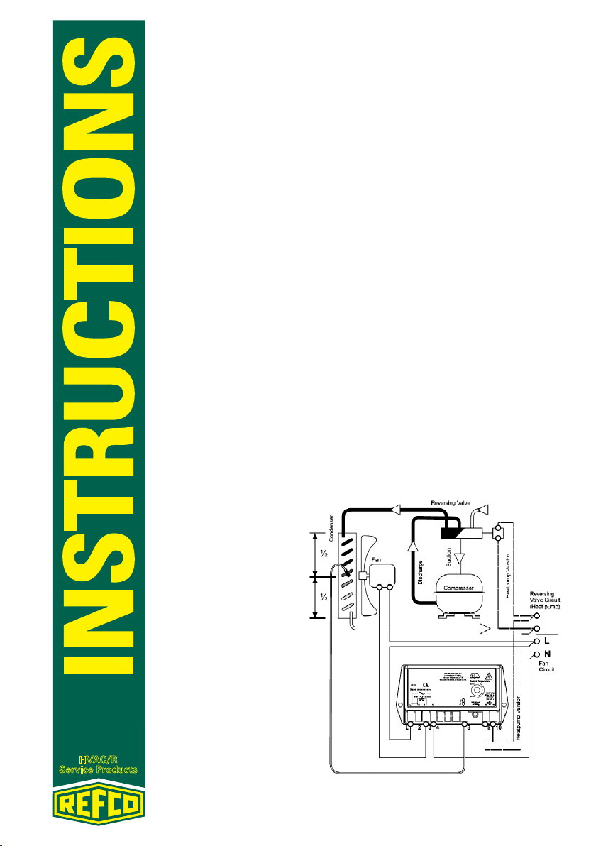
Les contrôleurs HPC (contrôleur de pression de refoulement) modulent la
vitesse du ventilateur du condensateur afin de maintenir une pression de
condensation constante dans les pompes à chaleur, les installations de climatisation et de réfrigération. Résultats: une meilleure efficacité, une réduction des cycles de travail du compresseur et des conditions plus stables
pour l’évaporateur. La sur condensation devient de l’histoire ancienne et les
unités internes de climatisation ne gèlent plus.
REFROIDISSEMENT
Le contrôle des mouvements d‘air via le condensateur en variant la vitesse
du ventilateur permet de maintenir la température de condensation et ainsi
la pression de refoulement constante. La température du condenseur est
mesurée à mi-parcours dans le circuit, là où le gaz chaud se condense. La vitesse du ventilateur augmente et diminue automatiquement à mesure que
la température du condenseur monte et descend, afin de maintenir la pression de refoulement au niveau réglé. Une fois mis en route, le ventilateur
tourne à plein régime pendant 10 secondes avant de contrôler la température. Note: Les modèles à coupure à basse température doivent effectuer
des mesures avant le démarrage. A mesure que la température baisse, la
vitesse du ventilateur diminue jusqu’à la vitesse minimale. Les modèles à
coupure à basse température arrêtent le ventilateur si la température continue de baisser : une augmentation de température entraîne une remise
en marche à plein régime pendant 2 secondes, afin de mettre le ventilateur
en mouvement. Pour les systèmes à double circuit, il existe un modèle à 2
capteurs sur lequel le contrôleur réagit à la plus élevée des températures.
Fig. 1 Example d’utilisation
REFCO Manufacturing Ltd. Telefon +41 41 919 72 82
Industriestrasse 11 Telefax +41 41 919 72 83
CH-6285 Hitzkirch (Switzerland) Info@refco.ch www.refco.ch
Page 8
HVAC/R
Service Products
MODE CHAUFFAGE
Les modèles de pompe à chaleur comprennent des bornes de branchement
à la vanne. Le contrôleur est configuré pour produire automatiquement
100% de la vitesse du ventilateur en mode Chauffage lorsque la vanne inverseuse est alimentée.
LA SECURITE AVANT TOUT
Débrancher toute source d’alimentation électrique avant de commencer les
travaux de montage ou de maintenance. Le contrôleur et le capteur doivent
être montés confinés en toute sécurité dans le boîtier de l’unité de condensation ou dans un autre boîtier. Le contrôleur doit être ajusté monté dans
un endroit sec, où l’eau ne peut tomber ou être projetée dessus par le ventilateur en mouvement. Le boîtier en plastique du contrôleur est conçu pour
protéger les composants internes. Ce dispositif ne contient aucune pièce
pouvant faire l’objet d’un entretien. Tous les câbles électriques doivent être
posés par du personnel compétent et doivent être conformes aux codes
électriques nationaux et locaux.
MONTAGE DU CONTRÔLEUR
Le contrôleur doit être monté à l’intérieur de l’unité externe, à l’abri de tout
écoulement ou toute projection d’eau par le ventilateur. Le contrôleur doit
être fixé sur une surface plane et régulière.
CÂBLAGE DU CONTRÔLEUR
La fig. 2 illustre le câblage recommandé pour le contrôleur. Toutefois certains moteurs de ventilateurs sont susceptibles de mieux fonctionner
lorsqu’ils sont posés comme sur la fig. 3.
Fig. 2 Câblage de moteur recommandé Fig. 3 Câblage alternatif
REFCO Manufacturing Ltd. Telefon +41 41 919 72 82
Industriestrasse 11 Telefax +41 41 919 72 83
CH-6285 Hitzkirch (Switzerland) Info@refco.ch www.refco.ch
Page 9

HVAC/R
Service Products
Montage du capteur
Le capteur HPC est monté sur l’une des coudes de retour, généralement
à mi- parcours du circuit à bobine du condensateur, où il peut détecter la
température du gaz en condensation. Enrouler deux fois l’attache pour les
petits tubes. Utiliser un composé dissipateur de chaleur entre le capteur et
le tube afin de garantir une bonne liaison thermique. Isoler au moyen de
mousse en bande. Ne pas trop serrer sous peine d’endommager la perle du
capteur, qui est protégée par un fin manchon isolant de couleur noir. Sur les
modèles à deux capteurs, chaque capteur doit être fixé à sa propre section
du condensateur, au centre du circuit de condensation.
Modèles de pompes à chaleur
Lorsque le HPC doit être utilisé avec une pompe à chaleur, le ventilateur
de condensation doit fonctionner à plein régime au cours de la phase de
chauffage et être modulé au cours de la phase de refroidissement. Par
conséquent, le contrôleur utilisé avec les pompes à chaleur dispose de 2
bornes supplémentaires qui sont branchées à travers l’électrovanne inverseuse. Celles-ci reçoivent ensuite un signal de celui des solénoïdes qui est
sous tension, leur indiquant de passer en mode chauffage. Le contrôleur fait
alors tourner le ventilateur à plein régime.
Configuration
La gamme de contrôle du contrôleur est de 30°C à 60°C et le point de consigne est réglé au moyen de la tige de contrôle sur la façade du contrôleur.
La vitesse minimale est réglée par défaut en usine pour un fonctionnement
à 50Hz. Le produit marqué identifié par un autocollant jaune juste à côté
de l’instrument d’ajustement, indique que le contrôleur est configuré pour
fonctionner à 60Hz. Aucun autre ajustement n’est alors nécessaire. La vitesse minimale du ventilateur est paramétrée en usine pour donner une tension de moteur de 100V pour les modèles de 230V et de 60V pour les modèles
de 110V, qui produisent une vitesse d’environ 30% de la valeur maximale,
en fonction des caractéristiques du moteur. Il est déconseillé d’ajuster la
vitesse minimale sur les modèles à coupure à basse température. Pour ajuster la vitesse minimale, débrancher le capteur et allumer l’unité, le ventilateur fonctionne alors de manière automatique à une vitesse minimale après
démarrage, ajuster avec prudence jusqu’à ce que le ventilateur tourne juste
à une vitesse suffisante pour empêcher qu’il ne cale en cas de vent. Eteindre
et rebrancher le capteur.
REFCO Manufacturing Ltd. Telefon +41 41 919 72 82
Industriestrasse 11 Telefax +41 41 919 72 83
CH-6285 Hitzkirch (Switzerland) Info@refco.ch www.refco.ch
Page 10

HVAC/R
Service Products
ISTRUZIONI D’INSTALLAZIONE E
DI MANUTENZIONE
LAC EXTREME
Solo raffreddamento, modelli cut-off per pompa di calore e basse temperature
Gli HPC controllo modulano la velocità della ventola del condensatore, alla
fine di mantenere una pressione costante in pompe di calore, condizionatori
d’aria ed impianti di refrigerazione. Ciò produce un livello di efficienza maggiore, dei tempi più brevi di funzionamento per il compressore e condizioni
più stabili nell’evaporatore. Si elimina così l‘eccessiva condensazione e si
contrasta il congelamento delle unità di condizionamento dell‘aria.
RAFFREDDAMENTO
La capacità di monitorare il movimento d’aria in un condensatore, adattando la velocità della ventola, permette di mantenere una temperatura di condensazione costante e, di conseguenza, una pressione di mandata costante.
La temperatura del condensatore viene misurata a metà percorso attraverso il circuito nel quale il gas surriscaldato è in via di condensazione. Se la
temperatura del condensatore aumenta o diminuisce, la velocità della ventola aumenta o si riduce automaticamente, al fine di mantenere la pressione di mandata al valore prescritto. Una volta installato nella ventola opera
a piena velocità per 10 secondi prima di monitorare la temperatura. Nota
bene I modelli per basse temperature cut-off necessitano una misurazione
in un intervallo prima di essere avviati. Quando le temperature si abbassano bruscamente, la ventola gira alla velocità minima possibile. I modelli
per basse temperature cut-off spengono la ventola, qualora la temperatura
continui a scendere. Un aumento di temperatura provoca la piena velocità
per 2 secondi, al fine di riavviare il movimento della ventola. I sistemi circuito doppio sono dotati di due sensori, per i quali il controller reagisce alla
temperatura maggiore fra le due registrate.
REFCO Manufacturing Ltd. Telefon +41 41 919 72 82
Industriestrasse 11 Telefax +41 41 919 72 83
CH-6285 Hitzkirch (Switzerland) Info@refco.ch www.refco.ch
Page 11

HVAC/R
Service Products
MODALITÀ DI RISCALDAMENTO
I modelli di pompe di calore integrano delle connessioni per il collegamento alla valvola solenoide di ritorno. Il controller è configurato per produrre
automaticamente il 100% della velocità della ventola nella modalità di riscaldamento con la valvola solenoide di ritorno sotto tensione.
LA SICUREZZA PRIMA DI TUTTO
Staccare tutti i collegamenti alla corrente di alimentazione, prima di procedere con l’installazione o con la manutenzione. Il controller e il sensore
devono essere chiusi in modo sicuro all’interno del carter dell’unità condensante o altre custodie. Il controller deve essere installato in un punto
asciutto, dove l’acqua non possa infiltrarsi , né possa essere spinta in esso
dalla ventola in movimento. Il carter in plastica del controller è studiato
per proteggere I componenti interni. Non vi sono elementi soggetti a manutenzione da parte del cliente. Tutti I collegamenti elettrici devono essere
realizzati da un tecnico esperto e devono soddisfare le norme nazionali e
valide a livello locale.
INSTALLAZIONE DEL CONTROLLER
Il controller deve essere montato all’interno dell’unità esterna, protetto in
modo da evitare che l‘acqua possa infiltrarsi o possa affluirvi spinta dalla
ventola. Il controller deve essere fissato su una superficie piana e robusta.
CABALAGGIO DEL CONTROLLER
Fig. 2 illustra il cablaggio consigliato per il controller. Tuttavia, alcuni tipi di
ventole a motore possono funzionare a vibrazioni ridotte, rispetto a quanto
riportato alla fig. 3.
Fig. 2. Cablaggio consigliato Fig. 3. Cablaggio alternativo
REFCO Manufacturing Ltd. Telefon +41 41 919 72 82
Industriestrasse 11 Telefax +41 41 919 72 83
CH-6285 Hitzkirch (Switzerland) Info@refco.ch www.refco.ch
Page 12

HVAC/R
Service Products
Installazione del sensore
Il sensore HPC Sensor è installato in una delle piegature di ritorno, generalmente a metà percorso, attraverso il circuito di condensazione a bobine,
dove può rilevare la temperatura del gas condensante. Avvolgere con serra
cavi doppi in caso di tubi stretti. Utilizzare un dissipatore di calore composto
tra il sensore e il sintonizzatore per ottenere un buon ponte termico. Isolare
utilizzando del nastro in schiuma espansa. Non stringere troppo, altrimenti
si potrebbe danneggiare la piccola sfera del sensore, protetta da una sottile
pellicola nera isolante. Nei modelli con due sensori, ogni sensore deve essere installato nella propria sezione del condensatore, al centro del circuito
di condensazione.
Modelli con pompa di calore
Se il controller per la pressione di mandata deve essere impiegato con una
pompa di calore, la ventola del condensatore deve ruotare a piena velocità
nella modalità di riscaldamento e viene modulato solo durante la modalità
di raffreddamento. Il controller usato con pompa di calore ha quindi due
connessioni extra, collegati sopra la valvola solenoide di ritorno. Questi poi
ricevono un segnale dal solenoide sotto tensione per accendersi e riscaldare, mentre il segnale fa sì che il controller faccia operare la ventola alla
massima velocità.
Impostazioni
L’intervallo di monitoraggio del controller è tra 30°C e 60°C e il valore prescritto viene adeguato tramite gli strumenti di controllo posti sul lato anteriore del controller. La velocità minima è impostata dalla fabbrica a
50Hz come standard. I prodotti contrassegnati da un adesivo giallo vicino
al dispositivo di giustificazione indica che il controller è configurato per un
funzionamento a 60Hz. Perciò non è necessaria alcun’altra regolazione. La
velocità minima della ventola è impostata dalla fabbrica per ottenere una
tensione elettrica di 100V per I modelli a 230V e di 60V per i modelli a 110V,
che produce una velocità di circa il 30% del valore massimo, a seconda
delle caratteristiche del motore. Non risulta necessaria una regolazione per
la velocità minima a basse temperature nei modelli cut-off. Per adeguare
la velocità minima, staccare il sensore e accendere l’unità, la ventola gira
automaticamente alla minima velocità e dopo difficoltà di avvio, regolare
con cautela fino a quando la ventola funziona abbastanza velocemente da
evitare un blocco in caso di condizioni critiche. Spegnere e ricollegare poi
il sensore.
REFCO Manufacturing Ltd. Telefon +41 41 919 72 82
Industriestrasse 11 Telefax +41 41 919 72 83
CH-6285 Hitzkirch (Switzerland) Info@refco.ch www.refco.ch
4678678/3408
 Loading...