

Page 1
TAP-CLAMP
TEMPERATURE AND
Installation and operating guide
Temperature And Pressure Gauge
Installations- und Bedienungsanleitung
Temperatur und Druckprüfgerät
Guide d’installation et d‘utilisation
Istruzioni per l’installzione e l’uso
Guía de instalación y funcionamiento
PRESSURE GAUGE
4687787
4687785
TAP
1
Page 2

Instruction Manual TAP, TAP-CLAMP / Temperature And Pressure Gauge English
Contents
Introduction ..................................................................................................................... 2
General information ........................................................................................................ 4
Important safety notice................................................................................................... 5
Technical Data ................................................................................................................. 6
Parts description ............................................................................................................. 8
Transport, packaging and storage .............................................................................. 15
Setup, operation ............................................................................................................ 16
Maintenance .................................................................................................................. 22
Guarantee ...................................................................................................................... 27
Replacement parts and accessories ........................................................................... 27
1
Page 3

English Instruction Manual TAP / Temperature And Pressure Gauge
Introduction
Thank you for your purchase of the REFCO TAP, Temperature And Pressure gauge.
The REFCO TAP wireless digital pressure and temperature gauge is an user friendly
instrument to measure temperature and pressure form the low and high sides of air
conditioning and refrigeration systems.
Features:
- Quick and easy connection to pressure source and temperature measuring point.
- The wireless K-type temperature clamp, equipped with digital display, is applicable for
pipe diameters 6 mm to 41 mm (1/4" to 1-5/8").
- Measurements and calculation of superheat or subcooling can be shown on pressure
gauge display and / or on your mobile device.
- Up to 6 TAP devices can be monitored on your mobile device.
- Create report and send by e-mail to your office.
- Uses common AAA batteries.
- TAP is available in a suitable case either as single or double set.
FCC Part 15.19 Warning Statement
THIS DEVICE COMPLIES WITH PART 15 OF THE FCC RULES. OPERATION
IS SUBJECT TO THE FOLLOWING TWO CONDITIONS: (1) THIS DEVICE MAY
NOT CAUSE HARMFUL INTERFERENCE, AND (2) THIS DEVICE MUST
ACCEPT ANY INTERFERENCE RECEIVED, INCLUDING INTERFERENCE THAT
MAY CAUSE UNDESIRED OPERATION.
2
Page 4

Instruction Manual TAP, TAP-CLAMP / Temperature And Pressure Gauge English
FCC Part 15.21 Warning Statement
NOTE: THE GRANTEE IS NOT RESPONSIBLE FOR ANY CHANGES OR
MODIFICATIONS NOT EXPRESSLY APPROVED BY THE PARTY RESPONSIBLE
FOR COMPLIANCE. SUCH MODIFICATIONS COULD VOID THE USER’S
AUTHORITY TO OPERATE THE EQUIPMENT.
FCC Part 15.105 Warning Statement
Note: This equipment has been tested and found to comply with the limits for a Class B
digital device, pursuant to part 15 of the FCC Rules. These limits are designed to
provide reasonable protection against harmful interference in a residential installation.
This equipment generates, uses and can radiate radio frequency energy and, if not
installed and used in accordance with the instructions, may cause harmful interference
to radio communications. However, there is no guarantee that interference will not occur
in a particular installation. If this equipment does cause harmful interference to radio or
television reception, which can be determined by turning the equipment off and on, the
user is encouraged to try to correct the interference by one or more of the following
measures:
—Reorient or relocate the receiving antenna.
—Increase the separation between the equipment and receiver.
—Connect the equipment into an outlet on a circuit different from that to which the
receiver is connected.
—Consult the dealer or an experienced radio/TV technician for help.
RF warning statement:
The device has been evaluated to meet general RF exposure requirement. The device
can be used in portable exposure condition without restrict ion.
3
Page 5
English Instruction Manual TAP / Temperature And Pressure Gauge
General information
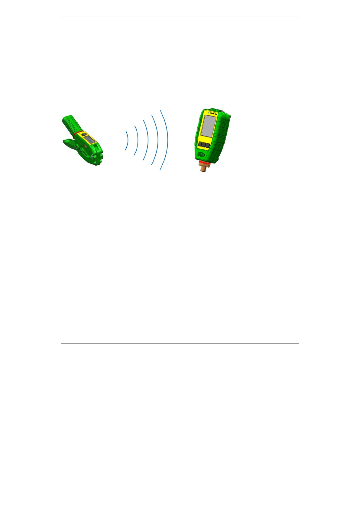
The TAP product consists of:
- A wireless temperature clamp with display to monitor sensible temperature.
- A pressure gauge with display to monitor current pressure and temperatures.
- Up to 6 paired devices can be connected to a smartphone or tablet to observe and
calculate measurements by using the REFCO App.
TAP
Wireless temperature clamp Pressure gauge
The TAP referred to in these operating instructions has been manufactured using stateof-the-art technology. All components are subjected to rigorous quality assurance
criteria during the manufacturing process. Our management systems are certified in
accordance with ISO 9001.
The TAP has been developed for long term use. REFCO takes energy saving and
environmental impact into consideration when procuring materials and manufacturing its
products. REFCO Manufacturing Ltd feels responsible for all of its prod ucts throughout
their entire lifespan and has therefore been certified in accordance with DIN EN ISO
14001 : 2004. When decommissioning the device, users should observe the disposal
regulations applicable in their country.
REFCO products have been specially designed and manufactured for use by trained
refrigeration and air-conditioning service engineers only. Due to the high pressures and
chemical gases used in refrigeration systems, REFCO cannot be held liable or
responsible for any accidents, injuries or deaths arising during use of the TAP. REFCO
explicitly states that their products must only be sold to professionally trained service
engineers.
These operating instructions contain important information about handling the TAP. Safe
operation of the device requires adherence to all safety instructions and operating
guidelines.
4
Page 6
Instruction Manual TAP, TAP-CLAMP / Temperature And Pressure Gauge English
- The local accident prevention regulations applicable to the area in which the TA P
is being used should also be adhered to, along with general safety guidelines.
- The operating instructions are part of the product and must be stored in close
proximity to the TAP where they should be readily accessible to qualified
personnel at all times.
- The qualified personnel must have carefully read and understood the operating
instructions prior to operating the device.
- The manufacturer shall not be liable for any damage whatsoever arising through
improper use, failure to comply with these operating instructions, assignment of
inadequately qualified personnel, or unauthorised modification of the TAP.
- The General Terms and Conditions as set out in the sales documentation shall apply.
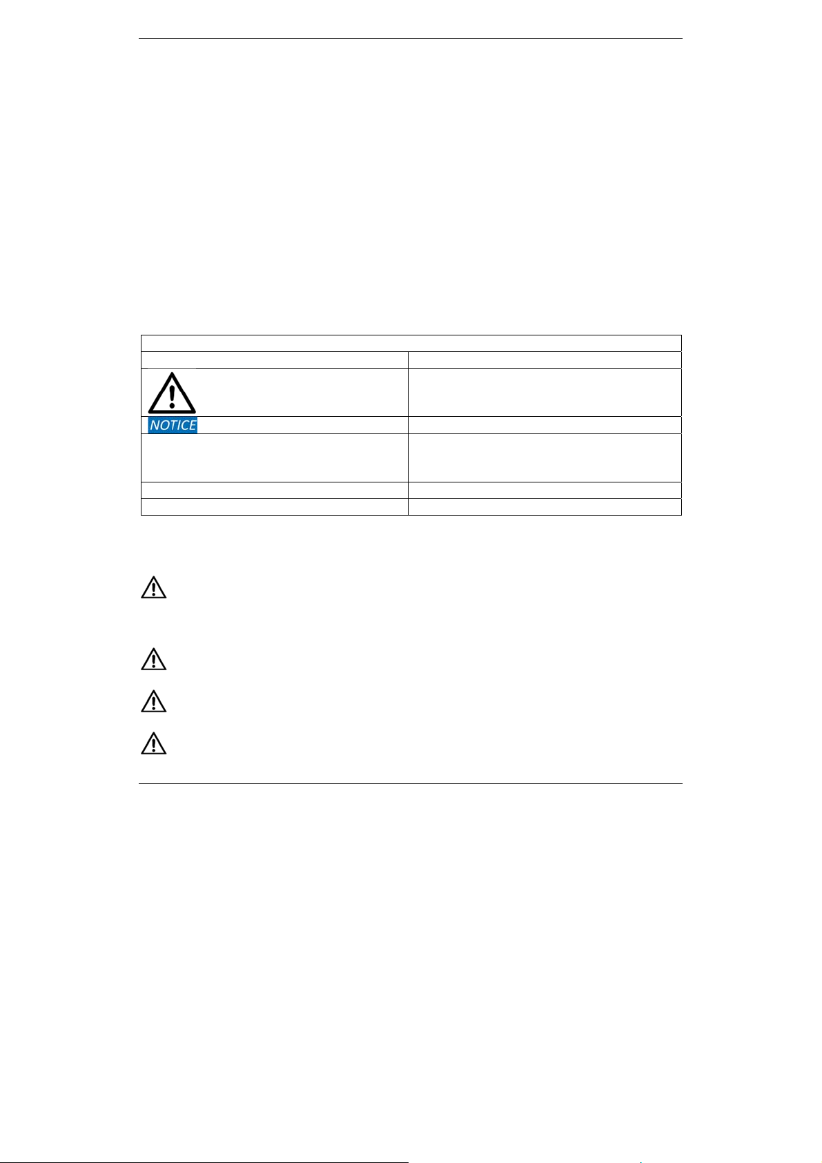
Symbols and writing standards
Illustration Explanation
Warning: Seriuos physical injury can
occur
Caution: Slight physical injury can occur
Damage to the equipment may occur
TAP Temperature and Pressure measuring
device (Temperature clamp + pressure
gauge)
[OK] Control key of the instrument
"OK" Expressions and readouts
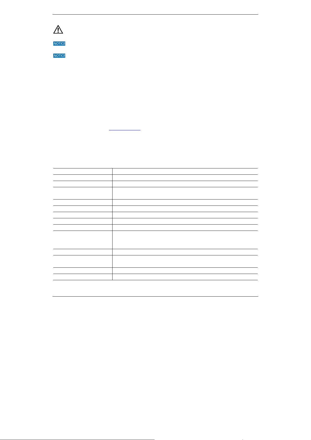
Important safety notice
Before working with the TAP, please read the instruction manual carefully. This
manual provides important information regarding the smooth operation, maintenance
and disposal of the TAP.
The TAP must not be used with pressures higher than 60 bar / 870 psi / 6000 kPa.
Protective goggles and gloves should always be worn when using the TAP.
The TAP must not be used with the refrigerant (NH
/ R-717) ammonia.
3
5
Page 7
English Instruction Manual TAP / Temperature And Pressure Gauge
The TAP must not be used for anything other than the below-stated purposes.
The TAP should not be exposed to moisture or used in damp or wet environments.
Remove refrigerants from the TAP and the hoses after use.
Purpose and use
The TAP has been developed for measuring pressure and temperature in both mobile
and stationary refrigeration equipment.
TAP is only designed for temporary measurement, don`t use it as a stationary long term
measurement unit.
Scope of delivery
Information about the various models and variations of our products can be found in the
REFCO catalogue or at www.refco.ch. The REFCO App is available on App Store and
Play Store.
Technical Data
Temperature clamp
Property Value
Thermocouple: K-type
Temperature range: -40 °C to +125 °C / -40 °F to +257 °F
Accuracy of
measurement:
Resolution: 0.1°C / 0.1°F
Temperature units: °C / °F
Pipe diameters of: 6 mm to 41 mm / ¼" to 1-5/8"
Ambient temperature: 0 °C to +50 °C / +32 °F to +122 °F
Storage temperature: - 20 °C to + 60 °C / -4 °F to 140 °F
Power supply: 3 x 1.5 V AAA / batteries
Backlight LCD display: 35 mm x 15 mm
Automatic power save
mode:
Size: 160 mm x 80 mm x 40 mm
Weight: 180 gr / 6.4 oz
6
+/- 1°C / +/- 1.8°F
Service life of approx. 50 hours when used continuously.
Battery life varies with the brand or age of battery.
Settable to: 10 min / 20 min / Off
Page 8
Instruction Manual TAP, TAP-CLAMP / Temperature And Pressure Gauge English
Pressure gauge
Property Value
Maximum working
pressure:
Pressure resolution: 0.07 bar / 0.1 psi / 7 kPa / 0.007 MPa
Pressure units: bar / psi / kPa / MPa
Positive pressure
display:
Accuracy:
Power supply: 4 x 1.5 V AAA / batteries
Storage temperature: - 20 °C to + 60 °C / -4 °F to 140 °F
Backlit LCD display: 40 mm x 30 mm
Automatic power save
mode:
Interface: Micro USB
Connection fitting: ¼" SAE
Size: 125 mm x 57 mm x 34 mm
Weight: 200 gr / 7.0 oz
The TAP can be used with the following refrigerants:
R11, R113, R114, R12, R123, R124, R13, R134a, R13B1, R22, R227, R23, R290, R32
R401A(Liq), R401A(Vap), R401B(Liq), R401B(Vap), R402A(Liq), R402A(Vap),
R402B(Liq), R402B(Vap), R403B(Liq), R403B(Vap), R404A, R406A (Liq), R406A(Vap),
R407A(Liq), R407A(Vap), R407B, R407C(Liq), R407C(Vap), R407F(Liq), R407F(Vap),
R408A(Liq), R408A(Vap), R409A(Liq), R409A(Vap), R410A, R413A(Liq), R413A(Vap),
R414B(Liq), R414B(Vap), R416A(Liq), R416A(Vap), R417A(Liq), R417A(Vap), R420A,
R422A(Liq), R422A(Vap), R422B(Liq), R422B(Vap), R422C(Liq), R422C(Vap),
R422D(Liq), R422D(Vap), R427A(Liq), R427A(Vap), R437A, R438A(Liq), R438A(Vap),
R448A(Liq), R448A(Vap), R449A(Liq), R449A(Vap), R450A(Liq), R450A(Vap),
R452A(Liq), R452A(Vap), R500, R502, R503, R507, R508A, R508B, R513A, R600a,
R744, R1233zd, R1234yf, R1234ze
(Liq) = liquid / bubble point, (Vap) = vapour / dew point
60 bar / 870 psi / 6000 kPa / 6 MPa
0.95 to 60 bar, up to 870 psi, up to 6000 kPa, up to 6 MPa
1.0% FS
Service life of approx. 35 hours when used continuously.
Battery life varies with the brand or age of battery.
Settable 10 min / 20 min / Off
7
Page 9
English Instruction Manual TAP / Temperature And Pressure Gauge
Parts description
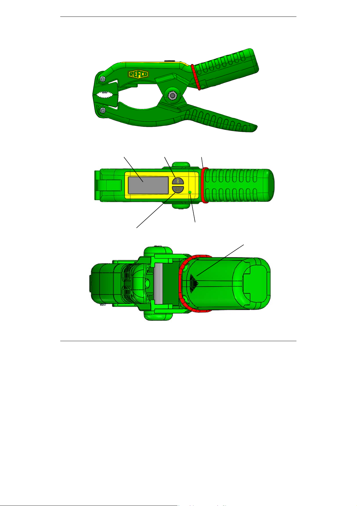
Temperature Clamp
Display
UNIT button
Marking band blue or red
8
ON / OFF button
Indicator LED
light
Battery case cover
3 x 1.5 V AAA
Page 10

Instruction Manual TAP, TAP-CLAMP / Temperature And Pressure Gauge English
A
Pressure Gauge
LED Indicator light
Slider switch
Online / Offline
Battery case cover
4 x 1.5 V AA
Display
ON / OFF
UP
MENU
DOWN
SET
Connection fitting ¼" SAE
Marking band
blue or red
Connection
Micro USB
Mounting ring
9
Page 11

English Instruction Manual TAP / Temperature And Pressure Gauge
Buttons and functions of TAP CLAMP
ON / OFF UNIT
ON / OFF
UNIT
ON / OFF
+
UNIT
ON by short pressing < 1 sec.
- Backlight on
- Start image on
(Backlight shuts off after 1 min.)
Backlight ON/OFF Only in system On-mode by pressing
[ON] < 1 sec. (Backlight shuts off after 1 min.)
Auto Off
- Factory default auto off time = 20 min (configurable)
UNIT by short pressing < 1 sec.
- °C appears
- °F appears
(Once set, setting remains)
By pressing [ON/OFF] + [UNIT] button same time <1 sec. the
following mode is activated:
- Set number of temperature clamp. Scroll from T1 to T6 by pressing
[UNIT] button < 1 sec. (once set, setting remains)
By pressing [ON/OFF] + [UNIT] button same time >1 sec. the
following mode is activated:
- Set Auto Off as required. 10 min / 20 min / OFF.
(Factory default value is 20 min.)
Scroll from 10 / 20 / OFF by pressing [UNIT] button < 1 sec.
(once set, the setting remains)
OFF by pressing 1 sec.
- Display shows "OFF"
- Backlight off
- Display off
UNIT by pressing 1 sec.
- No function
- To escape from last set menu
10
Page 12

Instruction Manual TAP, TAP-CLAMP / Temperature And Pressure Gauge English
Indicator
LED light
Display
Green LED light flashing No LED light
- Power on
- Wireless transmission to
pressure gauge on.
- Power off
- Wirless transmission to
pressure gauge off.
T1.…T6
°C
°F
Number of TAP CLAMP
T1 to T6
Temperature units
Transmiting symbol
Flashing during connection setup.
Constant after connection.
11
Auto Off
10 min. / 20 min. / OFF
Low battery indication
If the battery charge level < 30%, the battery empty
symbol will appear on display. The batteries must then
be replaced within two hours in order to guarantee full
function.
Page 13

English Instruction Manual TAP / Temperature And Pressure Gauge
Buttons and functions on TAP Pressure Gauge
ON / OFF
ON / OFF
ON by short pressing < 1 sec.
- Backlight on
- Start image on
(Backlight shuts off after 1 min.)
Backlight ON/OFF
- Only in system On-modus by short pressing [ O N] < 1 sec.
(Backlight shuts off after 1 min.)
Auto Off
- Factory default auto off time = 20 min.
UP / MENU
UP by short pressing < 1 sec.
- To scroll up
DOWN / SET
DOWN by pressing < 1 sec.
Scroll UP
MENU
OFF by pressing 1 sec.
- Display shows "OFF"
- Backlight off
- Display off
MENU by pressing 1 sec.
- To enter menu mode
- To escape from last set menu
SET by pressing 1 sec.
Scroll DOWN
SET
- To scroll down - To confirm selection
12
Page 14

Instruction Manual TAP, TAP-CLAMP / Temperature And Pressure Gauge English
Indicator LED light
green
Slider
switch
Online Offline
- Wireless transmission to
smart device on
Measurements transmitting
continuous to smart device.
- LED light on.
- Wireless connection to smart
device is active.
- To use TAP with smart device.
Online
- Wireless transmission to
smart device off
No measurements transmitting
to smart device.
- LED light off.
No wirless connection to smart
device.
- To use TAP without smart
device.
- To safe battery life.
Note:
Wirless transmission between temperature clamp and pressure
gauge remains always on. Pressure gauge always receives signal
from temperature clamp if within 10 m / 33 ft of each other.
Offline
13
Page 15

English Instruction Manual TAP / Temperature And Pressure Gauge
Display
P1…P6
To/c
T1..T6
TAP1…TAP6
R000
T
ID of TAP pressure gauge
TAP1 to TAP6
Refrigerants menu
Menu with stored refrigerant charts
bar, psi
kPa, MPa
°C
°F
°C
°F
K
°F
Settings
Transmiting symbol
Flashing during connection setup.
Constant after connection.
Low battery indication of TAP pressure gauge
If the battery charge level < 30%, the battery
empty symbol will appear on display. The
batteries must then be replaced within two hours
in order to guarantee full function.
Pressure units
(P) = Pressure
Temperature units
(To = Evaporating temperature )
(Tc = Condensing temperature)
Temperature units
(T) = Temperature from temp. clamp
Temperature difference
(T) = Temperature difference
14
Low battery indication of connected TAP
CLAMP
Page 16

Instruction Manual TAP, TAP-CLAMP / Temperature And Pressure Gauge English
Transport, packaging and storage
Transport
The TAP is delivered from the factory in a plastic box, with or without different
accessories as ordered. Inspect the TAP for any potential transportation damage. Any
obvious damage should be reported to the vendor immediately.TAP is a high-grade
instrument and should be transported and stored in a box, for long term protection.
Packaging
Retain the original packaging as it provides optimum protection for transportation of the
device (e.g. onward dispatch of the device, sending it for repair etc.).
Storage
- Storage temperature: -20 °C to +60 °C
- Humidity: 0 to 90% relative humidity (no condensation)
15
Page 17

English Instruction Manual TAP / Temperature And Pressure Gauge
Setup and operation
TAP CLAMP
Set-up
TAP CLAMP
Insert 3 x 1.5 V (AAA) batteries in the battery compartment
of the TAP CLAMP.
Switch on
Set
TAP CLAMP
ID
Ensure the batteries are inserted observing the correct polarities. Do
not leave dead batteries in the battery compartment. If you will not be
using the TAP CLAMP for a long period of time, remove the batteries
from the battery compartment.
- Press [ON/OFF] button, to switch on device.
After start image, display appears
- Press [ON/OFF] + [UNIT] button same time < 1 sec. to enter set
mode.
- Scroll from T1 to T6 by pressing [UNIT] button < 1 sec.
- Press [ON/OFF] button 1 sec. to confirm and return to main
display.
Note:
Chosen ID will be transmitting to pressure gauge and is
shown on display.
16
Page 18

Instruction Manual TAP, TAP-CLAMP / Temperature And Pressure Gauge English
Set Auto Off
Note:
Set unit
TAP Pressure Gauge
Set-up TAP
- Press [ON/OFF] + [UNIT] button same time >1 sec. to enter set
mode.
- When Auto Off mode is activated timer symbol appears.
- Scroll from 10 / 20 / OFF by pressing [UNIT] button <1 sec.
- Press [ON/OFF] button 1 sec. to confirm and return to main menu.
Factory default Auto Off is set to 20 min.
Subsequent the symbol and the auto off time disappear from display.
- Press [UNIT] button < 1sec.
- Switch between °C and °F by using [UNIT] button <1 sec.
Insert 4 x 1.5 V (AAA) batteries in the battery compartment on the
back side of the TAP.
Ensure the batteries are inserted observing the correct polarities. Do
Switch on
17
not leave dead batteries in the battery compartment. If you will not be
using the TAP pressure gauge for a long period of time, remove the
batteries from the battery compartment.
- Press [ON] button to switch on device.
After start, REFCO-logo appears on display.
Page 19

English Instruction Manual TAP / Temperature And Pressure Gauge
Set TAP ID
Note:
Set
refrigerant
- Press [MENU] button
TAP ID menu is selected.
- Press [SET] button
- Choose a TAP ID number by pressing [UP] or [DOWN] button
< 1 sec.
- Press [SET] button
- Press [MENU] button
Number for P1 to P6 is always concurrent with the TAP number.
To change current refrigerant setting:
- Press [MENU] button
- Press [DOWN] button
menu.
- Press [SET] button
- Press [UP] or [DOWN] button
refrigerant type entry.
- Press [SET] button
- Press [MENU] button
1 sec. to activate selection mode.
1 sec. to enter TAP ID menu.
1 sec. to confirm selected ID.
1 sec. to return to main display.
1 sec. to activate selection mode.
1 sec. to scroll down to the refrigerant
1 sec. to enter refrigerant menu.
1 sec. to scroll to the desired field
1 sec. to confirm.
1 sec. to return to main display.
Note:
The first 6 refrigerants can be favorites.
Following are all known refrigerants from library.
18
Page 20

Instruction Manual TAP, TAP-CLAMP / Temperature And Pressure Gauge English
Note on R000:
Additional function to select from table of refrigerant: If use entry
„R000“ it means „Pressure only“. No readouts from chart. It gives the
possibility to measure only pressure and temperature without any
refrigerant chart temperatures shown.
Set favorites
Note:
Set pressure
unit
- Press [MENU] button
- Press [DOWN] button
menu.
- Press [SET] button
- Press [UP] or [DOWN] button
refrigerant.
- Press [ON/OFF] button < 1 sec. to add refrigerant to favorites.
New favorite is placed at first of column.
Last of the 6 entries drops out.
- Press [MENU] button
- Press [DOWN] button
menu.
- Press [SET] button
- Press [UP] or [DOWN] button
- Press [SET] button
- Press [MENU] button
1 sec. to activate selection mode.
1 sec. to scroll down to the refrigerant
1 sec. to enter refrigerant menu.
1 sec. to scroll to the desired
1 sec. to activate selection mode.
1 sec. to scroll down to the pressure unit
1 sec. unit field will flash.
1 sec. to select pressure unit.
1 sec. to confirm.
1 sec. to return to main display.
19
Page 21

English Instruction Manual TAP / Temperature And Pressure Gauge
Set
temperature
unit
Pairing
- Press [MENU] button
- Press [DOWN] button
unit menu.
- Press [SET] button
- Press [UP] or [DOWN] button
- Press [SET] button
- Press [MENU] button
-Ensure the distance between the devices is less than 5 meters.
- Ensure TAP CLAMP(S) which shall be paired with TAP pressure
gauge are switched on.
- Ensure TAP pressures gauge is on.
- Press [MENU] button
selection mode.
- Press [DOWN] button
down to the field "T".
- Press [SET] button
Display of TAP pressure gauge shows "Scan…"
Note:
If no device can be found, "No Signal" appears on display before
return to menu.
- If device be found, display shows a list of found TAP CLAMP ID(s).
- Select desired TAP CLAMP ID by pressing [UP] or [DOWN] button
1 sec. to activate selection mode.
1 sec. to scroll down to the temperature
1 sec. unit field will flash.
1 sec. to select temperature unit.
1 sec. to confirm.
1 sec. to return to main display.
1 sec. on TAP pressure gauge to activate
1 sec. of TAP pressure gauge to scroll
1 sec. to start scanning.
1 sec.
- Press [SET] button
During pairing procedure, display shows " Connect…".
1 sec. to start pairing.
20
Page 22

Instruction Manual TAP, TAP-CLAMP / Temperature And Pressure Gauge English
If pairing was successful, display shows "END".
Paired TAP CLAMP is recognised on TAP display with T and relevant
number (1 to 6).
- If pairing was not successful, display shows "ERROR“. If this
happens, repeat steps above and try again.
Change
Settings
- Press [MENU] button
- Press [UP] button
- Press [SET] button
- Press [UP] or [DOWN] button
Available fields:
Auto Off
Update
Version
SD Mode
P-Zero
- Press [SET] button
1 sec. to activate selection mode.
1 sec. to scroll up to the setting field .
1 sec. to enter settings menu.
1 sec. to confirm.
1 sec. to scroll to the desired field.
Update
Version
21
Auto Off
- Press [UP] or [DOWN] button
option. (10 min. / 20 min. / Off)
- Press [SET] button
Updating refrigerants.
See in chapter maintenance.
Current version of refrigerant chart is shown.
1 sec. to confirm.
1 sec. to choose the auto shutoff
Page 23

English Instruction Manual TAP / Temperature And Pressure Gauge
SD Mode
P-Zero
This function is used in combination for update.
See in chapter maintenance.
Resetting pressure sensor.
See in chapter maintenance / Resetting pressure sensor
Maintenance
A visual inspection of the connections and hoses must be carried out before
each use to check for mechanical damage.
Do not use aggressive cleaning agents or solvents to clean the device. Gentle
household cleaners and soapy water should be used instead.
TAP seals are subject to mechanical and age-related wear. Therefore, the TAP
should be regularly tested by the user for leaks.
Resetting pressure sensore on TAP pressure gauge
The TAP pressure sensor can be reset in order to avoid incorrect measurement values.
P-Zero
To obtain a correct measurement value on the display, the TAP should not
be reset when pressurised.
1. Ensure TAP pressure gauge is switched on.
2.
Press [MENU] button
1 sec. to activate selection mode.
3.
Press [UP] button
4.
Press [SET] button
5.
Press [UP] or [DOWN] button
6.
Enter "P-Zero" by pressing [SET] button
7. Display shows 0.0psi
8.
Press [SET] button
9. Display shows setting menu.
10.
Press [MENU] button
22
1 sec. to scroll up to the setting field .
1 sec. to enter settings menu.
1 sec. to scroll to the "P-Zero" field.
1 sec. for confirmation.
1 sec. to quit.
1 sec.
Page 24

Instruction Manual TAP, TAP-CLAMP / Temperature And Pressure Gauge English
Updating of refrigerants on TAP pressure gauge via Micro USB
The TAP pressure gauge supports updates of refrigerant data via Micro USB.
The latest refrigerant charts can be found at www.refco.ch
Updating refrigerants
1. Ensure TAP pressure gauge is switched on.
2.
Press [MENU] button
3.
Press [UP] button
4.
Press [SET] button
1 sec. to activate selection mode.
1 sec. to scroll up to the setting field .
1 sec. to enter settings menu.
5.
Press [UP] or [DOWN] button
6. Enter "SD Mode" , select "USB MSC".
7. Connect TAP to computer by USB connection; the device shown on computer.
8. Copy the file "Refriger .bin" to the folder "Refriger" which is under the device.
9. Disconnect the TAP from computer.
10. Enter "SD Mode" , select "SD FAFS"
11. Enter "Update" (MENU) to update the refrigerant data.
1 sec. to scroll to the "SD Mode" field.
23
Page 25

English Instruction Manual TAP / Temperature And Pressure Gauge
Calibration
The accuracy of all measuring devices will degrade over time. Calibration improv es the
accuracy of the TAP. On this device temperature and pressure can be re-calibrated.
Temperature calibration can be done using two procedures: calibrat ion using ice water
as reference or by using room temperature as reference.
Calibration of temperature clamp
Risk of short circuit. If the electronic components come into contact with
water, short circuits are possible. Don`t dunk the temperature clamp below
max. water level. (See figure below)
Ice water calibration (0 °C / 32 °F)
Risk of short circuit. If the electronic components come into contact with
water, short circuits are possible. Dunk the temperature clamp below max.
water level as shown.
1. Prepare ice water:
Take your time, use lots of ice and stir water often. It can take
up to 15 minutes for the ice water temperature to settle exactly
at 0.0 °C / 32.0 °F Use separate accurate thermometer to
verify water temp.
For best results use an insulated cup, do not let the sensor
tips touch any ice cubes, only the ice water in the top 2-3 cm
of the ice bath after +/- 15 min. Do not touch or hold the
sensor wires.
24
Page 26

Instruction Manual TAP, TAP-CLAMP / Temperature And Pressure Gauge English
2. Turn off the clamp.
3. While holding [UNIT], press [ON / OFF] until display shows "CALL"
4. Release both buttons, the display shows "00"
5. Press [UNIT] button < 1 sec. to adjust the number to "06"
6. Press [ON / OFF] button < 1 sec., the display shows "00 °C"
7. Press [UNIT] button < 1 sec. to show a code of temperature
8. Put the K – thermocouple (plate) into 0 °C ice water.
9. Wait the temperature code reading to be steady, press [UNIT] button < 1 sec.
10. The display shows the ambient temperature.
11. Press [UNIT] button < 1 sec. to quit the temperature calibration.
Room temperature calibration
1. Turn off the clamp.
2.
Place the clamp at constant temperature at 25
3 °C condition for 2 hrs. to ensure
the temperature of the K – thermocouple to be even.
3. While holding [UNIT], press [ON / OFF] until display shows „CALL“
4. Release both buttons, the display shows „00“
5. Press [UNIT] button < 1 sec. to adjust the number to „09“
6. Press [ON / OFF] button < 1 sec. to show a code of temperature.
7. Wait the temperature code reading to be steady, press [ON / OFF] button < 1 sec.
8. The display shows the ambient temperature.
9. Press [ON / OFF] button < 1 sec. to quit the temperature calibration.
25
Page 27

English Instruction Manual TAP / Temperature And Pressure Gauge
Calibration of pressure gauge
Pressure calibration
1. Turn off the TAP.
2. While holding [UP / MENU] button, press [ON / OFF] button, the display shows
„P-CALL“
3. Press [DOWN / SET] button until the display shows „Password 00“
4. Press [UP / MENU] button shortly to adjust the number to „Password 8“
5. Press [DOWN / SET] button until the display shows a reading which is presenting the
unload pressure. (i.e. 0.0 psi)
6. Press [DOWN / SET] awhile to enter calibration
Ensure all the refrigerant is exhausted from TAP valve or connected hoses
before performing calibration. The accuracy will be affected due to the
remaining refrigerant.
7. While entering calibration, the display shows „400.0 psi“. The default pressure of
calibration standard is 400 psi.
8. Press [UP / MENU] button shortly to select the calibration standard. The inlet
pressure must be equal to the calibration standard pressure.
9. Press [DOWN / SET] awhile for calibration standard confirmation; the display shows
the reading of unloaded pressure.
10. Wait until the reading of unload pressure ist stable, pressuirze 400 psi (the inlet
pressure must be equal to the calibration standard pressure). The display shows the
corresponding pressure value (i.e. 400.0 psi)
11. When the reading is stable, press [DOWN / SET] for confirmation. Now the display
shows „END“
12. Press [DOWN / SET] awhile to quit the pressure calibration.
26
Page 28

Instruction Manual TAP, TAP-CLAMP / Temperature And Pressure Gauge English
Guarantee
Your new TAP has been developed in accordance with the latest occupational health
and ergonomic requirements and reflects the latest state-of-the-art technology. REFCO
Manufacturing Ltd has been certified in accordance with DIN EN ISO 9001: 2008.
Regular quality control checks as well as an accurate manufacturing process guarante e
reliable functionality and are the basis for the REFCO guarantee, in accordance with the
General Terms and Conditions of Sale and Delivery applicable on the day of delivery.
Damages arising from obvious maltreatment or wear are excluded from the guarantee.
Return and disposal
Dispose of faulty rechargeable batteries/spent batteries in accordance with the valid
legal specifications. At the end of its useful life, send the product to the separate
collection for electric and electronic devices (observe local regulations).
Replacement parts and accessories
Description Identifier P/N
TAP pressure gauge TAP 4687787
TAP clamp TAP-CLAMP 4687785
¼“ SAE hose red CL-6-R 9881265
¼“ SAE hose blue CL-6-B 9881256
¼“ SAE hose yellow CL-6-Y 9881274
Quick coupler straight ¼“ SAE QC-S4A-1/4"SAE 4687736
Quick coupler straight ½“-20UNF QC-S4A-1/2"-20UNF 4687737
Swivel Arm ¼“ SAE-N SWIVEL-ARM-1/4"SAE-N 4687631
Threaded T-style SAE ¼“
female with swivel nut
Adapter ¼“ SAE x ½“-20UNF QC-S410A/2 4687095
Swivel adapter
3/8“ SAE male x ¼“ SAE female
A-31851/10 9884841
QC-S4-3/8"x1/4"/2 4687406
27
Page 29

Page 30

Deutsch Bedienungsanleitung DIGIMON / DIGIMON4
REFCO Manufacturing Ltd.
Industriestrasse 11
6285 Hitzkirch - Switzerland
Telefon +41 41 919 72 82
Telefax +41 41 919 72 83
info@refco.ch
www.refco.ch
4687790
1
 Loading...