

Page 1

Distributed by
Any reference to Raytheon or
RTN in this manual should be
interpreted as Raymarine.
The names Raytheon and RTN
are owned by the
Raytheon Company.
Page 2

ST80
Maxiview
Operation & Setup
Page 3

Maxiview
Page 4

ST80 Maxiview Operation and Setup
Package Contents
1. Maxiview display head
2. Thumb nuts (2)
3. Threaded fixing studs (2)
4. White sun cover
5. SeaTalk cable
6. Installation template
7. Operation manual
8. Warranty card
9. Operation cue card
10. Display head installation guide
1
Page 5

Contents
ST80 Maxiview Operation and Setup2
Chapter 1: Introduction ............................................................. 7
Quick Reference Guide ............................................... 7
Chapter 2: Operation ............................................................... 10
2.1 General ...................................................................... 10
Operating the Maxiview using the Remote Keypad .... 10
Keypad Beeps ........................................................... 10
Gaining Control of the Maxiview ........................ 10
2.2 Speed Chapter ............................................................ 11
Boat Speed Page........................................................ 11
Speed Over Ground (SOG) Page ................................ 12
Velocity Made Good (VMG) to Wind Page ................ 12
Log/Trip Page ........................................................... 13
Average Speed .......................................................... 14
Maximum Speed Page............................................... 14
2.3 Depth Chapter ............................................................ 15
Depth Page................................................................ 15
Minimum Depth Page ............................................... 16
Depth Offset Page ..................................................... 16
2.4 Wind Chapter ............................................................. 17
Apparent Wind Speed page ....................................... 17
Apparent Wind Angle Page ....................................... 17
True Wind Speed Page (Relative to the Vessel) .......... 18
True Wind Angle (Relative to the Vessel) .................. 18
True Wind Angle (Referenced to the Compass) .......... 19
2.5 Heading Chapter......................................................... 19
Heading Page ............................................................ 19
Steering Page ............................................................ 20
Course Over Ground (COG) Page .............................. 20
Bearing to Waypoint (BTW) Page ............................. 21
Tack Course Page...................................................... 21
Page 6

ST80 Maxiview Operation and Setup
2.6 Navigate Chapter........................................................ 22
2.7 Race Timer Chapter.................................................... 26
2.8 Multi-Line.................................................................. 27
2.9 Illumination ............................................................... 31
2.10 Data Lost.................................................................. 32
2.11 Man Overboard and Alarms ...................................... 32
3
Position Page............................................................. 22
Course Over Ground (COG) & Bearing to Waypoint
(BTW) ...................................................................... 22
Cross Track Error ...................................................... 23
Velocity Made Good (VMG) to Waypoint Page ......... 23
Waypoint Data Page.................................................. 24
Date/Time/Tide Page ................................................ 25
Race Start Page ......................................................... 26
Help/Setup Page........................................................ 27
Multi-line Setup ........................................................ 28
List of Multi-line Selections ................................ 29
Multi-line Factory Defaults ................................. 30
Resetting the Contrast................................................ 32
Man Overboard ......................................................... 32
Dead Reckoned MOB......................................... 32
Lat/Lon MOB ........................................................... 33
Incomplete MOB Data .............................................. 33
MOB Audible Alarm .......................................... 34
Alarms ...................................................................... 34
Audible Alarms ......................................................... 35
Page 7

ST80 Maxiview Operation and Setup4
Chapter 3: Setup ...................................................................... 36
3.1 Entering Setup ............................................................ 36
Speed Chapter ........................................................... 37
Response Pages .................................................. 37
Trend Indicator Thresholds ................................. 38
Display Format................................................... 40
Depth Chapter ........................................................... 40
Depth Response.................................................. 41
Trend Indicator Thresholds ................................. 41
Depth Display Format......................................... 42
Wind Chapter............................................................ 42
Wind Speed Response ........................................ 43
Win d An gl e R es po ns e ........................................ 43
Display Format................................................... 44
Multiline Chapter ...................................................... 44
Editing Rights .................................................... 45
3.2 Instrument Setup ........................................................ 46
Transducers Page ...................................................... 46
Sail/Power/Custom Selection .................................... 47
Custom .............................................................. 48
Contents Setup ................................................... 49
Title Control....................................................... 50
Variation ............................................................ 51
True/Magnetic Heading...................................... 52
Lamp Offset Adjustment .................................... 53
Contrast Adjustment ........................................... 54
LCD Inversion ................................................... 55
Alarm Control .................................................... 56
3.3 Quitting User Setup .................................................... 57
Page 8

ST80 Maxiview Operation and Setup
Chapter 4: CodeLock Security................................................. 58
4.1 What is CodeLock? .................................................... 58
4.2 Analogue Display Heads............................................. 59
4.3 Enabling CodeLock.................................................... 59
Chapter 5: Problem Solving..................................................... 60
Chapter 6: EMC and Servicing Guidelines .............................. 61
6.1 Important information................................................. 61
6.2 Installation ................................................................. 61
6.3 Check Before Going to Sea ......................................... 62
6.4 Servicing and Safety ................................................... 62
Chapter 7: Specification ......................................................... 63
5
Master’s .................................................................... 58
Slave’s ...................................................................... 58
Automatic CodeLock Systems................................... 59
Manual CodeLock System......................................... 59
Page 9

ST80 Maxiview Operation and Setup6
Page 10

ST80 Maxiview Operation and Setup
Chapter 1: Introduction
SPEED
The Maxiview is a large-screen LCD repeater capable of displaying
single or multiple lines of alphanumeric SeaTalk data.
With a display area measuring 126 x 70mm (5 x 2.7in), the
Maxiview provides a clear and unambiguous display wherever you
are on your boat.
Unlike the other ST80 display heads, the Maxiview has a key-less
facia. All user functions are controlled from the ST80 Remote
Keypad or, alternatively, a Masterview with the “Maxiview remote
control mode” chapter enabled.
7
maxiview
KNOTS
D1580-1
Quick Reference Guide
The illustration on the following two pages provides a quick
reference guide to the complete range (Sail configuration) of the
Maxiview chapters and pages.
The Maxiview can be set to ignore the sail/power chapter and page
selections and display user-defined custom selections. For further
information on making custom selections, please refer to the Sail
and Power Selection Page.
Page 11

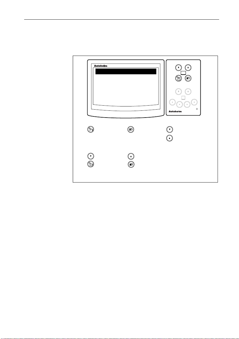
maxiview
maxiview
remote
Press this key momentarily to cycle
the available chapters.
Press and hold for 1 second to select
illumination adjustment. Additional
key presses change the illumination
setting.
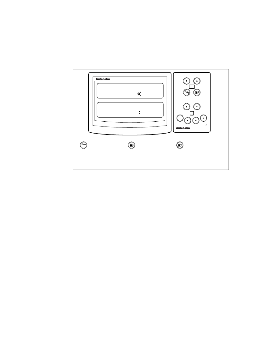
Press this key momentarily to cycle
pages within the currently selected
chapter.
Press and hold for 1 second to return to
the previous page.
Use the arrow keys to select another
Maxiview display.
Note:
The selected Maxiview display head
changes to reverse video.
The Maxiview can also be operated
from a Masterview display.
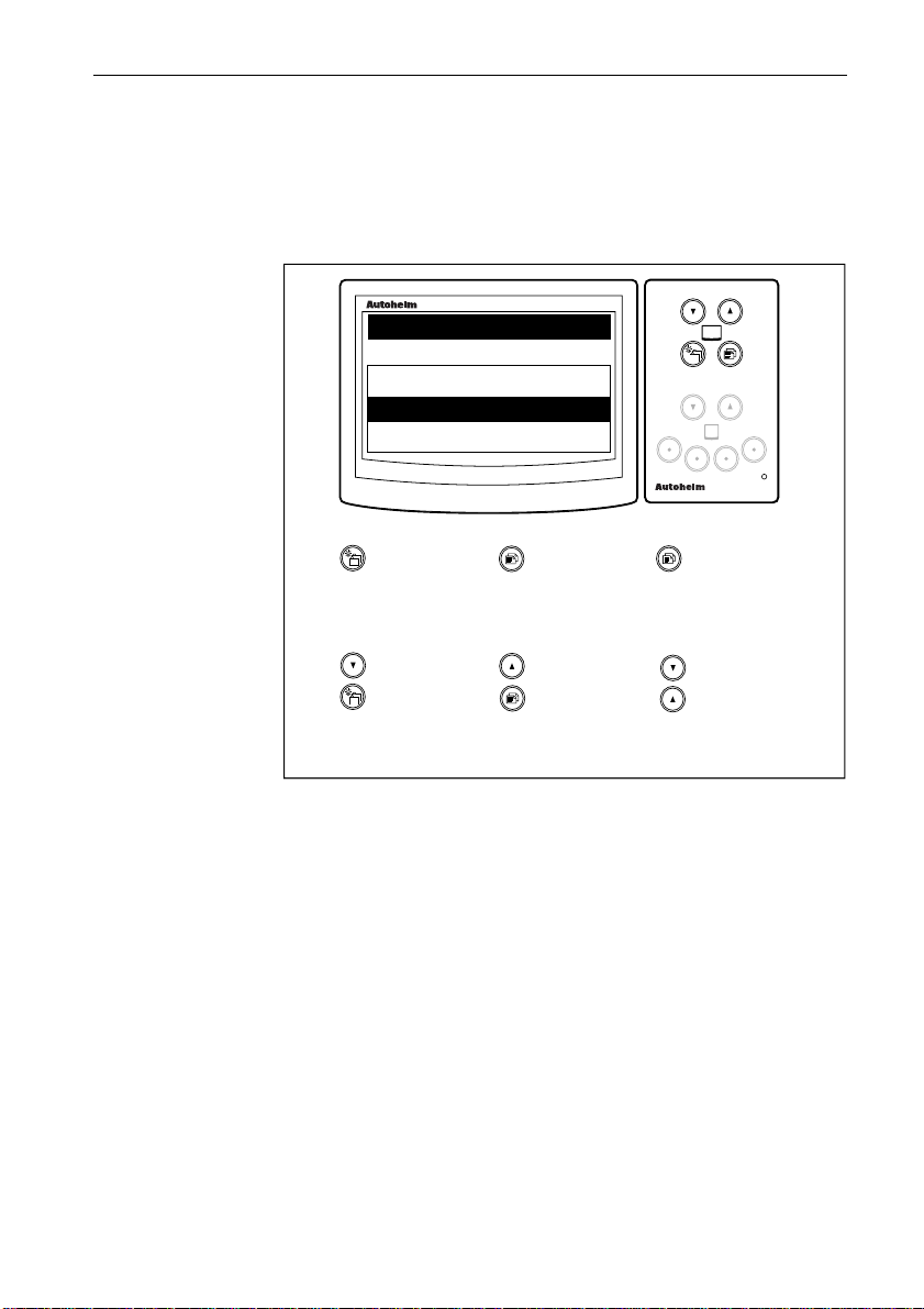
Use the middle two keys to cycle
chapters and pages and select another
Maxiview. The key changes the key
functions from chapter/page to select.
Quick Reference Guide
maxiview
remote
remoteremote
12.5 FT
120oM
masterview
MAXIVIEW
REMOTE
masterview
MAXIVIEW
REMOTE
ST80 Maxiview Operation and Setup8
Page 12

ST80 Maxiview Operation and Setup
CHAPTERS PAGES
9
SPEED
CHAPTER
DEPTH
CHAPTER
WIND
CHAPTER
HEADING
CHAPTER
NAVIGATE
CHAPTER
TIMERS
CHAPTER
MULTILINE
CHAPTER
NP
SPEED
DEPTH
APPARENT
WIND
SPEED
HEADING
POSITION
RACE
TIMER
UP TO 8
USER DEFINED
PAGES
SPEED
OVER
GROUND
MINIMUM
DEPTH
APPARENT
WIND
ANGLE
STEER COURSE
COG
BTW
NP
NP
VMG
TO
WIND
DEPTH
OFFSET
SAILING
TRUE WIND
SPEED
OVER
GROUND
CROSS
TRACK
ERROR
LOG &
TRIP
NP
NP
SAILING
TRUE WIND
ANGLE
NP NP NP
BEARING
TO
WAYPOINT
VMG
TO
WAYPOINT
AVERAGE
SPEED
MAGNETIC
TRUE WIND
ANGLE
TACK
COURSE
WAYPOINT
DATA
MAXIMUM
SPEED
NP
DATE
TIME
TIDE
NP: Page not available if the power option has been selected
Maximum Speed & Minimum Depth
The maximum speed and minimum depth displays can be reset by pressing and holding
the & keys together for 4 seconds - the display flashes during this period.
Page 13

Chapter 2: Operation
2.1 General
The Maxiview operates around a chapter and page principle –
chapters are independent sections: speed, depth, wind, etc., and
pages data related to that chapter.
When the Maxiview is powered up for the first time, the unit
defaults to the SAIL configuration, unless a POWER configuration
is received via SeaTalk (refer to the Masterview setup chapter).
Operating the Maxiview using the Remote Keypad
To operate the Maxiview using the Remote Keypad, you must first
carry out the setup procedures covered in the ST80 Remote Keypad
setup chapter.
Note: SeaTalk data must be available for a chapter to function. For
example, if speed data is lost for 8 seconds, the speed chapter is
replaced by a warning screen.
Keypad Beeps
• The keypad beeps once every time a key is pressed.
• An incorrect key sequence causes the Maxiview to beep a further 2
times.
ST80 Maxiview Operation and Setup10
Gaining Control of the Maxiview
• In order to make changes to the Maxiview displays, you must gain
control of the required Maxiview.
• Control is confirmed by the display changing to reverse video.
Page 14

ST80 Maxiview Operation and Setup
2.2 Speed Chapter
Boat Speed Page
This page displays your actual boat speed.
11
maxiview
SPEED KNOTS
10.5
remote
Press momentarily
to advance to the
next chapter.
Press momentarily
to advance to the
next page.
Press for 1
second to return
to the previous
page.
D2469-1
• The speed units are the units currently on SeaTalk: KNOTS, MPH
or KM/H.
• Trend indicators ▲ or ▼ are displayed if the boat speed is generally
decreasing or increasing at a rate greater than the value set in setup.
• The indicators are, by default, turned off.
Page 15

ST80 Maxiview Operation and Setup12
Speed Over Ground (SOG) Page
This page displays your current speed over the ground from GPS.
maxiview
SOG
KNOTS
6.5
remote
Press momentarily
to advance to the
next chapter.
Press momentarily
to advance to the
next page.
Press for 1
second to return
to the previous
page.
D2470-1
• The speed units can be: KNOTS, MPH or KM/H.
Velocity Made Good (VMG) to Wind Page
VMG to wind displays your boat speed through the water in the
direction of true wind.
maxiview
VMG WIND
KNOTS
6.3
remote
Press momentarily
to advance to the
next chapter.
Press momentarily
to advance to the
next page.
• The units are those currently on SeaTalk: KNOTS, MPH or KM/H.
• Trend indicators ▲ or ▼ are displayed if the VMG is generally
decreasing or increasing at a rate greater than the value set during
calibration. The indicators are, by default, turned off.
• This page is not available if the unit is operating in POWER mode.
Press for 1
second to return
to the previous
page.
D2471-1
Page 16

ST80 Maxiview Operation and Setup
Log/Trip Page
The Log/Trip page displays the total distance logged and a list of
trips and their current status.
LOG/ TRIP
LOG
TRIP 1 OFF
TRIP 2 OFF
TRIP 3 ON
TRIP 4 OFF
TRIP 5 ON
13
maxiview
NM
10000.5
1000.5
1102.5
20.20
0.00
50.85
remote
Press momentarily
to advance to the
next chapter.
Press momentarily
to advance to the
next page.
Press for 1
second to return
to the previous
page.
• The units are those currently on SeaTalk: NM, SM or KM.
• The trip list and the log cannot be controlled from the Maxiview.
Please refer to the Masterview handbook for trip control
information.
D2472-1
Page 17

ST80 Maxiview Operation and Setup14
Average Speed
This page displays the average boat speed for your current journey.
maxiview
SPEED
AVG
KNOTS
8.0
remote
Press momentarily
to advance to the
next chapter.
Press momentarily
to advance to the
next page.
Press for 1
second to return
to the previous
page.
D2473-1
• The units are those currently on SeaTalk: KNOTS, MPH or KM/H.
• The word STOPPED is displayed if this feature is not running.
• The maximum averaging period is 24 hours.
Maximum Speed Page
This displays the maximum speed achieved during the current voyage.
maxiview
SPEED
MAX
KNOTS
8.5
remote
Press
momentarily
to advance
to the next
chapter.
Press
momentarily
to advance
to the next
page.
• The units are those currently on SeaTalk: KNOTS, MPH or KM/H.
• The display flashes for 4 seconds when the maximum speed is reset.
Press for 1
second to
return to
the
previous
page.
Press and
hold these
keys for 4
seconds to
reset the
maximum
speed.
D2474-1
Page 18

ST80 Maxiview Operation and Setup
2.3 Depth Chapter
Depth Page
The depth page displays the current depth available on SeaTalk.
15
maxiview
DEPTH FEET
32.5
remote
Press momentarily
to advance to the
next chapter.
Press momentarily
to advance to the
next page.
Press for 1
second to return
to the previous
page.
D2475-1
• The displayed units are those currently on SeaTalk: FEET,
FATHOMS or METRES.
• Trend indicators ▲ or ▼ are displayed if the trend is generally
towards decreasing or increasing depth at a rate greater than that set
during calibration.
• The indicators are, by default, turned off.
• If the depth echo is lost the last valid echo is displayed together with
the caption “LAST ECHO”. Also, the current units are abbreviated
to FT, FA or M.
Page 19

Minimum Depth Page
DEPTH
MIN
9.2
ST80 Maxiview Operation and Setup16
maxiview
FT
remote
Press
momentarily
to advance
to the next
chapter.
Press
momentarily
to advance
to the next
page.
Press for 1
second to
return to
the
previous
page.
Press and
hold these
keys for 4
seconds to
reset the
minimum
depth.
D2476-1
• The units are: FEET, FATHOMS or METRES.
• The time of the last echo is displayed in the 12 or 24 hour clock. This
field is deactivated if time is not available.
• The display flashes for 4 seconds when the minimum depth is reset.
Depth Offset Page
This page displays the depth transducer offset.
maxiview
DEPTH
OFFSET
FT
-2.0
KEEL
remote
Press momentarily
to advance to the
next chapter.
Press momentarily
to advance to the
next page.
Press for 1
second to return
to the previous
page.
• The units are FEET (FT), FATHOMS (FA) or METRES (M).
• The offset can be keel, transducer or waterline – no adjustment is
possible from the Maxiview.
D2477-1
Page 20

ST80 Maxiview Operation and Setup
2.4 Wind Chapter
Apparent Wind Speed page
maxiview
WIND
APP
KNOTS
20.0
17
remote
Press momentarily
to advance to the
next chapter.
Press momentarily
to advance to the
next page.
Press for 1
second to return
to the previous
page.
• The units can be : KNOTS or M/SEC.
Apparent Wind Angle Page
maxiview
WIND
APP
s STBD
090
Press momentarily
to advance to the
next chapter.
Press momentarily
to advance to the
next page.
• The direction indicator is displayed as PORT or STBD.
Press for 1
second to return
to the previous
page.
D2478-1
remote
D2479-1
Page 21

ST80 Maxiview Operation and Setup18
True Wind Speed Page (Relative to the Vessel)
maxiview
KNOTS
8.5
remote
Press momentarily
to advance to the
next chapter.
Press momentarily
to advance to the
next page.
Press for 1
second to return
to the previous
page.
• The true wind units can be either: KNOTS or M/S.
• This page is not available in POWER mode.
True Wind Angle (Relative to the Vessel)
maxiview
PORT
096
Press momentarily
to advance to the
next chapter.
Press momentarily
to advance to the
next page.
• The direction indicator is displayed as PORT or STBD.
• This page is not available in POWER mode.
Press for 1
second to return
to the previous
page.
D2480-1
remote
D2481-1
Page 22

ST80 Maxiview Operation and Setup
True Wind Angle (Referenced to the Compass)
19
maxiview
WNW
296
Press momentarily
to advance to the
next chapter.
M
Press momentarily
to advance to the
next page.
remote
Press for 1
second to return
to the previous
page.
• This page is not available in POWER mode.
• The angle can be either true (T) or magnetic (M).
• An inter-cardinal/cardinal representation is also shown at the top
right of the screen (e.g., WNW).
2.5 Heading Chapter
Heading Page
maxiview
HEADING
TRUE
126
D2482-1
Press momentarily
to advance to the
next chapter.
Press momentarily
to advance to the
next page.
• The heading can be true or magnetic.
remote
Press for 1
second to return
to the previous
page.
D2483-1
Page 23

ST80 Maxiview Operation and Setup20
Steering Page
The steering page displays the current compass heading (unlocked
mode) or the locked compass heading (locked mode).
Note: For a detailed description of locked mode, please refer to a
Masterview handbook.
maxiview
STEER
UNLOCKED
136
Press momentarily
to advance to the
next chapter.
T
Press momentarily
to advance to the
next page.
remote
Press for 1
second to return
to the previous
page.
• The displayed value can be true (T) or magnetic (M).
Course Over Ground (COG) Page
This page displays your true or magnetic course over the ground.
maxiview
COG
TRUE
236
remote
Press momentarily
to advance to the
next chapter.
Press momentarily
to advance to the
next page.
• Whether the course is true or magnetic is dependant on the units
currently on SeaTalk.
Press for 1
second to return
to the previous
page.
D2484-1
D2485-1
Page 24

ST80 Maxiview Operation and Setup
Bearing to Waypoint (BTW) Page
This page shows the magnetic or true bearing to a target waypoint.
BTW
276
21
maxiview
TRUE
remote
Press momentarily
to advance to the
next chapter.
Press momentarily
to advance to the
next page.
Press for 1
second to return
to the previous
page.
Tack Course Page
This page displays the course for the next (opposite) tack in degrees
true or magnetic.
maxiview
TRUE
326
remote
Press momentarily
to advance to the
next chapter.
Press momentarily
to advance to the
next page.
• This page is not available in POWER mode.
• The tack course is based on sailing true wind.
Press for 1
second to return
to the previous
page.
D2486-1
D2487-1
Page 25

2.6 Navigate Chapter
Position Page
POSITION
050 49.10
002 49.10
ST80 Maxiview Operation and Setup22
maxiview
N-E
remote
Press momentarily
to advance to the
next chapter.
Press momentarily
to advance to the
next page.
Press for 1
second to return
to the previous
page.
• If position data is not available the fields are filled with dashes.
Course Over Ground (COG) & Bearing to
Waypoint (BTW)
This page displays both your course over ground and the bearing to a
target waypoint in degrees true or magnetic.
maxiview
COG
TRUE
BTW
TRUE
Press momentarily
to advance to the
next chapter.
240
272
Press momentarily
to advance to the
next page.
remote
Press for 1
second to return
to the previous
page.
D2488-1
D2489-1
Page 26

ST80 Maxiview Operation and Setup
Cross Track Error
The cross track error (XTE) page shows how far, in nautical miles
(NM), statute miles (SM) or kilometres (KM), your vessel is from a
planned route.
maxiview
XTE
NM
0.34
23
remote
Press momentarily
to advance to the
next chapter.
Press momentarily
to advance to the
next page.
Press for 1
second to return
to the previous
page.
• The arrows indicate the direction to steer to correct any error.
Velocity Made Good (VMG) to Waypoint Page
This page displays your boat speed over the ground in the direction
of a target waypoint.
maxiview
KNOTS
13.5
remote
Press momentarily
to advance to the
next chapter.
Press momentarily
to advance to the
next page.
• Trend indicators ▲ or ▼ are displayed if the trend is generally
towards decreasing or increasing VMG. The indicators are, by
default, turned off.
Press for 1
second to return
to the previous
page.
D2490-1
D2491-1
Page 27
ST80 Maxiview Operation and Setup24
Waypoint Data Page
This page displays any cross track error, the distance to a target
waypoint (DTW), estimated time to arrival (ETA) and waypoint
number.
maxiview
010
1.2
DTW
ETA
Press momentarily
to advance to the
next chapter.
25.5 NM
01: 30: 15
Press momentarily
to advance to the
next page.
remote
Press for 1
second to return
to the previous
page.
D2492-1
• The arrows to the right or left of the XTE value indicate the direction
to steer.
• The distance to waypoint can be nautical miles (NM), statute miles
(SM) or kilometres (KM).
• The ETA value is the time to go in hours, minutes and seconds.
Page 28
ST80 Maxiview Operation and Setup
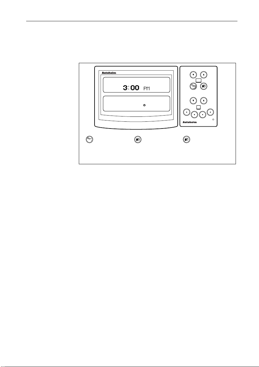
Date/Time/Tide Page
This page displays the speed and direction of the tide and the local
time.
25
maxiview
12 JUNE 95
TIDE
6.5 KNOTS
130 TRUE
remote
Press momentarily
to advance to the
next chapter.
Press momentarily
to advance to the
next page.
Press for 1
second to return
to the previous
page.
D2493-1
• Local time is a calculation based on a global offset . Please refer to
the Masterview handbook for details.
• The time and date format is taken from data on SeaTalk.
• Tide and speed units can be KNOTS, MPH or KM/H.
• The tide can be magnetic or true.
Page 29

ST80 Maxiview Operation and Setup26
2.7 Race Timer Chapter
Race Start Page
This page duplicates race timer data from a Masterview instrument.
There are just two operating modes: STOPPED and COUNTING
DOWN/UP.
maxiview
RACE START
10:00
remote
Press momentarily
to advance to the
next chapter.
• The display shows minutes and seconds only.
• When the timer reaches 00:00 the timer enters race mode (see
below).
D2494-1
maxiview
RACE TIME
01:30
remote
Press momentarily
to advance to the
next chapter.
• In race mode the timer shows the elapsed time in minutes and
seconds up to 1 hour, and hours and minutes thereafter (seconds are
displayed in small characters).
D2495-1
Page 30

ST80 Maxiview Operation and Setup
2.8 Multi-Line
Multi-line chapters consist of up to 8 pages of user-defined pages.
DEPTH
7.2
SPEED
HEADING
maxiview
FEET
6.7 KTS
120 M
27
2
remote
Press
momentarily
to advance
to the next
chapter.
Press
momentarily
to advance
to the next
page.
Press for 1
second to
return to
the
previous
page.
Press these
keys
together
momentarily
to enter
help/edit
mode.
D2496-1
• The multi-line page number is shown at the top-right of the screen.
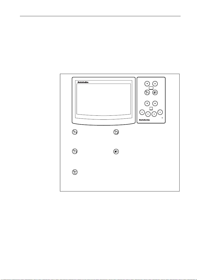
Help/Setup Page
maxiview
HELP: PRESS ANY KEY...
CHAP+
CHAP+
PAGE
CHAP
PAGE+
CHAP+ PAGE
+
Advance to
Multiline
setup page.
• Multi-line setup/help is only available if “EDIT ALL” or “EDIT
PAGES” has been selected in setup.
• When you exit Multi-line edit, the display returns to the previous
Multi-line page.
• The display returns to the previous Multi-line page after 8 seconds
of keypad inactivity.
INSERT PAGE
DELETE PAGE
NEXT DATA
PREV. DATA
NEXT LINE
1- 2 LINE
Advance to
Multiline
setup page.
EXIT
remote
Press these keys
together momentarily
to exit multiline setup.
D2497-1
Page 31

Multi-line Setup
DEPTH
25.2
SPEED
HEADING
ST80 Maxiview Operation and Setup28
maxiview
FEET
6.5 KTS
120 M
2
remote
Press to change
the current
option to the
previous option.
Press to change
the current
option to next
option.
Press these keys
together
momentarily to
switch between
1 and 2 line
entries.
Press and hold
these keys for 4
seconds to delete
the current
multiline page.
Press these keys
together
momentarily to
exit setup and
return to the
current multiline
page.
Press and hold
these keys for 4
seconds to insert
new multiline page
before current.
Press these keys
together
momentarily to
select next line.
D2498-1
• The currently selected line appears in reverse video.
• The current page appears in the top right hand corner of the display.
• The display flashes for 4 seconds when a page is deleted. After 4
seconds, “PAGE DELETED” is displayed along with the deleted
page number.
• The next page is displayed when a page is deleted.
• The display flashes for 4 seconds when a page is inserted. After 4
seconds, “PAGE INSERTED” is displayed.
• A single line at the bottom of the display cannot be changed for a
two-line entry.
• New pages always consist of 4 lines. Each line displays speed data
until it is changed.
• Page numbers are automatically renumbered when pages are
inserted or deleted.
Page 32

ST80 Maxiview Operation and Setup
List of Multi-line Selections
The lines of data that can be selected are as follows:
Line Data Line Data
1 Speed 17 Steer
2 Speed over ground 18 Course over ground
3 Velocity made good to wind 19 Tack course
4 Velocity made good over ground 20 Vessel latitude
5 Log 21 Vessel longitude
6 Trip 1 22 Cross track error
7 Average speed 23 Velocity made good to wayp’t
8 Depth 24 Waypoint number
9 Water temperature 25 Distance to waypoint
10 Apparent wind speed 26 Bearing to waypoint
11 Apparent wind angle 27 Estimated time to arrival
12 True wind speed 28 Date
13 True wind angle relative 29 Time
14 True wind angle absolute 30 Tide set
15 Beaufort 31 Tide drift
16 Heading
29
Page 33

ST80 Maxiview Operation and Setup30
Multi-line Factory Defaults
The factory defaults for the Multi-line pages are:
Page Line Content
1 1 Speed
2 Average speed
3 Speed over ground
4 Velocity made good to waypoint
2 1 Depth
2 Water temperature
3 1 Heading
2 Steer
3 Course over ground
4 Bearing to waypoint
4 1 True wind angle
2 True wind speed
3 Tack course
4 Beaufort
5 1 Waypoint number
2 Cross track error
3 Distance to waypoint
4 Estimated time to arrival
6 1 Speed
2 Depth
7 1 Speed
2 Depth
3 Apparent wind angle
4 Apparent wind speed
8 1 Course over ground
2 Speed over ground
3 Tide set
4 Tide drift
Page 34
ST80 Maxiview Operation and Setup
2.9 Illumination
There are two modes: local and system. Each of these modes has
four possible settings: level 3 (brightest), level 2, level 1 and off.
Local illumination is used to adjust the lighting of individual
display heads — adjustments will not affect other display heads.
System illumination controls the lighting of all display heads in
system mode.
31
maxiview
LOCAL LAMPS
3
remote
Press this key for 1
second from any
page to open the
illumination display.
In local illumination,
press this key for 5
second to change to
system illumination.
In system illumination,
press this key for 1
second to return to
local illumination.
Once the local or system
illumination display is active,
press this key momentarily to
adjust the current setting.
Press this key for 1
second to reset the
contrast.
D2540-1
• Local mode remains active until the power supply is switched off, or
the mode is changed to system.
• If the LCD illumination is off when adjustment mode is entered, the
unit automatically defaults to level 3.
• If the LCD is already illuminated the current level is displayed upon
entry into adjustment mode.
• The display returns to normal operation if there are no further key
presses within 8 seconds.
Page 35

ST80 Maxiview Operation and Setup32
Resetting the Contrast
The display contrast can, during local or system illumination
adjustment, be reset to the factory default by pressing the page key
for 1 second.
2.10 Data Lost
If a chapter that is dependent on a given quantity, e.g., speed, wind,
depth, and this data is lost for more than 8 seconds, a warning screen
is displayed until the data is restored.
maxiview
WARNING
SPEED CHAPTER
NOT AVAILABLE
DATA LOST
remote
D2560-1
2.11 Man Overboard and Alarms
Man Overboard
Man overboard displays are triggered when a man overboard
condition exists on SeaTalk. These displays replace the current
display until the condition no longer exists.
Dead Reckoned MOB
maxiview
MOB
078
DR
TRUE
08:30
1.2 NM
remote
Press this key momentarily
to display Lat/Lon
information if available.
D2542-1
Page 36

ST80 Maxiview Operation and Setup
• The dead reckoned screen is displayed providing data is available.
• Fields where data is not available appear as dashes.
• The elapsed time is displayed in minutes and seconds.
• The displayed bearing and range is to the man in the water.
Lat/Lon MOB
33
maxiview
MOB
078
POS
08:30
TRUE
1.2 NM
remote
Press this key momentarily
to display dead reckoned
information if available.
• This screen is displayed upon entry to MOB if dead reckoned
information is not available.
• Time data may not be shown if the man-overboard data is not
sourced from ST80.
Incomplete MOB Data
If there is insufficient data to provide range, bearing and elapsed
time, the following screen is displayed during an MOB condition.
maxiview
MAN
D2543-1
OVER
BOARD
remote
D2544-1
Page 37

ST80 Maxiview Operation and Setup34
MOB Audible Alarm
During an MOB condition, an audible alarm beeps 3 times every
thirty seconds.
Alarms
The Maxiview can be set to respond to all the alarms in the
following table or, alternatively, only those identified as specific.
Alarm Pop-Up Displayed Response
Shallow depth SHALLOW WATER All
Deep depth DEEP WATER All
Anchor ANCHOR ALARM All
True wind high speed TRUE WIND SPEED HIGH All
True wind low speed TRUE WIND SPEED LOW All
True wind high angle TRUE WIND ANGLE HIGH All
True wind low angle TRUE WIND ANGLE LOW All
Apparent wind high speed APPARENT WIND SPEED HIGH All
Apparent wind low speed APPARENT WIND SPEED LOW All
Apparent wind high angle APPARENT WIND ANGLE HIGH All
Apparent wind low angle APPARENT WIND LOW ANGLE A ll
Manual off-course OFF COURSE All
ST80 full watch WATCH PERIOD EXPIRED Specific
The following display is activated when an alarm is received. This
display flashes continuously until silenced/turned off or the alarm
description page is selected.
Press either key
momentarily to display
the alarm title pop-up or
the alarm description
page.
maxiview
remote
When the alarm title pop-up
is displayed, press either
of these keys to silence or
turn off the alarm.
D2541-1
Page 38

ST80 Maxiview Operation and Setup
The following table lists the alarm status once a silence/turn off
key- sequence is performed.
Alarm Silenced Turned Off
Shallow depth Yes No
Deep depth No Yes
Anchor Yes No
True wind high speed No Yes
True wind low speed No Yes
True wind high angle No Yes
True wind low angle No Yes
Apparent wind high speed No Yes
Apparent wind low speed No Yes
Apparent wind high angle No Yes
Apparent wind low angle No Yes
Manual off-course Yes No
Full ST80 watch Yes No
• If an alarm is currently active and an alarm of greater importance is
received, the current alarm is replaced with the new alarm.
• Replaced alarms are not stored by the Maxiview. However, the
alarm remains on SeaTalk and, if the condition still exists once the
current alarm has cleared, will be reinstated.
• Silenced alarms will repeat after 30 seconds if the condition persists.
35
Audible Alarms
There are basically two types of audible alarm: high priority and low
priority.
High priority alarms beep continuously while low priority alarms
consist of three beeps followed by a 5 second break.
• High priority alarms will always override low priority alarms.
• Once a high priority alarm has cleared, the previous alarm, if it is
still current, will be reactivated.
Page 39

36 ST80 Maxiview Operation & Setup
Chapter 3: Setup
This chapter describes how to set and adjust features in the setup
menu. These include display formats, response levels for controlling
the frequency of screen updates and the thresholds for trend
indicators.
3.1 Entering Setup
maxiview
DEPTH f FEET
36.5
remote
Press and hold these keys
together for 2 seconds to
display the user set-up screen.
maxiview
SET- UP
PRESS " PAGE" TO
CONTINUE...
remote
Press this key
momentarily to advance
to user setup.
D2499-1
• The Maxiview returns to normal operation after 4 seconds of keypad
inactivity.
• “SET-UP OFF” replaces the above screen if user setup has been
turned off in dealer setup.
• Setup can be entered from any normal operating display.
Page 40

ST80 Maxiview Operation & Setup
Speed Chapter
The following screen is displayed for 2 seconds when entering speed
setup. The key sequences shown are only available during this
period.
37
maxiview
SPEED
SET-UP
CHAP 1S FOR
INSTRUMENT CHAPTER
remote
Press this key to
advance to the next
chapter.
Press this key for 1
second to return to the
instrument chapter.
D2500-1
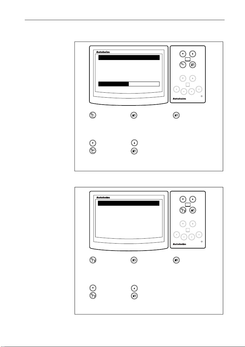
Response Pages
Response is used to control the speed at which screens are updated.
The response range is from 0 to 15. A high number results in rapid
changes of the displayed data while a low number gives a slow but
smooth update.
Page 41

38 ST80 Maxiview Operation & Setup
There are two response pages: speed and VMG to wind. Speed
response covers boat speed, speed over ground, velocity made good
to waypoint and velocity made good over ground to waypoint.
maxiview
SET-UP
SPEED
KNOTS
16.5
RESPONSE
S
07
F
remote
maxiview
SET-UP
VMG WIND
KNOTS
5.0
RESPONSE
S
Press this key
momentarily to
advance to the
next chapter.
Press these
keys together
momentarily to
decrease value
by 1.
• The current boat speed/VMG to wind is always displayed.
• The current response level is shown below the adjustment bar.
• Response applies only to the unit on which it is adjusted – it is not a
global change.
10
F
Press this key
momentarily to
advance to the
next page.
Press these
keys together
momentarily to
increase value
by 1.
Press this key
for 1 second to
return to the
previous page.
D2501-1
Trend Indicator Thresholds
The trend arrows (▲ or ▼) indicate the whether the general trend is
towards a higher or lower boat speed, SOG or VMG to wind. The
trend, whether its higher or lower, is determined by the threshold
setting.
Page 42

ST80 Maxiview Operation & Setup
maxiview
SET-UP
BOAT SPEED TREND
THRESHOLD
0.80
KNOTS/ SEC
maxiview
SET-UP
SOG TREND
THRESHOLD
2.50
KNOTS/ SEC
maxiview
SET-UP
VMG
WIND
TREND
THRESHOLD
39
remote
0.80
KNOTS/ SEC
Press this key
momentarily to
advance to the
next chapter.
Press these
keys together
momentarily to
decrease value
by 0.01.
Press this key
momentarily to
advance to the
next page.
Press these
keys together
momentarily to
increase value
by 0.01.
• The threshold is displayed in units (e.g., knots) per second.
• The threshold setting applies to the unit on which it is adjusted only.
Press this key
for 1 second to
return to the
previous page.
Press these keys
together
momentarily to
switch the trend
arrows ON/OFF.
D2502-1
Page 43

40 ST80 Maxiview Operation & Setup
Display Format
The display format can be set to either 1 or 2 decimal places.
maxiview
SET-UP
BOAT SPEED
DISPLAY FORMAT
X.X
X.XX
✓
✗
remote
Press this key
momentarily to
advance to the
next chapter.
Press these
keys together
momentarily to
highlight X.X
format.
Press this key
momentarily to
advance to the
next page.
Press these
keys together
momentarily to
highlight X.XX
format.
Press this key
for 1 second to
return to the
previous page.
Press these keys
together
momentarily to
select format.
• Values are limited to 3 significant figures. Values over 9.99 with
X.XX selected will be rounded up and truncated, e.g., 10.0.
Depth Chapter
The following screen is displayed for 2 seconds when entering depth
setup. The key sequences shown are only available during this
period.
maxiview
DEPTH
SET-UP
CHAP 1S FOR
SPEED CHAPTER
remote
D2503-1
Press this key to
advance to the next
chapter.
Press this key for 1
second to return to the
main speed chapter.
D2504-1
Page 44
ST80 Maxiview Operation & Setup
Depth Response
DEPTH
41
maxiview
SET-UP
FEET
20.5
RESPONSE
S
Press this key
momentarily to
advance to the
next chapter.
Press these
keys together
momentarily to
decrease value
by 1.
07
Press this key
momentarily to
advance to the
next page.
Press these
keys together
momentarily to
increase value
by 1.
Trend Indicator Thresholds
maxiview
SET-UP
DEPTH TREND
THRESHOLD
2.0
FEET/ SEC
Press this key
momentarily to
advance to the
next chapter.
Press this key
momentarily to
advance to the
next page.
F
remote
Press this key
for 1 second to
return to the
previous page.
D2505-1
remote
Press this key
for 1 second to
return to the
previous page.
Press these
keys together
momentarily to
decrease value
by 0.1.
Press these
keys together
momentarily to
increase value
by 0.1.
D2506-1
Page 45

42 ST80 Maxiview Operation & Setup
Depth Display Format
maxiview
SET-UP
DEPTH SPEED
DISPLAY FORMAT
X
X.X
✓
✗
remote
Press this key
momentarily to
advance to the
next chapter.
Press these
keys together
momentarily to
highlight X
format.
Press this key
momentarily to
advance to the
next page.
Press these
keys together
momentarily to
highlight X.X
format.
Press this key
for 1 second to
return to the
previous page.
Press these keys
together
momentarily to
select format.
D2507-1
Wind Chapter
The following screen is displayed for 2 seconds when entering wind
setup. The key sequences shown are only available during this
period.
maxiview
WIND
SET-UP
CHAP 1S FOR
DEPTH CHAPTER
remote
Press this key to
advance to the next
chapter.
Press this key for 1
second to return to the
depth chapter.
D2508-1
Page 46

ST80 Maxiview Operation & Setup
Wind Speed Response
WIND SPEED
SET-UP
5.0
RESPONSE
43
maxiview
KNOTS
S
Press this key
momentarily to
advance to the
next chapter.
Press these
keys together
momentarily to
decrease value
by 1.
07
Wind Angle Response
SET-UP
WIND ANGLE
100 P
RESPONSE
S
07
F
Press this key
momentarily to
advance to the
next page.
Press these
keys together
momentarily to
increase value
by 1.
maxiview
F
remote
Press this key
for 1 second to
return to the
previous page.
D2509-1
remote
Press this key
momentarily to
advance to the
next chapter.
Press these
keys together
momentarily to
decrease value
by 1.
Press this key
momentarily to
advance to the
next page.
Press these
keys together
momentarily to
increase value
by 1.
Press this key
for 1 second to
return to the
previous page.
D2510-1
Page 47

44 ST80 Maxiview Operation & Setup
Display Format
maxiview
SET-UP
WIND SPEED
DISPLAY FORMAT
X
X.X
✓
✗
remote
Press this key
momentarily to
advance to the
next chapter.
Press these
keys together
momentarily to
highlight X
format.
Press this key
momentarily to
advance to the
next page.
Press these
keys together
momentarily to
highlight X.X
format.
Press this key
for 1 second to
return to the
previous page.
Press these keys
together
momentarily to
select format.
D2507-1
Multiline Chapter
The following screen is displayed for 2 seconds when entering
multiline setup. The key sequences shown are only available during
this period.
maxiview
MULTILINE
SET-UP
CHAP 1S FOR
WIND CHAPTER
remote
Press this key to
advance to the next
chapter.
Press this key for 1
second to return to the
wind chapter.
D2512-1
Page 48
ST80 Maxiview Operation & Setup
Editing Rights
The editing rights chapter allows you to control the level of multiline
page editing. The options are: edit all, edit pages and no editing.
SET-UP
MULTILINE
EDIT ALL
EDIT PAGES
NO EDITING
45
maxiview
✓
✗
✗
remote
Press this key
momentarily to
advance to the
next chapter.
Press these
keys together
momentarily to
highlight next
option.
Press this key
momentarily to
advance to the
next page.
Press these
keys together
momentarily to
highlight
previous option.
Press these keys
together
momentarily to
select option.
• Edit all allows you to edit chapters and pages. Edit pages allows
editing of the page contents only .
D2513-1
Page 49

46 ST80 Maxiview Operation & Setup
3.2 Instrument Setup
maxiview
INSTRUMENT
SET-UP
CHAP 1S FOR
MULTILINE CHAPTER
remote
Press this key to
advance to the next
chapter.
Press this key for 1
second to return to the
multiline chapter.
Transducers Page
This page lists all the transducers connected to SeaTalk.
maxiview
SET-UP
TRANSDUCERS
SPEED
DEPTH
WIND
Press this key
momentarily to
advance to the
next chapter.
Press these
keys together
momentarily to
scroll down list.
✓
✓
✓
Press this key
momentarily to
advance to the
next page.
Press these
keys together
momentarily to
scroll up list.
Press this key
for 1 second to
return to the
previous page.
D2514-1
remote
D2515-1
• The complete transducer list is: speed, depth, wind, compass, pilot
and GPS.
• Detected transducers are identified by a ✓. Transducers not detected
appear in name only.
Page 50

ST80 Maxiview Operation & Setup
Sail/Power/Custom Selection
This page allows you to select whether chapters are custom selections
or, alternatively, dictated by the sail or power boat settings.
SET-UP
SELECT TYPE
SYSTEM
CUSTOM
47
maxiview
✓
✗
remote
Press this key
momentarily to
advance to the
next chapter.
Press these
keys together
momentarily to
highlight
custom.
Press these
keys together to
select (tick) the
highlighted
option.
Press this key
for 1 second to
return to the
previous page.
Press these
keys together
momentarily to
highlight
system.
Press this key
momentarily to:
go to the
custom setup
page if CUSTOM
is selected or
the chapter title
control page if
SYSTEM is
selected.
D2516-1
• If a selection has not been previously made, the SYSTEM option is
automatically tagged and SAIL mode is selected as the default
chapter and page mode.
• CUSTOM mode does not affect and is not affected by system
settings.
Page 51

48 ST80 Maxiview Operation & Setup
Custom
This mode allows you to select any of the chapters from the
following list:
No. Chapter No. Chapter
1 Speed 5 Navigate
2 Depth 6 Timers
3 Wind 7 Multiline
4 Heading
maxiview
SET-UP
CHAPTERS
SPEED
DEPTH
WIND
✓
✗
✓
remote
Press this key
momentarily to
return to speed
calibration
chapter.
Press these
keys together
momentarily to
highlight the
next listed
chapter.
Press this key
for 1 second to
return to the
selection page.
Press these keys
together
momentarily to
highlight the
previous
chapter.
Press this key
momentarily to
advance to the
Title Page
control.
Press and hold
these keys
together
momentarily to
enter control
setup.
D2517-1
• Enabled chapters are identified by a ✓. A ✗ indicates that a chapter is
switched OFF or does not have any pages enabled.
• This chapter appears in name only if a chapter is active but
fundamental information is missing.
Page 52

ST80 Maxiview Operation & Setup
Contents Setup
In custom setup, contents setup is used to select or de-select pages
within the highlighted chapter.
maxiview
SET-UP
NAVIGATE CHAPTER
OFF
POSITION
COG/ SOG
49
✗
✓
✓
remote
Press these
keys together
momentarily to
highlight the
next page.
Press these keys
together
momentarily to
highlight the
previous page.
Press this key
momentarily to
return to the
chapter setup
page.
Press these keys
together
momentarily to
turn the
highlighted page
ON/OFF.
D2518-1
• At least one page must be selected. The last page in a chapter cannot
be deleted.
• All pages are de-selected if OFF (✓) is chosen.
• De-selecting OFF automatically reselects the previously active
pages.
Page 53

50 ST80 Maxiview Operation & Setup
Title Control
This is used to turn the chapter title pages, displayed for 2 seconds
upon entry to a chapter, ON or OFF.
maxiview
SET-UP
CHAPTER TITLE PAGES
ON
OFF
✓
✗
remote
Press this key
momentarily to
return to speed
calibration
chapter.
Press these
keys together
momentarily to
highlight ON.
Press this key
momentarily to
advance to the
variation setup.
Press these keys
together
momentarily to
highlight OFF.
Press this key for
1 second to return
to the
sail/power/custom
selection page.
Press these keys
together
momentary to
select the
highlighted
option.
D2519-1
Page 54

ST80 Maxiview Operation & Setup
Variation
This page is used to enter the local variation to the nearest whole
degree.
51
maxiview
SET-UP
VARIATION
003
WEST
remote
Press this key
momentarily to
return to speed
calibration
chapter.
Press these
keys together
momentarily to
change value by
1 degree West.
Press this key
momentarily to
advance to the
true/magnetic
heading setup.
Press these keys
together
momentarily to
change value by
1 degree East.
Press this key
for 1 second to
return to the title
control page.
D2520-1
• The maximum variation that can be entered is 30°.
• If dashes are currently displayed, the first combination key press will
change the display to “000”.
• Variation is transmitted on SeaTalk.
Page 55

52 ST80 Maxiview Operation & Setup
True/Magnetic Heading
The true/magnetic heading page is used to select one of four options:
local true, local magnetic, global true or global magnetic.
maxiview
SET-UP
HEADING DISPLAY
LOCAL TRUE
LOCAL MAGNETIC
GLOBAL TRUE
✗
✓
✗
remote
Press this key
momentarily to
return to speed
calibration
chapter.
Press these
keys together
momentarily to
highlight the
next option.
Press this key
momentarily to
advance to lamp
adjustment
offset.
Press these keys
together
momentarily to
highlight the
previous option.
Press this key
for 1 second to
return to the
variation page.
Press these keys
together
momentary to
select the
highlighted
option.
D2531-1
• Upon exiting setup, the local true and local magnetic settings prevent
any response to incoming true or magnetic data.
• If variation is not available, the local and global true options cannot
be selected.
Page 56

ST80 Maxiview Operation & Setup
Lamp Offset Adjustment
This feature allows you to adjust the brightness of individual
illumination levels to obtain the best setting for a particular location.
53
maxiview
SET-UP
LAMP ADJSUTMENT
LEVEL
2
MIN
Press this key
momentarily to
advance to
contrast
adjustment.
Press these
keys together
momentarily to
decrease value
by 1.
32
MAX
Press this key
for 1 second to
return to the
previous page.
Press these
keys together
momentarily to
increase value
by 1.
remote
Press these keys
together
momentarily to
cycle illumination
levels.
• Lamp adjustment is not available if the current setting is OFF.
• The adjustment range is from 1 to 100%.
• If the current mode is “local”, changes will not be transmitted on
SeaTalk. However, changes will occur if the mode is “global”.
D2532-1
Page 57

54 ST80 Maxiview Operation & Setup
Contrast Adjustment
maxiview
SET-UP
CONTRAST
ADJUSTMENT
MIN
Press this key
momentarily to
return to speed
setup.
Press these keys
together
momentarily to
decrease value by 1.
07
MAX
Press this key
momentarily to
advance to LCD
inversion control
page.
Press these keys
together
momentarily to
increase value by 1.
remote
Press this key
for 1 second
to return to
the previous
page.
D2533-1
Page 58
ST80 Maxiview Operation & Setup
LCD Inversion
LCD inversion allows you to change the display to:
• display black numbers and characters on a light background
• or display light numbers and characters on a black background
SET-UP
DISPLAY
NORMAL
REVERSE
55
maxiview
✓
✗
remote
Press this key
momentarily to
return to speed
setup.
Press these
keys together
momentarily to
highlight
reverse.
Press this key
momentarily to
advance to
alarm page
control.
Press these keys
together
momentarily to
highlight normal.
Press this key
for 1 second to
return to
contrast
adjustment.
Press these keys
together
momentary to
select the
highlighted option.
D2534-1
Page 59

56 ST80 Maxiview Operation & Setup
Alarm Control
This page is used to define whether all or just specific alarms will be
recognised by the Maxiview.
maxiview
SET-UP
ENABLED ALARMS
ALL
SPECIFIC
✓
✗
remote
Press this key
momentarily to
return to speed
setup.
Press these
keys together
momentarily to
highlight
specific.
Press this key
momentarily to
return to
transducers
page.
Press these keys
together
momentarily to
highlight all.
Press this key
for 1 second to
return to LCD
inversion.
Press these keys
together
momentary to
select the
highlighted
option.
D2535-1
Page 60

ST80 Maxiview Operation & Setup
3.3 Quitting User Setup
To quit setup, simply press the Chapter and Page keys together
momentarily to display the following screen.
SET-UP
EXIT
STORE SETTINGS
CANCEL CHANGES
57
maxiview
✗
✓
remote
If cancel is selected, press this key
momentarily to exit without saving.
If store is selected, press this key
momentarily to exit and store new
settings.
Press these
keys together
momentarily to
highlight cancel.
Press these keys
together
momentarily to
highlight store.
Press these keys
together
momentary to
select the
highlighted
option.
D2539-1
Page 61

58 ST80 Maxiview Operation & Setup
Chapter 4: CodeLock Security
4.1 What is CodeLock?
• CodeLock is a personal four digit security code designed to protect
your valuable equipment against theft.
• CodeLock does not have to be switched on, but it’s there if you
decide that you need it.
• When CodeLock is switched on, the code number is stored in the
memory of all CodeLock compatible equipment on the same bus.
• A CodeLocked piece of equipment, if stolen, cannot be used without
the correct code number.
• There are basically two types of CodeLock compatible equipment:
masters and slaves.
Master’s
• Are used to create and enter a CodeLock code number.
• The ST80 Masterview is a master display head.
Slave’s
• Cannot be used to create a CodeLock code number.
• Can be used to enter a code number to unlock a system.
• Receive and transmit your chosen code number only.
• ST80 slave’s consist of the: Analogue Wind, Analogue Close Hauled
Wind, Analogue Compass, Maxiview and the Analogue Multitrim.
Code creation is usually a once-off procedure carried out on a master
display head, which, ideally, is situated in a secure location below
deck. Once entered, the code is automatically sent to all CodeLock
compatible SeaTalk equipment without further intervention.
If you require a higher degree of security, perhaps all your
instruments are mounted in exposed locations, CodeLock can
demand that you enter your personal code every time the system is
switched on. In this configuration, the code can be entered into any
convenient master display head.
Page 62

ST80 Maxiview Operation & Setup
4.2 Analogue Display Heads
Automatic CodeLock Systems
In an automatically transmitted CodeLock system, the Maxiview
reads the code number and starts-up automatically without any user
input.
Manual CodeLock System
In a manually transmitted CodeLock system, the code number is
entered via the keypad of any master display head. This code is then
sent to all compatible equipment on the same SeaTalk bus. Once this
code has been received, the equipment operates in the normal way.
4.3 Enabling CodeLock
The CodeLock security feature can only be switched on from a
Masterview display head. Therefore, please refer to the Masterview
Operation & Setup manual for details.
59
Page 63

60 ST80 Maxiview Operation & Setup
Chapter 5: Problem Solving
5.1 Problem Solving
Display is blank
• Make sure that the power supply is connected.
• Check the fuse or circuit breaker.
• Make sure that the SeaTalk cables are not damaged.
• Check the contrast and illumination settings
• Faulty LCD module.
No exchange of information between SeaTalk instruments
• Make sure that the cables are attached securely.
• If the problem persists, disconnect your instruments one by one to
isolate the faulty unit.
Failure of a group of SeaTalk instruments
• Make sure that the SeaTalk connections to non-functioning
instruments are secure.
LCD shows “Code ON” when the power supply is
switched on
• The CodeLock anti-theft system is operational.
Poor character definition
• Adjust the contrast.
Page 64

ST80 Maxiview Operation & Setup
Chapter 6: EMC and Servicing Guidelines
6.1 Important information
All Autohelm equipment and accessories are designed to the best
industry standards for use in the leisure marine environment.
Their design and manufacture conforms to the appropriate
Electromagnetic Compatibility (EMC) standards, but good
installation is required to ensure that performance is not
compromised. Although every effort has been taken to ensure that
they will perform under all conditions, it is important to understand
what factors could affect the operation of the product.
6.2 Installation
To avoid the risk of operating problems, all Autohelm equipment and
cables connected to it should be;
• At least 1m (3 feet) from any equipment transmitting or cables
carrying radio signals, e.g., VHF radios, cables and antennas. In the
case of SSB radios, the distance should be increased to 2m (7ft).
• More than 2m (6ft) from the path of a radar beam. A radar beam can
normally be assumed to spread 20 degrees above and below the
radiating element.
• The equipment should be supplied from a different battery than the
one used for engine start. Voltage drops below 10V in the power
supply to our products can cause the equipment to reset. This will not
damage the equipment, but will cause the loss of some information
and can change the operating mode.
• Genuine Autohelm cables should be used at all times. Cutting and
rejoining these cables can compromise EMC performance and so
should be avoided unless doing so is detailed in the installation
manual.
• If a suppression ferrite is attached to a cable, this ferrite should not be
removed. If the ferrite has to be removed during installation it must
be reassembled in the same position.
61
Page 65

62 ST80 Maxiview Operation & Setup
6.3 Check Before Going to Sea
• Always check the installation before going to sea to make sure that it
is not affected by radio transmissions, engine starting etc.
• In some installations, it may not be possible to prevent the equipment
from being affected by external influences. In general this will not
damage the equipment but can lead to it resetting, or momentarily
may result in faulty operation.
6.4 Servicing and Safety
• Autohelm equipment should be serviced only by authorised
Autohelm service engineers. They will ensure that service
procedures and replacement parts used will not affect performance.
There are no user serviceable parts in any Autohelm product.
• Some products generate high voltages, and so never handle the
cables/connectors when power is being supplied to the equipment.
• Always report any EMC related problem to your nearest Autohelm
dealer. We will use any such information to improve our quality
standards.
Page 66

ST80 Maxiview Operation & Setup
Chapter 7: Specification
Dimensions: 110 x 114.5 x 18.25mm (4.33 x
Power supply: 10 to 16 V DC
Current consumption: 50 mA with illumination off
Operating temperature: -10 to +70°C (14°F to 158°F)
Illumination: 3 level illuminated dial and LCD
63
4.5 x 0.71in)
250mA with illumination full on
keypad permanently illuminated
Page 67

64 ST80 Maxiview Operation & Setup
Page 68

ST80 Maxiview Operation & Setup
Index
65
A
Alarm Control 56
Alarms 34
Apparent Wind Angle Page 17
Apparent Wind Speed page 17
Audible Alarms 35
Automatic CodeLock Systems 59
Average Speed 14
B
Bearing to Waypoint (BTW) Page 21
Boat Speed Page 11
C
CodeLock Security 58
Contents Setup 49
Contrast Adjustment 54
Course Over Ground (COG) & Bearing to
Waypoint (BT 22
Course Over Ground (COG) Page 20
Cross Track Error 23
Custom 48
D
Data Lost 32
Date/Time/Tide Page 25
Dead Reckoned MOB 32
Depth Chapter 15, 40
Depth Display Format 42
Depth Offset Page 16
Depth Page 15
Depth Response 41
Display Format 40, 44
E
G
Gaining Control of the Maxiview 10
H
Heading Chapter 19
Heading Page 19
Help/Setup Page 27
I
Illumination 31
Incomplete MOB Data 33
Instrument Setup 46
K
Keypad Beeps 10
L
Lamp Offset Adjustment 53
Lat/Lon MOB 33
LCD Inversion 55
List of Multi-line Selections 29
Log/Trip Page 13
M
Man Overboard 32
Man Overboard and Alarms 32
Manual CodeLock System 59
Maximum Speed Page 14
Minimum Depth Page 16
MOB Audible Alarm 34
Multi-Line 27
Multi-line Factory Defaults 30
Multi-line Setup 28
Multiline Chapter 44
Editing Rights 45
EMC and Servicing Guidelines 61
Enabling CodeLock 59
Entering Setup 36
N
Navigate Chapter 22
Page 69

66 ST80 Maxiview Operation & Setup
O
Operating the Maxiview using the Remote
Keypad 10
P
Problem Solving 60
Q
Quitting User Setup 57
R
Race Start Page 26
Race Timer Chapter 26
Resetting the Contrast 32
Response Pages 37
S
Sail/Power/Custom Selection 47
Servicing and Safety 62
Setup 36
Setup and Calibration 7, 36
Specification 63
Speed Chapter 11, 37
Speed Over Ground (SOG) Page 12
Steering Page 20
V
Variation 51
Velocity Made Good (VMG) to Waypoint
Page 23
Velocity Made Good (VMG) to Wind
Page 12
W
Waypoint Data Page 24
What is CodeLock? 58
Wind Angle Response 43
Wind Chapter 17, 42
Wind Speed Response 43
T
Tack Course Page 21
Title Control 50
Transducers Page 46
Trend Indicator Thresholds 38, 41
True Wind Angle (Referenced to the
Compass) 19
True Wind Angle (Relative to the Ves-
sel) 18
True Wind Speed Page (Relative to the
Vessel) 18
True/Magnetic Heading 52
81022–1
Page 70

Maxiview
Page 71

Raymarine Ltd.
Anchorage Park, Portsmouth,
P03 5TD, England.
Telephone: (44) (0) 2392 693611
Fax: (44) (0) 2392 694642
 Loading...