

Page 1

Distributed by
Any reference to Raytheon or
RTN in this manual should be
interpreted as Raymarine.
The names Raytheon and RTN
are owned by the
Raytheon Company.
Page 2
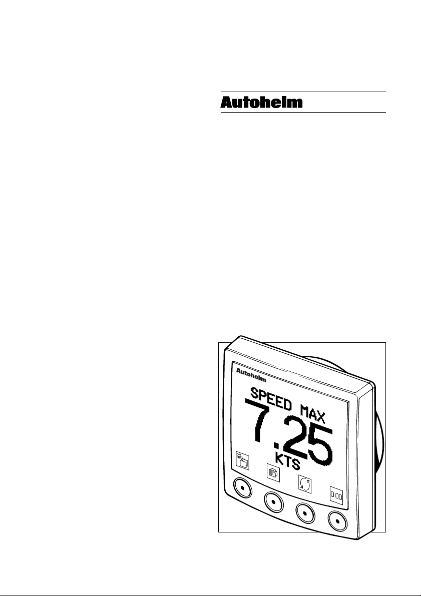
ST80
Mastervie w
User’ s Manual
masterview
.
Page 3

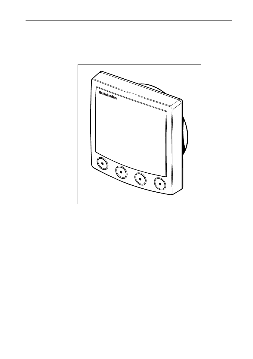
Masterview
Page 4

ST80 Masterview Operation and Setup
Package Contents
The ST80 Masterview package contains the following standard
items:
1. Masterview display head
2. Sun cover
3. Thumb nuts (2)
4. Fixing studs (2)
5. SeaTalk cable 0.38m (1.2ft)
6. Gasket
7. Cue card
8. Installation guide
9. Operation and Setup manual
10. Worldwide Service Centre booklet
11. Warranty card
Items missing ?
If any of the above items are missing, please contact your Autohelm
dealer or our Product Support Department. Please note that items
cannot be replaced without proof of purchase.
1
Registering this Product
Once you have checked that you have all of the listed components,
please take the time to complete the warranty document and return it
to your national distributor.
By returning this document you will receive prompt and expert
attention should you ever experience any difficulties with this
product. Also, your details will be added to our customer database so
that you automatically receive new product brochures as and when
they are released.
Page 5

2
ST80 Masterview Operation and Setup
Page 6

ST80 Masterview Operation and Setup
Contents
Chapter 1: Introduction ................................................................. 15
1.1 General ...............................................................................15
1.2 First-Time Power-Up . ... .... ... .... ... .... ... .... ... ... .... ... .... ... .... ... ...19
Points to remember... ........................................................... 19
Sail Mode............................................................................ 20
Power Mode ........................................................................ 21
1.3 Operation ............................................................................22
About this Chapter ............................................................... 22
Points to remember... ........................................................... 22
Speed Chapter ..................................................................... 22
Boat Speed Page .................................................................. 23
VMG to Wind Page ............................................................. 23
Trip/Log Page ..................................................................... 24
Trip Control Page ................................................................ 24
Average/Maximum Speed ................................................... 25
Average Speed .................................................................... 25
Maximum Speed ................................................................. 25
Speed Histogram ................................................................. 26
Sea Temperature ................................................................. 26
Depth Chapter ..................................................................... 27
Water Depth........................................................................ 27
What if the depth echo is lost? .............................................. 27
Depth Alarm Control ........................................................... 28
Editing the Depth Alarms .................................................... 28
Minimum Depth.................................................................. 29
Depth Offset ........................................................................ 29
Fish Finder .......................................................................... 30
Rate .................................................................................... 31
Sensitivity (SENS) and Gain ................................................ 31
Sensitivity ........................................................................... 31
Gain .................................................................................... 31
3
Page 7

4
ST80 Masterview Operation and Setup
Depth Histogram ................................................................. 32
Wind Chapter ...................................................................... 32
True Wind........................................................................... 33
Alarm Control ..................................................................... 33
Alarm Adjustment ............................................................... 33
Apparent Wind.................................................................... 34
Alarm Control ..................................................................... 34
Alarm Adjustment ............................................................... 34
Beaufort Scale ..................................................................... 35
True Wind Histogram (Speed and Angle) ............................. 35
Docking (Power and Custom Modes only)............................ 36
Apparent Wind Steer ........................................................... 36
Locked Mode ...................................................................... 36
Adjusting a Locked Apparent Wind Steer............................. 37
Autopilot Locked ................................................................ 37
Head in g C ha pt er ................................................................. 38
Heading and Course Over Ground........................................ 38
Tack Course ........................................................................ 39
Heading Steer ...................................................................... 40
Unlocked Mode................................................................... 40
Off Course Alarm ................................................................ 40
Locked Mode ...................................................................... 41
Adjusting a Locked Heading ................................................ 42
Heading Histogram (True and Course Over ground) ............. 42
Navigate Chapter................................................................. 43
Chapter Structure................................................................. 43
General Route and Waypoint Information ............................ 43
Entering Information ........................................................... 43
Waypoints........................................................................... 44
Entering New Waypoints..................................................... 44
Editing a Waypoint.............................................................. 45
Deleting a Waypoint............................................................ 46
What if the Waypoint is Used in Routes? .............................. 46
Page 8

ST80 Masterview Operation and Setup
Adding Event Marks............................................................ 47
Route Page .......................................................................... 47
Creating a Route .................................................................. 48
Deleting Waypoints from a Route ........................................ 50
What if I Decide that I Don’t Want to Delete the Waypoint?.. 50
Inserting a Waypoint in a Route ........................................... 51
Tracking to a Route Selected from the Route List.................. 51
Waypoint Advance.............................................................. 52
Deselecting a Route ............................................................. 52
Reversing the Direction of a Route ....................................... 52
Deleting a Route .................................................................. 52
Editing an Active Route....................................................... 52
Copying a Route to the ‘External Route’ Entry ..................... 53
Capturing Single Waypoints ................................................ 54
General Route Information .................................................. 54
Operation in Dead-Reckoned Mode ..................................... 54
Leg Information .................................................................. 55
Single Waypoint Page ......................................................... 55
Creating a Single Destination Waypoint ............................... 55
Selecting a Field to Edit ....................................................... 56
Tracking to a Single Waypoint ............................................. 57
Navigate Page ..................................................................... 57
Selecting Lines .................................................................... 58
Steering Page ...................................................................... 58
Cross Track Error ................................................................ 58
Course Deviation Indicator (CDI) ........................................ 59
Selecting Lines .................................................................... 60
What if a Target Waypoint does not Exist? ........................... 60
Position Page....................................................................... 60
SeaTalk Lat/Lon Data Available .......................................... 60
No SeaTalk Lat/Lon Data Available .................................... 61
Dead Reckoning (DR) Control ............................................. 61
Log Information .................................................................. 62
5
Page 9

6
ST80 Masterview Operation and Setup
General Page ....................................................................... 63
Tide .................................................................................... 63
Speed, Heading, Course Over Ground, Speed Over Ground .. 63
Speed and Heading .............................................................. 64
Speed Over Ground and Course Over Ground....................... 64
Local Time.......................................................................... 64
Fix Status ............................................................................ 65
Pilot Chapter ....................................................................... 65
Status Page .......................................................................... 66
Navigate Page ..................................................................... 66
Cross Track Error (XTE)...................................................... 67
Course Deviation Indicator (CDI) ........................................ 68
What if a waypoint is not selected? ....................................... 69
Auto Steer ........................................................................... 69
Vane Steer........................................................................... 70
General Page ....................................................................... 71
Tide .................................................................................... 71
Speed, Heading, COG and SOG ........................................... 71
Time ................................................................................... 72
Wind................................................................................... 72
Pop-Up Pilot Chapter........................................................... 73
Response............................................................................. 73
Rudder Gain ........................................................................ 74
Autopilot Status................................................................... 74
Course Change .................................................................... 74
Auto Tack ........................................................................... 75
Starboard Tack .................................................................... 75
Por t T a c k............................................................................. 75
Check Tack ......................................................................... 76
Track and Waypoint Advance.............................................. 76
Old Heading ........................................................................ 77
Old Wind Angle .................................................................. 77
Timers Chapter.................................................................... 78
Page 10

ST80 Masterview Operation and Setup
UTC Page ........................................................................... 78
Local Time Page ................................................................. 78
Modifying Local Time ........................................................ 79
Changing the Format ........................................................... 79
Local Time Alarm Control................................................... 79
Alarm Timer Page ............................................................... 80
Stopwatch Page ................................................................... 80
Running Mode .................................................................... 81
Stopwatch Reset .................................................................. 81
Lap Timer ........................................................................... 81
Resetting the Lap Timer....................................................... 82
Split Time ........................................................................... 82
Starting Another Lap Time .................................................. 82
Race Timer ......................................................................... 83
Countdown Mode................................................................ 83
Count-up Timer (Race Running Mode) ................................ 84
Race Reset .......................................................................... 84
Race Lap Mode ................................................................... 84
Lap Reset Mode .................................................................. 85
Split Race Time................................................................... 85
Environment Chapter .......................................................... 86
SeaTalk Voltage Histogram ................................................. 86
Sea Temperature Histogram................................................. 86
Nav Status Chapter .............................................................. 87
Data Source Page................................................................. 87
Fix Status Page .................................................................... 88
General Information Page .................................................... 88
Satellite Plot Page ................................................................ 89
Split Screen Mode ............................................................... 89
Multiline Chapter ................................................................ 90
Line Edit ............................................................................. 91
Chapter Edit ........................................................................ 92
Maxiview Remote Chapter .................................................. 93
7
Page 11

8
ST80 Masterview Operation and Setup
Maxiview Remote Control Page .......................................... 93
Illumination Selection and Adjustment................................. 94
Alarms ................................................................................ 95
Alarm Recognition .............................................................. 95
Recognised Autopilot Alarms .............................................. 96
High Priority Alarms ........................................................... 96
Identifying High Priority Audible Alarms............................. 96
Low Priority Alarms ............................................................ 97
Identifying Low Priority Audible Alarms ............................. 97
ST80 Watch Alarm.............................................................. 97
Timer Alarm ....................................................................... 98
Man Overboard (MOB) ....................................................... 98
Dead Reckoned MOB Data (Default) ................................... 98
Lat/Lon MOB Data ............................................................. 99
Waypoint 999...................................................................... 99
No Valid MOB Data .......................................................... 100
Audible MOB Alarm ......................................................... 100
Keypad Handling .............................................................. 100
Navigator Keypad ............................................................. 100
Remote Keypad................................................................. 100
Autopilot Keypad .............................................................. 100
Chapter 2: Setup.......................................................................... 101
2.1 About this Chapter ............................................................. 101
2.2 I ni ti al S ta rt -u p................................................................... 101
Points to remember... ......................................................... 101
2.3 Entry into User Setup ............................................... ... ....... 102
2.4 Speed .............. ............................................................. ..... 102
Boat Speed Response......................................................... 103
Adjusting Boat Speed Response ......................................... 103
VMG Wind Response........................................................ 104
Adjusting the Response...................................................... 104
Boat Speed Units ............................................................... 104
Distance Units ................................................................... 105
Page 12

ST80 Masterview Operation and Setup
Selecting Distance Units .................................................... 105
Speed Trend Indicators ...................................................... 105
Adjusting the Current Trend Threshold .............................. 105
VMG Trend Indicators ...................................................... 106
Speed Display Format........................................................ 106
Distance Display Format.................................................... 106
Speed Transducer Calibration ............................................ 106
Recording a Correction Factor Automatically..................... 107
Manually Recording and Entering a Calibration Factor ....... 109
Calibrating using Speed Over Ground (SOG) ..................... 110
2.5 Depth ......... ..................... .................... ..................... ......... 111
Switching the Transducer ON and OFF .............................. 111
Response Page................................................................... 111
Depth Units Page ............................................................... 111
Selecting Depth Units ........................................................ 112
Trend Indicators Page ........................................................ 112
Depth Display Format........................................................ 112
Depth Offset Page.............................................................. 112
Setting the Offset ............................................................... 114
2.6 Wind . . . . .. . .. . .. . .. . .. . .. . .. . .. . .. . .. . .. . .. . .. . .. . . .. . .. . .. . .. . .. . .. . .. . .. . .. . .. . .. . . 114
Wind Speed & Angle Response, Wind Speed Units & Display
Format .............................................................................. 114
Wind Speed Units.............................................................. 114
Wind Angle Offset Page .................................................... 114
Procedure .......................................................................... 115
2.7 Heading .. .... .... .... .... ..... .... .... .... .... .... ..... .... .... .... .... ..... .... ... 116
Heading Response ............................................................. 116
Response Adjustment ........................................................ 116
Compass Linearisation ...................................................... 117
Procedure .......................................................................... 117
Compass Offset Page ......................................................... 118
Adjusting the Offset........................................................... 119
Variation ........................................................................... 119
9
Page 13

10
ST80 Masterview Operation and Setup
Adjusting Variation ........................................................... 120
True/Magnetic Heading..................................................... 120
Changing the Heading ....................................................... 121
Heading Lock.................................................................... 121
2.8 Navigate ............................................................................ 122
XTE Response .................................................................. 122
Adjusting XTE Response................................................... 122
Waypoint Arrival Radius ................................................... 122
Adjusting the Radius.......................................................... 123
2.9 Pilot Setup ......................................................................... 123
Pilot Calibrate Entry Screen ............................................... 124
Vessel Type....................................................................... 124
Cal Lock ........................................................................... 125
Rudder Gain ...................................................................... 125
Rate Level ......................................................................... 126
Rudder Offset .................................................................... 127
Rudder Limit..................................................................... 127
Turn rate ........................................................................... 128
Default Speed .................................................................... 128
Off Course Limit ............................................................... 129
Trim Level ........................................................................ 129
Power Steer ....................................................................... 130
Drive Option ..................................................................... 131
Rudder Deadband (Damping) ............................................ 131
Variation ........................................................................... 132
Auto Adapt........................................................................ 132
Latitude ............................................................................ 133
Auto Release ..................................................................... 134
Wind Trim Time Constant ................................................. 134
Response........................................................................... 135
Unknown Cal Stage ........................................................... 135
Exiting Pilot Setup............................................................. 136
2.10 Timers Setup ...... ........ ....... ........ ........ ........ ........ ....... ....... 136
Page 14

ST80 Masterview Operation and Setup
Race Start.......................................................................... 136
Start Guns ......................................................................... 137
2.11 Environment . . .. .. .. .. . .. .. .. .. .. .. . .. .. .. .. .. . .. .. .. .. .. . .. .. .. .. .. . .. .. .. .. .. 137
Temperature Units............................................................. 137
Temperature Offset ........................................................... 138
Adjusting the Offset........................................................... 138
2.12 GPS Setup . .. .. ... .. .. ... .. ... .. .. ... .. .. ... .. .. ... .. ... .. .. ... .. .. ... .. ... .. .. .. 138
2.13 Round Repeater .. .. .. ... .. ... .. ... .. .. ... .. ... .. ... .. .. ... .. ... .. .. ... .. ... .. . 138
2.14 Multiline ................................ ....... ................ ....... ........... 139
2.15 Instrument Set-Up ......... ............ ........... ............ ............ ... 139
Chapter Title Control, Pilot Icon, Key Beep & MOB .......... 139
Chapter Title ..................................................................... 139
Pilot Status Icon Control .................................................... 140
Key Beep .......................................................................... 140
Display Mode .................................................................... 140
Alarm control .................................................................... 141
Lamp Offset ...................................................................... 141
Adjusting the Illumination Settings .................................... 142
Contrast ............................................................................ 142
Adjusting the Contrast ....................................................... 142
Navigator Keypad Linking ................................................ 143
Unlinking a Navigator Keypad........................................... 144
CodeLock ......................................................................... 144
Entering a New Code ......................................................... 145
Turning CodeLock Off ...................................................... 145
Transducer List ................................................................. 146
Boat Type ......................................................................... 146
Custom Chapter Selection.................................................. 147
Selecting Pages ................................................................. 147
2.16 Quitting User Setup ......................................................... 148
Chapter 3: CodeLock................................................................... 149
3.1 Introduction to CodeLock .... ........... .......... .......... .......... ..... 149
3.2 Masterview Display Heads . ... ... ... ... ... .. ... ... ... ... ... ... ... ... ... ... . 150
11
Page 15

12
ST80 Masterview Operation and Setup
Entering Your Chosen Code Number at Power-On ............. 150
Automatic CodeLock Transmission (Auto) ........................ 150
3.3 Analogue Display Heads ... .. ... ... ... .. ... ... ... .. ... ... ... .. ... ... ... .. ... 150
Automatic CodeLock Systems ........................................... 150
Manual CodeLock System ................................................. 150
Entering the Code Number................................................. 151
What if you enter the wrong number? ................................. 151
Chapter 4: Problem Solving ............................................... 152
4.1 Problem Solving ... ...... ...... ...... ...... ...... ..... ...... ...... ...... ...... .. 152
Display is blank - keypad not illuminated ........................... 152
Display is blank - keypad illuminated ................................. 152
No exchange of information between SeaTalk instruments . 152
Failure of a group of SeaTalk instruments ........................... 152
LCD shows “Code ON” when the power supply is
switched on ....................................................................... 152
Poor character definition .................................................... 152
Chapter 5: EMC and Servicing Guidelines .................................. 153
5.1 Important information ........................................................ 153
5.2 Installation........................................................................ 153
5.3 Check Before Going to Sea ..... ....... ...... ....... ...... ....... ...... .... 154
5.4 Servicing and Safety .......................................................... 154
Chapter 6: Specification ............................................................. 155
Index............................................................................................ 157
Page 16

ST80 Masterview Operation and Setup
ST80 System Overview
In todays world of marine electronics, we expect a more control at
our fingertips.
Navigation receivers give our position, electronic chart plotters
provide accurate chart information and autopilots keep us on track
on long passages. Performance monitoring instruments tell us
anything from speed over the water to the best course to steer to a
target waypoint.
The problem with conventional instrumentation is that the more
information you require the more space must be found to install the
additional displays. Lack of space often leads to compromise – you
can install the display where you can see it or where you can reach it
– but not always both! You may also want to have access to several
bits of information but the instrument to hand provides only one.
With ST80, all these limitations disappear. ST80 allows you to site
displays exactly where you want them and to display as much or as
little information as you require. Gone are the days when you wish
you could make a display vanish to make way for the information
you actually want — all you have to do is select the page of
information on the display nearest to you.
Although ST80 is an extremely sophisticated and comprehensive
electronics system, ease of use has not been compromised.
Operation of the primary displays revolves around a chapters and
pages concept — simply turn to the chapter containing the
information you require and “flick” the pages until the appropriate
page is displayed.
13
Page 17

14
ST80 Masterview Operation and Setup
Page 18
ST80 Masterview Operation and Setup 15
Chapter 1: Introduction
1.1 General
masterview
D2031-1
The Masterview is a powerful multi-function instrument capable of
displaying SeaTalk data in alphanumeric and graphic formats.
Operation revolves around a “Chapters and Pages” concept. There are
11 chapters, each with multiple pages containing information related
to the main chapter – a chapter is effectively an individual SeaTalk
instrument. This allows you to configure display heads for different
functions (for example, speed, depth, wind, position, heading).
The Masterview uses icons and screen prompts to guide you through
the various chapters, pages and special functions. This approach
makes the Masterview extremely easy to use.
When the Masterview is linked to an ST80 autopilot keypad, the
Masterview becomes a fully featured autopilot control centre.
In addition to the Autopilot keypad, the Navigator and Remote
keypads provide even more operating features. The Navigator allows
you to create, review and edit alphanumeric waypoint data. The
Remote allows you to operate the Masterview from a remote location.
Page 19
16 ST80 Masterview Operation and Setup
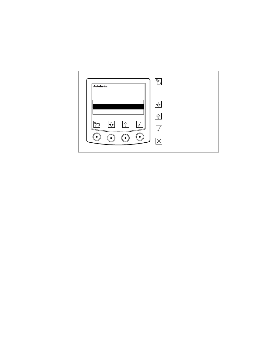
Masterview Operation Guide
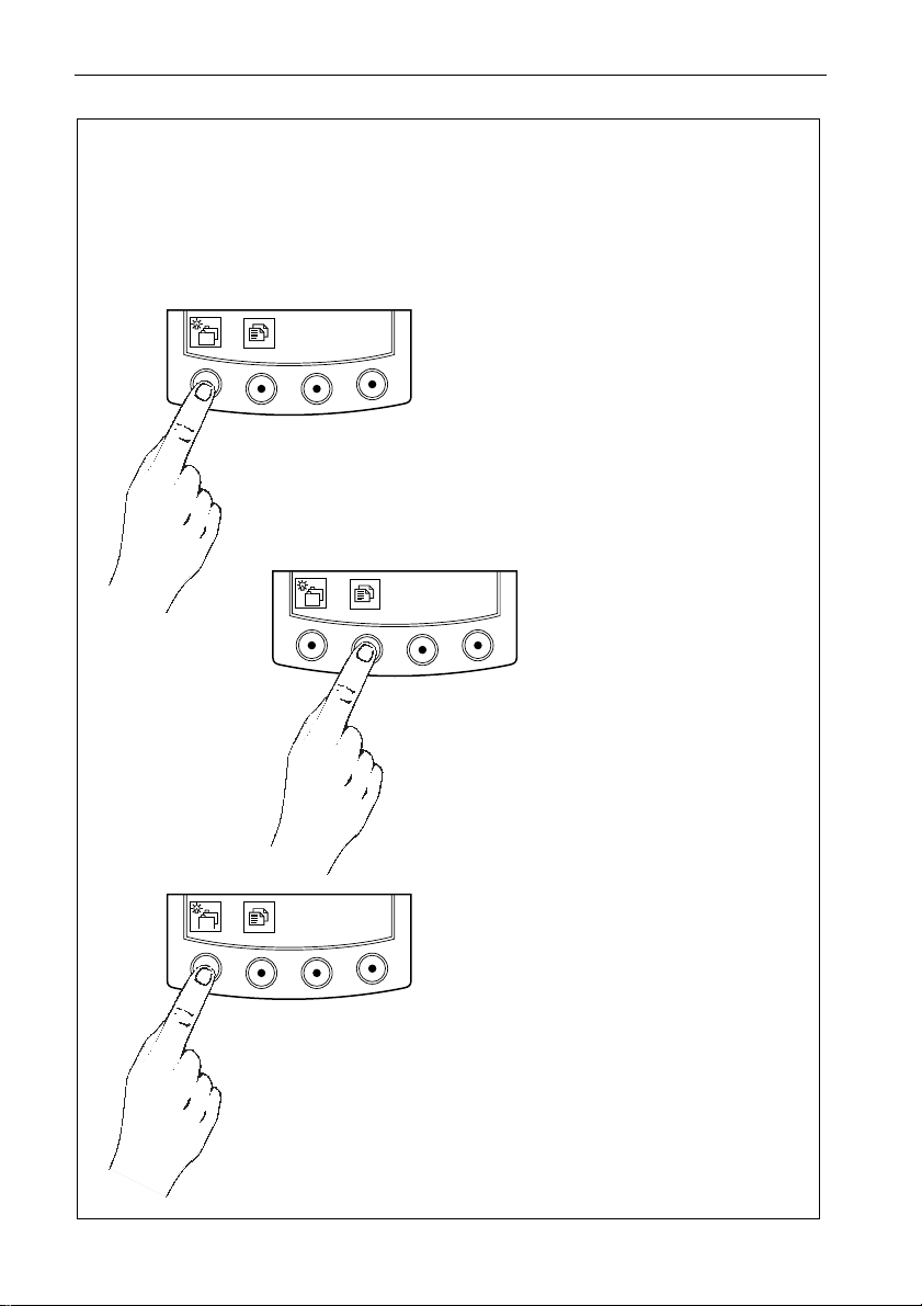
This chart shows the complete Masterview chapter and page configuration.
Chapters and pages can be switched off to reduce the total number of displays.
CHAPTERS
Use this key to cycle the available
chapters.
You can return to the previous
chapter pressing this key for 1
second - this action must be carried
within 2 seconds when entering a
new chapter.
PAGES
Use this key to cycle pages
within chapters.
Press this key for 1 second
to return to the previous
page.
ILLUMINATION
Press this key for 1 second to
switch the LCD illumination on.
Once the illumination is on, press
this key momentarily to change the
illumination settings.
D2759-1
Page 20
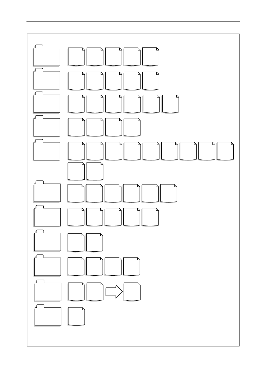
ST80 Masterview Operation and Setup 17
SPEED
CHAPTER
DEPTH
CHAPTER
WIND
CHAPTER
HEADING
CHAPTER
NAVIGATE
CHAPTER
PILOT
PILOT
CHAPTER
CHAPTER
TIMERS
CHAPTER
SPEED VMG SPEED
DEPTH
DEPTH
TRUE
WIND
HEADING
& COG
COURSE
ROUTE ROUTE
STATUS NAVI-
LOCAL
TIME
STATUS
STATUS NAVI-
STATUS NAVI-
UTC LOCAL
MIN
APP.
WIND
TACK
LIST
FIX
GATE
GATE
GATE
TIME
TRIP &
DEPTH
OFFSET
BEAU-
FORT
HDG &
STEER
WAYP'NT
STEER-
ALARM
TIMER
LOG
LIST
ING
AVG/MAX
SPEED
FISH
FINDER
WIND
HISTORY
HDG &
COG
HISTORY
LEG
INFO
GENERAL
STOP-
WATCH
SPEEDSPEED
SPEED
HISTORY
DEPTH
HISTORY
DOCK-
ING
SINGLE
WAY-
POINT
TIME
RACE
START
WIND
STEER
NAVIGATE
WIND
STEER-
ING
POSITION GENERAL
ENVIRONMENT
CHAPTER
NAV STATUS
CHAPTER
MULTILINE
CHAPTER
MAXIVIEW
REMOTE
VOLTAGE
HISTORY
DATA
SOURCE
2-LINE
PAGE
REMOTE
CONTROL
SEA
TEMP
HISTORY
FIX
STATUS
3-LINE
PAGE
GENERAL SATELL-
ITE PLOT
UP TO
8
PAGES
D2758-1
Page 21
18 ST80 Masterview Operation and Setup
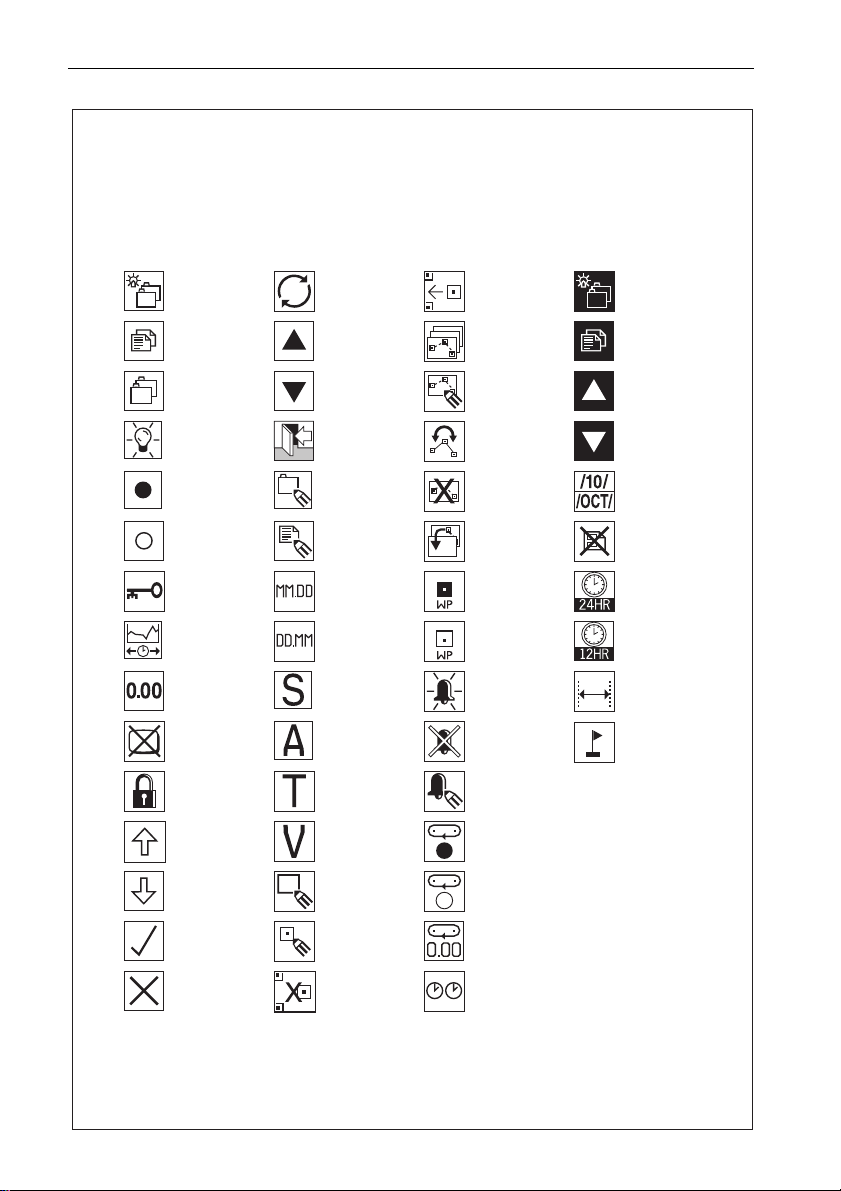
Icon Guide
The Masterview uses icons to identify specific keypad functions. The following
list shows the complete range of keypad icons togther with a brief description
of the icons primary function(s).
Cycle Chapters or
turn illumination
ON
Cycle Pages
Chapter
Illumination
Start
stop
Heading or wind
steer lock/unlock
Change history or
timebase
Reset
Remove display
pop-up
CodeLock
Scroll up
Cycle or change Insert WP or
Increase
Decrease
Exit
Edit Multiline
chapter
Edit
Change to US
date format
Change to EURO
date format
* Autopilot
STANDBY mode
* Autopilot AUTO
mode
* Autopilot
TRACK mode
* Autopilot VANE
mode
return to WP list
& save changes
Route select
Edit route
Reverse route
Delete route
Copy external
route
Track to waypoint
Stop tracking to
waypoint
Select alarm
adjustment page
Cancel alarms
Edit alarms
Lap start
Change Chapter
on selected
Maxiview
Change page on
selected
Maxiview
Select Maxiview
Select Maxiview
Change month
format
Delete multiline
page
Change to 24hr
clock
Change to 12hr
clock
Auto linearise for
log calibration
Drop event mark
Scroll down
Yes, enable or
turn ON
NO, disable or
turn OFF
New waypoint
Edit waypoint
Delete waypoint
Lap stop
Lap reset
Synchronise race
timer and guns
* Displayed only when this option has been selected in User Setup
D2757-2
Page 22
ST80 Masterview Operation and Setup 19
1.2 First-Time Power-Up
When the Masterview is powered up for the first time you are
presented with the “SELECT TYPE” page.
Use this page to select your vessel type (sail or power).
Press to advance to the next
masterview
SELECT TYPE
SAIL BOAT
POWER BOAT
✓
✕
Points to remember...
• The selected operating mode is identified by a ✔.
• Non-selected operating modes are identified by a ✖.
• If a permanent selection has not been made, the “SELECT TYPE”
display defaults to “SAIL”.
chapter. Press for 1 second
to select illumination
adjustment.
Highlight previous option.
Highlight next option.
Switch highlighted option
ON/OFF
or
D2227-1
Page 23
20 ST80 Masterview Operation and Setup
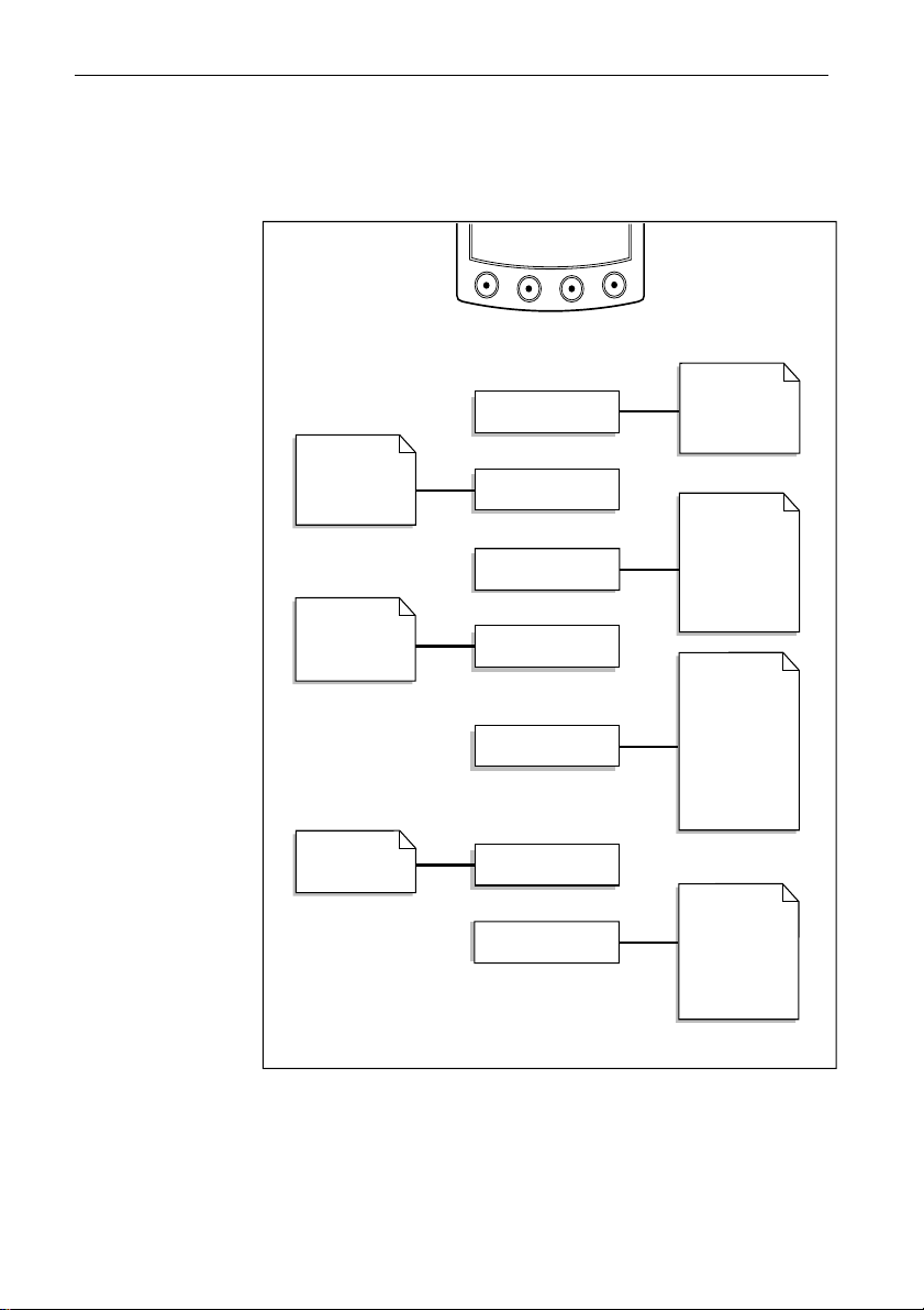
Sail Mode
The following flow chart shows the “SAIL” chapter and page
configuration.
Speed
VMG to Wind
Trip/Log
Average/maximum
True wind
speed & direction
App wind speed &
direction
Beaufort &
magnetic wind
direction
Route track
Route List*
Waypoint List*
Current Leg
Navigate
Steering (XTE)
Position & log
Local Time
Fix
Depth
Minimum depth
Depth offset
Histogram
Heading/COG
Tack course
Heading steer
SPEED CHAPTER
DEPTH CHAPTER
WIND CHAPTER
HEADING CHAPTER
NAVIGATE CHAPTER
Status
Wind
PILOT CHAPTER
MULTILINE CHAPTER
SOG & COG
Depth & Speed
Speed & Heading
BTW & COG
VMG & Tack angle
DTW & ETA WPT
D2042-1
Chapters only appear if the associated transducer is transmitting
information onto the SeaTalk bus.
Note: Chapters are turned off (and replaced with a warning page) if related
SeaTalk data is lost for more than 2 seconds.
Pages identified by an asterisk (*) are only available if the
Masterview has been linked to a Navigator keypad.
Page 24
ST80 Masterview Operation and Setup 21
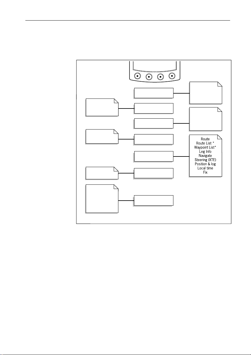
Power Mode
If “POWER” is selected, the following chapters and pages are
available during normal operation.
Speed
Trip/Log
Average/maximum
Sea Temperature
True wind
speed & direction
Beaufort
Cardinal point
Mag wind direction
Depth
Depth Offset
Histogram
Heading/COG
Heading steer
SPEED CHAPTER
DEPTH CHAPTER
WIND CHAPTER
HEADING CHAPTER
NAVIGATE CHAPTER
Status
SOG & COG
Depth & speed
Speed & heading
BTW & COG
DTW & ETA to wpt
Depth & sea temp
AUTOPILOT
MULTILINE CHAPTER
D2043-1
Chapters only appear if the associated transducer is transmitting
information onto the SeaTalk bus.
Note: Chapters are turned off (and replaced with a warning page) if related
SeaTalk data is lost for more than 2 seconds.
Pages identified by an asterisk (*) are only available if the
Masterview has been linked to a Navigator keypad.
Page 25
22 ST80 Masterview Operation and Setup
1.3 Operation
The chapter and page concept allows you to configure multiple
display heads for different functions (for example, speed, depth,
wind, position, heading) or, alternatively, a single head to display as
much or as little data as you require.
About this Chapter
This chapter describes how to operate the Masterview using a
combination of text, diagrams and flow charts.
The flow charts show the display roll-over for a particular key or key
sequence. If a display is adjustable, related information follows the
flow chart in display roll-over order.
Points to remember...
• All key presses in the flow charts are momentary (unless stated
otherwise).
• You can return to the previous chapter by pressing the chapter key
for 1 second, providing the chapter key is pressed within 2 seconds
otherwise illumination adjustment will be turned on.
Speed Chapter
SPEED
CHAPTER
PAGES
Boat
Speed
Sea
Temp
VMG to
Wind
Trip or
Log
Avg/Max
Speed
Speed
histogram
D2050-1
Page 26
ST80 Masterview Operation and Setup 23
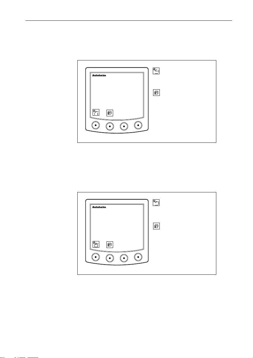
Boat Speed Page
The boat speed units can be displayed in KNOTS, MPH or KM/H.
Units are selected in “User Setup”.
Press this key to advance to
masterview
SPEED
8.35
KTS
the next chapter. Press for 1
second to select illumination
adjustment.
Press this key to cycle the
pages within this chapter.
Press for 1 second to return
to the previous page.
D2230-1
If the rate at which the boat speed changes is greater than the value
assigned in User Setup, trend indicators ▲ (faster) ▼ (slower) are
displayed alongside the units.
VMG to Wind Page
This page is not available in “Power” mode.
Press this key to advance to
masterview
VMG TO WIND
8.35
KTS
the next chapter. Press for 1
second to enter illumination
adjustment.
Press this key to cycle the
pages within this chapter.
Press for 1 second to return
to the previous page.
D2238-1
• The displayed units, Statute Miles, Nautical Miles or Kilometres,
are dependent on the units selected in User Setup.
• If the rate at which VMG to Wind data changes is greater than the
User Setup value, trend indicators ▲ (faster) ▼ (slower) are
displayed.
Page 27
24 ST80 Masterview Operation and Setup
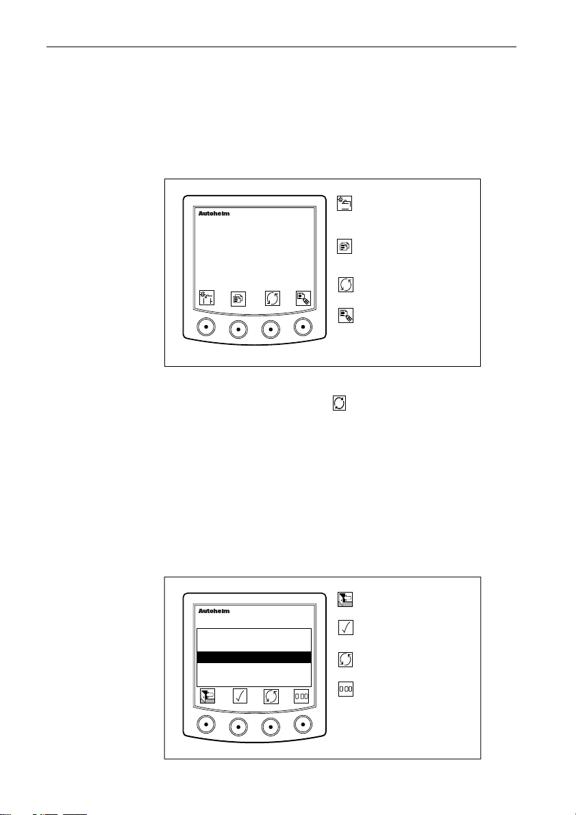
Trip/Log Page
The Trip/Log page displays the current boat speed, the accumulated
distance (log), and one of the five trip counters.
• The maximum recordable trip distance is 9999.9 nautical miles.
• The log records the total distance up to 99999.9 nautical miles.
Next chapter. Press for 1
masterview
SPEED KTS
8.35
TRIP 2 1102.4NM
• Up to 5 trip distances can run at the same time.
• “TRIPS OFF” is displayed if the key is pressed when there are no
currently active trips.
• The “TRIPS OFF” message is cleared by pressing any key.
• Log data is recorded every 30 minutes (this is a fixed period and
cannot be adjusted.
second to enter illumination
adjustment.
Next page or press for 1
second to return to the
previous page.
Show next active trip or the
LOG display.
Display trip list and control
icons.
D2233-1
Trip Control Page
This page displays up to 5 trips which can be scrolled, reset and
switched ON/OFF as required. Operation of the trip functions is
described and illustrated below.
Return to Trip/Log display.
Turn highlighted trip
ON/OFF.
Highlight next trip.
Press for 4 seconds to reset
.
the currently selected trip to
zero.
D2236-1
TRIP
1
OFF
2
ON
3
OFF
4
OFF
OFF
5
masterview
NM
0.00
1102.4
20.19
0.00
50.84
.
Page 28
ST80 Masterview Operation and Setup 25
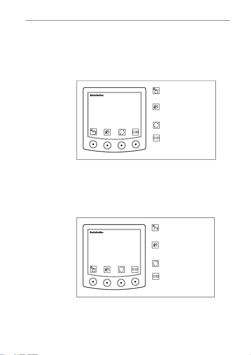
Average/Maximum Speed
This page displays the average or maximum boat speed for the
current journey.
Average Speed
Average boat speed is displayed in the units selected in User Setup.
Go to the next chapter or
masterview
SPEED AVG
8.35
KTS
.
• If the average speed calculation stops for any reason, the display
reads “STOPPED”.
• The display flashes for 4 seconds when the average speed is reset.
press for 1 second to enter
illumination adjustment.
Go to the next page. Press
for 1 second to return to the
previous page.
Toggle maximum & average
speed.
Press for 4 seconds to reset
.
the average speed to boat
speed.
D2226-1
Maximum Speed
This page displays the maximum speed achieved during the current
journey.
Go to the next chapter or
masterview
SPEED MAX
7.25
KTS
.
press for 1 second to enter
illumination adjustment.
Press to go to the next
page. Press for 1 second to
go to the previous page.
Toggle maximum & average
speed.
Press for 4 seconds to reset
.
the maximum speed to zero.
D2781-1
• The display flashes for 4 seconds when the maximum speed is reset.
Page 29
26 ST80 Masterview Operation and Setup
Speed Histogram
The histogram displays a graph of your boat speed for a selected
period of time. The following illustration shows a typical example
of a speed histogram.
masterview
SPEED
8.73 KTS
1HR
Go to the next chapter.
Press for 1 second to enter
illumination adjustment.
Go to next page. Press for 1
second for previous page.
Select time scale for
histogram 1 and 10min, 1hr,
6hr, 24hr.
D2234-1
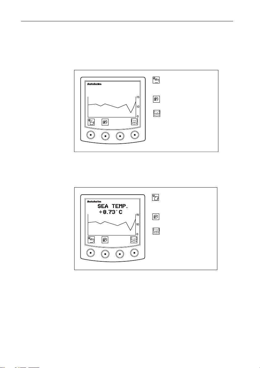
Sea Temperature
This page displays the current sea temperature as well as a graph
depicting the sea temperature for a selected period of time.
masterview
1HR
Go to the next chapter.
Press for 1 second to enter
illumination adjustment.
Go to next page. Press for 1
second for previous page.
Select time scale for
histogram 1 and 10min, 1hr,
6hr, 24hr.
D4137-1
Page 30
ST80 Masterview Operation and Setup 27
Depth Chapter
DEPTH
CHAPTER
PAGES
Water
Depth
Minimum
Depth
Depth
Offset
Fish
Finder
Depth
Histogram
Water Depth
The depth can be displayed in feet, fathoms or metres. However, the
currently displayed units are those selected in User Setup.
Go to the next chapter.
masterview
DEPTH
5.35
FT
If the rate at which the water depth changes is greater than the value
in User Setup, trend indicators ▲ (decreasing) or ▼ (increasing) are
displayed alongside the units.
What if the depth echo is lost?
• The last valid echo remains on screen until a new valid echo is
received.
• The words “LAST ECHO” are displayed.
Press for 1 second to enter
illumination adjustment.
Go to next page or press for
1 second to return to the
previous page.
Display shallow, deep and
anchor alarms.
D2239-1
D2057-1
Page 31

28 ST80 Masterview Operation and Setup
Depth Alarm Control
The alarm control page displays the current settings for the shallow,
deep and anchor alarms.
Return to the main depth
masterview
DEPTH ALARMS
SHALLOW 10FT
DEEP 200 FT
SHAL 50 FT
DEEP 70 FT
✕
✓
✓
✓
• Anchor alarms cannot be turned off individually.
• Anchor alarms are both on or both off.
Editing the Depth Alarms
Set the depth alarms using the keys as shown.
The depth alarms can be set and turned ON/OFF as follows:
page.
Highlight previous alarm.
Highlight next alarm.
Display alarm edit icons.
D2240-1
Press to return to the depth
masterview
DEPTH ALARMS
SHALLOW 10FT
DEEP 200 FT
SHAL 50 FT
DEEP 70 FT
▼
▼
✕
✓
✓
✓
alarm control page.
▼
Decrease alarm.
Increase alarm.
▼
Switch highlighted alarm
ON/OFF.
or
D2241-1
• The maximum depth is 122m (400ft) with a standard active depth
transducer and 244m (800ft) with the “deep depth” transducer.
• The shallow alarm range is from 3 to 30ft (0.8 to 9m).
• The shallow alarm cannot be set above the deep alarm and the deep
below the shallow.
• Conversions from feet to fathoms/metres are rounded up/down, for
example, 4.2 feet = 1.3 metres or 0.7 fathoms.
Page 32

ST80 Masterview Operation and Setup 29
Minimum Depth
This page displays the minimum depth recorded during the current
journey.
Go to the next chapter.
DEPTH MIN
masterview
20.5
.
Press for 1 second to enter
illumination adjustment.
Press to go to the next page
or press for 1 second to
return to the previous page.
Press for 4 seconds to reset
.
minimum depth to the
current depth.
D2242-1
• This page also displays the time when the minimum depth was
recorded, providing the required information is available.
• The display flashes for 4 seconds when the minimum depth is reset.
Depth Offset
Depth offset displays the amount and type of depth transducer
offset: waterline (positive), keel (negative) or transducer (zero).
DEPTH OFFSET
masterview
-4.OFT
KEEL
Go to the next chapter.
Press for 1 second to enter
illumination adjustment.
Go to the next page.
Press for 1 second to return
to the previous page.
D2621-1
Page 33

30 ST80 Masterview Operation and Setup
Fish Finder
The fishfinder page displays a graphic representation of the sea-bed
and the size of fish in the area of detection.
The default fish finder display shows:
• The current depth.
• A boat symbol to indicate the most recent data.
masterview
38.4
Go to next chapter.
Press 1 second to enter
illumination adjustment.
Press to go to next page.
Press for 1 second to return
to previous.
Display split screen and
show sensitivity and gain
editing icons.
Display split screen only.
D2243-1
When the split screen is selected, the rate, sensitivity and gain
settings are displayed on the left.
masterview
RATE
8
SENS
50
GAIN
20
38.4
Note: The split-screen times-out to the full screen display after 8 seconds of
keypad inactivity.
Go to the next chapter.
Press for 1 second to enter
illumination adjustment.
Go to the next page.
Press for 1 second to return
to the previous page.
Show sensitivity and gain
adjustment icons.
Adjust rate (range 1 to 8
plus OFF).
D2244-1
Page 34

ST80 Masterview Operation and Setup 31
Rate
• Controls the speed at which the fish finder information is updated.
• The range is from 1 to 8 plus OFF (the fastest setting is 1).
Sensitivity (SENS) and Gain
To adjust sensitivity and gain, you must press to change the
current icons to the adjustment icons.
The key is used to highlight sensitivity or gain as required.
Sensitivity
You can control the size of the fish that will be detected by adjusting
the sensitivity.
• A high setting (the range is from 0 to 100) detects smaller fish.
• A lower setting detects larger fish.
Gain
The amount of data displayed at any one time is governed by the
gain setting — the higher the setting (the range is from 0 to 100) the
more data is displayed.
masterview
38.4
Restore previous keypad icons.
▼
Increase value of highlighted field.
Decrease value of highlighted field.
▼
Highlight next field.
D2064-1
Page 35

32 ST80 Masterview Operation and Setup
Depth Histogram
The depth histogram displays the current depth and a graph of the
depth soundings for a selected period of time.
masterview
DEPTH
45.0 FT
Go to the next chapter.
Press 1 second to enter
illumination adjustment.
Press to go to next page.
Press for 1 second to return
to the previous page.
1HR
Select time scale for
histogram: 1min, 10min,
1hr, 6hr, 24hr.
Wind Chapter
The complete wind chapter consists of the following pages.
WIND
CHAPTER
PAGES
True
wind
Docking
Apparent
wind
Wind
Steer
Beaufort
scale
True wind
speed or
angle
histogram
D2066-1
D2245-1
Page 36

ST80 Masterview Operation and Setup 33
True Wind
This page displays the true wind speed and true wind angle relative
to the ships head. The wind direction is identified by a P (port) or S
(starboard) indicator.
Go to the next chapter.
masterview
WIND TRUE
4.5
KTS
120o
P
• Wind speed is “sailing wind speed”
• Wind angle is “relative sailing wind angle”.
• Alarms can be set for true wind to warn you of increasing or
decreasing wind speeds and changes to the wind angle.
Press for 1 second to enter
illumination adjustment.
Go to the next page or press
for 1 second to return to the
previous page.
Display true wind alarms.
D2246-1
Alarm Control
Alarm control displays the current high and low speed, and high and
low wind angle alarms.
Press to return to the main
wind page.
Highlight next alarm.
Highlight previous alarm.
Display alarm adjustment
icons.
D2247-1
10 KTS
2 KTS
10
masterview
✓
✓
✕
✕
WND TRU ALRM
HIGH
LOW
HIGH 25
LOW
Alarm Adjustment
• The wind alarms can be turned ON and OFF as and when required.
• A highlighted alarm that is ON has a displayed above the righthand key, and a when it is OFF. Press to turn an alarm “OFF”
and to turn an alarm “ON”.
Page 37

34 ST80 Masterview Operation and Setup
• Set the alarms using the or keys. The maximum wind speed
is 60 knots.
• The maximum wind angle is 180°.
• Once you have adjusted an alarm, press to return to the wind
alarm display.
Apparent Wind
Apparent wind displays the apparent wind speed and wind angle.
The wind direction is identified by a P for port or an S for starboard.
Alarms can be set for apparent wind to warn you when:
• the wind speed increases or decreases.
• the wind angle changes.
Go to the next chapter.
WIND APP
4.5
masterview
KTS
100
P
Press for 1 second to enter
illumination adjustment.
Go to the next page or press
for 1 second to return to the
previous page.
Display settings for apparent
wind alarms.
D2326-1
Alarm Control
This page displays the current settings the high and low speed and
high and low wind angle alarms.
Alarm Adjustment
Adjustment is identical to true wind.
Page 38

ST80 Masterview Operation and Setup 35
Beaufort Scale
This page displays true wind as a Beaufort scale. The wind angle
(true or magnetic) and wind direction is also displayed.
Go to the next chapter.
masterview
6
• If SOG is available, the Beaufort reading is taken from the ground
wind speed and the wind angle from the true ground wind angle.
• If SOG is not available, the Beaufort reading is taken from the
sailing wind speed and the wind angle from the true sailing wind
angle.
Press for 1 second to enter
illumination adjustment.
Press to go to the next page
or press for 1 second to
return to the previous page.
D2248-1
True Wind Histogram (Speed and Angle)
The histogram displays a graph of the true wind speed and angle for
a given period of time.
Go to the next chapter.
Press for 1 second to enter
illumination adjustment.
Go to the next page.
Press for 1 second to return
to the previous page.
Display true wind angle
histogram or return to true
wind angle from true wind
speed.
Select time scale: 1min,
10min, 1hr, 6hr or 24hr.
• Ground wind speed is recorded if SOG is available.
• Sailing wind speed is recorded if SOG is not available.
• Wind speed is shown in the currently selected units.
Note: This display is not active if you have selected “power” mode.
D2249-1
Page 39

36 ST80 Masterview Operation and Setup
Docking (Power and Custom Modes only)
The docking page displays a graphic representation of the effect the
wind is having on your vessel. The screen shows the wind speed and
the wind direction.
Advance to next chapter or
press for 1 second to adjust
illumination.
Next page or
press for 1 second to return
40 30 20 10 0 10 20 30 40
to the previous page.
D4051-1
Apparent Wind Steer
The apparent wind steer pages operate in an almost identical manner
to the heading steer pages.
Go to the next chapter.
masterview
WIND p PORT
- - -
UNLOCKED120
Press for 1 second to enter
illumination adjustment.
Press this key to advance to
the next page or press for 1
second to return to the
previous
Press to store the current
wind angle as the locked
value.
Enter locked mode.
D2255-1
• Apparent wind steer is not available if you have selected
“power” mode.
• The current apparent wind angle is identified by ~ symbol.
Locked Mode
When lock mode is engaged, the apparent wind angle is stored as a
datum. Any deviation from this datum is displayed together with a
direction-to-steer indicator.
Page 40

ST80 Masterview Operation and Setup 37
Go to the next chapter or
masterview
WIND p PORT
HEAD
+012
132
LOCK
press for 1 second to enter
illumination adjustment.
Press to advance to the next
page or press for 1 second to
return to the previous page.
Display locked apparent wind
angle adjustment icons.
Return to the unlocked mode.
D2256-1
There are two operating modes: locked and fixed. These modes are
similar to those described in Heading to Steer.
• A head/lift (freeing) indicator is displayed when applicable.
Adjusting a Locked Apparent Wind Steer
A “locked apparent wind steer” can be adjusted in 1° increments by
entering “locked apparent wind control”.
Autopilot Locked
This page displays the difference between the autopilot “locked
apparent” and “current apparent” wind angles. A steering indicator
shows the direction to steer to correct any error.
Go to the next chapter.
masterview
WIND PORT
LIFT
118
001
AUTO
Press for 1 second to enter
illumination adjustment.
Press to go to the next
page.
Press for 1 second to return
to the previous page.
D2625-1
There are two operating modes: current and fixed.
• Current: the current “live” apparent wind angle (identified by a ~)
is displayed at the bottom left of the display and the locked value as
a positive (starboard) and a negative (port) reading up to 30°. The
arrows indicate the direction to steer to correct any error.
Page 41

38 ST80 Masterview Operation and Setup
• Fixed: the locked apparent wind angle is displayed at the bottom left
of the display and the locked value as a positive (starboard) and a
negative (port) reading up to 30°. The arrows indicate the direction
to steer to correct any error.
• A head head/lift (freeing) indicator is displayed when applicable.
Heading Chapter
The heading chapter contains the following pages.
HEADING
CHAPTER
PAGES
Heading
& course
over
ground
Tack
course
Heading
steer
HDG/COG
Histogram
D2071-1
Heading and Course Over Ground
These pages display the heading and course over ground in degrees
true or magnetic (depending on your selection in User Setup).
Go to the next chapter.
masterview
HEADING
120
TRUE
Press for 1 second to enter
illumination adjustment.
Go to the next page.
Press for 1 second to return
the previous page.
Switch between heading and
COG displays.
D2250-1
Page 42

ST80 Masterview Operation and Setup 39
Go to the next chapter or
press for 1 second to enter
illumination adjustment.
Press this key to go to the
next page.
Press for 1 second to return
to the previous page.
Switch between heading and
COG displays.
D2251-1
Tack Course
This page displays your tack course in degrees true or magnetic
(depending on your selection in User Setup).
Go to the next chapter.
masterview
TACK COURSE
120
TRUE
Press for 1 second to enter
illumination adjustment.
Go to the next page.
Press for 1 second to return
to the previous page.
D2252-1
• This page is not available if you have selected “power” mode.
Page 43

40 ST80 Masterview Operation and Setup
Heading Steer
Heading steer allows you to lock onto a heading and view any
subsequent changes between the locked and current headings.
Unlocked Mode
This mode displays your current heading (identified by a ~) only.
Go to the next chapter or
masterview
HEADING TRUE
120
UNLOCKED
Off Course Alarm
An off-course alarm can also be set from the “heading steer” page.
You can also turn an existing alarm off.
press for 1 second to enter
illumination adjustment.
Press to advance to the next
page. Press for 1 second to
return to the previous page.
Press to turn to the Off
Course Alarm page.
Enter locked compass
heading mode.
D2253-1
masterview
OFF COURSE
ALARM
RANGE 010
✓
or
• The maximum off-course alarm is 180°.
Press to return to the
unlocked page and transmit
alarm status.
Increases alarm in 1 degree
increments.
Decrease alarm in 1 degree
increments.
Turn the off-course alarm
on/off.
D2622-1
Page 44

ST80 Masterview Operation and Setup 41
Locked Mode
In locked mode, this page displays the difference between a locked
and current heading.
Go to the next chapter or
masterview
HEADING TRUE
120
LOCK
press for 1 second to enter
illumination adjustment.
Press to advance to the next
page. Press for 1 second to
return to the previous page.
Display locked heading
control icons.
Select unlocked mode.
D2760-1
Locked mode can be configured in User Setup to show either the
current or locked (fixed) heading.
• Current: the current “live” heading (identified by a ~) is displayed
at the bottom left of the LCD and the difference between the locked
and current as a positive (starboard) or a negative (port) value up to
30°. Arrows indicate the direction to steer to correct the error.
• Fixed: the locked heading is displayed at the bottom left of the LCD
and the difference between the locked and current as a positive
(starboard) or a negative (port) value up to 30°. Once again, arrows
indicate the direction to steer to correct the error.
Page 45

42 ST80 Masterview Operation and Setup
Adjusting a Locked Heading
A locked heading may be adjusted in 1° increments by entering
“locked heading control” mode (below).
Press to return to the
masterview
HEADING TRUE
previous display -- the new
locked heading is now
active.
Decrease locked heading.
LOCK
Increase locked heading.
Select unlocked mode.
D2623-1
• If a SeaTalk autopilot is connected to the system, the “heading steer”
page automatically switches from unlocked to locked mode when
AUTO is engaged.
• The display identifies this change by displaying AUTO in the right
hand corner of the screen.
Heading Histogram (True and Course Over
ground)
The histogram displays a graph of the true heading and course over
ground for a selected period of time.
HEADING
masterview
120 TRUE
1HR
Go to the next chapter.
Press for 1 second to enter
illumination adjustment.
Go to next page. Press for 1
second to return to the
previous.
Switch between true heading
and course over ground
histograms.
Select histogram time scale:
1min, 10min, 1hr, 6hr or
24hr.
D2257-1
Page 46

ST80 Masterview Operation and Setup 43
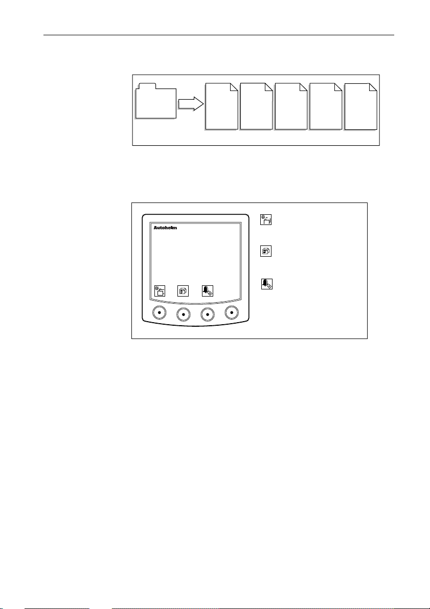
Navigate Chapter
Chapter Structure
The Navigate chapter contains the following ‘pages’.
This chapter is handled in a different manner to the previous and
subsequent chapters in this handbook. The reason for changing the
approach is due to the way in which you have assemble route and
waypoint data.
Before a route can be created, waypoints must be entered into the
waypoint list. Once you have entered your chosen waypoints, a
route can then be constructed.
General Route and Waypoint Information
The Navigate chapter allows you to:
• create up to 800 waypoints
• create and name up to 20 routes
• create up to 50 waypoints per route using Lat/Lon
• import a route from an external ‘navigator’
• create and track to a single destination waypoint
Note: The Masterview displays illustrated in this section are
representations only.
Entering Information
Waypoint and route information is entered using the Autohelm
Navigator keypad only.
If ST80 Masterview instruments have been linked to specific
Navigator keypads, information can only be entered or modified
using the linked units.
Page 47

44 ST80 Masterview Operation and Setup
If linking has not taken place, information can be entered or
modified from any Navigator keypad.
Waypoints
Before you begin to generate a route, you must create and store
waypoints in the waypoint list.
Entering New Waypoints
Cycle the Navigate Chapter until you come to ‘Waypoint List’ and
then follow the instructions below:
Entering New Waypoints
WAYPOINT LIST
BELL POINT
COWES
2
1
def3ghi
abc
5mn6
4
jkl
8
7
uvw9xyz
rst
0
opq
delins
NEW WAYPOINT
NAME --------------------LAT ---:--.-- LON ---:--.-- -
Use these keys to enter the name and
co-ordinates for the new waypoint.
Each key cycles the number and the
letters printed on that key (e.g. cycle of
key 1 is 1, a, b, c, 1 etc.)
Use these keys to insert or delete data
at the cursor position.
Use the multi-directional trackpad keys
to move the cursor.
NEW WAYPOINT
WAYPOINT LIST
BELL POINT
COWES
NAB TOWER
• If the waypoint catalogue is full, the new waypoint icon is
disabled until a waypoint has been deleted from the catalogue.
• If you want to return to the waypoint list without adding the
waypoint, simply press the exit ( ) key.
NEW_WPT
• To return to the edit display and display dashes, press delete .
Page 48

ST80 Masterview Operation and Setup 45
Editing a Waypoint
Cycle the display until you come to ‘Waypoint List’ and then follow
the instructions illustrated below:
Editing a Waypoint
Scroll - Use the Navigator up
2
1
def3ghi
abc
5mn6
4
jkl
8
7
uvw9xyz
rst
0
or down key to highlight the
waypoint, or press any
alphanumeric key to open the
opq
'Waypoint Search' feature.
Search - Use the Navigator
keypad to enter the first
delins
character of the waypoint
name. If there are multiple
waypoints beginning with that
letter, type in additional
characters until the required
waypoint is highlighted.
2
1
def3ghi
abc
5mn6
4
jkl
7
rst
8
uvw9xyz
0
opq
delins
WAYPOINT LIST
BELL POINT
COWES
NAB TOWER
EDIT WAYPOINT
Move the cursor to
highlight the data to
edit using the Navigator
Keypad cursor keys.
2
1
def3ghi
abc
5mn6
4
jkl
7
rst
8
uvw9xyz
0
opq
delins
Use these keys to enter new waypoint data.
Each key cycles the number and the letters
printed on that key (e.g. cycle of key 1 is 1,
a, b, c, 1 etc.)
Use these keys to insert or delete data at
the cursor position.
Use the multi-directional trackpad keys to
move the cursor.
EDIT WAYPOINT
Press to return to the
Waypoint List without
making changes or...
WAYPOINT LIST
BELL POINT
COWES
TAB TOWER
Press to return to the
Waypoint List and save
changes.
• If a target waypoint (identified in the waypoint list by the letter
‘T’) is being tracked, then the edit key is disabled and that
particular waypoint cannot be edited.
• If the waypoint is used in a route, a message similar to “WP
USED IN 4 ROUTES CHANGE ALL?” will be displayed before
the changes are saved.
EDITWPT
Page 49

46 ST80 Masterview Operation and Setup
Deleting a Waypoint
Cycle the display until you come to ‘Waypoint List’ and then follow
the instructions illustrated below:
Deleting a Waypoint
WAYPOINT LIST
BEMBRIDGE
BOURNMOUTH
BOWRING
BRACKLESHAM BAY
CHERBOURG
CHICHESTER
2
1
def3ghi
abc
5mn6
4
jkl
8
7
uvw9xyz
rst
0
Scroll - Use the Navigator up
or down key to highlight the
waypoint to be deleted or
press any alphanumeric key
opq
to open the 'Waypoint
Search' feature...
Waypoint Search - Use the
delins
Navigator keypad to type in
the first character of the
waypoint to be deleted.If
there are multiple waypoints
beginning with that letter,
type in additional characters
until the required waypoint
2
1
def3ghi
abc
5mn6
4
jkl
7
rst
8
uvw9xyz
0
opq
delins
name is highlighted.
WAYPOINT LIST
N------------------------------
CHERBOURG
CHICHCHESTER
CHRISTCHURCH
LYMINGTON
NAB TOWER
EDIT WAYPOINT
4
EDIT WAYPOINT
YES or
NO
5
What if the Waypoint is Used in Routes?
If the waypoint you want to delete is used in one or more routes, the
message ‘USED IN ROUTE’ will be displayed and you will not be
allowed to delete it.
To delete the waypoint it must first be removed from all routes.
DELWPCAT
Page 50

ST80 Masterview Operation and Setup 47
Adding Event Marks
Event marks can also be added to the waypoint list. An event name
is automatically created using the current date, and time, and is
preceded with the letters EV.
To create an event mark, proceed as follows:
Adding an Event Mark
WAYPOINT LIST NEW WAYPOINT
NAME ..........................................
LAT ..... ...... ........ ......
LON ..... ...... ........ ......
NEW WAYPOINT
NEW WAYPOINT
4
WAYPOINT LIST
5
Route Page
The Route feature allows you to create, name and store up to 20
routes comprising of up to 50 waypoints from the waypoint list.
INS_MARK
Page 51

48 ST80 Masterview Operation and Setup
Creating a Route
Cycle the pages in the Navigate Chapter until ‘ROUTE LIST’ is
displayed. To create a new route, follow the instructions below.
Creating a New Route
ROUTE LIST
02 COWES
03 CHERBOURG
04 DOVER
05 ------------------- E
06 ------------------- E
Press the up or
down Navigator
key to highlight
any empty route.
ROUTE 05
----------------------------
START
01 END
Enter a route
name using
the Navigator
Keypad.
2
1
def3ghi
abc
5mn6
4
jkl
8
7
uvw9xyz
rst
0
Use these keys to enter
data at the current cursor
position (e.g. cycle of key 1
is 1, a, b, c, 1 etc.)
opq
Use these keys to insert a
delins
space or delete data at the
cursor position.
Use the multi-directional
trackpad keys to move
the cursor.
ROUTE 05
LYMINGTON
START
01 END
Press the up or down
Navigator key to
highlight the first
waypoint entry (-01).
Now turn the page and add waypoints as shown
ROUTE 05
LYMINGTON
START
01 -
END
6
NEWROUT2
Page 52

ST80 Masterview Operation and Setup 49
Adding Waypoints
Press the first character of
2
1
def3ghi
ROUTE 05
LYMINGTON
START
01 -
END
abc
4
jkl
7
uvw9xyz
rst
the required waypoint name.
5mn6
The display will jump to the
opq
waypoint list which can be
8
scrolled using the Navigator
Keypad cursor keys (see
0
below).
SELECT WP
----------------------------
BROWNDOWN
BEMBRIDGE LED
CULVER SPIT
DEAN ELBOW
SELECT WP
SH----------------------SANDOWN BAY
SHANKLIN
THE NEEDLES
YARMOUTH
ROUTE 05
LYMINGTON
START
01 SHANKLIN
02
END
ROUTE 05
LYMINGTON
START
01 SHANKLIN
02 VENTNOR
END
ROUTE LIST
00 ROUND ISLAND
02 COWES
03 CHERBOURG
04 DOVER
O5 LYMINGTON
Waypoint Scroll
Press and hold the up or down
Navigator key to scroll the list of
waypoints.
OR
2
1
def3ghi
abc
5mn6
4
jkl
8
7
uvw9xyz
rst
0
Waypoint Search
Use the Navigator keypad to
type in the next character of the
opq
required waypoint. If there
are multiple waypoints beginning
with that letter, type in additional
characters until the required
waypoint name is highlighted.
Press this key to insert the highlighted
waypoint to the route and return to the
route contents display.
Repeat the above actions from stage 2
above to add further waypoints to the
route.
Once all the waypoints have been
inserted, press the exit key to return to the
route list display.
FINDWPT
Page 53

50 ST80 Masterview Operation and Setup
Deleting Waypoints from a Route
Cycle the Navigate Chapter until the ‘Route List’ is displayed.
Deleting a Waypoint from a Route
ROUTE LIST
02 COWES
03 CHERBOURG
04 DOVER
05 LYMINGTON
06 ------------------- E
ROUTE 05
LYMINGTON
START
01 SHANKLIN
02 VENTNOR
END
Highlight the
required route
using the
Navigator
Keypad
Highlight the
waypoint to be
deleted using
the Navigator
up or down key.
ROUTE LIST
02 COWES
03 CHERBOURG
04 DOVER
05 LYMINGTON
06 ------------------- E
ROUTE 05
LYMINGTON
START
01 SHANKLIN
02 VENTNOR
END
ROUTE 05
LYMINGTON
START
01 SHANKLIN
02 VENTNOR
END
Press the delete
key to display
the 'Delete
Waypoint?'
pop-up.
Press to remove
the selected
waypoint from
the route.
ROUTE 05
LYMINGTON
START
01 SHANKLIN
02 VENTNOR
END
ROUTE 05
LYMINGTON
START
01 SHANKLIN
02 -
END
What if I Decide that I Don’t Want to Delete the Waypoint?
Providing you have not already deleted the waypoint, simply press
the NO key instead.
Press the exit key to return to the ‘Route List’ page.
REMWPT
Page 54

ST80 Masterview Operation and Setup 51
Inserting a Waypoint in a Route
Cycle the Navigate chapter until ‘Route List’ is displayed.
Inserting a Waypoint in a Route
ROUTE LIST
02 COWES
03 CHERBOURG
04 DOVER
05 LYMINGTON
06 ------------------- E
Highlight the
required route
using the
Navigator up
or down key.
ROUTE LIST
02 COWES
03 CHERBOURG
04 DOVER
05 LYMINGTON
06 ------------------- E
Press the
'Edit Route'
key
ROUTE 05
LYMINGTON
Highlight the point at which
you want to insert a
waypoint using the
Navigator Keypad up or
down key.
ROUTE 05
LYMINGTON
START
01
02 SHANKLIN
03 VENTNOR
Press the insert key
to insert a new
waypoint. A space
for the waypoint will
be created before
the highlighted
point.
Insert a waypoint from
the Waypoint List as
described in section 5.2
'Adding Waypoints'.
5
Tracking to a Route Selected from the Route List
Cycle the navigate Chapter until the ‘Route’ page is displayed.
Selecting a Route
ROUTE
NO ROUTE
SELECTED
ROUTE SELECT
03 CHERBOURG
04 DOVER
05 NAB TOWER
06 CALAIS
07 YARMOUTH
08 LYMINGTON
ROUTE SELECT
0I ROUND ISLAND A
02 --------------------------E
03 CHERBOURG
04 DOVER
05 NAB TOWER
06 CALAIS
ROUTE 05
NAB TOWER
01 SAND FORT
BEARING 120
RNG 0.5NM
Use the up
or down key
to highlight
the route
you require.
INSERTWP
ROUTE 05
NAB TOWER
01 SAND FORT
BEARING 120
RNG 0.5NM
5
Press the
'Track' key to
begin tracking
the selected
route.
ROUTE 05
NAB TOWER
TRACKING
01 SAND FORT
BEARING 120
RNG 0.5NM
6
SELROUTE
Page 55

52 ST80 Masterview Operation and Setup
Waypoint Advance
When a route is being tracked, you can advance to the next waypoint
by selecting the ‘Route’ page and pressing for 1 second.
Deselecting a Route
A route can be deselected by highlighting route ‘00’ or an empty
route (identified by the letter ‘E’).
Deselecting a Route
ROUTE SELECTROUTE SELECT
ROUTE SELECT
DESELECT
Reversing the Direction of a Route
The direction of a route can be reversed so that you can make a
return journey.
To reverse the direction of a route:
1. Go to the ‘Route’ page and go to ‘Route Select’.
2. Select a route to be reversed using the Navigator up or down key.
3. Press (reverse route key) – the letter ‘R’ appears to the right
of the route name.
4. Press (exit key) to return to the main route page – the letter
‘R’ appears in the top right of the screen to tell you that the route
has been reversed.
Deleting a Route
1. Go to the ‘Route List’ page.
2. Highlight the route to be deleted and then press . The display
now states ‘DELETE ROUTE?’ To delete the route, press .
3. If you decide you don’t want to delete the route, press .
Editing an Active Route
If the highlighted route is active, the letter ‘A’ is displayed adjacent
to the route number.
If a target waypoint appears in the route contents list, the letter ‘T’ is
displayed to the right of the name.
Page 56

ST80 Masterview Operation and Setup 53
If the current route is the active route and the target waypoint is
being tracked, waypoints before and including the target cannot be
inserted or deleted. This prevents the current leg information
changing while tracking.
Copying a Route to the ‘External Route’ Entry
Routes are stored in the memory of individual Masterview display
heads. If you have linked a Navigator keypad to a specific
Masterview display head, you will only be able to edit the routes
stored in the memory of that display head.
The ‘External Route’ feature allows you to capture an active route,
together with all the associated waypoints, and store a copy of it in
the memory of another Masterview (with a Navigator keypad).
Active routes are automatically placed in the ‘External Route’ entry
at the end of the ‘Route List’ display.
To copy an external route, please refer to the following flow chart.
Copy External Route
ROUTE LIST
0I ROUND ISLAND
02 COWES
03 CHERBOURG
04 --------------------------E
05 NAB TOWER
06 CALAIS
ROUTE LIST
16----------------------------E
17----------------------------E
18----------------------------E
19----------------------------E
20----------------------------E
21 EXTERNAL ROUTE
Use the up
or down key
to highlight
the External
Route.
ROUTE LIST
16----------------------------E
17----------------------------E
18----------------------------E
19----------------------------E
20----------------------------E
21 EXTERNAL ROUTE
COPY EXTERNAL
0I COWES
02 FISHBOURNE
03 CHERBOURG
04 --------------------------E
COPY EXTERNAL
0I COWES
02 FISHBOURNE
03 CHERBOURG
04 --------------------------E
ROUTE 05
LYMINGTON
01 SHANKLIN
02 VENTNOR
END
or
COPY EXTERNAL
0I COWES
02 FISHBOURNE
03 CHERBOURG
04 LYMINGTON
Use the Navigator up
or down key to highlight
an empty Route or
press the Masterview
cycle key.
ROUTE LIST
02 FISHBOURNE
03 CHERBOURG
04 LYMINGTON
05 NAB TOWER
06 CALAIS
7
07 EXTERNAL ROUTE
8
COPEXTER
Page 57

54 ST80 Masterview Operation and Setup
• If waypoints in the external route already exist, the old Lat/Lon is
overwritten by the new (if different).
Capturing Single Waypoints
Go to a new route or insert a blank waypoint in an existing route.
A single waypoint will then be captured from other instruments (e.g.
NavPlotter 100) and entered at the blank waypoint in the route and
also placed in the Waypoint List.
General Route Information
If the currently displayed route has been selected from the route
catalogue, the Masterview becomes the ‘Navigation Master’.
If the currently displayed route has been received from SeaTalk, the
Masterview becomes a ‘Navigation Slave’ – the second data line
states “EXTERNAL”.
If an ‘R’ is visible on the top line the route is in reverse order.
When you enter the Navigate chapter for the first time the
Masterview displays the Route ‘page’.
Note: Upon subsequent entries to the Navigate chapter, the page
that was open when you left the Navigate chapter becomes the first
page.
Once a route has been selected, the Route ‘page’ displays the
currently selected route, whether it is active or not.
Operation in Dead-Reckoned Mode
If Lat/Lon data is not available, range and bearing and cross
track error are calculated from a dead-reckoned position using
boat speed and heading. The dead reckoned position is liable to
significant errors and extra care must be taken to confirm actual
position. Because of the potential for positional error, in deadreckoned mode, cross track error is not transmitted onto
SeaTalk and so autopilot track control is not possible.
Page 58

ST80 Masterview Operation and Setup 55
Leg Information
This page displays information related to the legs of a journey (see
below).
• If you are tracking a single waypoint or there is no current route,
‘NO ROUTE’ is displayed and the cycle key is disabled.
Single Waypoint Page
This page is used to display, create, and track a single destination
waypoint using Lat/Lon or ranges and bearings and is designed to
provide a quick method of entering a single waypoint as an
alternative to using Waypoint List and Route Planning.
Note: If a pop-up message “TARGET WPT” or “TRACKING WPT” is
displayed on this page, then an active waypoint exists via another
source (Route page or another Masterview/ Navigator). This
waypoint will need to be switched off before the Single Waypoint
function can be used.
Creating a Single Destination Waypoint
Go to next chapter or press
SINGLE WP
masterview
020 23.82 N
052 04.02 E
WP
for 1 second to enter
illumination adjustment.
Go to next page.
Press for 1 second to go to
previous page.
Display single waypoint
editing icons.
Select track to a single
WP
waypoint mode.
D2260-1
Page 59

56 ST80 Masterview Operation and Setup
Select the edit icons to create a single destination waypoint.
Return to main single
SINGLE WP
masterview
020o23.82 N
052o04.02 E
.
waypoint display.
Switch between Lat/Lon and
Range/Bearing.
Display icons for editing
single waypoint data.
Press for 4 seconds to set
.
the Lat/Lon to current
position or reset
Range/Bearing to zero.
D2261-1
Selecting a Field to Edit
Return to the single waypoint
SINGLE WP
masterview
020o23.82 N
052o04.02 E
▼
▼
control page.
▼
Reduce or change
highlighted field.
Increase or change
▼
highlighted field.
Cycle fields (degrees,
minutes, seconds,
N/S/E/W).
D2262-1
• Bearings and ranges are edited in exactly the same way as Lat/Lon.
Note: A single destination waypoint can be imported from the waypoint
bank as desribed earlier in this chapter.
Page 60

ST80 Masterview Operation and Setup 57
Tracking to a Single Waypoint
The Masterview starts tracking once you have set the position (or
bearing/range) for a single waypoint and returned to the main single
waypoint display.
The following page is displayed if you are already tracking to a
waypoint.
Go to next chapter or press
SINGLE WP
masterview
020o23.82 N
052o04.02 E
RANGE 80 NM
BEARING 110o
WP
• The waypoint Lat/Lon, range and bearing is displayed when a single
waypoint is being tracked.
for 1 second to enter
illumination adjustment.
Go to next page.
Press for 1 second to go to
previous page.
Exit tracking mode to allow
WP
waypoint editing.
D2259-1
Navigate Page
The navigate page displays any cross track error (in the log units
selected during User Setup) and up to three lines from the
following list:
• Speed (SPD)
• Velocity made good to waypoint (VMG)
• Speed over ground (SOG)
• Distance to waypoint (DTW)
• Estimated time to arrival (ETA)
• Heading (HDG)
• Course over ground (COG)
• Bearing to waypoint (BTW)
• Course to steer (CTS)
Page 61

58 ST80 Masterview Operation and Setup
Selecting Lines
The default lines for this page are DTW, BTW and VMG.
Alternative lines can be selected as follows:
Go to the next chapter or
SINGLE WP
masterview
0.0
DTW 20.2 NM
BTW 110o30' M
VMG 15.4 KTS
press for 1 second to enter
illumination adjustment.
Next page or press for 1
second to return to the
previous page.
Highlight another line.
Change contents of
highlighted line. Press for 1
second to return to the
previous selection.
D2263-1
Note: The highlight bar disappears after 8 seconds of keypad inactivity.
Steering Page
Cross Track Error
• This page displays any deviation (if applicable) from a planned
route/track.
• A steering indicator shows the direction-to-steer to return to the
planned route.
XTE ERROR
masterview
1.34
NM
Go to the next chapter or
press for 1 second to enter
illumination adjustment.
Next page or
press for 1 second to return
to the previous page.
Select cross track error
tramline.
D2264-1
Page 62

ST80 Masterview Operation and Setup 59
Course Deviation Indicator (CDI)
• The CDI displays a graphic representation of your boat relative to
the current destination waypoint.
• Bearing to waypoint and distance to waypoint information is
displayed permanently.
Go to the next chapter or
XTE 1.05 NM
masterview
BTW
102oM
DTW
100.2
• The position of the boat symbol is proportional to cross track error.
Additional information (cross track error (XTE) being the default) is
displayed at the top of the screen. This can be changed to any one of
the following:
• Speed (SPD)
• Velocity made good to waypoint (VMG)
• Speed over ground (SOG)
• Cross track error (XTE)
• Distance to waypoint (DTW)
• Estimated time to arrival (ETA)
• Heading (HDG)
• Course over ground (COG)
• Waypoint number
• Course to steer (CTS)
press for 1 second to enter
illumination adjustment.
Next page or
press for 1 second to return
to the previous page.
Return to the cross track
error display.
Cycle top line options.
D2265-1
Page 63

60 ST80 Masterview Operation and Setup
Selecting Lines
The default data line for the CDI is XTE. An alternative line can be
selected using the right-hand key (as shown previously) to cycle the
available sentences.
What if a Target Waypoint does not Exist?
The following “pop-up” is displayed if a target waypoint does not
exist.
NOT TRACKING
TO WAYPOINT
D2149-1
Position Page
SeaTalk Lat/Lon Data Available
This page displays your position and the current time, providing
position data is available on SeaTalk.
Go to the next chapter or
POSITION
masterview
050o49.49 N
001o02.98 W
press for 1 second to enter
illumination adjustment.
Go to the next page or
press for 1 second to return
to the previous page.
Display log information.
D2266-1
• The time field is replaced with dashes if time is not available.
• Time is displayed in the current system format.
Page 64

ST80 Masterview Operation and Setup 61
No SeaTalk Lat/Lon Data Available
The current time and a dead reckoned position is displayed if
SeaTalk position data is not available.
Go to the next chapter or
DR POSITION
masterview
O50o49.49 N
001o02.98 W
press for 1 second to enter
illumination adjustment.
Next page or
press for 1 second to
display previous page.
Show DR data and edit key
icons.
Display log information.
D2267-1
Dead Reckoning (DR) Control
The control page allows you to modify Dead Reckoned data.
masterview
TIDE
18o24'
050o49.49 N
001o02.98 W
▼
▼
Return to main display.
Decrease/change selected
▼
field.
▼
Increase/change selected
field.
Move between DR data
fields.
D2268-1
Page 65

62 ST80 Masterview Operation and Setup
Log Information
The log display shows your position (actual or dead-reckoned),
time, course made good and distance made good.
Press for 1 second to enter
masterview
POS
O50o49.49 N
001o02.98 W
CMG 150o
DMG 130.6 NM
If you enter the log display and your position is dead-reckoned, the
last recorded fix is displayed until a new fix has been logged (CMG
and DMG are not displayed).
• Log entries are recorded every 30 minutes.
• Logged data (for the last 24 hours) is stored in memory and retained
even when the system is powered down.
• The most recent data is always displayed.
The following page is displayed if there has been a Lat/Lon log
entry in the last 24 hours.
illumination adjustment.
Go to next log entry.
Go to previous log entry.
Return to position display.
D2269-1
masterview
LOG
LAST FIX
059o49.49 N
001o02.98 W
Return to main display.
Go to next log entry.
Go to previous log entry.
Return to position display.
D2626-1
• The last Lat/Lon fix, and the time at which data was lost, is shown
(CMG and DMG information is not displayed).
• This entry is removed when Lat/Lon data is restored.
Page 66

ST80 Masterview Operation and Setup 63
General Page
The general pages show calculated tidal information as well speed,
heading, course over ground and speed over ground data.
Tide
Go to the next chapter or
masterview
TIDE
1.8
KTS
203o
T
Speed, Heading, Course Over Ground, Speed Over Ground
masterview
SPD 15.7 KTS
HDG 110 T
COG 105 T
SOG 14.6 KTS
press for 1 second to enter
illumination adjustment.
Go to the next page or
press for 1 second to return
to the previous page.
Display speed, heading,
course over ground and
speed over ground.
D2270-1
Go to the next chapter or
press for 1 second to enter
adjust illumination.
Next page or
press for 1 second to return
to the previous page.
Display speed and heading.
D2271-1
Page 67

64 ST80 Masterview Operation and Setup
Speed and Heading
Go to the next chapter or
press for 1 second to enter
illumination adjustment.
Next page or
press for 1 second to
display previous page.
Display course over ground
and speed over ground.
D2627-1
SPEED
1.8
HEADING
203
masterview
KTS
TRUE
Speed Over Ground and Course Over Ground
Go to the next chapter or
press for 1 second to enter
illumination adjustment.
Go to the next page or
press for 1 second to return
to the previous page.
Return to the tide page.
SOG
1.8
COG
203
masterview
KNOTS
TRUE
D2628-1
Local Time
This page displays the local time and also allows you to set an alarm,
and adjust the time. from two individual sub pages.
Go to the next chapter or
press for 1 second to enter
illumination adjustment.
Next page or
press for 1 second to
display previous page.
Press this key to go to the
local time edit display.
Press to go to the alarm edit
display.
D4138-1
Page 68

ST80 Masterview Operation and Setup 65
Fix Status
The fix status page displays information related to GPS: satellites in
use, satellites visible and HDOP.
Go to the next chapter or
press for 1 second to enter
illumination adjustment.
Next page or
press for 1 second to
display previous page.
Press this key to go to the
local time edit display.
Press to go to the alarm edit
display.
D4138-1
Pilot Chapter
The pilot chapter is designed for use with an autopilot keypad. This
section covers the pages contained within the pilot chapter.
Note: Pilot functions (for example, auto and track modes) are described in
the Autopilot Keypad manual.
PILOT
CHAPTER
PAGES
Status
General
Navigate
Time
Steering
Wind
D2073-1
Page 69

66 ST80 Masterview Operation and Setup
Status Page
The status page displays the following information:
• current autopilot status (auto, standby, vane, or track)
• a rudder angle indicator (with a scale from +40° to – 40°)
• a heading indicator (true or magnetic).
Advance to next chapter or
masterview
STANDBY
235
40 30 20 10 0 10 20 30 40
MAG
press for 1 second to adjust
illumination.
Next page or
press for 1 second to return
to the previous page.
D2629-1
Navigate Page
This page displays information related to the current target
waypoint.
The navigate page, by default, displays: DTW, BTW and VMG.
Alternative lines can be selected as follows:
Go to the next chapter or
SINGLE WP
masterview
0.5
DTW 20.6 NM
BTW 110 30' M
VMG 15.4 KTS
press for 1 second to enter
illumination adjustment.
Next page or press for 1
second to display previous
page.
First press highlights
previous line. Additional
presses moves the highlight
bar sequentially.
Change contents of
highlighted line. Press for 1
second to return to the
previous line.
D2273-1
The navigate page also shows cross track error, a direction to steer
indicator and up to three lines from the following list:
Page 70

ST80 Masterview Operation and Setup 67
• Speed (SPD)
• Velocity made good to waypoint (VMG)
• Speed over ground (SOG)
• Distance to waypoint (DTW)
• Estimated time to arrival (ETA)
• Heading (HDG)
• Course over ground (COG)
• Bearing to waypoint (BTW)
• Course to steer (CTS)
Cross Track Error (XTE)
Cross track error is displayed in Statute Miles, Nautical Miles or
Kilometres, depending on the units selected in User Setup.
Go to the next chapter or
masterview
XTRACK ERROR
0.1
NM
press for 1 second to enter
illumination adjustment.
Go to the next page or
press for 1 second to return
to the previous page.
Display cross track error
tramline graphic.
D2274-1
As with the navigate page, a direction-to-steer indicator shows the
direction to steer to return to the correct track.
Page 71

68 ST80 Masterview Operation and Setup
Course Deviation Indicator (CDI)
The CDI displays a graphic representation of your vessel relative to
the current destination waypoint.
• Bearing to waypoint and distance to waypoint data is permanently
displayed together with a boat symbol.
• The position of the boat is proportional to the cross track error value.
Go to the next chapter or
XTE 1.05 NM
masterview
BTW
102oM
DTW
100.2
Additional information (cross track error being the default) is
displayed at the top of the screen. This can be changed to any one of
the following:
• Speed (SPD)
• Velocity made good to waypoint (VMG)
• Speed over ground (SOG)
• Distance to waypoint (DTW)
• Estimated time of arrival (ETA)
• Heading (HDG)
• Course over ground (COG)
• Waypoint number
• Course to steer (CTS)
press for 1 second to enter
illumination adjustment.
Go to the next page or
press for 1 second to return
to the previous page.
Select the auto steer
display.
Cycle the top line options.
D2630-1
Page 72

ST80 Masterview Operation and Setup 69
What if a waypoint is not selected?
A “no waypoint selected” pop-up is displayed if a target waypoint
has not been selected. Normal data fields are replaced by dashes and
the right-hand keypad icon is removed.
NOT TRACKING
TO WAYPOINT
D2149-1
Auto Steer
This page displays the locked heading, a direction-to-steer indicator
and any off course error.
Go to the next chapter or
AUTO STEER
masterview
+001
TRUE
120o
press for 1 second to enter
illumination adjustment.
Go to the next page or
press for 1 second to return
to the previous page.
Display vane/steer page.
D2275-1
• This page is only available when the autopilot is in AUTO mode.
• This page is directly linked to the locked autopilot heading.
• There are basically two operating modes: current and fixed. Current
displays the current autopilot heading (identified by a ~) together
with a positive or negative autopilot heading error. Fixed mode
displays the locked autopilot heading and a positive or negative
autopilot heading error.
Page 73

70 ST80 Masterview Operation and Setup
Vane Steer
Vane steer is linked to the autopilot locked wind angle. It is,
therefore, only available when the autopilot is in VANE mode.
Go to next the chapter or
VANE STEER
HEAD
masterview
+002
PORT
121o
• This page shows wind direction changes relative to your
current tack.
• Changes that allow you to maintain your current tack are indicated
by the word “LIFT”. If the wind changes to the extent that you must
change tack, the word “HEAD” is displayed.
• Any departure from the locked autopilot wind angle is shown in
degrees, together with a direction to steer indicator to correct any
error.
As with the auto steer mode, there are two operating configurations:
current and fixed. These modes are selected in User Setup.
In current mode the current apparent wind angle (identified by a ~)
is displayed at the bottom left of the LCD. In fixed mode the
autopilot locked apparent wind angle is displayed.
press for 1 second to enter
illumination adjustment.
Go to the next page or
press for 1 second to return
to the previous page.
Select the cross track error
option.
D2276-1
Page 74

ST80 Masterview Operation and Setup 71
General Page
Tide
This page displays calculated tide direction and tide speed.
Go to the next chapter or
masterview
TIDE
1.8
KTS
203o
T
Speed, Heading, COG and SOG
The first screen displays (single-line format) your speed, heading,
course over ground and speed over ground.
masterview
SPD 15.7 KTS
HDG 110 T
COG 105 T
SOG 14.6 KTS
press for 1 second to enter
illumination adjustment.
Go to the next page or
press for 1 second to return
to the previous page.
Display speed, heading,
course over ground and
speed over ground.
D2270-1
Go to the next chapter or
press for 1 second to enter
adjust illumination.
Next page or
press for 1 second to return
to the previous page.
Display speed and heading.
D2271-1
Page 75

72 ST80 Masterview Operation and Setup
Time
This page displays the current time (12 or 24 hour clock depending
on your selection) and, if activated, the 4 minute watch alarm.
Go to the next chapter or
masterview
TIME
15:03:21
WATCH ALARM
2:59
.
• The watch alarm counts down from 4 minutes to zero. The display
flashes for 30 seconds when the timer reaches zero.
• If the key is not pressed within this 1 minute period, all the
alarms sound to warn your crew of a possible man-overboard
situation that may have occurred within the last five minutes.
• The watch alarm is only active when the autopilot is operating in
Auto Compass, Auto Vane or Auto Track mode.
press for 1 second to enter
illumination adjustment.
Next page or
press for 1 second to
display previous page.
Reset watch alarm to 4:00
.
minutes
Enter watch edit mode.
Alarm duration is adjustable
between 1 and 10 minutes.
D2277-1
Wind
The wind page is not available if you have selected power mode
during User Setup.
Go to the next chapter or
WIND APP
masterview
KTS
6.6
035
P
press for 1 second to enter
illumination adjustment.
Go to the next page or
press for 1 second to return
to the previous page.
D2278-1
Page 76

ST80 Masterview Operation and Setup 73
Pop-Up Pilot Chapter
The pilot pop-up chapter consists of displays that are only visible
when the autopilot chapter is active.
If this chapter has been selected in User Setup, pop-up windows are
displayed if the status of any of following items change.
• Response
• Rudder gain
• Track/Waypoint advance
• Status
• Course change
• Auto tack
• Old heading
• Old wind angle
• New heading
• New wind angle
• heading offset
• Compass adjust
For detailed descriptions of these features, please refer to User
Setup.
Response
The response window is displayed when the autopilot transmits the
current response level.
RESPONSE
2
D2075-1
Page 77

74 ST80 Masterview Operation and Setup
Rudder Gain
The rudder gain pop-up is displayed when the autopilot transmits the
current rudder gain level.
RUDDER GAIN
5
D2076-1
Autopilot Status
The status pop-up is displayed when the autopilot status changes (for
example, standby to auto). This pop-up also displays your heading
and the current rudder angle.
STANDBY
235
40 30 20 10 0 10 20 30 40
Course Change
This pop-up is displayed when the course change keys are used in
auto mode.
M
D2077-1
CHANGE TO
230
MAG
PORT 5
D2078-1
• The current locked autopilot heading is displayed in large
characters.
Page 78

ST80 Masterview Operation and Setup 75
• If the course change keys are used in auto mode, the most recent
autopilot locked heading is stored as the old heading (providing
course change keys have not been used within the last 20 seconds).
• If the autopilot is set to auto vane mode, operation of the course
change keys results in the current wind angle being stored as the old
autopilot wind datum prior to adjustment the current wind datum
(providing the course change keys have not been used within the last
20 seconds).
Auto Tack
Starboard Tack
The starboard tack pop-up is displayed if a course change is made
using autopilot keypad +1 or +10 keys.
TACKING
D2079-1
Port Tack
The port tack pop-up is displayed if a course change is made using
autopilot keypad –1 or –10 keys.
TACKING
D2080-1
Page 79

76 ST80 Masterview Operation and Setup
Check Tack
This pop-up is displayed if:
• A course change is made using autopilot keypad –1 or –10 keys
when you are already on a port tack,
• A course change is made using the autopilot keypad +1 or +10 keys
when you are already on a starboard tack.
CHECK
DIRECTION
D2081-1
Caution: Although this pop-up warns you that you already on a particular tack,
it will not stop a gybe.
Track and Waypoint Advance
A pop-up showing the next target waypoint number and bearing is
displayed in response to a request for this data from the autopilot.
WP001
235
D2084-1
This pop-up alternates with the following display.
PRESS TRACK
TO ACCEPT
D2083-1
Page 80

ST80 Masterview Operation and Setup 77
Old Heading
The old heading pop-up is displayed if you return to the previous
(old) heading.
• A return to the previous (old) heading is achieved by pressing the
autopilot keypad AUTO key for 1 second.
OLD HDG
235 M
D2085-1
Old Wind Angle
This “pop-up” is displayed when the STBY and AUTO keys are
pressed for 1 second.
OLD WIND
45 S
D2159-1
• The current wind angle is stored as the old autopilot wind datum.
Page 81

78 ST80 Masterview Operation and Setup
Timers Chapter
TIMERS
CHAPTER
PAGES
UTC
Local
Time
Alarm
Timer
Stop
Watch
Race
Timer
D2162-1
This chapter is used to display and edit the time, lap timers, split
timers and the stopwatch.
UTC Page
This page displays the Universal Time Coordinate (Greenwich
Mean Time) in 12 or 24 hour format.
Go to the next chapter or
masterview
UTC TIME
06:03
AM
press for 1 second to enter
illumination adjustment.
Go to the next page or
press for 1 second to return
to the previous page.
D2279-1
Local Time Page
The local time page displays the local time and the date (European
or US format).
masterview
LOCAL TIME
18:03
06- SEP- 95
Go to the next chapter or
press for 1 second to enter
illumination adjustment.
Go to the text page or press
for 1 second to return to the
previous page.
Open Local Alarm control
page.
Display local time adjustment
keys.
D2280-1
Page 82

ST80 Masterview Operation and Setup 79
Modifying Local Time
Return to main local time page.
Decrease local time by 1 hour.
Increase local time by 1 hour.
Display format icons.
D2165-1
Changing the Format
• The time format can be set to the 12 or 24 hour clock.
• The date can be displayed in numbers or letters.
• The style can be US or European.
Return to local time adjustment.
Swtich between the 12 and 24 hour
format.
Switch between letter and number
month formats.
Switch between American and
European date formats.
D2166-1
Local Time Alarm Control
This feature allows you to set an alarm in the local time zone.
Return to the local time page.
▼
Increase current field by 1
or switch to AM when AM/PM
highlighted
or switch alarm OFF when alarm
ON/OFF is highlighted.
Decrease current field by 1
▼
or switch to PM when AM/PM
highlighted
or switch alarm ON when alarm
ON/OFF is highlighted.
Select next field.
Sequence is hours, minutes,
AM/PM, ON/OFF, hours.
ALARM
AM
OFF
▼
masterview
▼
D2168-1
Page 83

80 ST80 Masterview Operation and Setup
Alarm Timer Page
The alarm timer is used to set a countdown timer with a duration of 1
to 59 minutes.
Advance to next chapter or
ALARM TIMER
masterview
04:00
▼
▼
press for 1 second to adjust
illumination.
Next page or
press for 1 second to
display previous page.
Decrease timer value.
▼
Reset seconds to zero.
Freeze timer for 8 seconds.
▼
Increase timer value.
Reset seconds to zero.
Freeze timer for 8 seconds..
D2281-1
• An alarm sounds when the timer reaches zero.
• The adjustment keys may also be used to reset the seconds to zero.
• These keys may also be used to switch the timer off in the 1:00 to
0:00 minute range.
Stopwatch Page
The stopwatch is used to record the time taken to complete an event.
Go to the next chapter or
masterview
STOPWATCH
00:00
●
press for 1 second to enter
illumination adjustment.
Go to the next page or
press for 1 second to return
to the previous page.
Start stopwatch.
●
D2282-1
• The stopwatch is said to be in “standby” mode when it is not
running.
Page 84

ST80 Masterview Operation and Setup 81
Running Mode
When the stopwatch is running, the following functions can be
accessed from the keypad.
●
Go to the next chapter
or press for 1 second to enter
illumination adjustment mode.
Advance to next page
or press for 1 second to return
to the previous page.
Stop the main timer and
●
enter stopwatch reset mode.
Start the lap timer.
Enter lap mode.
D2170-1
• The display shows hours, minutes and seconds (seconds are
displayed in small characters) above 59 minutes and 59 seconds.
• The display enters stopwatch reset mode when the stopwatch is
stopped.
Stopwatch Reset
When the stopwatch is stopped, the stopwatch may be reset by
simply pressing the key.
Lap Timer
The lap timer allows you to record the time taken to complete a lap.
• The stopwatch is displayed at the top of the screen and the lap timer
at the bottom.
• A flashing dot is displayed next to the stopwatch time if the main
timer is running.
STOPWATCH
masterview
00:20:50
00:01
●
Go to the next chapter or
press for 1 second to enter
illumination adjustment.
Next page or
press for 1 second to
display previous page.
Stop both timers.
●
Enter split time mode.
Stop lap timer.
Enter lap reset mode.
D2283-1
Page 85

82 ST80 Masterview Operation and Setup
Resetting the Lap Timer
• Press the key to reset the lap timer to “00:00”.
• The display returns to running mode when the lap timer is stopped.
• When the key is pressed, the main timer stops, the lap timer
resets to “00:00” and the stopwatch enters reset mode.
Split Time
Split time displays:
• The timer value (top) at the point of entry into lap mode.
• The value when both timers were stopped.
Go to the next chapter or
STOPWATCH
01:20
01:53
.
masterview
:50
:58
press for 1 second to enter
illumination adjustment.
Next page or
press for 1 second to return
to the previous page.
Reset stopwatch to 00:00.
.
Reset lap timer to 00:00
Return to timer standby.
Starting Another Lap Time
Press the lap start key to record another lap.
D2284-1
Page 86

ST80 Masterview Operation and Setup 83
Race Timer
The race timer is used to set a race countdown or count-up timer.
The timer settings available are: 5, 10 and 15 minutes (countdown
timers) and zero (count-up timer).
Advance to next chapter or
masterview
RACE START
10:00
●
• The display head enters countdown or count-up mode when the start
key is pressed (the unit is now the race timer “master”).
Countdown Mode
press for 1 second to adjust
illumination.
Next page or
press for 1 second to return
to the previous page.
Start countdown timer.
●
Cycle countdown times:
00:00, 05:00, 10:00 and
15:00.
D2285-1
●
Go to the next chapter
or press for 1 second to enter
illumination adjustment.
Go to the next page
or press for 1 second to return to
the previous page.
Stop the countdown timer and set
●
the timer to the next lowest start
time.
Re-synchronises the countdown
timer to the nearest start time.
D2174-1
• The synchronise key ( ) resets the timer to the nearest countdown
timer.
• The synchronise icon is displayed 20 sec. either side of a start time.
• The stop key ( ) is used to: stop the timer, reset the timer to the
nearest lower timer value, and return the timer to race standby mode
• The timer enters race running mode when the 5, 10 or 15 minute
countdown timers reach zero.
Page 87

84 ST80 Masterview Operation and Setup
Count-up Timer (Race Running Mode)
The following functions may be accessed from the keypad when the
race timer is running.
●
Go to the next chapter
or press for 1 second to enter
illumination adjustment.
Go to the next page
or press for 1 second to return to
the previous page.
Stop the race timer.
●
Enter race reset mode.
Start the race lap timer.
Enter race lap mode.
D2175-1
• The display shows hours, minutes and seconds (seconds are
displayed in small characters) above 59 minutes and 59 seconds.
• The display enters race reset mode when the race timer is stopped.
Race Reset
Press the key to reset the race timer (the display also returns to
race standby mode).
Race Lap Mode
In lap mode the race timer value is displayed at the top of the screen
and the lap time at the bottom.
Go to the next chapter or
RACE TIME
masterview
02:23
00:01
●
:50
press for 1 second to enter
illumination adjustment.
Next page or
press for 1 second to
display previous page.
Stop both timers.
●
Enter split timer mode.
Stop the race timer.
Enter lap reset mode.
D2286-1
A flashing dot is displayed next to the stopwatch time if the main
timer is running.
Page 88

ST80 Masterview Operation and Setup 85
Lap Reset Mode
• Press the key to reset the lap timer to “00:00” (the display
returns to running mode).
• Reset mode is entered if the key is pressed.
Split Race Time
This mode displays the timer value (top), the point of entry into lap
mode and the value when both timers were stopped.
Go to the next chapter or
masterview
RACE TIME
01:20
01:53
:50
:58
.
Note: As well as resetting both the race timer and lap timers, the key
also returns the display to race standby mode.
press for 1 second to enter
illumination adjustment.
Next page or
press for 1 second to
display previous page.
Reset race time to 00:00.
.
Reset race lap timer to
00:00.
Returns to race standby
mode.
D2287-1
Page 89

86 ST80 Masterview Operation and Setup
Environment Chapter
The environment chapter displays a history of:
• The system voltage.
• The temperature of the water.
SeaTalk Voltage Histogram
The histogram displays a graph of the supply voltage for a selected
period of time.
The time periods are 1 minute, 10 minutes, 1, 6 and 24 hours.
SEATALK
masterview
11.8 VOLTS
1HR
Go to the next chapter or
press 1 second to enter
illumination adjustment
Go to next page or press for
1 second to return to the
previous page.
Select time scale for
histogram 1min, 10min, 1hr,
6hr, 24hr.
D2288-1
Sea Temperature Histogram
The histogram displays a graph of the sea temperature for a selected
period of time.
SEA TEMP.
masterview
12.5 C
1HR
Go to the next chapter or
press 1 second to enter
illumination adjustment.
Go to next page or press for
1 second to return to the
previous page..
Select time scale for
histogram 1min, 10min, 1hr,
6hr, 24hr.
D2289-1
Page 90

ST80 Masterview Operation and Setup 87
Nav Status Chapter
The Nav Status chapter displays information related to the source of
the position data.
Data Source Page
This page displays the source of the position data, eg. GPS.
NAVIGATION
masterview
SOURCE
Go to the next chapter or
press 1 second to enter
illumination adjsutment.
Go to next page or 1 press
for 1 second to return to the
previous page.
GPS
D2290-1
• The source selection key is not available if you are already tracking.
• “UNKNOWN” is displayed if GPS Lat/Lon data is the only data
available.
Page 91

88 ST80 Masterview Operation and Setup
Fix Status Page
The fix status page displays information related to the source of your
position fixes. This information includes:
• Fix source: GPS
• Fix status: Good or Bad
• GPS only: satellites in use, number visible and the horizontal
dilution of position (HDOP).
Go to the next chapter or
masterview
GPS
FIX: GOOD
SATS IN USE:5
SATS VISIBLE:6
HDOP:4.5
press for 1 second to enter
illumination adjustment.
Next page or
press for 1 second to
display previous page.
D2292-1
General Information Page
The general information page displays:
• GPS information (for example, 2D or 3D)
• The current datum (for example, WGS 84)
• The differential identification number (if applicable), for example,
4258.
Go to the next chapter or
press for 1 second to enter
illumination adjustment.
Next page or
press for 1 second to return
to the previous page.
D2293-1
Page 92

ST80 Masterview Operation and Setup 89
Satellite Plot Page
This page displays the position of the satellites relative to the earth
and your boat.
• The satellite plot is always generated with true north uppermost.
Go to the next chapter or
press for 1 second to enter
illumination adjustment.
Next page or
press for 1 second to return
to the previous page.
Display split screen.
D2294-1
Split Screen Mode
The split screen displays the position of the satellites and data
(satellite number, elevation, bearing, signal strength and status/
search/track/demodulation) related to the currently selected
satellite.
Go to the next chapter or
press for 1 second to enter
illumination adjustment.
Next page or
press for 1 second to return
to the previous page.
Display details of the next
satellite in use.
D2295-1
SAT 3
ELV 74
BRG 340
SIG 40
STA TRK
masterview
Note: The display reverts to the full screen plot page after 8 seconds of
keypad inactivity.
Page 93

90 ST80 Masterview Operation and Setup
Multiline Chapter
This chapter is used to configure the screen to display 2 or 3 lines of
different data, for example, speed and depth or speed, depth and
bearing to waypoint (BTW), and a maximum of 8 multiline pages.
The default page settings are:
Page Number Lines Content
1 1
2
2 1
2
3 1
2
4 1
2
5 1
2
3
6 1
2
3
7 1
2
3
8 1
2
3
Speed
Depth
Apparent wind angle
Apparent wind speed
Current heading
Locked heading
Course over ground (COG)
Bearing to waypoint (BTW)
True wind angle
True wind speed
Tack course
Velocity made good (VMG) to waypoint
Distance to waypoint (DTW)
Estimated time of arrival (ETA)
Latitude
Longitude
Cross track error (XTE)
Local time
Race timer
Speed over ground (SOG)
Providing the edit chapters and pages option is checked in User
Setup, the following features are available via the keypad.
Go to the next chapter or
masterview
SPEED KTS
10.5
DEPTH FT
32.0
2
press for 1 second to enter
illumination adjustment.
Next page or
press for 1 second to return
to the previous page.
Edit line mode.
Edit chapter mode.
D2296-1
Page 94

ST80 Masterview Operation and Setup 91
Line Edit
Line edit allows you to change the line data displayed on each
multiline page.
masterview
SPEED KTS
10.5
DEPTH FT
32.0
Return to main page.
Change contents of
highlighted box to the
previous selection.
Change contents of
highlighted box to the next
selection.
Highlight next box.
D2297-1
The next and previous keys are used to scroll the available data
(listed below) for the highlighted line.
Line Data Line Data
1 Boat speed 16 COG
2 Average speed 17 Tack course
3 Maximum speed 18 Waypoint number
4 SOG 19 BTW
5 VMG to waypoint 20 DTW
6 Depth 21 ETA
7 Minimum depth 22 XTE
8 True wind angle 23 Latitude
9 True wind speed 24 Longitude
10 Apparent wind angle 25 Local time
11 Apparent wind speed 26 Race timer
12 Beaufort 27 Tide speed
13 VMG to wind 28 Tide direction
14 Current heading 29 Rudder angle
15 Locked heading 30 Battery volts
Page 95

92 ST80 Masterview Operation and Setup
Chapter Edit
Chapter edit is used to create or delete 2 or 3 line pages.
masterview
SPEED KTS
10.5
DEPTH FT
32.0
Return to main page.
Insert a blank 2-line display
after the current page.
Insert a blank 3-line display
after the current page.
Delete current page.
D2298-1
• New pages are inserted after the currently displayed page.
• The lines of a new page are blank – data must be added as described
in the line edit section.
• The insert keys are not available when 8 pages are in use.
• The delete key is only active when there are two or more pages.
Page 96

ST80 Masterview Operation and Setup 93
Maxiview Remote Chapter
The remote chapter is used to operate a Maxiview display head.
Note: Multiple Maxiview display heads should be grouped. Failure to group
multiple units will result in all Maxiview heads operating at the same
time. Please refer to the remote keypad User Setup section for
grouping procedures.
Maxiview Remote Control Page
The chapter and page keys cycle the chapters and pages of a selected
Maxiview display head.
Advance to next chapter or
MAXIVIEW
REMOTE
masterview
press for 1 second to adjust
illumination.
Cycle Maxiview chapters.
Cycle Maxiview pages.
Highlight the up and down
arrow keys (Maxiview display
head navigation keys).
D2299-1
MAXIVIEW
REMOTE
masterview
Go to the next chapter or
press for 1 second to enter
illumination adjustment.
Select a Maxiview display
head.
Select a Maxiview display
head.
Highlight the chapter and
page keys.
D2186-1
Page 97

94 ST80 Masterview Operation and Setup
Illumination Selection and Adjustment
1 second
Local
Illumination
LEVEL 3
OFF
LEVEL 1
LEVEL 2
Press for 5 seconds
to enter local and
1 second to return
to system
Press for 1 second
to reset the display
contrast to normal
Local
Illumination
LEVEL 3
OFF
LEVEL 1
LEVEL 2
Local illumination sets the lighting for this display head only.
System illumination adjusts the lighting of all display heads in
system illumination mode.
• The illumination display times-out to the normal operation after 8
seconds.
• Press any key to return to normal operation immediately.
• The keypad is always illuminated, even when the display
illumination is off.
D2187-1
Page 98

ST80 Masterview Operation and Setup 95
Alarms
Alarm Recognition
The Masterview can be set to respond to all alarms or just those
identified as specific in User Setup.
Selection of “all” or “specific” is covered in User Setup.
Alarm Alarm Displayed
Shallow Depth SHALLOW WATER
Deep Depth DEEP WATER
Anchor ANCHOR ALARM
True Wind High Speed TRUE WIND SPEED HIGH
True Wind Low Speed TRUE WIND SPEED LOW
True Wind High Angle TRUE WIND ANGLE HIGH
True Wind Low Angle TRUE WIND ANGLE LOW
Apparent Wind High Speed APPARENT WIND SPEED HIGH
Apparent Wind Low Speed APPARENT WIND SPEED LOW
Apparent Wind High Angle APPARENT WIND ANGLE HIGH
Apparent Wind Low Angle APPARENT WIND ANGLE LOW
Manual Off-Course OFF COURSE
ST80 Full Watch WATCH PERIOD EXPIRED
MOB Refer to the MOB section
Alarm Timer Refer to the alarm timer section
• Each alarm can be defined as specifically ON or OFF by the user.
Page 99

96 ST80 Masterview Operation and Setup
Recognised Autopilot Alarms
The following table lists alarms available when the pop-up pilot
chapter is selected (refer to the User Setup chapter for selection
details).
Alarm Pop-Up Displayed Specific
Drive Stopped DRIVE STOPPED YES
Off Course PILOT OFF COURSE YES
Waypoint Advance WAYPOINT NO., NAME & BEARING Y ES
Low Battery LOW BATTERY YES
Large XTE LARGE XTE YES
Wind Change WIND CHANGE YES
No NMEA Data NO NMEA DATA YES
NMEA Data Error NMEA DATA ERROR YES
• The Autopilot alarms cannot be cancelled from the Masterview.
These alarms can only be cancelled by:
• The autopilot.
• Waiting for the alarms to time-out.
• Using the autopilot keypad.
High Priority Alarms
Certain alarms are identified as high-priority. These are: drive
stopped (autopilot), off-course (autopilot), manual off-course,
shallow depth, ST80 Watch, waypoint advance and anchor alarm.
High priority alarms are handled in the following manner.
• A pop-up alarm is displayed providing you with a precise
description of the alarm condition
• An audible alarm is also activated to accompany the visual alarm.
• With the exception of the pilot alarms, a “clear” icon is displayed to
allow you to clear and silence the currently active alarm before the 8
second time-out.
Note: A silenced alarm is reactivated after 30 seconds and continues until
the alarm condition no longer exists.
Identifying High Priority Audible Alarms
High priority alarms are identified by a continuous beep.
Page 100

ST80 Masterview Operation and Setup 97
Low Priority Alarms
Alarms other than those described in the previous section are said to
be low-priority.
When low-priority alarms are active the following occurs:
• All Masterviews flash alternately and the keypad icons are replaced
with bells.
• An audible alarm sounds.
• Non-autopilot alarms are accompanied by a clear icon.
• The audible alarm can be cancelled by pressing any key – an alarm
pop-up will then be displayed.
Identifying Low Priority Audible Alarms
Low priority alarms are identified by 3 long beeps followed by a 5
second break before a further 3 long beeps.
ST80 Watch Alarm
The watch alarm is designed to warn crew members of a possible
man-overboard situation.
The watch alarm is a 4 minute timer that, once zero has been
reached, sets-off audible and visual “Watch Expired” alarms. A full
“Watch Alarm” is activated if the “Watch Expired” alarms are not
cancelled within 30 seconds.
Clear alarms.
masterview
✕
MASTER
WATCH
EXPIRED
✕✕✕
• The audible and pop-up alarms continue until cancelled.
• The watch alarm is only available when the pilot chapter is active.
✕
D2686-1
 Loading...