

Page 1

ST7000 Operation
Page 2

Page 3

Contents
1 . Introduction
- Basic Principles
2. Operator Controls
- Auto
- Course Changes
- Standby
- Track
- Response
- Illumination
3. Additional Displays
- Display
- Auto Mode
- Track Mode
- Navigation Displays
- Watch Alarm
- Warning Messages
4. Additional Information for Sailing Vessels
- Auto Tack
- Wind Trim
5. Operating Hints
- Response Level Adjustment
- Track
- Waypoint Advance
- Automatic Trim
- Rudder Gain
- Rudder Gain Adjustment (sail)
- Rudder Gain Adjustment (power)
- Rudder Gain/Speed Adjustment
(power craft)
- Unsatisfactory steering performance
- Failure to disengage
- Manual Override (sterndrive)
- Control Unit Display Adjustment
6. Maintenance
7. Safety
8. Fault Location Procedure
9. Warranty, After Sales Service
1
Page 4

1. Introduction
This Handbook describes how to operate your ST7000 and is intended for use after the autopilot has been set up.
Full details of setting up and initial sea trials procedures are described in the Installation Handbook.
Basic Principles
When switched on, the ST7000 will be in Standby mode. To select automatic steering simply steady the vessel on
the required heading and push Auto. At any time to return to manual steering push Standby.
Autopilot control has been simplified to a set of push button operations, all of which are confirmed with a beep tone.
In addition to the main 6 button course control keypad, the secondary 4 button keypad provides the following
functions:-
• Track
selects the built in track control to allow the autopilot to steer under the supervision of Radio Navigation
System.
• Response
selects 3 levels of course keeping response.
• Display
selects
1) waypoint information for display (when available).
2) the watch alarm.
3) illumination level.
Warning
Hand steering is not possible when 'Auto' is
selected. The 'Standby' button must be pressed to
disengage the Autopilot drive.
It is the skippers responsibility to brief
all crew members on this procedure.
When used with a Sterndrive Actuator a special
emergency manual override facility is provided. For
details see page 13.
2
Page 5

2. Operator Controls
Auto
Course Changes (-1, +1, -10, +10)
Push to engage automatic steering
and maintain current heading
OR
Push and hold down for 1 second to
return to previous automatic
heading (Display returns to Auto
after 10 seconds)
New Automatic Heading
Push to alter course to port (-) and
starboard (+) in increments of 1 and
10 degrees.
Automatic Heading
Previous Automatic Heading
Standby
Track (see operating hints)
Push to disengage the autopilot for
manual steering. (The previous
automatic heading is memorised).
Automatic Heading
Push to select track control from
Auto.
Push again to return to automatic
steering
OR
Push and hold down for 1 second to
select previous track control heading
from Auto or Track.
Current Heading
(Display returns to Track after 10 seconds).
3
Page 6
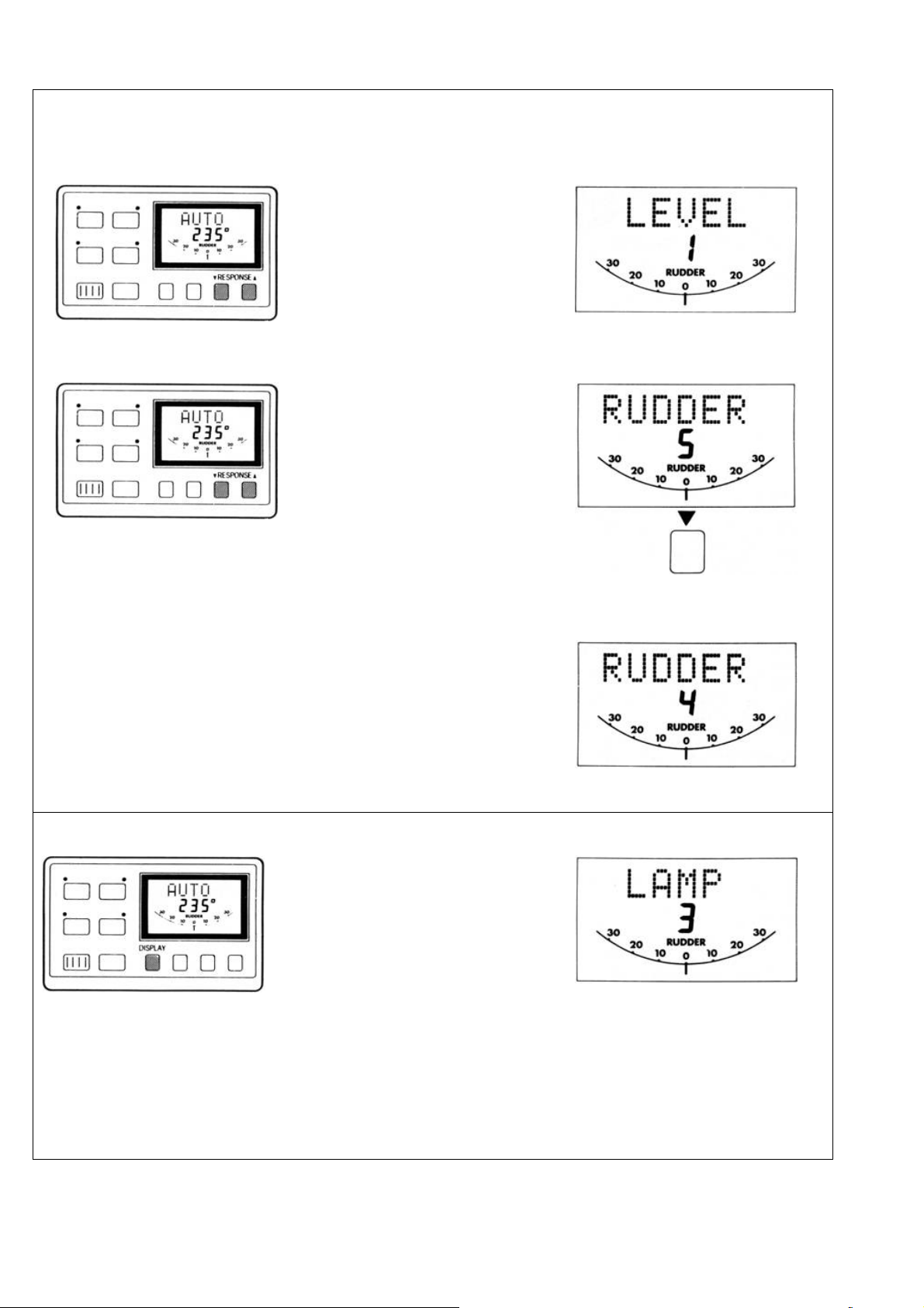
Response
Response Level Adjustment (see Operating Hints)
Push to increase (▲) or decrease
(▼) response level
To display response level without
changing it push both Response
keys together briefly.
Rudder Gain Adjustment (see Operating Hints)
Push and hold down for 1 second
both Response keys together to
display rudder gain level.
Response Level
Rudder Gain Level
Within 10 seconds push once to
increase (▲) or decrease (▼)
rudder gain.
(Response and Rudder levels are displayed for 10 seconds only)
Illumination
(illumination level is displayed for 10 seconds only)
4
Push and hold down Display for 1
second to switch on illumination.
Within 10 seconds push
Display to select illumination level.
Rudder Gain Level
Illumination Level
3 = High
2 = Medium
1 = Low
OFF = OFF
Page 7

3. Additional Displays
Display Auto Mode
The Display pushbutton is used to cycle through
additional information menus. These menus depend on
the autopilot mode and if navigation information is
available.
Standby Mode
• Main Display
• Main Display
• Navigation Displays
•
• Navigation Displays
•
See section on Navigation Displays.
See section on Navigation Displays
• Watch Alarm
5
Page 8

Track Mode Navigation Displays
• Main Display
• Navigation Displays
See section on Navigation Displays.
With the Navigation Receiver operating in waypoint
mode, the following information can be displayed
(provided that the Navigation Receiver transmits the
appropriate information - see Installation Handbook).
• Cross Track Error
The arrows show the direction to steer to rejoin the
desired Track:
► Starboard
◄ Port
• Bearing to Waypoint
• Watch Alarm
Magnetic
or
True
• Distance to Waypoint
6
Page 9

• Waypoint Number
Watch Alarm (not available in Standby)
• Engage the Autopilot in Auto/Track/Windvane mode.
• To select Watch alarm push Display repeatedly
until Watch appears.
The 4 minute timer is now running:-
- After 3 minutes 'Watch' flashes on all
control units.
- After 4 minutes the alarm sounds on all
control units.
• Push Auto at any time to reset the timer to 4
minutes and silence the alarm.
• To cancel the Watch alarm at any time push
Display.
7
Page 10

Warning Messages
• Off Course Alarm
- Sounds if the vessel deviates from the automatic
heading by more than the selected amount for over 20
seconds.
• Low Battery Alarm
- Sounds if the course computer supply voltage falls
below 11 volts for over 20 seconds.
• Track Mode Alarms
- Sounds if the cross track error exceeds 0.30nm
- Sounds when the target waypoint number
changes.The displayed bearing is to the new
waypoint. PORT or STBD indicates in which
direction the autopilot will turn onto the new
waypoint bearing
- Push Track to silence the alarm and automatically
steer onto the new bearing to waypoint.
• Manual Override Alarm
(Installations with stern drive actuators only).
- Sounds it no waypoint data is received from the
Radio Navigation System for over 20 seconds.
- Sounds if the data has the incorrect format or if an
invalid flag is set.
8
- Sounds for 10 seconds when the autopilot is
manually overridden at the steering wheel. After 10
seconds the autopilot will return to Standby
automatically.
Note: Push Standby to silence an alarm and select
Standby mode (unless indicated otherwise).
Page 11

4. Additional Information for Sailing Vessels
Autotack
The ST7000 has a built in Autotack function which will
turn the vessel through 100 deg. This operates in both
compass and vane modes as follows:-
Vane
Note: It is important that the rudder angle transducer is accurately aligned
as the Autotack function mirrors standing helm and any offset will change
the initial tack angle.
Wind Trim
Wind Trim allows the autopilot to be supervised by
apparent wind direction. The wind direction is read
either:-
- From the SeaTalk bus (requires Autohelm ST50 wind)
OR
Automatic Heading
Push +1 and +10 keys together to
initiate a tack turning to Starboard.
Push -1 and -10 keys together to
initiate a tack turning to Port.
Push both red keys together to
select Wind Trim and maintain the
current apparent wind angle.
- Directly from a Masthead Transducer (Z080)
OR
- From an NMEA 0183 input on the control unit.
Previous Automatic Heading
Push and hold down for 1 second
both red keys together to return to
the previous apparent wind angle.
9
Page 12

Wind Change Alarm
Wind Trim uses the fluxgate compass as the primary
heading reference and automatically adjusts the
compass heading to maintain the original apparent wind
angle. If changes in apparent wind angle adjust the
original automatic heading by more than 15 deg. the
wind change alarm will sound.
- The alarm is silenced by pushing both red keys
together briefly.
Display of Wind Angle
If the wind angle information is supplied using the NMEA
0183 input or SeaTalk bus, the apparent wind angle and
tack sense (P & S) is added to the display menu and
accessed via the Display button.
Using Wind Trim
It is important to understand that "Wind Trim" prevents
over-reaction to gusts or sudden wind shifts. One
minute is required to change the heading in response to
a permanent change in apparent wind angle. Do not
attempt to override the automatic sequence with the
course change buttons.
In gusty conditions sail a few degrees off the wind and
pay frequent attention to sail trim and helm balance
using the rudder angle indication.
Performance will normally be improved by reefing
headsail and mainsail a liftle early rather than too late.
Apparent Wind Angle
• Adjust Apparent Wind Angle
10
Use the +1 or +10 degree buttons to
change heading and hence adjust
the apparent wind
Page 13

5. Operating Hints
Response Level Adjustment
The ST7000 has three response levels which enable
tighter course keeping to be achieved in certain cases:Level 1 - Automatic Sea State Control
Level 2 - Automatic Sea State Inhibit Level 3 - Automatic
Sea State Inhibit and counter rudder.
When the autopilot is switched on, the response level
is set to 1. This provides the best compromise between
power consumption and course keeping accuracy and is
suitable for nearly all situations.
Increasing Response level provides tighter course
keeping at the expense of increased power
consumption and general wear and tear. It is advisable
to use the minimum response level necessary to
achieve the desired course keeping accuracy. On
larger power vessels level 3 can improve slow speed
steering where the natural yaw damping of the vessel is
reduced.
Note: Level 3 is not recommended for use at planing
speeds or in rough seas.
Track
To make full use of Track control the following simple
points should be observed:-
• Always steer the vessel to within 0.1 nm of track and
bring the heading to within 5 deg. of the bearing to
the next waypoint before selecting Track.
• Always check that there are no navigational hazards
either side of the intended track.
• Always maintain an accurate log with regular plots
to verify the computed position read from the Radio
Navigation Receiver. Maintain a proper lookout at
all times.
Waypoint Advance
if the navigation receiver is transmitting the waypoint
number to the ST7000 the waypoint alarm will sound
whenever a new target waypoint is selected (see Page
8). When the alarm is sounding the ST7000 will
maintain the current heading and automatic track control
is suspended. Check the displayed new bearing to
waypoint and when it is safe to turn onto it, resume
automatic track control by simply
pushing Track. This accepts the new target waypoint
and will steer the vessel onto the new bearing to
waypoint.
The tidal offset may be very different on the new
bearing, and it is good practise to check the cross track
error after a couple of minutes. If the cross track error
continues to increase make a course adjustment of say
10 degrees in the direction of the arrow. This will help
the Track control correct more quickly for the new tidal
vector.
Automatic Trim
If Automatic Trim has been selected during calibration
the ST7000 will correct for trim changes. This correction
can take up to one minute to apply the rudder offset
necessary to restore the set automatic heading. Large
course changes which change the apparent wind
direction can produce large trim changes. In these
cases the autopilot will not immediately assume the new
autoitiatic heading, and only seftle onto course when the
Automatic Trim has been fully established.
To minimise the inherent time delay the following
procedure may be adopted for large course changes.
• Note required new heading.
• Select Standby and steer manually.
• Bring vessel onto new heading.
• Select Auto and let vessel settle onto course.
• Bring to final course with 1 deg. Increments.
It is sound seamanship to make major course changes
only whilst steering manually. In this way any
obstructions or other vessels may be cleared properly
and due account taken of the changed wind and sea
conditions on the new heading prior to engaging the
autopilot.
Rudder Gain
The rudder gain level selected during initial sea trials will
normally provide excellent steering performance over a
wide range of conditions. However, it may be noticed
that the autopilot tends to be a little less stable on
northerly headings in the higher latitudes of the Northern
hemisphere (and conversely southerly headings in the
Southern hemisphere). This is caused by the increasing
angle of dip of the earth's
11
Page 14

magnetic field at higher latitudes which has the effect of
amplifying rudder response on northerly (southerly)
headings.
Rudder Gain Adjustment (Sail)
It is not normally necessary to adjust the autopilot gain
setting once the correct level has been established
during initial sea trials.
Depending on the yacht's individual steering
characteristics a change of one level may improve
course keeping accuracy when going from northerly to
southerly (increase) or southerly to northerly (decrease)
headings.
The effect may be judged by carrying out a sea trial in
smooth water conditions and observing the results.
Note: The effect is reversed for the Southern
hemisphere.
Rudder Gain Adjustment (Powercraft) The tendency
towards northerly (southerly) heading instability is more
obvious in high speed craft and can be corrected by a
reduction in the rudder gain sefting. At speeds in
excess of 30 knots a reduction of two levels can be
required on headings between 315 deg. and 045 deg
(Northern hemisphere) or 135 deg. and 230 deg.
(Southern hemisphere).
Two options are available to control this:-
• Manual (Low speed and displacement craft). The
rudder gain control may change by one level when
going from northerly to southerly (increase) or
southerly to northerly (decrease) headings. The
effect may be judged by carrying out a sea trial in
smooth water conditions and observing the results.
Note: The effect is reversed for the Southern
hemisphere.
• Autoadapt (High speed planing craft)
The ST7000 can be set automatically to reduce the
effects of northerly heading instability. This feature is
selected in calibration mode by entering the latitude (see
Installation Handbook, Calibration, section on 'Auto
Adapt'). When selected the ST7000 automatically
adjusts the Rudder Gain depending on the compass
heading, removing the need for manual adjustment.
12
Rudder Gain/Speed Adjustment (Powercraft) High
speed planing craft exhibit very different steering
characteristics when on and off the plane. As a result it
is generally necessary to adjust the Rudder Gain setting
when going from displacement speed to planing speed
or vice versa.
Two options are available to achieve this:
• Automatic
When the ST7000 is used with an Autohelm S150
Speed Instrument or Tridata, Rudder Gain is
adjusted automatically with boat speed. There
should be no geed for any manual adjustment.
• Manual (No ST50 Speed/-Fridata)
The Rudder Gain setting may be increased by one or
two levels when dropping from planing speed to cruise
speed and decreased by the same amount when
returning to planing speeds.
Note: It is important to make the gain adjustment after
dropping to displacement speed and before returning to
planing speed.
Note: The adjustment of Gain with boat speed is
normally only required for high speed planing
powercraft.
Unsatisfactory Steering Performance
If the ST7000 has been installed and set up in
accordance with the instructions in the Installation
Manual it will provide excellent steering performance
over a wide range of conditions.
It performance drops but the autopilot is still working
correctly, the following simple checks should find the
fault:-
• Has a magnetic influence been introduced near the
fluxgate compass? i.e. anchor, chain, radio
equipment, loudspeaker, tools, generator etc.
Check that the autopilot compass heading still
corresponds with the steering compass.
• Are all fuses intact, circuit breakers engaged?
• Are all screw connections tight and free of
corrosion?
Page 15

• If the autopilot fails to hold course check the Rudder
Gain level. Has it been changed from the initial sea
trials level (check in Installation Manual)?
• If the vessel wanders check that the Rudder
Reference Transducer linkage is secure with no free
play.
Hydraulic Drive Units only:-
• Check that all unions are tight and bleed system to
remove air.
Failure of Drive Unit to Disengage
The mechanical drive actuators of the ST7000 are
designed to 'Fail Safe' - When power is disconnected
the drive unit will disengage leaving the steering system
free for manual control.
When Standby is selected the actuator will disengage
leaving the steering free.
It is remotely possible that a fault could develop which
could cause the actuator to remain engaged even when
Standby is selected. If this happens:-
• DISCONNECT THE MAIN CIRCUIT BREAKER TO
THE AUTOPILOT - THE STEERING WILL
IMMEDIATELY BE FREE , or
• IN AN EMERGENCY THE ACTUATOR CLUTCH
CAN NORMALLY BE OVERRIDDEN BY TURNING
THE STEERING WHEEL HARD.
It is emphasised that this fault is extremely unlikely and
can be immediately corrected as described.
If preferred a separate Override switch can be fitted
close to the steering position which will break the
actuator clutch drive for
Emergency Use.
Stern Drive Actuator
Manual Override Option
When used with a stern drive actuator, the ST7000 can
be set up automatically to release the drive if the
steering wheel is turned in an emergency situation.
After releasing the drive unit the ST7000 will return to
Standby and sound the manual override alarm for 10
seconds.
This feature is selected during autopilot
calibration (see Installation Handbook).
Note: This feature is for use with a stern drive actuator
only.
Control Unit Display Adjustment
The control unit display is designed to provide good
legibility over a wide range of viewing angles. However,
it is recommended that wherever possible the control
unit is mounted so that the viewing angle is normal to
the lcd display when the helmsman is in the usual
steering position. If the control unit is mounted so that
the usual viewing position is at an angle to the lcd
display, the lcd contrast can be adjusted to improve
legibility.
• Push Display and Track together momentarily.
Push ▲ to increase, ▼ to decrease contrast level.
Continue until the display has optimum legibility when
viewed from the usual helming position. Push Display
and Track together momentarily to store the selected
contrast level.
Note: Increasing the contrast level will suit
installations where the instrument is normally viewed
from below.
13
Page 16

6. Maintenance
The autopilot is one of the most used and hardest
working items of equipment on board, and therefore
must receive its fair share of attention and routine
maintenance. The working parts of the drive system are
sealed and lubricated for life during manufacture and
therefore do not require servicing.
Regular inspection of the installation is recommended in
the following areas where applicable.
1. Check tension and alignment of the drive chain
(Rotary Drive) and lubricate with good quality
waterproof light grease.
2. Check that Hydraulic Steering systems are free
from leaks and trapped air. Bleed when necessary
to remove air from the system.
3. Check that all inter-connecting cable terminals are
fully tightened and corrosion free.
4. Check that external waterproof sockets are capped
when not in use and periodically spray with WD40
(or similar) to protect from corrosion.
5. Check that the heavy power supply cable
connections are tight and free from corrosion.
14
7. Safety
Passage making under autopilot can greatly
increase the pleasure of the voyage and ensure the
crew can relax. However, this can lead to a
dangerous lack of attention to basic seamanship.
The following rules should always be
observed:Maintain a permanent watch and check
regularly all round for other vessels and obstacles
to navigations. No matter how clear the sea may
appear a dangerous situation can develop rapidly.
• Maintain an accurate record of the vessel's
position either by use of a radio navigation receiver
or visual bearings.
• Maintain a continuous plot of position on a
current chart. Ensure the locked autopilot heading
steers you clear of all obstacles. Make proper
allowance for Tidal Set - the autopilot cannot!
• Even when your autopilot is locked to the
desired Track using a radio navigation receiver
maintain a log and a regular positional plot. Radio
navigation signals can produce significant errors
under some circumstances and the autopilot cannot
detect this situation.
• Ensure that all members of crew are familiar with
the procedures required to engage and disengage
the autopilot.
• When searoom is restricted a crew member
must be close to a control unit at all times if under
autopilot control.
• On Powercraft permanent watch should be
maintained at the steering station when at speed
with the autopilot engaged.
Your Autoheim ST7000 will add a new
dimension to your boating enjoyment. However, it is
the responsibility of the skipper to ensure the safety
of the vessel at all times by careful observance of
these basic rules.
Page 17

8. Fault Location Procedure
The ST7000 has been designed to achieve very high
standards of reliability combined with ease of servicing.
If a fault should appear, please double check that all
connections in the connector unit are sound and that the
heavy duty power connections are tight and free from
corrosion. If you are satisfied that all connections are
sound, the simple check procedure tabulated below will
assist you to locate the most likely fault area,
If the autopilot switches on but does not operate
correctly, check the rudder angle and heading displays
on the control unit. If these appear incorrect, double
check all connections from the course computer to the
compass and rudder reference transducers.
In the case of a sailing yacht fitted with a windvane
system, if a fault occurs only in vane mode then it is
likely that fault has developed
in the vane head or the interconnection system.
Since the course computer houses the majority of the
electronic control system there is a high probability that if
an electronic fault has occurred it will be located in this
area. The course computer unplugs easily from the
connector unit for servicing. (See Installation Manual).
Control Units are removed by undoing the two thumb
nuts (accessed from behind). Disconnect the cables by
rotating the locking rings anti-clockwise before
separating the connectors.
The faulty unit should be removed and returned to your
nearest service agent.
If ary difficulties arise, please consult Nautech's Product
Support Department in the UK or your own national
distributor who will also be able to provide expert
assistance.
15
Page 18

9. Warranty, After Sales Service
Limited Warranty
Nautech or its appointed Distributors or Service Centres
will, subject to the conditions below, rectify any failures in
this product due to faulty manufacture which become
apparent within twelve months of its purchase date.
Equipment used in the country of purchase should be
sent directly to the authorised Distributor for that country
or its appointed Service Centres. The product will then
be serviced free of charge and returned promptly direct
to the sender.
Equipment used outside the country of purchase can be
either:a. Returned to the Distributor or Dealer in whose
country the equipment was originally purchased - it
will then be serviced free of charge and promptly
returned direct to the sender,or
b. The product can be returned freight pre-paid to the
authorised Distributor or its appointed Service
Centres in the country in which the product is being
used. It will then be serviced and returned direct to
the sender on the basis that the Distributor or
Service Centre will supply any parts used free of
charge but the sender will be invoiced for the
necessary labour and return shipment at the local
rate.
Conditions
The warranty is invalid if:a. The product has been misused, installed or
operated not in accordance with the standards
defined in this manual.
b. Repairs have been attempted by persons other
than Nautech approved Service personnel.
Full International Warranty
Nautech or its appointed Distributors or Service Centres
will, subject to the conditions below, rectify any failures in
this product due to faulty manufacture which become
apparent within twelve months of its purchase date
wherever the vessel and the product may be operated.
Conditions
1. The product must be installed aboard the vessel in the
country of purchase.
2. The product must be installed in accordance with the
recommendations issued by Nautech Ltd.
3. The installation must be carried out by an installer
approved by Nautech: alternatively, the installation must
have been inspected and approved by Nautech or its
approved installer.
4. The Warranty Registration Card must be completed
by:-
- The owner or user.
- The dealer supplying the product.
- The installer.
5. The Full International Warranty is invalid if:-
(a) The product has been misused, or installed or
operated not in accordance with standards defined
in this handbook.
(b) Repairs have been attempted by persons
other than Nautech approved Service personnel.
(c) The warranty card has not been completed
correctly or is not accompanied by proof of
purchase.
Claim Procedure
1. The product should be sent direct to Nautech or its
appointed Distributor or Service Centre nearest to
the vessel. The completed Warranty Card and
proof of purchase must accompany the claim. The
product will then be serviced free of charge and
returned promptly direct to the sender.
2. Nautech, its Distributors and Service Centres, are
not liable for any charges arising from visits to the
vessel not to attend to the product, whether under
warranty or not, nor for sea trials or any other work
associated with the installation, The right is
reserved to charge for any such services at the
local rate.
After Sales Service
Your ST7000 is designed to give you long service and
reliable performance wherever you sail. To ensure that
you can always receive prompt and expert attention in
case of any difficulty, Nautech has established a
worldwide network of Autohelm Service Centres.
Please contact your nearest Service Centre for
assistance. Always have ready:-
- Your warranty card.
- Proof of purch
16
44318/5
Page 19

Page 20

Raymarine Ltd.
Anchorage Park, Portsmouth
Hampshire, P03 5TD, UK.
Telephone +44 (23) 92 693611
Fax +44 (23) 92 694642
www.raymarine.com
 Loading...