

Page 1

ST60 Tridata
Instrument
Owner’s
Handbook
Document number: 81040-4
Date:10 November 2002
Page 2

Raymarine, ST60and SeaTalk aretrademarks ofRaymarine Limited
© Handbook contents copyright Raymarine Limited 2002
Page 3
i
Important information
Safety notices
WARNING: Product installation & operation
This equipmentmust beinstalled and operated in accordance with
theRaymarine instructionsprovided.Failureto doso couldresultin
personal injury,damage toyour boat and/or poor product
performance.
WARNING: Electrical safety
Make sure you haveswitched offthe power supply before youstart
installing this product.
WARNING:
Although we have designedthis productto be accurate and reliable,
many factorscan affect its performance. Therefore, it shouldserve
only as anaid to navigation and should neverreplace commonsense
and navigational judgement. Always maintain apermanent watch
so you canrespond to situations as they develop.
EMC conformance
All Raymarineequipment and accessories are designed tothe best
industry standards foruse in the recreational marineenvironment.
The designand manufacture of Raymarineequipment and accessories
conform to the appropriate Electromagnetic Compatibility (EMC)
standards, but correctinstallation is required to ensure that performance
is notcompromised.
Handbook information
Tothe best of our knowledge,the information in this handbookwas
correct whenit went topress. However,Raymarine cannot accept
liability forany inaccuracies oromissions it maycontain.
In addition, our policy of continuous productimprovement may change
specifications withoutnotice. Therefore, Raymarine cannot accept
liability for anydifferences betweenthe product and the handbook.
Page 4

ii ST60 Tridata Instrument Owner’s Manual
Page 5

iii
Contents
Important information ..........................................................................................i
Safety notices ................................................................................. i
EMC conformance ........................................................................i
Handbook information .................................................................. i
Introduction ......................................................................................................... vii
Data inputs ..................................................................................vii
SeaTalk ....................................................................................... vii
Stand alone operation.................................................................viii
Remote control ..........................................................................viii
Mounting options.......................................................................viii
Parts supplied ............................................................................... ix
Chapter 1: Operation .........................................................................................1
1.1 Gettingstarted ...............................................................................1
Displayed information ..................................................................1
1.2 Normaloperation .......................................................................... 1
Depth ............................................................................................ 2
Current depth display ..............................................................2
Depth alarmthreshold displays ...............................................3
Speed ............................................................................................ 3
Boat speed ............................................................................... 3
Maximum speed .....................................................................4
Average speed ......................................................................... 4
Velocity made good (to windward) ......................................... 4
Trip ................................................................................................ 5
Log .......................................................................................... 5
Trip screen ............................................................................... 6
Water temperature ...................................................................6
Timers ..................................................................................... 6
1.3 Alarms ..........................................................................................7
1.4 Display settings ............................................................................. 7
Illumination .................................................................................. 7
Contrast .........................................................................................8
1.5 Remote control ............................................................................. 8
Chapter 2: Maintenance and Faultfinding ......................................................9
2.1 Maintenance .................................................................................9
Servicing andsafety ...................................................................... 9
Instrument ..................................................................................... 9
Transducers ................................................................................... 9
Cabling ........................................................................................ 10
Page 6

iv ST60 Tridata Instrument Owner’s Manual
2.2 Faultfinding ................................................................................ 10
Preliminary procedures ...............................................................10
Fixing faults ................................................................................ 10
Technical support ........................................................................11
World wide web .................................................................... 11
Telephone help line ............................................................... 11
Help usto help you ................................................................12
Chapter 3: Installation .....................................................................................13
3.1 Planningyour installation ........................................................... 13
Site requirements ........................................................................ 13
Transducers ...........................................................................13
Instrument ............................................................................. 15
EMC InstallationGuidelines ......................................................16
Suppression Ferrites ..............................................................17
Connections to Other Equipment ..........................................17
3.2 Procedures ..................................................................................18
Unpacking ...................................................................................18
Fitting theinstrument .................................................................. 18
Surface mounting .................................................................. 18
Flush mounting ..................................................................... 19
Bracket mounting ..................................................................22
Fitting transducer ........................................................................23
Running transducer cable ......................................................23
Connecting the instrument ..........................................................24
Types of connection ..............................................................24
Signal connections ................................................................24
Power supplyconnections ....................................................25
Chapter 4: Calibration .....................................................................................27
4.1 Introduction ................................................................................27
Speed readings ............................................................................27
EMC conformance...................................................................... 27
4.2 Usercalibration ...........................................................................27
Depth ........................................................................................... 29
Depth units ............................................................................29
Depth offset ...........................................................................29
Shallow alarmlock ............................................................... 30
Speed ........................................................................................... 31
Set speedunits ....................................................................... 31
Set speedresolution ..............................................................31
Set logunits ........................................................................... 31
Setting thecorrect speed .......................................................31
Adjust toSOG .......................................................................33
Page 7

v
Set temperatureunits ............................................................ 33
Temperature calibration ........................................................ 33
Timer alarm buzzer ...............................................................33
Leaving Usercalibration ............................................................. 33
4.3 Intermediate calibration ..............................................................34
Speed calibration ........................................................................35
Leaving Intermediatecalibration ................................................39
4.4 Dealer calibration ....................................................................... 39
User calibrationon/off ................................................................39
Response settings ........................................................................ 39
Boat showmode ..........................................................................41
Factory defaults ..........................................................................41
Leaving Dealercalibration ......................................................... 41
Page 8

vi ST60 Tridata Instrument Owner’s Manual
Page 9
vii
Introduction
Thank youfor purchasing a Raymarine product.We are sure yourST60
instrument will giveyou many years oftrouble-free operation.
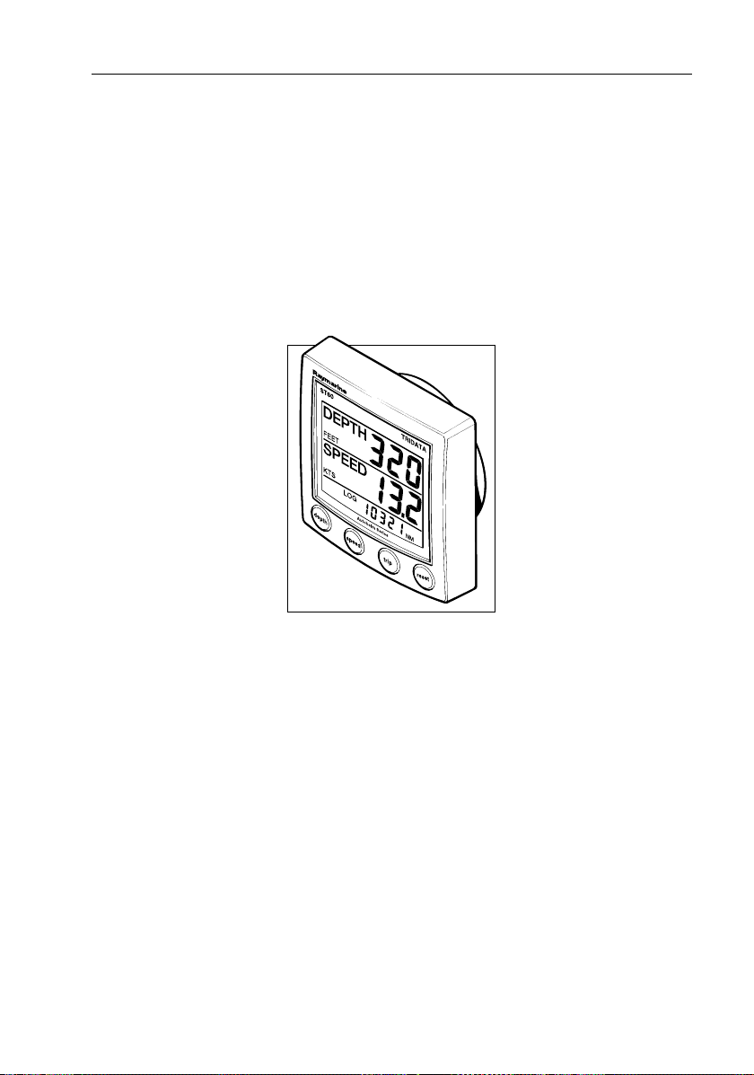
This handbook describeshow to install anduse the Raymarine ST60
Tridata instrument. Thisinstrument provides accuratedepth, speed, trip
and timer information, on ahigh quality Liquid Crystal Display (LCD).
The instrument is constructed in arugged weather-proofedcase to provide reliable performance,even under the most demanding conditions.
Data inputs
The ST60Tridata instrument can fulfil master and/orrepeater roles by
receiving data either from the appropriate transducers and/or from a
SeaTalk instrumentation system.
SeaTalk
SeaTalk enables a number of compatible instruments to operate asa
single, integrated navigationalsystem. Instrumentsin a SeaTalk system
are linkedby means ofa single cable, which feeds both power and data.
Instruments can thereforebe added to thesystem by plugging them into
the network.SeaTalk isflexible enough to adaptto any numberof
compatible instrumentswithout requiring acentral processor. SeaTalk
can alsocommunicate viaan interface, withnon-SeaTalk equipment
using theinternationally-accepted NationalMarine Electronics
Association (NMEA) protocol.
D4324-1
Page 10

viii ST60 Tridata Instrument Owner’s Manual
In a SeaTalk system,each instrument can be either a master ordedicated
repeater unit.A master instrumentis directly connectedto a transducer
(the device thatprovides the raw data),and provides data andcontrol for
the service itis providing,to allother equipment on the SeaTalk network.
A slave instrument is not directly connected to atransducer but repeats
information provided byother equipment in the SeaTalk network.
Stand alone operation
In Stand alone operation,the ST60 Tridatainstrument is connected only
to the relevant transducer and doesnot display information from, or
provide information to, anyother instruments.
Remote control
When connectedto SeaTalk,the ST60 Tridata instrument canbe
controlled remotelyby a SeaTalkRemote Keypad Unit,to provide
instant remoteaccess to the variousdisplay readouts.
Mounting options
If you donot want to surface mount your ST60 instrument, optionsare
available for:
• Flushmounting. If you have orderedthe flushmounting option alowprofile bezel and four fixing screwsare also provided.
• Bracket mounting.
Page 11

ix
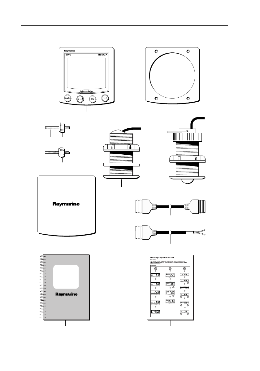
Parts supplied
Unpack your ST60instrument and check thatthe following items are
present:
• Item 1, ST60 Tridata instrument fitted with standard bezel for
surface mounting.
• Item2, Fixingstuds (2).
• Item 3, Thumb nuts(2).
•Item4,Gasket.
• Item 5, Depth transducer.
• Item 6, Speed transducer,plus bung (not illustrated).
• Item 7, SeaTalk interconnectioncable.
• Item 8, Power cable.
• Item 9, Instrument Cover.
• Item 10, Owner’sHandbook. A Warranty documentand fitting
templates are includedin this Handbook.
•Item11,CueCard.
Spare spadeterminals are alsoprovided, to re-terminate thetransducer
cable ifit hasto be cut to facilitate installation.
Note:The above packing list is for an ST60 Tridata system. Where an
instrument is purchased separately, Speed and D epth transducers are
not included.
Page 12
x ST60 Tridata Instrument Owner’s Manual
32
32
9
ST60
Tridata
Instrument
Owner's
Handbook
1
4
6
5
7
8
TRIDATA
trip
speed
depth
Current
Boat speed
Maximum
speed
Average speed
VMG to
windward
Log
Trip
reset
3s
to Reset
Water
temperature
reset
3s
to Reset
Count-up timer
reset
reset
reset
3s
to Reset
3s
to Reset
Start/Stop
10 minute
race start time
reset reset
3s
to Reset
Start/Stop
5 minute
race start timer
reset reset
3s
to Reset
Start/Stop
depth
Shallow Alarm
Threshold
Deep
alarm threshold
Anchor shallow
alarm threshold
Anchor deep
alarm threshold
1110
D4441-4
Page 13
Chapter 1: Operation 1
Chapter 1: Operation
1.1 Getting started
This handbook describeshow to operate, maintainand install the
Raymarine ST60 Tridata instrument.
CAUTION:Calibration requirement
The ST60Tridata instrument is calibrated to factory (default)
settings when firstinstalled and must therefore be calibrated before
use, inaccordance withthe procedures inChapter 4,Calibration,to
ensure optimum performance on your vessel.
Do NOT use theinstrument until the calibrationprocedures have
been satisfactorily completed.
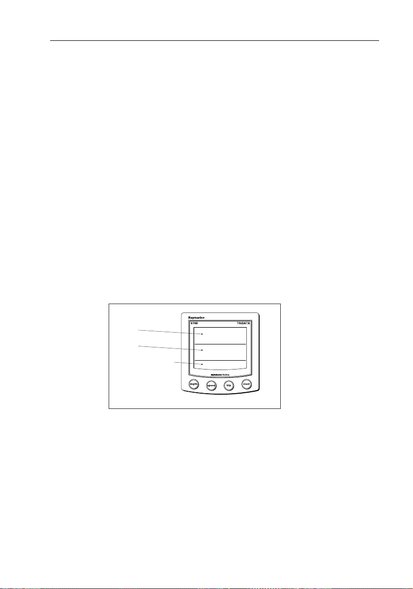
Displayed information
The ST60Tridata instrumentscreen is divided into three separate areas,
each of which displaysa separate type ofinformation,as shownin the
following illustration.
Depth
Speed
Trip, log, water
temperature & timer
Screen layout
1.2 Normal operation
Use theflow charts in this Chapterto operate your ST60 Tridata
instrument. Flow chartsare provided for:
•Usingthe
Onmaster instruments,this alsogives accessto depthalarm threshold
information, and allowsyou to set the alarmthresholds.
•Usingthe
speed andVelocityMade Good (VMG) to windward.
depth key. This gives accessto current depth information.
speed key. This givesaccess to maximumspeed, average
D4424-2
Page 14
2 ST60 Tridata Instrument Owner’s Manual
•Usingthetrip keyto gain accessto log, trip, water temperature and
timer information.
All keypresses are momentary unlessotherwise stated.
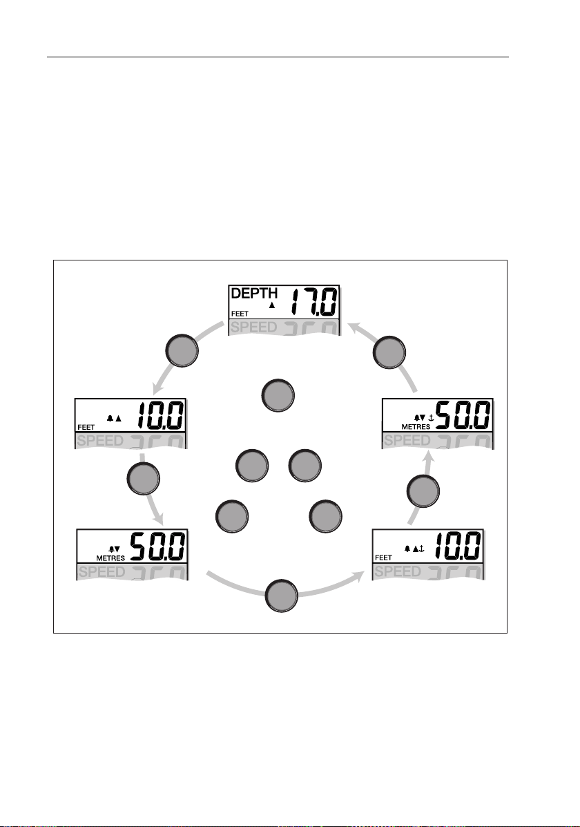
Depth
Use thedepth key to selectthe required information, asshown in the
Using the depth key illustration. The depth measurement units are either
feet ormetres, as selected during user calibration (see Chapter 4,
Calibration).
Current depth
Shallow
alarm threshold
depth
Deep
alarm threshold
Using the depth key
Current depth display
The current depth screen shows thetitle DEPTH, the selected depthunits
and the depthmeasurement. It also showsa depth trend indicator, which
is either an up arrowto show seabed rising or a down arrowto show
seabedfalling.
depth
To enable/disable any alarm
for 2 seconds
reset
Press
To enter and exit alarm adjust mode
Press
trip
In adjust mode, use
trip
to decrease or
(toggle action)
reset
and together
reset
depth
to increase
depth
Anchor deep
alarm threshold
depth
Anchor shallow
alarm threshold
D4413-1
Page 15

Chapter 1: Operation 3
If forany reason depth information is lost, the DEPTH title will flash once
per secondand the displayed depth valuewill be the lastgood reading.
Depth alarm threshold displays
The alarmthreshold displays areavailable if the instrument is operating
as a master.Each displayis identifiedby thepresence ofan alarmsymbol
( )and eitheran uparrow for ashallow alarm or a down arrow for a deep
alarm. The shallow anddeep anchoralarms areidentified by means of an
additional anchor icon.
You canenable and disableindividual alarmthresholds by pressing the
reset key for 2 seconds, whilethe relevant alarm threshold is displayed.
Each alarmthreshold is displayedfor a nominal 7seconds, and ifno
action is taken during that time, the display will timeout to the current
depth display.
Adjusting alarm thresholds
Toadjust the alarm threshold levels, press the
simultaneously to enteradjust mode, then use either the
decrease) orthe
have setthe requiredvalue,pressthe
alarm settingand exit theadjust mode.
reset key (to increase) the threshold value. When you
tripand reset keysagain, to savethe
trip andreset keys
trip key (to
Note:Adjustment of the shallow alarm threshold can be disabled duri ng
calibration. When adjustment is di sabled, you cannot enter adjust mode.
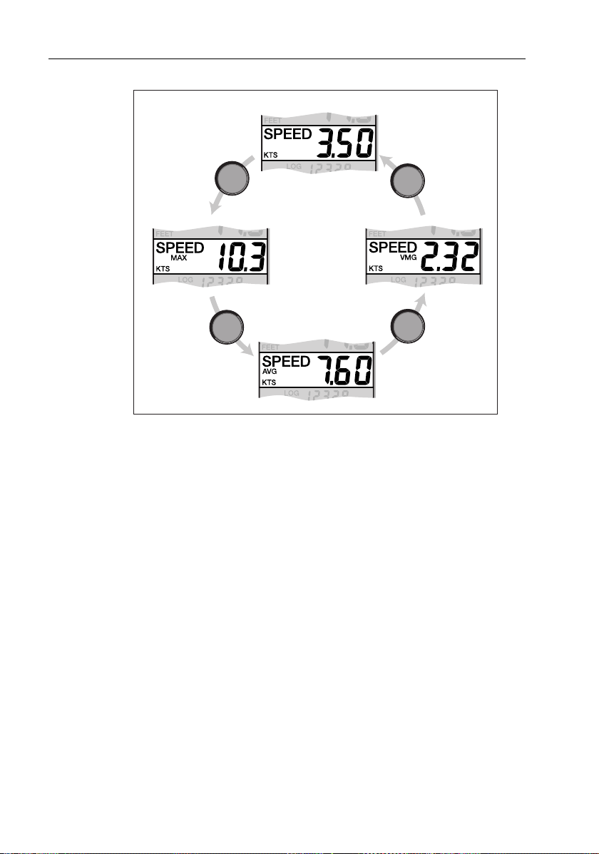
Speed
Use the speed keyto select the requiredinformation, as shown in the
Using the speed key illustration. The speed measurement units areeither
knots (KTS), milesper hour (MPH) orkilometres per hour (KMH),as
selected during usercalibration (see Chapter 4, Calibration).
The maximumspeed, average speed andVMG to windward are each
displayed for anominal 7 seconds, and if no action istaken during that
time, the display will timeout tothe Boat speed display.
Boat speed
Shows thecurrent speed and selected speed units.
Page 16
4 ST60 Tridata Instrument Owner’s Manual
Boat speed
speed
Maximum
speed
speed
Using the speed key
Average speed
speed
speed
VMG to
windward
D4414-1
Maximum speed
The screen shows the maximumspeed attained sincethe lastreset.
The maximum speed value is resetautomatically at power-up. If the
instrument is operating as a master, the maximum speed canalso bereset
manually by pressing the
reset key for 2 seconds.
Average speed
The screen shows the averagespeed since the last reset.
The averagespeed value is resetautomatically at power-up. If the
instrument isoperating as a master, the average speedcan also bereset
manually by pressing the
reset key for 2 seconds.
Velocity made good (to windward)
Velocity made good (VMG) information isavailable if your instrument is
partof aSeaTalksystemto whicha SeaTalk-compatiblewind instrument
is alsoconnected.
Page 17
Chapter 1: Operation 5
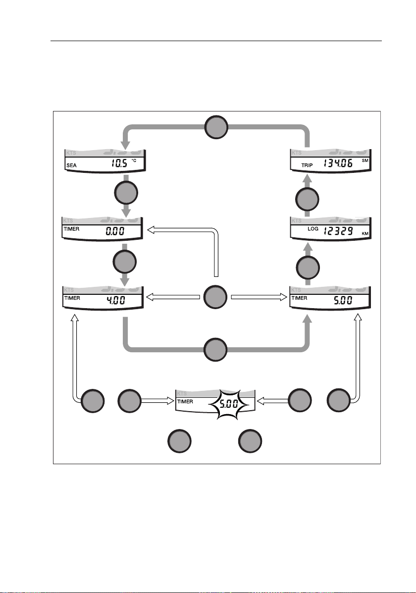
Trip
The trip key gives accessto log, trip,water temperature andtimer
displays, as shown inthe Using the trip key illustration.
trip
Water
temperature
Trip
Count-up
timer
Race start
timer 1
To enter/leave
adjust mode, press
trip
and
momentarily
Using the trip key
Log
trip
trip
reset
Press
reset
to start timer, or for lap time (when running)
To set a different race start timer value, press
to decrease the value
either momentarily
or for 1 s to reset timer to start value.
trip
trip
reset
to increase the value
trip
trip
To enter/leave
adjust mode, press
and
momentarily
reset
trip
Log
Race start
timer 2
D4415-2
The Log screen shows the total distance covered by the vessel since the
instrument was fitted.
Page 18

6 ST60 Tridata Instrument Owner’s Manual
Trip screen
The tripscreen shows the distancecovered sincethe trip valuewas last
reset.
The trip value is reset automatically at power-up, and if theinstrument is
operating as a master, the tripvalue canalso be reset manually by
pressing the
reset key for 3seconds.
Water temperature
The watertemperature is shownin either degreesCelsius (°C)or
Fahrenheit (°F), asset during calibration (see Chapter 4, Calibration).
Timers
The count-up timer and tothe two race-start timer times areeither in
seconds (S) or minutes (M), depending on thecounter values.
Refer tothe Using the trip keyflow diagram to display the required timer.
Once you havedone this, press the reset key to start thetimer running.
When atimer is running,the delimiter (i.e.‘.’or ‘:’) flashes.For lap
timing, press the reset key. To stop andreset a timerto the startvalue,
hold down the reset key for 1 second.
Once a timer is running, you can leave the timer pageand selectany other
display. Thecounter will continue torun in the background.
Race-start timers
You canset each race-start timerto any whole-minutevalue from 1 to 15
minutes.
Note: Whe n the instrument is first instal led, the race-st art timers are s et
to 4 and 5 minutes respectively.
To set a race-starttimer:
1. Use thetrip keyas shown inthe Using trip key flow diagramto select
the requiredrace-start timer.
2. Simultaneouslypress the trip andreset keys to enter the race-start
timeradjust mode.
3. Use either the tripor reset key to set the required value.
4. Simultaneouslypress the trip andreset keys to save the value and
leave the race-start timer adjust mode.
Page 19

Chapter 1: Operation 7
If youare using one ofthe race-start timers andthe timerbuzzer is
enabled, thebuzzer will:
• Double-beep every minute.
• Beep three timesat the startof the last30 seconds.
• Beep once for each of the last10 seconds.
• Beep for 2 seconds atzero.
The timerbuzzer is enabledor disabled aspart of thecalibration
procedure (see Chapter 4, Calibr ation).
Note:After a race-start timer has counted-down to zero, it will then start
counting up.
1.3 Alarms
An alarmcondition occurs if:
• The depth is less than the SHALLOWor SHALLOW anchorthreshold.
• The depth isgreater than theDEEP anchor threshold.
• The depth crosses the DEEPthreshold.
An alarmcondition is indicated by analarm buzzer anda flashing alarm
symbol ( ) on the display. SHALLOW or DEEP alarmsare indicated byup
and downarrows respectively,and for anchor alarmsan anchor symbol
( ) is displayed.
When theinstrument is operating as amaster, youcan check thealarm
thresholds and ifnecessary set them up,as detailed under Normal
operation - Depth.If an alarm isnot enabled, the associateddisplay
shows an OFF legend.
1.4 Display settings
Illumination
When theinstrument is first powered up, the display illumination is set to
its lowest (courtesy) level, to facilitate initial access to the keys.
To adjust thelevel of display illumination:
1. Hold down the
illumination-adjust mode.
2. There are four presetillumination levels. Use the
through theselevels until you reachthe level you want.
depth key for approximately one second, toenter the
depth keytocycle
Page 20

8 ST60 Tridata Instrument Owner’s Manual
3. Press any other keyto leave the illumination-adjust mode.
Note: The displ ay will also return to normal operation 7 seconds after
the last key press.
Contrast
To adjust the display contrast:
1. Holddown the
contrast-adjust mode.
2. There are fourpreset contrastsettings. Use the
through these settings until you achieve optimum display quality.
3. Press any other keyto leave the contrast-adjust mode.
Note: The displ ay will also return to normal operation 7 seconds after
the last key press.
1.5 Remote control
When itis connected toSeaTalk, the ST60 Tridata instrument canbe
controlled remotelywith a SeaTalk Remote Keypad Unit. Remote
control ofan instrument is indicated by a REMOTE legend on thedisplay,
to indicate that the keypad hascontrol.
Details on howto use the remote control facility can befound in the
SeaT alk Remote Keypad Owner’s Handbook.
depthkey forapproximately twoseconds, toenter the
depth keytocycle
Page 21

Chapter 2: Maintenance and Faultfinding 9
Chapter 2: Maintenance and Faultfinding
2.1 Maintenance
Servicing and safety
• Raymarine equipmentshould beserviced onlyby authorised Raymarine service technicians. They willensure thatservicing procedures
and replacementparts used will not affectperformance. There are no
user-serviceable parts inany Raymarine product.
• Some products generate highvoltages, and so never handlethe
cables/connectors when power is being applied tothe equipment.
• When powered up,all electrical equipmentproduces electromagnetic fields.These can cause adjacent pieces ofelectrical equipment
to interactwith oneanother,with aconsequent adverse effecton operation. In order to minimise theseeffects and enable youto getthe best
possible performance from your Raymarine equipment, guidelines
are given in theinstallation instructions, toenable you to ensureminimum interactionbetween different itemsof equipment, i.e. ensure
optimum Electromagnetic Compatibility (EMC).
• Always report any EMC-relatedproblem to your nearest Raymarine
dealer.We usesuch information toimprove ourquality standards.
• In someinstallations, it maynot bepossible to prevent theequipment
from beingaffected by external influences.In general thiswill not
damage the equipmentbut it can leadto spurious resetting action, or
momentarily may resultin faulty operation.
Instrument
Certain atmospheric conditionsmay cause condensation toform on the
instrument window. Thiswill not harmthe instrument andcan becleared
by increasing theillumination setting toLevel 3.
Periodically clean your ST60instrumentwitha softdamp cloth.Do NOT
use chemical and abrasive materials to clean the instrument.
Transducers
Refer tothe Installation and Maintenance instructions suppliedwith the
transducers.
Page 22

10 ST60 Tridata Instrument Owner’s Manual
Cabling
Examine all cables forchafing or other damage to theouter shield and,
where necessary, replaceand re-secure.
2.2 Fault finding
Preliminary procedures
Changes in the electronic environment mayadversely affect the operation ofyour ST60 equipment. Typical examplesof such changes are:
• Electrical equipmenthas recently beeninstalled or movedaboard
your vessel.
• Youare inthe vicinityofanother vessel or shorestation emitting radio
signals.
If you appearto have a problem,first ensure that theEMC requirements
(see Chapter3, Installation) are still being met before further
investigating the problem.
Fixing faults
All Raymarine products are subjected to comprehensive testand quality
assurance programmesprior topacking andshipping. However, if a fault
occurs, the followingtable may help toidentify and rectify the problem.
Fault Cause Remedy
Instrument display blan k. No power supply. Check power supply.
Check SeaTalk cabling and connector
security.
Check fuse/circuit breaker.
No speed or temp erature
information.
No speed information.
No exc han ge o f inf orm ation between SeaTalk
instruments
Speed transducer
cabling problem.
Speed transducer
paddle wheel fouled
SeaTalk cabling
problem.
Check cabling and security of
transducer connections.
Clean paddle wheel.
See CAUTION below.
Check the security of SeaTalk
connectors.
Disconnect instruments one by one, to
isolate faulty unit
Page 23

Chapter 2: Maintenance and Faultfinding 11
Fault Cause Remedy
Failure of group of
instruments in SeaTalk
chain.
LAST flashes or dashes
displayed continuously
(depth greater than 3 feet).
LAST flashes while under
way.
SeaTalk cabling or
connector problem.
Depth transducer or
connection problem.
Aerated water
Boat wake
Prop wash etc
Check the security of SeaTalk
connections between functioning and
non-functioning instruments.
Check depth transducer cable and
security of transducer connections.
Ensure readings stabilise when clear of
disturbed water.
CAUTION:
If youneed to remove the Speed transducer insert, havethe
transducer bung to hand and secure it in thetransducer body
immediately after the inserthas been removed, to prevent excessive
ingress of water.
Technical support
Raymarine provides acomprehensive customer support service, onthe
world wideweb and bytelephone help line. Please use either ofthese
facilities if you areunable to rectify a problem.
World wide web
Please visit the CustomerSupport area of our website at:
www.raymarine.com
As well as providing a comprehensive Frequently AskedQuestions
section and servicing information, it also givese-mail access to the
Raymarine Technical Support Departmentand a details of the locations
of Raymarine agents,worldwide.
Telephone help line
If youdo not have accessto the world wideweb, please call:
1-800-539-5539, extension 2444 or
(603) 881-5200 extension 2444
Page 24

12 ST60 Tridata Instrument Owner’s Manual
Help us to help you
When requesting service,please quote the following product
information:
• Equipment type.
• Model number.
• Serial number.
• Software issue number.
The Softwareissue number can beascertained by meansof the
Intermediate Calibration facility, see Chapter 4, Calibration.
Page 25

Chapter 3: Installation 13
Chapter 3: Installation
This chapterdescribes how toinstall the ST60Tridata instrument, and
associated Speedand Depthtransducers. Thetransducers arefitted in the
hull ofthe vessel and connected to the rearof the instrument.The actual
type oftransducers depends on the typeof hull in whichthey are to be
installed.
For advice, or further information regarding the installation of this
equipment, please contact the Raymarine Product Support Department
or your own National Distributor.
3.1 Planning your installation
Before starting the installation, spend some timeconsidering thebest
positions for bothtransducer and instrument, such thatthe Site
Requirements and the EMC Guidelines (below) aresatisfied.
Site requirements
Transducers
Speed
75 mm (2.94 in)
diameter
51 mm (2.0 in)
diameter
75 mm (2.94 in)
diameter
14 mm
(0.57 in)
100 mm
D4447-4
75 mm (2.94 in)
diameter
95 mm (3.75 in)
51 mm (2.0 in)
diameter
75 mm (2.94 in)
diameter
Depth
5 mm
(0.19 in)
The transducertypes required for the varioushull types are asfollows:
(3.95 in)
Page 26

14 ST60 Tridata Instrument Owner’s Manual
Hull material Speed transducer Depth transducer
Glass reinforced
plastic (GRP)
Steel M78712 Through hull plastic M78713 Through hull plastic or
Aluminium M78712 Through hull plastic M78713 Through hull plastic or
Wood M78716 Through hull bronze M78714 Through hull bronze or
M78712 Through hull plastic M78713 Through hull plastic or
M78718 Retractable through hull
M78718 Retractable through hull
M78718 Retractable through hull
M78719 Retractable through hull
bronze
Other transducer typesare also available for specificrequirements. For
further details, contact your local Raymarine dealer.
For accuratespeed and depth readingsthe transducers should be sited
within the clear water flow areas indicated by the shaded areas inthe
following diagram.
Sailing vessel
Planing power
vessel
Displacement power
vessel
Transducer siting
D4349-1
The transducers shouldalso:
• Be ahead ofthe propellers(by a minimum of 10% of thewater line
length).
• Be at least150 mm (6 in) awayfrom the keel (ideallyahead of the
keel ifa sailing yacht).
Page 27

Chapter 3: Installation 15
• Be as nearas possible tothe centre lineof the vessel.
• Be clear of otherthrough-hull fittingsor projections.
• Have sufficient clearance inside thehull to fit the nut.
• Have 100 mm (4 in) of headroom to allow for withdrawal.
In additionto the above requirements, thedepth transducer must be
mounted within 10
Maximum transducer angle
0
of thevertical, forward, aftand athwart ships.
10˚ maximum
D4350-3
Instrument
CAUTION:
The presenceof moistureat therear ofthe instrument could cause
damage either by entering the instrumentthrough the breathing
hole orby coming intocontact with theelectrical connectors.
ST60 instrumentscan be fittedeither above or belowdeck, provided the
rear ofthe instrument is sited whereit is protectedfrom contact with water.
Each instrumentmust also be positioned where:
• It is easilyread by thehelmsman
• It is protected against physical damage
• It is at least 230 mm (9 in) from a compass
• It is atleast 500 mm (20 in) from radio receiving equipment
• There is reasonablerear access forinstallation andservicing
Page 28

16 ST60 Tridata Instrument Owner’s Manual
With standard
bezel
diameter
90mm (3.54in)
115mm (4.53in)
With low
profile bezel
110mm (4.33in)
123mm (4.85in)
6.2mm
(0.25in)
24mm
(0.95in)
35mm
(1.4in)
15mm
(0.6in)
ST60 instrument dimensions
EMC Installation Guidelines
All Raymarineequipment and accessories are designed to the best
industry standards for usein the recreational marineenvironment.
Their design and manufacture conforms tothe appropriate
Electromagnetic Compatibility (EMC) standards,but correctinstallation
is required to ensure that performanceis not compromised. Although
every effort has been taken toensure that they will perform under all
conditions, it isimportant tounderstand what factors couldaffect the
operation of theproduct.
The guidelines given here describe theconditions foroptimum EMC
performance, but it is recognized that it may not be possibleto meetall of
these conditions in allsituations. To ensure the best possible conditions
for EMC performancewithin the constraints imposed by any location,
always ensure themaximum separationpossible betweendifferent items
of electricalequipment.
diameter
90mm (3.54in)
123mm (4.85in)
D5785-1
Page 29

Chapter 3: Installation 17
For optimum EMC performance, it isrecommended that wherever
possible:
• Raymarine equipment andcables connected toit are:
• At least 3ft (1 m) fromany equipment transmitting orcables carrying radio signals e.g. VHF radios, cables and antennas. Inthe
case of SSB radios, the distance shouldbe increased to 7 ft(2 m).
• More than 7 ft(2 m) from thepath of aradar beam. A radarbeam
can normally be assumed tospread 20 degreesabove and below
the radiatingelement.
• The equipment is supplied from a separate batteryfrom that used for
engine start. Voltage dropsbelow 10 V in thepower supply to our
products, and starter motor transients, can cause the equipment to
reset. This willnot damage the equipment, butmay cause the loss of
some information andmay change the operatingmode.
• Raymarine specified cablesare used. Cutting andrejoining these
cables cancompromise EMC performance andmust be avoided
unless doing so is detailed in the installation manual.
• If a suppression ferrite is attached to acable, thisferrite should notbe
removed. If theferrite needsto beremoved during installation it must
be reassembled inthe same position.
Suppression Ferrites
The following illustrationshows typical cable suppression ferritesused
with Raymarine equipment.Always use theferrites suppliedby
Raymarine.
D3548-2
Connections to Other Equipment
Ifyour Raymarineequipmentis tobeconnected tootherequipmentusing
a cablenot supplied by Raymarine, a suppression ferriteMUST always
be attachedto the cable near the Raymarineunit.
Page 30

18 ST60 Tridata Instrument Owner’s Manual
3.2 Procedures
As it is not possible to describeprocedures for all possible installation
scenarios, the procedures given heredescribe the broad requirements for
installing theSpeed and Depthtransducers and the ST60 Tridata
instrument. Adapt theseprocedures as appropriate, to suityour
individual requirement.
CAUTION:
Where itis necessary to cut holes (e.g.for cable routing and
instrument mounting), ensure thatthese will notcause ahazard by
weakening criticalparts of the vessel’s structure.
Unpacking
Unpack your ST60 equipment and checkthat the items describedin
Introductionare present.
Each ST60instrument is supplied witha standard bezelfor surface
mounting. Optional mounting kitsare available for flush mounting and
bracket mountingthe instrument.If you haveordered the flush mounting
option a low-profile bezel and four fixingscrews are also provided.
Fitting the instrument
The ST60 Tridata instrument can beinstalled usingone of a numberof
different mounting options:
• Surface mounting. Gives a profileof approximately 24 mm.
• Flush mounting. Gives a profile of approximately6 mm.
• Bracket mounting.
The ST60 instrumentscan also be mountedbehind a panel with just the
instrument dialand keys visible.
Surface mounting
To surface mount your ST60instrument (seethe S urface mounting
illustration):
1. Ensure that:
• The selected location is clean, smooth and flat.
• There is sufficientspace behind the selected location toaccommodate the rearof the instrument andconnectors.
Page 31

Chapter 3: Installation 19
11223455
Surface mounting
D4343-2
2. Apply the surface mounttemplate (suppliedat the rear ofthis handbook)to theselected location andmark thecentres forthe fixingstuds
(1) and the aperture (3) that will take the rear casing ofthe instrument.
3. Drill out the two5 mm fixing stud clearance holes(2).
4. Cut out the clearance hole (3)then remove the template.
5. Peel off the protective sheet fromthe self-adhesive gasket(4) then
stick the gasketinto position on the rearof the instrument.
6. Screwthe twofixing studs intothe threaded sockets on the rear ofthe
instrument.
7. Mount the assembled instrument, studs,bezel and gasketinto the
panel. Secure frombehind with the thumb nuts(5).
Flush mounting
The FlushMounting Kit usesa low-profile bezelto reduce thefitted
profile of the instrument, to approximately 6 mm above thepanel fascia.
Page 32

20 ST60 Tridata Instrument Owner’s Manual
Fitting the low-profile bezel
In order toflush-mount yourST60 instrument,you must first replace the
standard bezelwith the low-profilebezel as follows:
1. Hold theinstrument in both hands with the display towards you.
D4537-2
2. Using both thumbs, gently press an upper corner of the instrument
from the bezel, then remove the bezel from the instrument. Retain the
rubber keypadwhich is releasedwhen the bezelis removed.
3. Referring to the Fitting the low-pr ofile bezelillustration, place the
instrumentface upwardson aflat surfaceand placethe rubberkeypad
(7) in positionaround the display window (i.e.so that each key outline islocated over itsassociated keyon the instrument).
4. Snap the low-profile bezel (8) in positionover the instrument, so that
the rubber keys are correctlylocated in theholes on the bezel.
CAUTION:
Itisessentialthat onlyscrewsof thecorrect size areusedto securethe
instrument tothe bezel. Failure to observe this cautioncould result
in damageto both theinstrument and thebezel.
5. Using the four, self-tapping screws (9)provided, secure the instrument and bezeltogether.Fit thescrews from the rearof theinstrument
and tightenthem sufficiently tosecure the instrumentand bezel
together.DO NOT OVERTIGHTEN.
Page 33

Chapter 3: Installation 21
789
Fitting the low profile bezel
D4362-2
Flush mounting procedure
Flush mount yourinstrument (seethe Flush mountingillustration) as
follows:
1. Assemble the ST60instrument and low-profile bezel as described
under Fitting the low-profile bezel.
2. Ensure that:
• The panel on which you intend to mountthe instrumentis
between 3 mmand 20 mm thickness.
• The selected location isclean, smooth and flat.
• There is sufficient space behind theselected locationto accommodate the rearof the instrument andconnectors.
3. Apply the flush mount template(supplied atthe rear of thishandbook) to theselected location andmark out the apertureinto which
the assembledinstrument and bezel will sit.
4. Cut out the aperture(3) for the assembled instrument andbezel and
remove the template.
5. Peel off the protective sheet fromthe self-adhesive gasket(4) then
stick thegasket into position onthe rearof the bezel.
Page 34

22 ST60 Tridata Instrument Owner’s Manual
Flush mounting
113
4
556
D5462-1
6. Screw the two fixingstuds (1)into the threaded sockets onthe rearof
the instrument.
7. Mount the assembled instrument, studs,bezel and gasket intothe
panel.
8. Locate the flush mount bracket (6) ontothe fixing studs and secure
the assembly to thepanel with the thumb-nuts (5).
Bracket mounting
A Control UnitMounting Bracket (PartNo. E25009) enables you to
mount your ST60instrument inlocations where otherforms ofmounting
are impractical. Although this provides auseful alternative method for
securingyour instrument,it is onlysuitable for use in positionswhere the
instrument will notbe exposed to water.
To bracket mount your ST60instrument, do so inaccordance with the
Control Unit Mounting Bracket Instruction Sheet.
Page 35

Chapter 3: Installation 23
Fitting transducer
The ST60Tridata instrument issupplied, with appropriate through-hull
Speed and Depth transducers.
Each transduceris supplied with detailed instructions for installation and
maintenance. Before attempting to install a transducer, read these
instructions and theSite requirem entsfor transducers described inthis
Chapter.
Once youare satisfied youcan meet allthe installation requirements,
install thetransducer in accordancewith the accompanying installation
instructions.
Running transducer cable
Each transducertype has a14 m (45 ft) cable fitted with spadeterminals
for connection to the ST60Tridata instrument. The mannerin whichyou
run thecable will depend onthe locations ofthe transducers and
instrument. The followingguidelines are provided:
• If the cablehas to be fed through the deck,always use aproprietary
deck gland.
• Where cables are fed throughholes, alwaysuse grommets to prevent
chafing.
• Secure long cableruns so they donot present a hazard.
• Do not route thecable throughbilges.
• Wherever possible, route the cableaway from fluorescent lights,
engines, radiotransmitting equipment, asthese may causeinterference.
• The transducer cablesare fitted with spade connectors fordirect connection to therear ofthe instrument.However,it maybe necessary to
remove these to facilitate installation, e.g. if a cablehas tobe routed
through narrow apertures.Extra spade connectors are provided,to
replace any that are removed whenrunning transducer cables. When
fitting spade connectors, prepare thecable asat (a) in the following
illustration, then foldback thewire strands and insert into the spade
connector as at(b). Ensure the wire strands do not extendbeyond the
rear ofthe spadeconnector insulation,then crimpthe connector tothe
wire.
Page 36

24 ST60 Tridata Instrument Owner’s Manual
50 mm
(a)
3 mm
(b)
Observing the aboveguidelines, run the transducer cables tothe ST60
Tridata instrument.
Connecting the instrument
Types of connection
The ST60 Tridata instrument, can beconnected:
• As a stand-alone,master instrument connecteddirectly toa Speed
and/or Depth transducer.
• As a SeaTalk repeater.
• Tofulfil bothrepeater and masterroles bybeing connectedboth tothe
transducer andto SeaTalk.
If instruments are connected to SeaTalk, noseparate powerconnection is
necessary. Where a SeaTalksystem includes an autopilot, the power for
the system is provided by the autopilot.
A rangeof RaymarineSeaTalk extension cables is available to connect
separatedinstruments.These cables are supplied with aSeaTalk
connector fitted to each end. Ajunction box can beused to joincables.
6 mm
D4467-6
Signal connections
Make the necessary connections to yourST60 instrument (see the
Connection to ST60 T ridata instrumentillustration).
Page 37

Chapter 3: Installation 25
SeaTalk cable SeaTalk cable
D
E
P
T
H
D
E
E
P
S
Black
Blue
Cable from Depth transducer
Cable from Speed transducer
Connections to ST60 Tridata instrument
Screen
Brown
White
Screen
Green
Red
D4423-1
Power supply connections
SeaTalk systems
CAUTION:
When instruments are connected to SeaTalk, ensurethat the power
supply for the SeaTalk 12 V line is protected by a 5 Afuse.
Systems with alarge numberof instruments on theSeaTalk bus may
require connections tothe power supply from each end of thesystem
(‘ring-main’ style), tomaintain sufficientvoltage throughout the system.
This requirementdepends onthe total length ofthe cable run andthetotal
number ofinstruments inthe system, as follows:
Cable run No. of instruments Power connections
Up to 10 m 13 maximum
26 maximum
Up to 20 m 7 maximum
13 maximum
1
2
1
2
Page 38

26 ST60 Tridata Instrument Owner’s Manual
Red
5 A fused,
12 V dc supply
(typically provided
by autopilot)
Screen
Red
Screen
1234
Instruments
5 to 16
20
19
18
17
SeaTalk power connections
D4311-1
Stand alone instruments
Stand-aloneinstruments arenot connected to SeaTalk andtherefore need
to beconnected to analternative 12 V powersource. Power cablesare
available in 2 mand 9 m lengths.
To fit a powercable:
1. Ensure the intended powersource is switched off. Ifyou are using a
12 V battery, ensure the power cable is not connected to the battery.
2. Runthe power cable from the instrument toa suitable12 V dc power
source.
3. If the cablehas not already beentrimmed at the powersupply end:
• Cut thecable to length andtrimback anappropriate amount ofthe
outer sheath.
• Cut back andinsulate the yellow wire.
4. Connect the screen tothe power supply 0 V terminal.
5. Connect the redwire via a3 A over-current circuit breakerto the
power supply +12 Vterminal.
Page 39

Calibration 27
Chapter 4: Calibration
4.1 Introduction
The ST60Tridata instrumentis set up withfactory-programmed default
settings, so inorder to optimise the performanceof the instrument on
board aparticular vessel, theprocedures in this Chapter mustbe carried
out immediately afterthe completion of installation and before the
equipment is used for navigational purposes.
Where practicable, the calibrationprocedures are presented
diagrammatically to showthe sequence of keypresses and the resulting
displays. Adjustment instructions are givenas applicable.
Speed readings
One ofthe reasons for calibration is toensure thatthe speed readings
displayed at the instrumentare atrue indication of the actual speedof the
vessel.
In User calibration - Speed, you can:
• Automatically setthe displayed speedreading to bethe same asthe
Speed OverGround (SOG) (if SOGdata is available).
• Manually apply acalibration factor, toset the displayedspeed tothe
requiredvalue.
If neitherof the above methods are suitable, you cancarry out aspeed
calibration run overa measured distance, toenable the instrument to
calculate thecorrect calibration factor. Thisis described aspart of
Intermediate calibration.
EMC conformance
Always checkthe installation beforegoing to seato make sure that it is
not affected by radiotransmissions, enginestarting etc.
4.2 User calibration
The Usercalibration procedures enable you to:
• Set the requiredunits for depth readings.
• Set the offset fordepth readings,i.e. determine whether depth readings arefrom the keel ofthe vessel orfrom the waterline.
Page 40

28 ST60 Tridata Instrument Owner’s Manual
• Lock the shallow alarm.
• Set the requiredunits for speedreadings.
• Set the speed resolution.
• Select the logdistance units
• Either calibrate the speed reading to Speed Over Ground (SOG) or
manually apply acalibration factor, to obtain correctspeed through
the water.
• Select temperature units.
• Calibrate for correcttemperature readings.
• Set timer alarmbuzzer on or off.
Separate routines are provided for theUser calibration of thedepth and
speed functions. To carryout either of these routines:
1. Power up the ST60Tridata instrument.
To start User calibration
hold down
and
depth
for approximately 2 seconds
speed
User calibration
entry screen
User calibration - depth
see illustration
User calibration - speed
see illustration
D4416-1
Starting User calibration
2. Press the
depth and speed keys for approximately 2 seconds so that
press either
or
depth
speed
the User calibration entry screen is displayed.
3. Carry out the Usercalibration procedures for Depthand Speed.
Page 41

Calibration 29
Depth
Tocalibrate the depth functions:
1. With theUser calibrationentry screendisplayed, press the
2. Referringto theUser calibration - depthillustration, carry out thecal-
ibration procedure. Use the
and the
trip and reset keys toset the required valuesat each screen.
depth keytocyclefromscreentoscreen
Depth units
You canset either FEETor METRES.
From User calibration
start screen
Set depth
units
depth key.
depth
Set depth
offset
User calibration - depth
depth
Shallow
alarm lock
depth
D4417-1
Depth offset
WARNING:
The use ofincorrect offsetvalues could result in misleading
depth information being displayed with a consequent risk
of running aground.
Depths are measuredfrom the transducer tothe sea bed. However, you
can use thedepth offsetscreen to apply offsets to thisdistance, sothat the
displayed depth readingrepresents either the depthfrom the keel orthe
Page 42

30 ST60 Tridata Instrument Owner’s Manual
depth from thewater line. In order to do this, youneed to knowthe
vertical separation between the transducer position and:
• The bottom of thekeel.
• The waterline.
Use the
trip (decrement)and reset (increment)keys to set the required
offset value:
• If you want todisplay the depth readingfrom the transducer,set a
value of0.0.
• If youwant toapply awater line offset,adjust the displayed reading
until the appropriate positiveoffset valueis shown.
• If you want toapply a keel offset, adjustthe displayed reading until
the appropriate negativeoffset valueis shown.
+ve offset
values
Offset value
of 0.0
-ve offset
values
Depth offsets
D4352-2
Shallow alarm lock
When setto on, prevents alteration to theshallow depth alarm threshold.
Page 43

Calibration 31
Speed
Tocalibrate the speed functions:
1. With the User calibration entry screen displayed,press the speedkey.
2. Referring to the User calibrat ion - speedillustration, carry out the
calibration procedure. Use the speed key to cycle fromscreen to
screen andthe trip and resetkeys to setthe required valuesat each
screen (except Adjustto SOG display).
Set speed units
Select either KTS (knots), MPH (miles perhour) or KMH (kilometres per
hour), asrequired.
Set speed resolution
Select resolution ofeither 0.01 or 0.1 as required.
Set log units
Select either NM (nautical miles), SM(statute miles) or KM(kilometres),
as required.
Setting the correct speed
Set the displayed(current) speed using oneof the following methods:
• Use the Adjustto Speed Over Ground(SOG) screen toautomatically
set the currentspeed toSOG (ifavailable fromSeaTalk).Youmust be
running in slack tide conditions to successfully use this method.
• Manually apply a calibrationfactor by means of theCal factor adjust
screen, to setthe displayed speed valueto your best estimateof the
vessel’s speed.
Page 44

32 ST60 Tridata Instrument Owner’s Manual
From User calibration
start screen
Set speed
units
Set speed
resolution
Set log
units
speed
speed
speed
Setting the correct speed
Set timer alarm
Temperature
calibration
Set temperature
units
speed
speed
speed
User calibration - speed
Adjust
to SOG
If SOG
available
from
SeaTalk
If SOG
NOT
available
Cal
Factor
Adjust
trip
speed
reset
&
speed
D4418-1
Page 45

Calibration 33
Adjust to SOG
The Adjustto SOGscreen isdisplayed onlyif SOGdata is availablefrom
SeaTalk. The current SOG isdisplayed in the bottom section of the
display(SG12.8 inthe illustration),and the currentspeed registered bythe
instrument, as large figuresin the middlesection of the display(12.3 in
the illustration).
It isrecommended that, if you are running in slack tideconditions, you
press the
If youdo not wish toaccept SOG asthe current speed, pressthe
reset keys together to selectthe Cal factor adjust display.
Cal factor adjust
The Calfactor adjust screenenables you to manuallyadjust the
calibration factor. It shows the currentcalibration factor in thebottom
section of the display(CF 1.00 in the illustration), and thecurrent speedas
large figures (12.3in the illustration).
Usethe
speed is the speed through the water.
If SOG datais available from SeaTalk, youcan turnto the Adjust to SOG
screen bypressing the
Note:If neither of the above methods gives satisfactory results, carry o ut
the Speed calibration procedure (part of Intermediat e calibration).
reset key for 3 seconds, toaccept theSOG as the currentspeed.
trip and
trip or reset key to adjust the calibrationfactor sothat thecurrent
trip and reset keys.
Set temperature units
Select either °C or °F,as required.
Temperature calibration
Set the display to showthe current water temperature.
Timer alarm buzzer
Switches thecount-up and race-start timer audible alarmon the ST60
Tridata instrument beingcalibrated, on andoff.
Leaving User calibration
Holddown thedepth andspeed keysfor 2seconds, tosave yoursettings,
exit Usercalibration and resume normaloperation.
Page 46

34 ST60 Tridata Instrument Owner’s Manual
4.3 Intermediate calibration
Intermediate calibrationenables you to:
• Check the instrument software version.
• Check the instrument status- either YES(master)) or NO (repeater).
You canalso change the depthstatus, as required. Thisfeature is particularly useful inpreventing interference when using anotherproduct (e.g.a fishfinder)that operates at 200 kHz.
• Carry out acalibration run over a measured distance to ensure accurate speedreadings.
To start Intermediate calibration, holddown the
for approximately 4 seconds (seeIntermediate calibration flow chart).
To set the instrument status:
depth and speed keys
1. Press the
2. Press the
mode, then press either
either YES(for master operation) or NO(for repeater operation).
Note: You must not allocate more than one master d epth instrument in
any system.
3. Press the tripand reset keys simultaneouslyagain, to leave theadjust
mode.
depth key toselect the Instrument status screen.
trip andreset keys simultaneously to enter thedepth adjust
trip orreset to set therequired status, i.e.
Page 47

Calibration 35
depth
Software
version
Instrument
status
speed
depth
(or NO for repeater)
(or NO for repeater)
depth
Carry out speed calibration
as detailed in
Speed calibration - sheets 1 & 2
depth
Intermediate calibration
Speed calibration
The speedcalibration procedure involves carrying out two runs overa
measured distance,to enable acalibration factor tobe determined and
applied toyour ST60 Tridata instrument, to ensure optimum accuracy.
Each calibration run comprises outward and return legs,to minimise the
affect of tidaldrift when thecalibration factoris determined.
D4419-1
Page 48

36 ST60 Tridata Instrument Owner’s Manual
Note: It is recommended that the speed calibration procedure is carried
out in conditions of minimum ti dal drift.
To carry out aspeed calibration, start the Intermediatecalibration
procedure and use the
speed key to proceed to the Calibrationrun length
screen (seesheet 1 of theSpeed calibration flowchart). Proceed with the
speed calibrationas follows:
1. Withthe CalibrationRun Lengthscreen displayed, press the
reset keys together to enter adjust mode. Inthis mode, the displayed
trip and
run length flasheson and off.
2. Setthe lengthof the intended calibrationrun, usingeither the
to decrementor the
reset key to incrementthe run length value.You
trip key
can setany value between0.25 and 2.50.
3. Press trip and reset keystogether tocommence the speed calibration.
The Calstatus screenis displayed.The textat thebottom ofthe screen
alternates between Strt 1 and the calibration factor (CF) currently
applied.
4. Startfirst outward leg ofthe calibration run and asyou pass the start
point, press the
speed key, so that thetext out shows at the bottom of
the screen.As the calibration run proceeds, thedisplayed value will
increment.
5. At the end of the measured distance on the outward leg, pressthe
speed keyagain so that:
• The text rEtrn is flashing atthe bottom ofthe screen.
• The displayeddistance freezes.Note that thisvaluewill not bethe
same asthe measured distance dueto errors introducedby tidal
flow.
6. Turnthe vessel round, start thereturn leg and as you do so,press the
speed keyso the rEtrn legend stops flashing and thedisplayed value
increments.
7. At the endof the return leg,press the
speed key toend the calibration
run. At thispoint:
• The text Strt 2 alternating with thenew calibration factor is dis-
played atthe bottom ofthe screen.
• The displayeddistance freezes. Thisvalue shouldbe very closeto
the actual(measured) distance ofthe calibration run.
8. Press the
depth and speed keystogether, to storethe new calibration
factor.
Page 49

Calibration 37
from Intermediate calibration
(Instrument status display)
Calibration
run length
and
trip
and
trip
At the start of the
outward cal run
press
speed
Alternating
reset
reset
Press
Use
either
trip
to set length
of calibration run
Carry out the
outward leg of
the first cal run
speed
reset
At the end
of the
outward
cal run
Carry out the
return leg of
the first cal run
speed
At the end
of the return
cal run
Press
Speed calibration - sheet 1
To store the calibration factor, press
Alternating
depth
and
speed
At the start of
the return cal
run press
speed
speed
Carry out second cal run
as described on sheet 2
D4420-1
Page 50

38 ST60 Tridata Instrument Owner’s Manual
At the start of the
outward cal run
from Speed
calibration - sheet 1
press
speed
Carry out the
outward leg of
the second
cal run
Carry out the
return leg of
the second
cal run
At the end
of the return
cal run
speed
press
Speed calibration - sheet 2
Alternating
Press
and
depth
to store cal factor
At the end of the
outward cal run
At the start of
the return cal
run press
speed
speed
speed
press
Press
depth
to return to
Instrument status display
(Intermediate calibration)
D4421-1
9. Carry out a secondcalibration run (seesheet 2 of the Speed calibration flow chart),using the procedure described abovein steps 4 to8.
Note: At the end of this second run, the text End alternati ng with the new
calibration factor is displayed at the bottom of the screen.
10. Press the speed key to leave distance calibration and return to the
Instrument status screen.
Page 51

Calibration 39
Leaving Intermediate calibration
Holddown thedepth andspeed keysfor 2seconds, tosave yoursettings,
exit Intermediate calibration and resume normal operation.
4.4 Dealer calibration
The Dealercalibration procedures enable thefollowing parameters to be
set:
• User calibration on/off.
• Speed response.
• Depth response.
• Boat show mode on/off.
Dealer calibration also givesaccess to theFactory defaults screen.This
enables you tore-apply the factory settingsif you want to resetthe
instrument to aknown operating condition.
Tocommence Dealer calibration, holddown the
together forapproximately 12 seconds, to select theDealer calibration
entrypage (seeDealer calibration diagram). Thenpress the
reset keys together,to enter thecalibration screen sequence.
Use thedepth key to movefrom screen to screen and the trip orthe rest
key toset the requiredvalues at each screen.
depth and speed keys
User calibration on/off
Press either thetrip orreset key to togglethe Usercalibration onor offas
required. Withoff selected, User calibration and Intermediate calibration
are both disabled.
Response settings
The response values for both SPEEDand DEPTH determinethe frequency
at which informationis updated. Alow number provides a smooth
response and ahigh number a muchlivelier update.
Use the
trip (decrement) andreset (increment) keys toset the required
value. Response values are from1 to 15.
trip and
Page 52

40 ST60 Tridata Instrument Owner’s Manual
Speed
response
Hold down and
for approximately 12 seconds
Calibration
on/off
depth
depth speed
trip
and
reset
At each screen use
depth
Factory
defaults
depth
Dealer calibration
Depth response
either
trip
to set the required values
depth
or
reset
depth
Boat show mode
D4422-1
Page 53

Calibration 41
Boat show mode
CAUTION:
Do NOTenable thismode. It mustonly beused for demonstration
purposes.
Ensure that the Boatshow Mode Useis set to OFF. If necessary, usethe
trip orreset key to achieve this.
Factory defaults
You canuse this screento reset theoperating parameters tothe factory
default values.If you want to applythe factory defaults, ensurethe
display shows YES, butif you want toretain the values you haveset up,
ensure thatthe display shows NO.Usethe
required selection.
The valuesyou have selected will be applied when youexit this screen.
trip andreset keys tomake the
Leaving Dealer calibration
Holddown thedepth andspeed keysfor 2seconds tosave yoursettings,
exit Dealercalibration and resume normaloperation.
Page 54

42 ST60 Tridata Instrument Owner’s Manual
Page 55

ST60 Surface Mount Template
TOP
Drill 5mm (3/16in) diameter
Machine hole
90mm (3.54in)
diameter
Shaded areas to be removed
Drill 5mm (3/16in) diameter
D4436-1
Page 56

Page 57

ST60 Flush Mount Template
114 mm
TOP
Shaded area to be removed
109 mm
4 holes
6 mm diameter
D4437-1
Page 58

 Loading...