

Page 1

Distributed by
Any reference to Raytheon or
RTN in this manual should be
interpreted as Raymarine.
The names Raytheon and RTN
are owned by the
Raytheon Company.
Page 2

ST600R
Autopilot
Control Unit
Owner’s
Handbook
Document number: 81134-3
Date: May 2001
Page 3

Page 4
Preface
stdby
i
-- 1
-- 10
track
+1
+10
auto
Raymarine, as part of its commitment to continuous improvement and updating, reserves
the right to make changes, without prior notice, to the equipment, equipment specifications, and the
instructions contained within this handbook.
To the best of our knowledge, the information contained within this handbook was correct
as it went to press.
A great deal of care has been taken to ensure that this handbook is as accurate as possible. However,
liability cannot be accepted for inaccuracies or omissions.
Autohelm and SeaTalk are registered trademarks of Raymarine Ltd.
WindTrim, AutoTack, AutoTrim, AutoSeastate, AutoAdapt, AutoRelease and CodeLock are
trademarks of Raymarine Ltd.
Copyright © Raymarine Ltd 2001.
Page 5

ST600R Autopilot Control Unitii
Page 6

Preface
Preface
iii
This handbook contains information on the operation and
installation of your new equipment. In order to obtain the best
performance from your autopilot, please read this handbook
thoroughly.
How this Handbook is Organised
This handbook is divided into the following chapters:
Chapter 1: Introduces the autopilot, its features and its use.
Chapter 2: Covers basic autopilot operation.
Chapter 3: Explains how to use Track and Vane (WindTrim)
modes and adjust autopilot performance, and summarises the
ST600R alarms.
Chapter 4: Explains how to use the CodeLock security feature.
Chapter 5: Provides details on how to make adjustments to
customise the autopilot to your particular vessel.
Chapter 6: Explains how to install the ST600R.
Chapter 7: Covers functional testing and initial calibration
procedures after installation, and intial sea trials.
Chapter 8: Provides general maintenance procedures.
Chapter 9: Provides information to help you resolve any problems
you may encounter with your autopilot.
An index is included at the end of this handbook, followed by the
necessary template(s).
Warranty
To verify the ownership of your new autopilot, please take a few
minutes to complete the warranty card. It is important that you
complete the owner information and return the card to the factory to
receive full warranty benefits.
Page 7

ST600R Autopilot Control Unitiv
Safety Information
Passage making under autopilot control is an enjoyable experience
that can, if you are not careful, lead to the relaxation of the
permanent watch. A permanent watch MUST be maintained no
matter how clear the sea may appear to be.
Remember, a large ship can travel two miles in five minutes – just
the time it takes to make a cup of coffee.
The following rules should always be observed:
•Maintain a permanent watch and regularly check all around for
other vessels and obstacles to navigation – no matter how clear the
sea may appear a dangerous situation can develop rapidly.
•Maintain an accurate record of the vessel’s position either by use of
a radio navigation receiver or visual bearings.
•Maintain a continuous plot of position on a current chart. Ensure the
locked autopilot heading steers you clear of all obstacles. Make
proper allowance for Tidal Set – the autopilot cannot!
•Even when your autopilot is locked onto the desired Track using a
radio navigation receiver, always maintain a log and make regular
positional plots. Radio navigation signals can produce significant
errors under some circumstances and the autopilot cannot detect this
situation.
•Make sure that all members of crew are familiar with the procedures
to disengage the autopilot.
Your Raymarine autopilot will add a new dimension to your boating
enjoyment. However, it is the responsibility of the skipper to ensure
the safety of the vessel at all times by careful observance of these
basic rules.
EMC Conformance
All Raymarine equipment and accessories are designed to the best
industry standards for use in the leisure marine environment.
Their design and manufacture conforms to the appropriate
Electromagnetic Compatibility (EMC) standards, but good
installation is required to ensure that performance is not
compromised.
Page 8

Preface
Contents
v
Chapter 1: Introduction .............................................................. 1
1.1 Overview.................................................................................1
1.2 Specification ............................................................................2
Chapter 2: Basic Operation........................................................ 3
2.1 Key Functions.......................................................................... 3
2.2 Display Layout ........................................................................4
2.3 Using Auto Mode ....................................................................5
Engaging the Autopilot (Auto)................................................5
Disengaging the Autopilot to Return to Hand Steering .............5
Changing Course in Auto Mode.............................................. 6
Dodging Obstacles in Auto Mode ........................................... 6
Returning to the Previous Locked Heading
(LAST HDG) ........................................................................7
Automatic Tack (AutoTack) ...................................................8
Off Course Alarm ..................................................................9
Operating Hints...................................................................... 9
2.4 Manual Mode ........................................................................10
2.5 Display and Keypad Illumination ............................................11
2.6 SeaTalk Data Pages ................................................................12
Changing Chapters...............................................................12
Cycling Pages ......................................................................12
SeaTalk Data Chart ..............................................................13
Chapter 3: Advanced Operation .............................................. 14
3.1 Operation in Track Mode........................................................14
Initiating Track Mode...........................................................14
Automatic Acquisition ..................................................15
Manual Acquisition ......................................................16
Cross Track Error .................................................................17
Tidal Stream Compensation..................................................18
Waypoint Arrival and Advance............................................. 18
Arrival ......................................................................... 18
Skipping a Waypoint – SeaTalk Navigators Only ...........19
Advance ...................................................................... 19
Dodges ................................................................................19
Initiating a Dodge Manoeuvre .......................................19
Cancelling a Dodge Manoeuvre ....................................19
Safety ..................................................................................19
Position Confirmation at the Start of a Passage ...............19
Verifying Computed Positions ...................................... 20
Plot Frequency ............................................................. 20
Setting Waypoints ........................................................ 20
General ........................................................................ 20
Page 9

ST600R Autopilot Control Unitvi
3.2 Operation in Vane Mode (WindTrim) ..................................... 20
Selecting Vane Mode ...........................................................21
Adjusting the Locked Wind Angle ........................................21
Returning to Previous Apparent Wind Angle (LAST WND) .. 22
Dodges ................................................................................22
Wind Shift Alarm................................................................. 23
Using AutoTack in Vane Mode ............................................23
Operating Hints.................................................................... 24
3.3 Adjusting Autopilot Performance ...........................................25
Changing the Response Level (Auto Seastate) ....................... 25
Changing the Rudder Gain ...................................................26
3.4 Alarms .................................................................................. 26
SeaTalk Failure ....................................................................27
No Link ...............................................................................27
Auto Release........................................................................ 27
Off Course ...........................................................................27
Wind Shift ...........................................................................27
Large Cross Track Error .......................................................27
Drive Stopped ......................................................................28
Data Not Received ...............................................................28
Waypoint Advance ..............................................................28
Low Battery.........................................................................29
Watch Alarm .......................................................................29
Man Overboard (MOB)........................................................ 29
Chapter 4: CodeLock ............................................................... 31
4.1 CodeLock Modes................................................................... 31
4.2 Setting Up CodeLock .............................................................31
Initial Setup .........................................................................32
Changing the Code or Master Unit ........................................ 33
4.3 Entering Your Code (Manual Mode Only) ..............................3 3
4.4 Code Number Problems .........................................................34
Chapter 5: Customising the System ........................................ 35
5.1 User Setup ............................................................................. 35
Compass Deviation Correction (SWING COMPASS)...........37
Deviation Display (DEVIATION) ........................................3 7
Heading Alignment (ALIGN HDG)......................................37
Pilot Type* ..........................................................................37
Heading Mode (HDG) .........................................................37
Bar Selection (RUDD BAR).................................................38
Rudder Calibration (DOCKSIDE RUDD CAL)* ..................38
Quitting User Setup ..............................................................38
5.2 Dealer Setup: Type 100/300 Course Computer ........................ 39
Recommended Settings ........................................................41
Pilot Type (ST6000 Plus & Type 100/300) ............................42
Pilot Type (ST4000 Plus and ST5000 Plus) ...........................4 2
Page 10

Preface
vii
Calibration Lock .................................................................. 42
Rudder Gain ........................................................................43
Rate Level ...........................................................................4 3
Rudder Offset ......................................................................43
Rudder Limit .......................................................................44
Turn Limit ........................................................................... 44
Cruise Speed ........................................................................44
Off Course Alarm ................................................................45
AutoTrim ............................................................................45
Power Steer .........................................................................4 6
Drive Type ..........................................................................4 6
Rudder Damping .................................................................4 7
Variation .............................................................................47
AutoAdapt...........................................................................48
Latitude ...............................................................................48
Auto Tack* ..........................................................................49
Wind Trim* .........................................................................49
Auto Release........................................................................ 49
Response .............................................................................49
Recording Calibration Settings .............................................50
Chapter 6: Installation .............................................................. 51
6.1 Planning the Installation .........................................................52
Choosing the Correct Connection Cable ................................52
Cabling Guidelines .............................................................. 52
EMC Installation Guidelines.................................................53
6.2 Connections...........................................................................54
ST1000 and ST2000 Plus Autopilot Connections ..................54
ST4000/5000/6000 Plus Connections ................................... 55
ST6000 & ST7000 Autopilot Connections ............................56
6.3 Mounting the Bulkhead Socket ...............................................56
6.4 Bulkhead Bracket Installation ................................................. 58
6.5 Functional Test (Repeater Unit) ..............................................58
Switch On............................................................................59
SeaTalk Interface .................................................................59
Chapter 7: Post Installation Procedures .................................. 61
7.1 Functional Test and Initial Calibration .....................................61
Switch On............................................................................61
Operating Sense ...................................................................62
Navigation Interface (GPS, Decca, Loran) .............................62
Wind Transducer Interface ...................................................6 3
EMC Conformance ..............................................................63
7.2 Initial Sea Trial.......................................................................64
Automatic Compass Deviation Correction ............................64
Further Heading Alignment Adjustment................................ 67
Checking Autopilot Operation ..............................................6 7
Checking the Rudder Gain....................................................68
Page 11

ST600R Autopilot Control Unitviii
Chapter 8: Maintenance ........................................................... 71
General................................................................................71
Servicing and Safety............................................................. 71
Advice.................................................................................71
Chapter 9: Fault Finding........................................................... 72
Index ........................................................................................ 74
Page 12

Chapter 1: Introduction
Chapter 1: Introduction
1.1 Overview
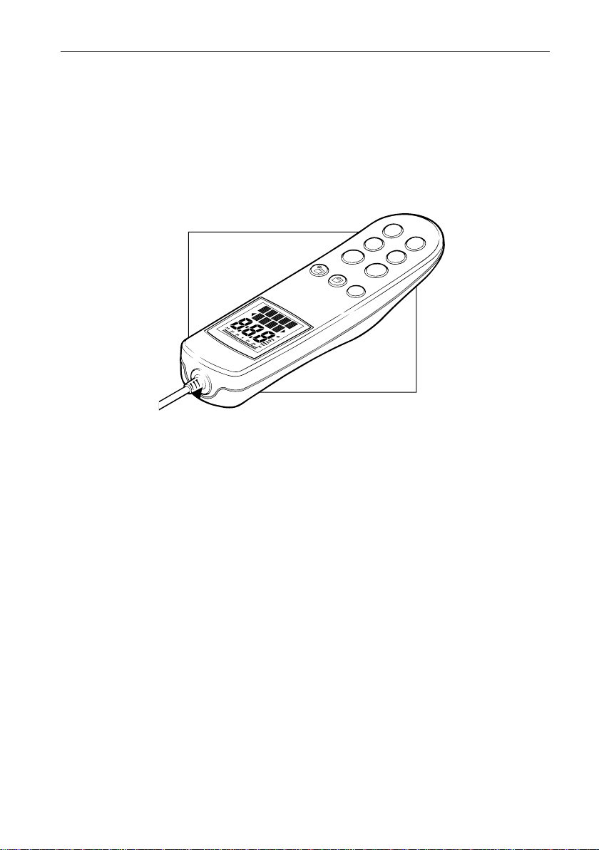
The ST600R is a SeaTalk® compatible autopilot control unit. It is
designed for use as a repeater in an autopilot system, allowing
autopilot control from a secondary location, or as the control unit for
a Type 100/300 Course Computer. It can also repeat instrument
data in an extensive set of Data Pages.
There are five operating modes:
Standby:Autopilot off
Auto:Autopilot engaged and locked onto a heading
Track:Autopilot maintains a track between two waypoints
created using a navigation system
Vane:Autopilot maintains a courserelative to an apparent
wind angle
Manual:Autopilot off during joystick control of steering
When the ST600R is being used to repeat instrument data, “pop-up
pilot” pages are displayed for 5 seconds whenever a change in
autopilot control is made.
The ST600R also provides the following:
•Setup and calibration options to suit each installation, giving
maximum performance with many types of boat and three
calibration menus (user, intermediate and dealer)
•Dockside rudder calibration feature that automatically determines
the characteristics of your installation, and adjusts for them, before
you set sail
•CodeLock security support
• Automatic tack facility that can be in used in Auto and Vane modes
• Automatic compass deviation correction
• Northerly/Southerly heading compensation
• Automatic heading deadband - seastate control
• Waypoint advance feature
1
Page 13

2
ST600R Autopilot Control Unit
1.2 Specification
• Power Supply: 8.5 to 16.5V DC
• Current consumption:
Standby: 60mA (less than 200mA with full lighting)
• Operating temperature: 0°C to +70°C (32°F to 158°F)
• Nine button illuminated digital keypad
• LCD display of heading, locked course and navigational data, with
three levels of illumination
Page 14
Chapter 2: Basic Operation
Chapter 2: Basic Operation
This chapter provides summary diagrams of the screen layout and
key functions. It also provides instructions for engaging the
autopilot and using Auto mode, changing the lighting and
displaying Data Pages.
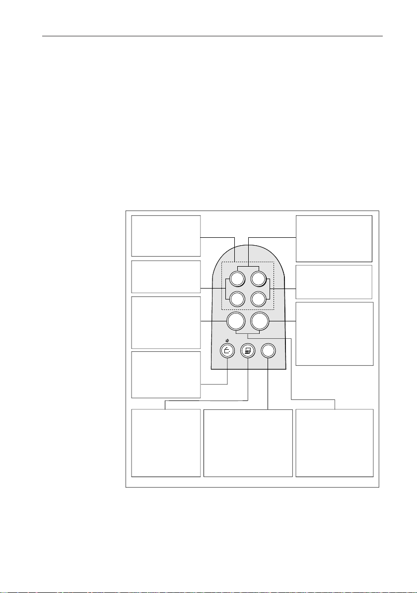
2.1 Key Functions
The autopilot is controlled using simple push-button operations, all
of which are confirmed with a beep. In addition to the main single
key functions, there are several dual key functions.
3
Port and Starboard
Course Change
Keys -1 & -10 (port)
+1 & +10 (starb'd)
-1 plus -10
Press together for
AutoTack to port
STANDBY
Press for Standby
mode
Press and hold for
Setup modes
CHAPTER
Press for
Data Chapter
Press for 1 second
for lamp control
PAGE
Press to cycle
through the
SeaTalk pages.
Press for 1 second
to return to the
previous page.
--1
+1
+10
-
-10
auto
stdby
track
TRACK
Press for Track mode
from Auto
Press to accept waypoint
advance
Press for 1 second to skip
waypoint
-1 plus +1
Press together for
Response level
Press together for 1
second for Rudder Gain
+1 plus +10
Press together for
AutoTack to starboard
AUTO
Press for Auto mode
Press for 1 second
for Last Heading
Press again to
accept Last Heading
STANDBY + AUTO
Press for Vane mode
Press for 1 second
for Last Wind
Press again to accept
Last Wind
• The autopilot always powers up in Standby mode. (If the words
CODE LOCK are displayed, enter your code as described in
Chapter 4.)
• Course changes are made using the -1, +1, -10 and +10 keys.
• Return to manual steering at any time by pressing STANDBY.
D3447-1
Page 15
4 ST600R Autopilot Control Unit
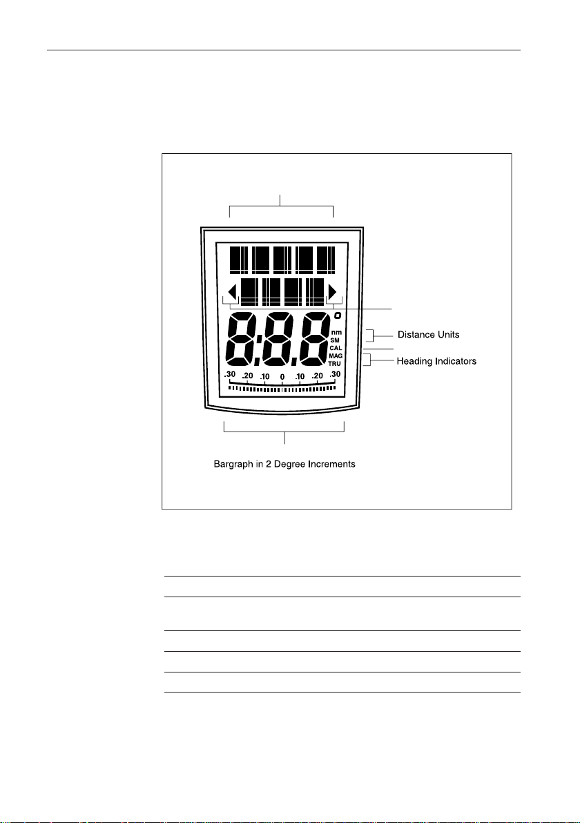
2.2 Display Layout
The following illustration shows all the elements, together with a
brief description, that make up the ST600R autopilot LCD display.
Variable Text Region
(5+4 Characters/Digits Maximum)
Port and Starboard
Direction to Steer
Indicators
Calibration Indicator
Rudder or Steer Direction Indicator
D3682-1
• The bar graph at the bottom of the display is normally the rudder bar.
If it has been set as a direction-to-steer indicator (refer to User
Setup), the display depends on the current mode (see below).
Mode Bar
Standby Not used (rudder angle if feedback transducer is
connected to autopilot)
Auto Heading error bar
Track Cross track error (XTE) bar, in 0.02nm increments
Vane Wind angle error bar
• If neither distance units (nm or SM) is displayed, the distance is in
Km.
Page 16
Chapter 2: Basic Operation
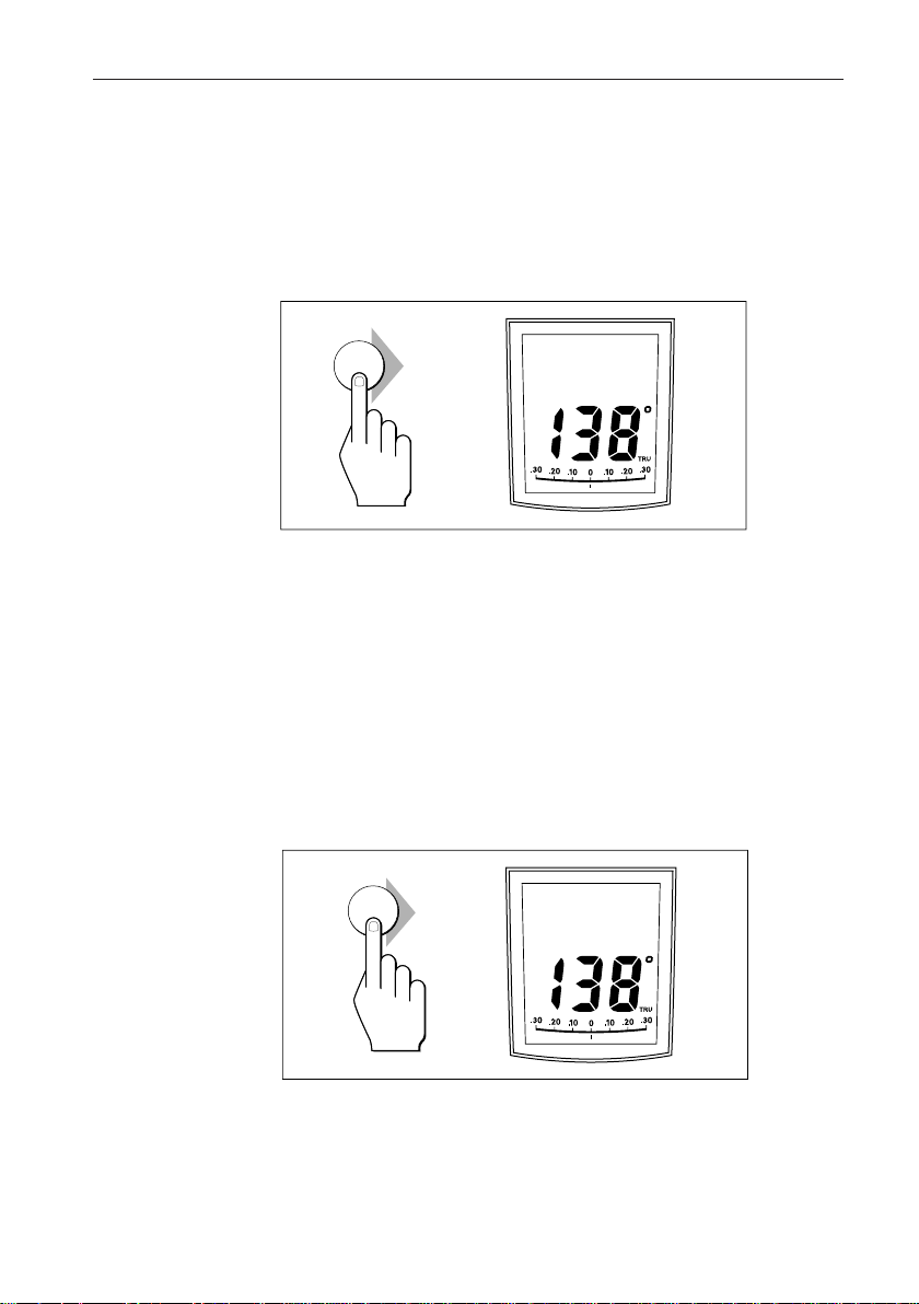
1. Steady the vessel on the required heading.
2. Press AUTO.
5
2.3 Using Auto Mode
Engaging the Autopilot (Auto)
auto
AUTO
DXXXX-1
• In Auto mode, the display shows the locked autopilot heading.
Caution: Passage making under autopilot control is an enjoyable
experience that can, if you are not careful, lead to the relaxation
of the permanent watch. A permanent watch MUST be
maintained no matter how clear the sea may appear to be.
Remember, a large ship can travel two miles in five minutes –
just the time it takes to make a cup of coffee.
Disengaging the Autopilot (Standby) to Return to
Hand Steering
• Press STANDBY.
stdby
STDBY
DXXXX-1
• In Standby mode, the display shows the vessel’s current compass
heading.
• The previous autopilot heading is memorised and can be recalled
(see opposite).
Page 17
6 ST600R Autopilot Control Unit
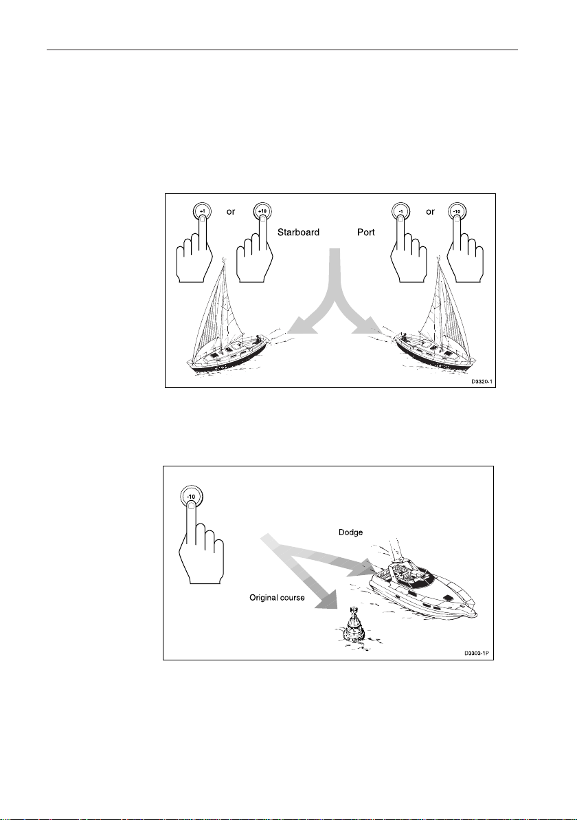
Changing Course in Auto Mode
• The +1 and +10 (starboard) and –1 and –10 (port) keys are used to
change the locked heading, in increments of 1° and 10°, when the
autopilot has control.
Example: a 30° course change to port = press –10 three times.
Dodging Obstacles in Auto Mode
Select a course change in the appropriate direction, for example,
port 30° = -10 three times.
• When safely clear of the obstacle, you can reverse the previous
course change (for example, press +10 three times), or return to the
previous locked heading (LAST HDG).
Page 18
Chapter 2: Basic Operation
1. Press AUTO for 1 second. The previous locked heading (LAST
Note: A direction-to-steer indicator is displayed to show you the direction
2. To accept this heading, and resume the original course, press AUTO
7
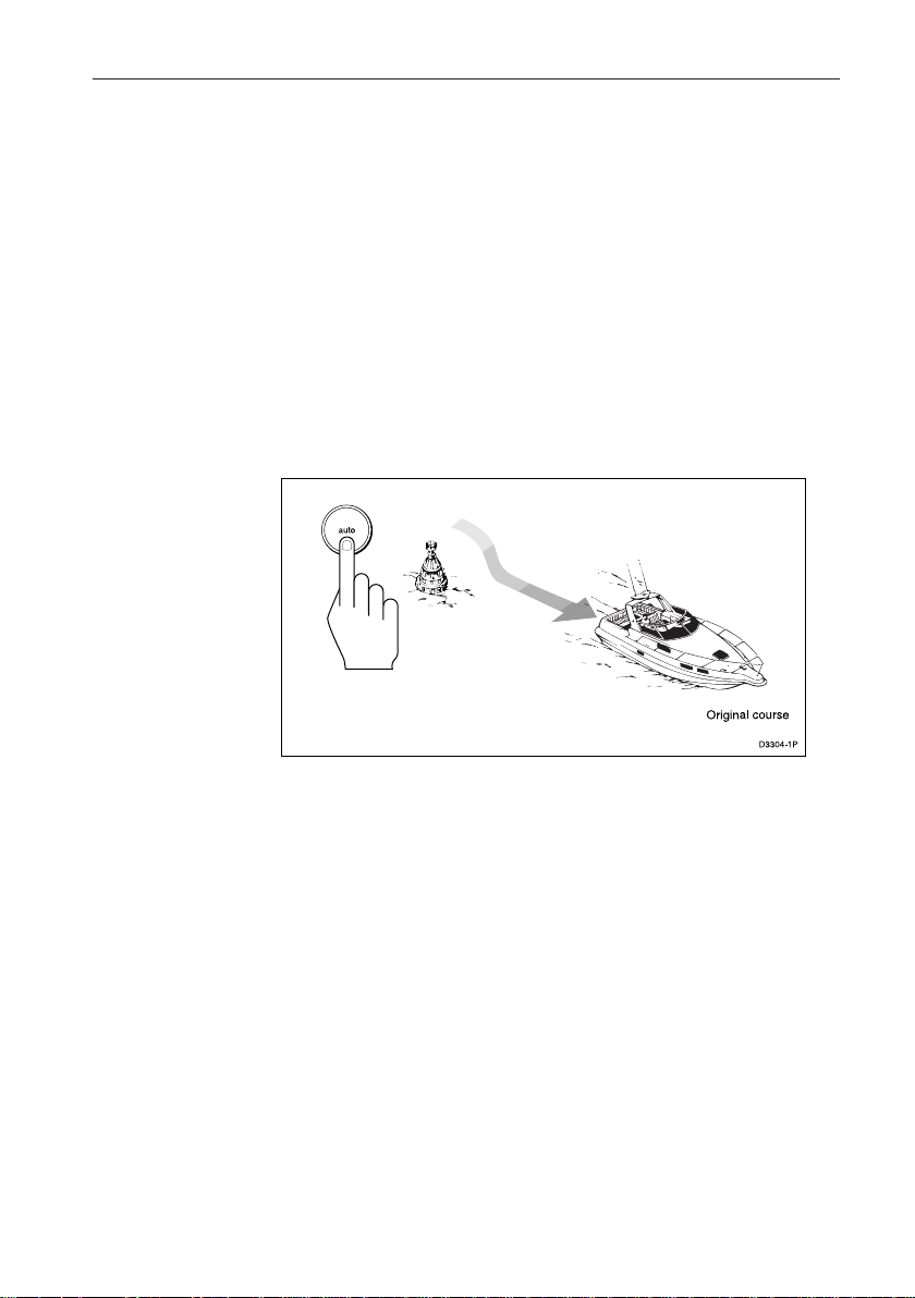
Returning to the Previous Locked Heading
(LAST HDG)
If you steer your vessel away from the selected locked heading (for
example, executing a dodge manoeuvre or selecting Standby) you
can return to the previous locked heading as follows:
HDG) is displayed for 7 seconds and the display flashes.
the vessel will turn.
once within this 7 second period.
If you do not press AUTO while the display is flashing, the current
heading will be maintained.
Page 19
8 ST600R Autopilot Control Unit
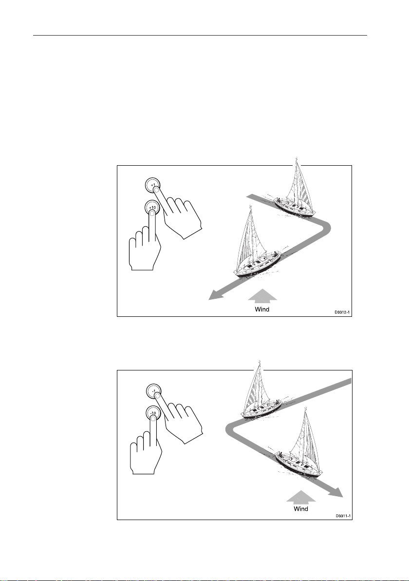
Automatic Tack (AutoTack)
The autopilot has a built in automatic tack facility that turns the
vessel through a predetermined angle (the factory default, set in
Dealer calibration, is 100°) in the required direction.
AutoTack to Starboard
• Press the +1 and +10 keys together to tack to starboard.
AutoTack to Port
• Press the -1 and -10 keys together to tack to port .
Page 20

Chapter 2: Basic Operation
1. To cancel the off course alarm, press STANDBY to return to hand
2. Make sure your vessel is not carrying too much sail or the sails are
9
Off Course Alarm
The off course alarm sounds if the locked autopilot heading and the
vessel’s current heading differ for more than 20 seconds, and by
more than the alarm angle set in calibration (the factory default
is 20°).
steering.
badly balanced. Significant improvements in course keeping can
usually be obtained by improving sail balance.
Operating Hints
Making Major Course Changes
• It is sound seamanship to make major course changes only when
steering manually.
• Manual course changes ensure that obstructions or other vessels are
cleared properly, and due account taken of the changed wind and sea
conditions on the new heading prior to engaging the autopilot.
Course Changes Under Autopilot Control
It is important to understand the effect of sudden trim changes on
steering performance. When a sudden trim change occurs, due, for
example, to weather helm or sail imbalance, there will be a delay
before the automatic trim applies rudder to restore the locked
heading. This correction can take up to one minute.
Large course changes, which change the apparent wind direction,
can produce large trim changes. In these situations, the autopilot will
not immediately assume the new automatic heading, and will only
settle onto course when the automatic trim has been fully
established.
Page 21

10 ST600R Autopilot Control Unit
To eliminate this problem, the following procedure can be adopted
for large course changes:
1. Note the required new heading.
2. Select STANDBY and steer manually.
3. Bring the vessel onto the new heading.
4. Select AUTO and let the vessel settle onto course.
5. Bring the vessel to the final course with 1° increments.
Gusty Conditions
In gusty conditions, the course may tend to wander slightly,
particularly if the sails are badly balanced. Significant
improvements in course keeping can always be obtained by
improving sail balance. Bear in mind the following important
points:
• Do not allow the yacht to heel over excessively
• Ease the mainsheet traveller to leeward to reduce heeling and
weather helm
• If necessary, reef the mainsail a little early
It is also advisable, whenever possible, to avoid sailing with the
wind dead astern in very strong winds and large seas.
Ideally, the wind should be brought at least 30° away from a dead
run and, in severe conditions, it may be advisable to remove the
mainsail altogether and sail under headsail only.
Provided these simple precautions are taken, the autopilot will be
able to maintain competent control in gale force conditions.
2.4 Manual Mode
If your system is fitted with a joystick, the ST600R will enter
Manual mode when the joystick is in use.
The ST600R will return to Standby mode when the joystick button
is released, or if you press the STANDBY key on the ST600R.
Page 22
Chapter 2: Basic Operation
LAMP
DXXXX-1
LAMP
LAMP LAMP
LAMP
STBY
• Press for 1 second, from any mode, to enter illumination
• Subsequent presses of the key cycles the possible illumination
Notes: If other SeaTalk instruments or autopilot control units are connected
11
2.5 Display and Keypad Illumination
adjustment mode and turn the lights on.
settings: L3, L2, L1, OFF, L1, L2, L3 etc. where L3 is the brightest
setting.
The display times out to normal operation after 7 seconds of keypad
inactivity.
Pressing any other key before the 7 second time-out will select the
mode assigned to that key (for example, AUTO selects Auto mode,
STANDBY selects Standby mode).
to SeaTalk, the illumination can be adjusted from these units.
Any adjustments to the illumination are lost when the unit is
switched off.
The keys are still lit at a courtesy level when the display lighting is off.
If the illumination is initially OFF, upon entry to illumination adjustment
mode the illumination is set to level 3.
Page 23
12 ST600R Autopilot Control Unit
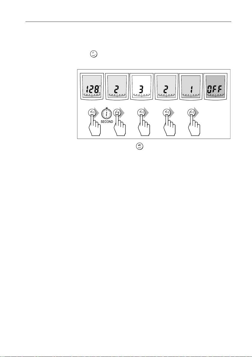
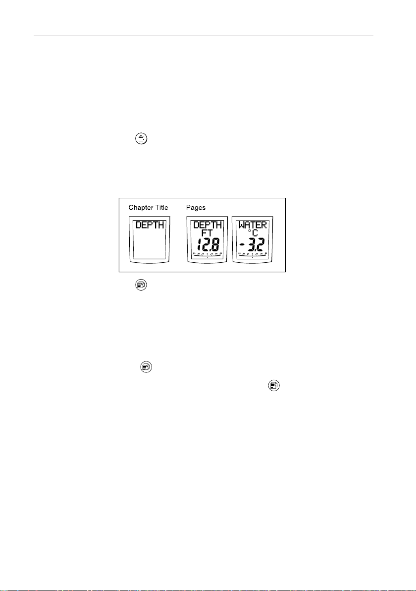
2.6 SeaTalk Data Pages
The ST600R can display 21 “pages” of SeaTalk data, grouped into 6
“chapters” (see opposite page).
Changing Chapters
The key is used to cycle through the chapters. The chapter title
(for example, SPEED) is displayed for 2 seconds, then the first page
in the chapter is displayed.
Cycling Pages
The key is used to cycle through the pages in the current chapter.
Once a Data Page is selected, this page becomes the principle
autopilot display. The autopilot mode displays (Standby, Auto,
Track, Vane and Manual) then become “pop-ups”, and are
displayed for 5 seconds when the autopilot mode is changed or a
course change is made.
• Press to display each Data Page in turn.
• To return to a previous Data Page, press for 1 second. You can
continue to move backwards through the Data Page sequence in this
way.
• If the required data for a page is not available, dashes are displayed
instead of a value.
• Most displays are repeated data and cannot be adjusted. The
exceptions are the Response and Rudder Gain pages, which can be
adjusted using the +1 and -1 keys (refer to section 3.3 for the
alternative method of adjusting the Response/Gain).
• The autopilot bar graph remains in use.
• The “direction-to-steer” arrows relate to the Data Page information.
Page 24
Chapter 2: Basic Operation
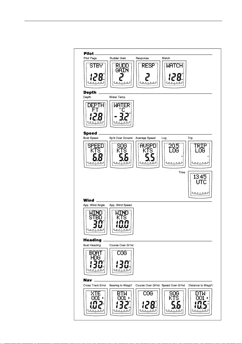
13
SeaTalk Data Chart
Page 25

14 ST600R Autopilot Control Unit
Chapter 3: Advanced Opera tion
This chapter provides information on:
• Operation in Track mode
• Operation in Vane mode (WindTrim)
• Adjusting response and rudder gain
• Alarms
3.1 Operation in Track Mode
Track mode is used to maintain a track between two waypoints
created on a GPS, Decca, or Loran navigation system. The autopilot
will then compute any course changes to keep your boat on track,
automatically compensating for tidal streams and leeway.
The autopilot can receive cross track error (the distance your vessel
is from a planned track) from a SeaTalk navigation instrument or
chartplotter
Track mode is selected by pressing the TRACK key, but can only be
selected in Auto mode. You can return to either Auto or Standby
from Track as follows:
• Press AUTO to leave Track mode and return to Auto mode.
• Press STANDBY to leave Track mode and return to manual
steering.
Initiating Track Mode
When initiating Track mode, the track can be acquired in one of two
ways:
• Automatic acquisition – when cross track error and bearing to
waypoint data are available
• Manual acquisition – when cross track error is the only available
data
Page 26
Chapter 3: Advanced Operation
Automatic Acquisition
Automatic acquisition can only be achieved if the pilot is receiving
cross track error and bearing to waypoint information (via SeaTalk
or NMEA 0183). It is initiated as follows:
1. Bring the vessel to within 0.1nm of track
2. Press AUTO.
3. Press TRACK to enter Track mode, with the current locked heading
displayed.
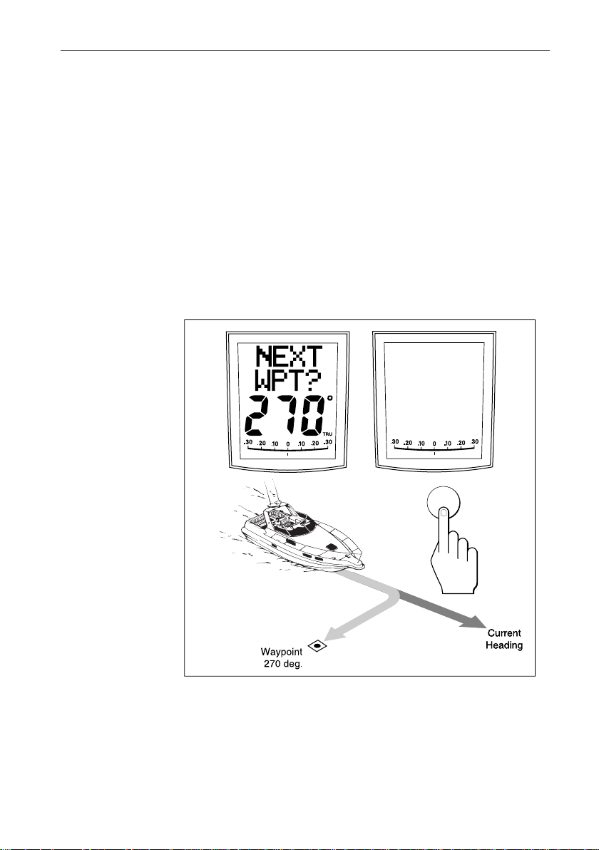
After a short delay for data acquisition, the Waypoint Advance
alarm will sound, and the display will show the planned bearing to
waypoint alternating with the direction in which the boat will turn.
15
STBD
track
Note: If the vessel is further than 0.3nm from the track, the Large Cross
Track Error alarm will sound. Press STANDBY to cancel the alarm,
hand steer closer to the track, and press AUTO and TRACK again.
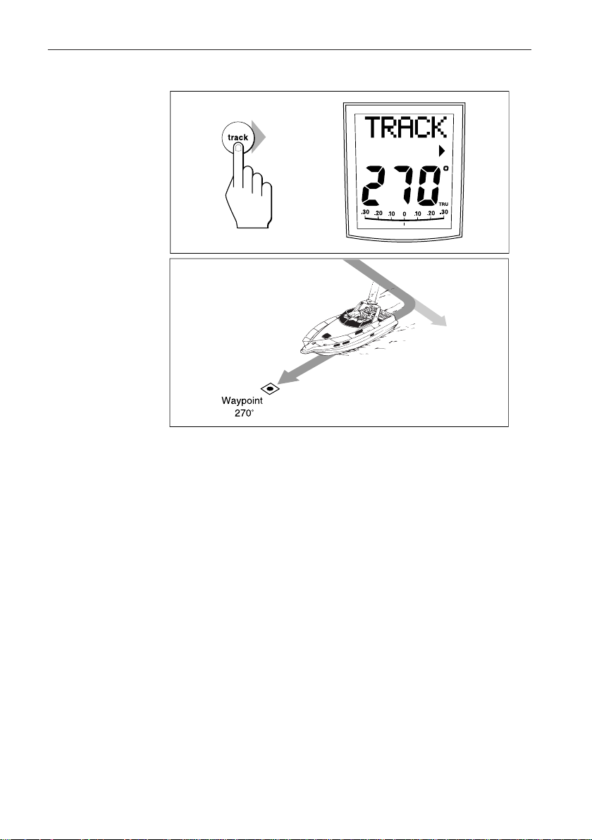
4. Check that it is safe to turn onto the new course.
5. Press the TRACK key. The boat will turn on to the new course and
the alarm will be cancelled.
Page 27
16 ST600R Autopilot Control Unit
Previous
Heading
D3505-1
• The display shows the new bearing to waypoint.
Manual Acquisition
For manual track acquisition when cross track error is the only data
available:
1. Steer the vessel to within 0.1nm of track.
2. Bring the heading to within 5° of the bearing to the next waypoint.
3. Press AUTO.
4. Press TRACK to enter Track mode.
• The display shows the cross track error and the locked pilot heading.
Note: At low speeds, the effect of tidal streams is far more significant than it
is at higher speeds. Providing the tidal flow is less than 35% of the
vessel’s speed, no noticeable difference should occur in the
performance of Track mode. However, extra care should be taken
during manual acquisition, as follows:
• Ensure that the vessel is as close as possible to track, and the
direction made good over the ground is as close as possible to the
direction of the next waypoint, before selecting Track mode.
• Make positive positional checks at regular intervals, especially if
navigational hazards are close by.
Page 28
Chapter 3: Advanced Operation
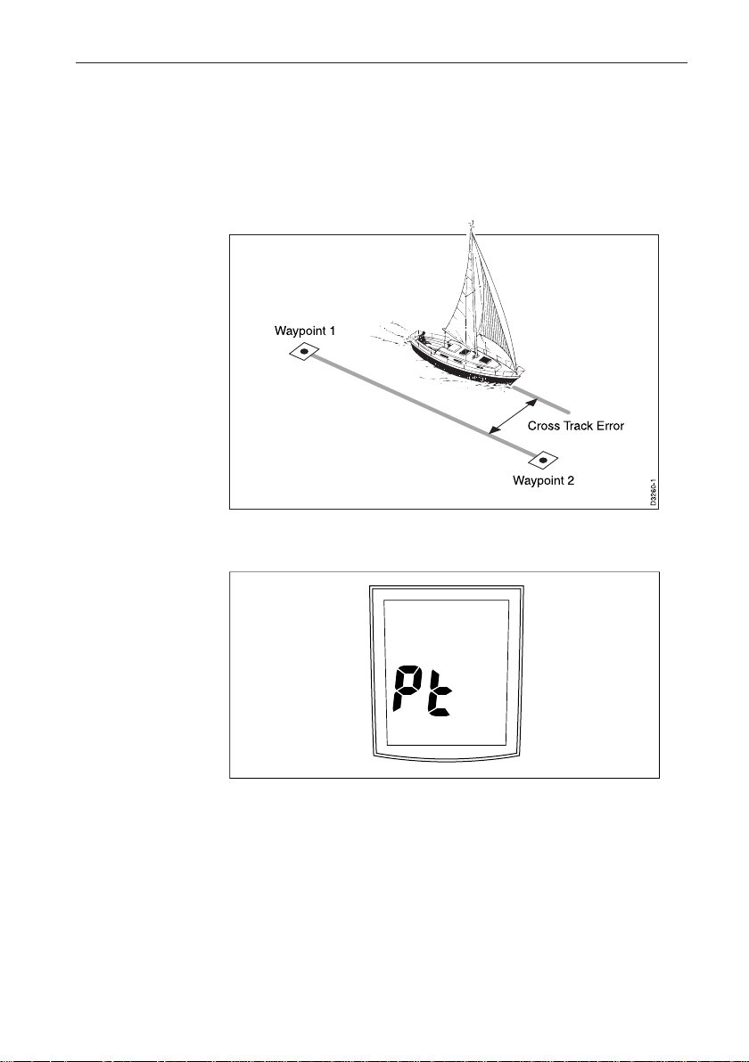
Cross Track Error
Cross track error (XTE) is the distance between the current position
and a planned route. This is displayed in nautical miles (nm), statute
miles (SM) or kilometres, and is taken directly from your navigator.
The Large Cross Track Error alarm sounds if the cross track exceeds
0.3nm.
17
LARGE
XTE
DXXXX-1
• The direction of the error is identified as “Pt” port or “Stb”
starboard.
• To cancel the alarm, press STANDBY to return to hand steering, or
AUTO to return to Auto mode.
Note: If the Large Cross Track Error alarm sounds, it is usually an indication
that the cross tide is too great for the vessel’s current speed.
Page 29

18 ST600R Autopilot Control Unit
Tidal Stream Compensation
Under most conditions, Track mode will hold the selected track to
within ±0.05nm (300ft) or better.
The autopilot takes account of vessel speed when computing course
changes to ensure optimum performance over a wide range of vessel
speeds. If speed data is available, the autopilot uses the measured
vessel speed. Otherwise, the Speed Over Ground (SOG) or specified
cruise speed is used, depending on the calibration setting (see
“Dealer Setup” in Chapter 5).
Vessel's speed
Vessel's
Waypoint Arrival and Advance
If your navigation receiver transmits valid NMEA waypoint number
and bearing to waypoint data, it is possible to advance from one
waypoint to the next by simply pressing TRACK.
Arrival
As the vessel passes the target waypoint, the navigation receiver
should select (manually or automatically) the next target waypoint.
The autopilot detects the new target waypoint number, sounds the
Waypoint Advance alarm and displays the Waypoint Advance
information. This display shows the new bearing to waypoint and
the direction the boat will turn to acquire the new track.
To accept the new target waypoint, press TRACK.
Page 30

Chapter 3: Advanced Operation
Skipping a Waypoint – SeaTalk Navigators Only
If you wish to advance to the next waypoint before you have arrived
at the target waypoint, press TRACK for 1 second. The Waypoint
Advance information for the next waypoint is displayed.
Advance
While the waypoint advance alarm is sounding, Track mode is
suspended and the autopilot maintains the current boat heading.
1. Check that it is safe to turn onto the new track.
2. Press the TRACK key. This will cancel the waypoint arrival alarm
and turn the boat towards the next waypoint.
Unless the Waypoint Advance is accepted in the above manner, the
alarm will continue to sound and the current heading will be
maintained.
Dodges
Full control is still available from the keypad when the autopilot is in
Track mode.
Initiating a Dodge Manoeuvre
In track mode, dodge manoeuvres are accomplished by simply
selecting the desired course change using the course change keys
(-1, +1, -10 or +10).
19
Cancelling a Dodge Manoeuvre
Once the hazard has been avoided, the course change selected for
the dodge manoeuvre should be cancelled by selecting an equal
course change in the opposite direction.
Note: Provided the vessel remains within 0.1nm of track, there is no need to
steer back towards the track.
Safety
Passage making in Track mode removes the chores of compensating
for wind and tidal drift, and will aid precise navigation. However, it
is important to maintain an accurate log with regular plots.
Position Confirmation at the Start of a Passage
At the start of a passage you must always confirm the fix given by
the position transducer, using an easily identifiable fixed object.
Check for fixed positional errors and compensate for them.
Page 31

20ST600R Autopilot Control Unit
Verifying Computed Positions
•Verify the computed position with a dead reckoned position,
calculated from the average course steered and the distance logged.
Plot Frequency
•In open water, plots should be at least hourly.
•In confined waters, or when potential hazards are near, plots should
be more frequent.
•Local variations in radio signal quality, and changes in the tidal
stream, will produce deviations from the desired track.
Setting Waypoints
•When setting waypoints, remember that deviations will occur.
•Thoroughly check along each track.
•Check up to 0.5nm each side of the track to ensure that there are no
hazards within the zone.
General
The use of track mode will enable accurate track keeping even in
complex navigational situations. However, it cannot remove the
responsibility of the skipper to ensure the safety of his vessel at all
times by careful navigation and frequent position checks.
3.2 Operation in Vane Mode (WindTrim)
Vane mode, also known as WindTrim, allows the autopilot to
maintain a course relative to an apparent wind angle. It uses wind
trim to eliminate the effects of turbulence and short term wind
variations, and provides smooth precise performance under Vane
mode operation with minimal power consumption.
Vane mode uses the fluxgate compass as the primary heading
reference and, as changes in the apparent wind angle occur, the
locked compass heading is adjusted to maintain the original
apparent wind angle.
To use Vane mode, the autopilot must receive wind information
from one of the following sources:
•
SeaTalk Wind instrument, connected to the autopilot via SeaTalk
•NMEA wind information
•Raymarine wind vane connected to a SeaTalk interface box
Page 32

Chapter 3: Advanced Operation
DXXXX-1
WIND
145P
autostdby
Selecting Vane Mode
Vane mode can be selected from either Standby or Auto modes, as
follows:
1. Steady the vessel onto a heading at which the apparent wind angle is
close to angle you require.
2. Press STANDBY and AUTO together to select Vane mode and
lock the current apparent wind angle.
• The locked heading is displayed in large characters. The locked
apparent wind angle is displayed above the heading, with an P (port)
or S (starboard) direction indicator.
• The boat heading is adjusted by the autopilot to maintain the locked
apparent wind angle.
21
Adjusting the Locked Wind Angle
The locked wind angle can be adjusted by changing course using the
-1, +1, -10 and +10 keys.
For example, to bear away by 10° when the vessel is on starboard
tack, press -10 to turn the vessel 10° to port. The locked apparent
wind angle and locked heading both change by 10°. The new
apparent wind angle is maintained, and the locked heading adjusted
by the autopilot as required.
Note: This method does not apply to systems using the Type 100/300
Course Computer. Also, this method should only be used for minor
adjustments to the apparent wind angle, since turning the boat
affects the relationship between the true and apparent wind angles.
For major changes, return to Standby mode, steer onto the new
heading, and reselect Vane mode.
Page 33

22 ST600R Autopilot Control Unit
DXXXX-1
LAST
autostdby
Returning to the Previous Apparent Wind Angle
(LAST WND)
If for any reason the vessel is steered away from the selected
apparent wind angle (for example, a dodge manoeuvre or selecting
Standby) you can return to the previous locked wind angle:
1. Press STANDBY and AUTO together for 1 second to display the
previous apparent wind angle (LAST WND).
The LAST WND? text alternates with the previous wind angle and
direction. The previous locked heading is displayed, with an
indicator to show you the direction in which the vessel will turn.
2. Check that it is safe to turn on to this course.
3. To accept this apparent wind angle, press STANDBY and AUTO
together within 7 seconds.
If you do not accept the previous wind within this time, the autopilot
will lock on to the current apparent wind angle.
Dodges
Full control is still available from the keypad when the autopilot is in
Vane mode.
• Dodge manoeuvres are accomplished by simply selecting the
desired course change using the course change keys
(-1, +1, -10 or +10). Both the locked heading and locked apparent
wind angle are adjusted.
• Once the hazard has been avoided, you can reverse the previous
course change, or return to the previous apparent wind angle
(LAST WND).
Page 34

Chapter 3: Advanced Operation
Wind Shift Alarm
The wind shift alarm sounds, and the text “WINDSHIFT” is
displayed, if a wind shift of more than 15° is detected.
1. Press STANDBY to cancel the alarm and return to hand steering,
and steer onto the required heading.
2. Press STANDBY and AUTO together to return to Vane mode with
the new apparent wind angle.
Using AutoTack in Vane Mode
The automatic tack function, when used in Vane mode, turns the
vessel so that the locked apparent wind angle is changed to an equal
angle on the opposite bow.
Initially, the autopilot turns the vessel through the specified tack
angle (the factory default is 100°). Then the locked heading is
adjusted until the required apparent wind angle is achieved.
• To tack to starboard, press the +1 and +10 keys together.
• To tack to port, press the -1 and -10 keys together.
Note: If you use the Autotack function in Vane mode, it is important to check
that the wind vane has been centred accurately when it was installed.
Also, the AutoTack feature cannot be adjusted if you are using a
Type 100/300 Course Computer.
23
Page 35

24 ST600R Autopilot Control Unit
AutoTack
Angle
Automatic Course
Ajustment (If Required)
to Mirror the Previous
Apparent Wind Angle
Apparent Wind Angle
D3391-1
Operating Hints
• Major changes to the selected apparent wind angle should be made
by returning to Standby mode, changing course manually, then
reselecting Vane Mode.
• Vane mode filters the windvane output. This provides the optimum
response for off-shore conditions where genuine shifts in wind
direction occur gradually.
• In gusty and unsteady inshore conditions, it is best to sail a few
degrees further off the wind so that changes in apparent wind
direction can be tolerated.
• It is important to ensure that the amount of standing helm is
minimised by careful sail trimming and positioning of the mainsheet
traveller.
• The headsail and mainsail should be reefed a little early rather than
too late.
Page 36

Chapter 3: Advanced Operation
3.3 Adjusting Autopilot Performance
The response level and rudder gain can be adjusted during normal
operation using a combined key-press.
The default calibration settings for response and rudder gain (refer to
Dealer Setup) are restored when the system is powered on.
Changing the Response Level (Auto Seastate)
The response level controls the relationship between the autopilot’s
course keeping accuracy and the amount of helm/drive activity.
• Response Level 1, Auto Seastate (Automatic Deadband), causes the
autopilot to gradually ignore repetitive movements of the vessel and
only react to true variations in course. This provides the best
compromise between power consumption and course keeping
accuracy, and is the default calibration setting.
• Response Level 2 (Minimum Deadband) provides the tightest
course keeping possible. However, tighter course keeping results in
increased power consumption and drive unit activity.
• Response Level 3 (also Minimum Deadband) provides the tightest
course keeping possible by introducing yaw damping (requires a
rate gyro and is only available with course computer systems).
The response can be changed at any time. To do so:
1. Press the +1 and -1 keys together momentarily to display the
Response screen.
2. Press +1 or -1 to change the response level.
25
3. Wait for 5 seconds, or press , to return to the previous display.
Normal Operation
BOAT
HDG
RESP
RESP
DXXXX-1
Page 37

26 ST600R Autopilot Control Unit
Changing the Rudder Gain
Press the +1 and -1 keys together for 1 second to display the Rudder
Gain screen, and adjust the setting in the same way as for the
response level. Refer to Chapter 7, “Post Installation Procedures”,
for instructions on how to check that the rudder gain is set correctly.
Warning: It is important that the rudder gain is correctly set on planing
craft. Incorrect adjustment will lead to poor steering
performance and is dangerous at high speeds.
3.4 Alarms
This section summarises the alarms (in order of priority) that are
reported by the ST600R.
Press STANDBY to clear an alarm and return to hand steering,
unless indicated otherwise.
ST
FAIL
WIND
SHFT
NEXT LOW
NO
LINK
LARGE
XTE
BATT
AUTO
RELSE
DRIVE
STOP
WATCH WATCH
OFF
CRS
NO
DATA
Page 38

Chapter 3: Advanced Operation
SeaTalk Failure
This silent alarm indicates that there is a wiring fault in the SeaTalk
connection.
No Link
This silent alarm indicates that there is no link between the ST600R
and the course computer.
Auto Release
The Auto Release alarm is activated when an Raymarine stern drive
actuator is returned to manual steering.
Off Course
This alarm is activated when the vessel has been off course from the
locked heading by more than the specified angle for more than 20
seconds (see Section 2.3, “Using Auto Mode”).
The alarm is cleared if the heading recovers or the course is
changed, or if the operating mode is changed.
Wind Shift
This alarm is activated when the apparent wind angle requires an
adjustment of the locked heading by more than 15° (see Section 3.2,
“Operation in Vane Mode”).
27
Large Cross Track Error
This alarm is activated when the cross track error exceeds 0.3nm
(see Section 3.1, “Operation in Track Mode”).
The autopilot stops controlling the locked heading as soon as this
condition occurs.
The alarm is cleared if the heading recovers or the course is
changed, or if the operating mode is changed.
Page 39

28 ST600R Autopilot Control Unit
Drive Stopped
This alarm is activated if the autopilot is unable to turn the rudder.
This occurs if the weather load on helm is too high, or if the
requested rudder position is past the preset rudder limits or the
rudder end-stops.
Data Not Received
This alarm is displayed in the following circumstances:
• Track mode is engaged and the autopilot is not receiving SeaTalk
navigation data.
• Track mode is engaged and the position transducer (GPS, Loran,
Decca) is receiving a low strength signal – this will clear as soon as
the signal strength improves.
• Vane mode is engaged and the autopilot has not received wind angle
data for 30 seconds.
The autopilot stops adjusting the locked heading as soon as data is
lost.
Waypoint Advance
The waypoint advance alarm sounds whenever the target waypoint
number changes, which occurs in the following circumstances:
• Automatic acquisition is selected by pressing TRACK from Auto
mode
• Waypoint advance is requested by pressing TRACK for 1 second in
Track mode (SeaTalk Navigators only).
When the alarm sounds, the pilot continues on its current heading,
but displays the bearing to the next waypoint and the direction in
which the boat will turn to take up that bearing.
Check that it is safe to turn onto the new track, and press TRACK to
accept the waypoint advance.
To cancel the alarm without accepting the waypoint advance, press
STANDBY to return to hand steering, or AUTO to return to Auto.
Note: The waypoint advance will only operate on pilots receiving valid
bearing to waypoint and waypoint number information.
Page 40

Chapter 3: Advanced Operation
Low Battery
The Low Battery alarm sounds when the supply voltage drops
below 10V (±0.5V).
Press STANDBY to clear the alarm and return to hand steering.
Start the engine to recharge the battery.
Watch Alarm
The Watch alarm is activated in Watch mode when the timer Page is
displayed.
• The watch timer starts counting.
• When the timer reaches 3 minutes, the text on the display starts
flashing to indicate the last minute of Watch alarm.
• When the timer reaches 4 minutes, the audible Watch alarm is
activated.
3. Press AUTO at any time to silence the alarm and reset the timer to
4 minutes (Pressing any other key resets the timer and performs the
key’s normal function).
4. To clear Watch mode, press to display the PILOT page.
Note: Watch mode is also cleared if the chapter is changed or a pilot mode
change occurs.
29
Man Overboard (MOB)
If a man overboard (MOB) message is received from another
instrument on the SeaTalk system, the text “MOB” is shown instead
of the waypoint number for the XTE, DTW and BTW Data Pages.
If the autopilot is operating in Track mode, the Waypoint Advance
alarm will sound to notify the change in waypoint.
Page 41

30 ST600R Autopilot Control Unit
Page 42

Chapter 4: CodeLock
Chapter 4: CodeLock
CodeLock is a personal four-digit security feature designed to
protect your valuable instruments against theft. You don’t have to
activate the system, but it’s there if you need to. You can activate it
using any CodeLock-compatible control unit on your SeaTalk
system.
When you first enter a code and activate CodeLock, the code is sent
to all the CodeLock-compatible units on the system. After this,
whenever you power on the system, the units will only start up if
they receive the correct code.
Remember to fix a CodeLock sticker by each instrument, to deter
potential thieves.
4.1 CodeLock Modes
When you set up CodeLock, you can choose whether the code will
be sent automatically or must be entered manually at power on, as
follows:
• Auto mode is used when there is a display unit situated in a secure
location, ideally below deck, or one which can be unplugged and
removed to a secure location. You enter your chosen code on this
“master” unit when you first activate CodeLock. This code is then
automatically sent to all CodeLock-compatible display heads on
SeaTalk, without further intervention, every time the system is
powered on.
• Manual mode is used to provide a higher degree of security,
perhaps when all your instruments are mounted in exposed
locations. In this case, you must enter your personal code every time
the system is switched on. The code can be entered into any
convenient CodeLock-compatible control unit, and is then sent to all
the other compatible units via SeaTalk.
31
4.2 Setting Up CodeLock
CodeLock is set on the ST600R using the Intermediate Setup
options.
Page 43

32 ST600R Autopilot Control Unit
Initial Setup
When you first install your ST600R, CodeLock is set OFF. To
activate CodeLock, refer to the following flow diagram.
Setting CodeLock
Normal Operation
Software Version CodeLock Screen
Software Version
STBY
VERS
ION
stdby
Enter a Four Digit Code Number
Enter a number at the flashing cursor:
+1
--1
+10
--10
auto
stdby
Code Complete Auto Mode or...
CODE
0345
Code Set Normal Operation
CODE
SET
-1 cycles: 0 9 8 7 6 5 4 3 2 1
+1 cycles: 0 1 2 3 4 5 6 7 8 9
Move the cursor to the next position
track
CODE
AUTO
STBY
stdby
+1
OR
--1
4
Manual Mode
CODE
MAN
9 10
• Make sure that the autopilot is in Standby mode before accessing
Intermediate Setup.
• If the CAL LOCK screen is displayed instead of the VERSION
screen, you need to turn off the lock feature in Dealer Setup.
The Intermediate Setup displays have the following functions:
Page 44

Chapter 4: CodeLock
Note: If you set up CodeLock in Auto mode, the unit on which you enter the
33
• Manual/Auto modes are explained in section 4.1
• Version numbers: Displays the current ST600R version number,
alternating with the ST60 pilot version number (if applicable). You
cannot adjust these displays.
• CodeLock status: Reports the current status, which can be OFF or
SET. You cannot adjust this display directly.
• CodeLock entry: Used to enter a new code if CodeLock is OFF, or
to turn CodeLock off if it is already set.
• CodeLock mode: Used to select Auto or Manual CodeLock mode,
when a new code has been entered.
Changing the Code or Master Unit
You can change the code from any CodeLock compatible control
unit on your SeaTalk system, provided you know the current code.
new code becomes the new master unit.
To change the code:
1. Display the CodeLock entry screen and enter your current code, as
shown in the flowchart.
The code is checked. If it is incorrect, the four dashes are redisplayed
and you must enter the code again. If it is correct, the CodeLock
status screen is displayed, with the status set to OFF.
2. Press to display the CodeLock entry screen again.
3. Enter the new code (as described in Initial Setup) and move on to the
CodeLock mode selection screen.
4. Set the mode to Auto or Manual, as required.
5. Press and hold STANDBY for 2 seconds to exit Intermediate Setup
and save the new settings.
4.3 Entering Your Code (Manual Mode Only)
If CodeLock has been set up in Manual mode, the correct code must
be entered on one of the control units every time the system is
switched on. The code number created on the master is entered via
the keypad from any CodeLock-compatible instrument, and this
code is then sent to all compatible instruments on the same SeaTalk
bus. Once this code has been received the instruments operate in the
normal way.
Page 45

34 ST600R Autopilot Control Unit
To enter your chosen code number on the ST600R control unit, use
the keys as shown.
CodeLock Manual
Decrease the number at the flashing cursor:
--1
+1
+10
--10
stdby
auto
track
0 9 8 7 6 5 4 3 2 1
Increase the number at the flashing cursor:
0 1 2 3 4 5 6 7 8 9
Move the cursor to the next position
CODE
Press this key to accept code, after the
last number has been entered, and go
to normal operation
Code Complete Normal Operation
CODE
STBY
0345
To enter the code on any other master display unit, refer to the
handbook for that unit for details of the code entry procedure.
4.4 Code Number Problems
• If an incorrect code number has been entered, the four dashes are
redisplayed, with the prompt “code”. Repeat the procedures
illustrated above entering the correct four digit number.
• If you forget your code number, you must take your master unit to an
authorised dealer, together with appropriate proof of ownership such
as the original invoice. The dealer will be able to reset the unit so
that you can enter a new code.
Page 46

Chapter 5: Customising the System
Chapter 5: Customising the System
The ST600R provides setup and configuration options that are used
to adjust the settings for the ST600R itself, the compass, and the
autopilot.
Note: You should perform the post installation procedures described in
Chapter 7 before adjusting any other calibration features.
There are three setup levels:
• User Setup, which controls compass setup, rudder calibration and the
ST600R display features
• Intermediate Setup, which controls the CodeLock security feature
and displays status and version number information (see Chapter 4)
• Dealer Setup, which controls the autopilot settings, and also the
calibration lock which can be used to prevent accidental access to
User and Intermediate Setup
The Dealer Setup options described in this chapter only apply if you
have installed the ST600R as the control unit for a Type 100/300
course computer. If you have installed the ST600R as a repeater unit
on an autopilot system, please refer to the Dealer Setup instructions
in the handbook for the main control unit.
35
5.1 User Setup
The flow chart on the following page shows the User Setup control
procedure, and the setup screens with their default settings.
Information on the functions of the different settings is given in the
remainder of this section.
The following points should be considered:
• Make sure that the autopilot is in Standby mode before you access
User Setup
• If the CAL LOCK screen is displayed instead of the initial page, you
need to turn off the lock feature in Dealer Setup
• Setup options are always saved on exit
Page 47

36
ST600R Autopilot Control Unit
stdby
stdby
* Not applicable to pre version 11 Type 100/300 Course Computer software
Page 48

Chapter 5: Customising the System
Compass Deviation Correction (SWING COMPASS)
The compass deviation correction option allows you to correct the
compass for deviating magnetic fields. The procedure must be
performed as the first item in your initial sea trial, and is described in
detail in Chapter 7, “Post Installation Procedures”.
Deviation Display (DEVIATION)
This screen shows the current deviation value, calculated from the
correction procedure (Swing Compass). You cannot edit this value.
Heading Alignment (ALIGN HDG)
The heading alignment screen shows the current reported heading.
Note: You should always check the compass alignment after performing a
compass deviation correction (see “Post Installation Procedures”).
However, once the initial correction procedure has been performed,
you can make adjustments to the alignment as often as you wish,
without re-correcting your compass.
• Steer onto a known heading, and check the heading displayed.
• If required, adjust the heading value to match the known value, using
the +1, -1, +10 and -10 keys.
37
Pilot Type*
Displays the Pilot Type: sterndrive, displacement, semidisplacement or planing.
Heading Mode (HDG)
Select either magnetic or true heading mode, using the +1 or -1 key.
When heading data is displayed in normal operation, the screen
indicates whether true or magnetic mode has been selected.
* Not applicable to pre version 11 Type 100/300 Course Computer software
Page 49

38
ST600R Autopilot Control Unit
Bar Selection (RUDD BAR)
Select the type of bar graph, using the +1 or -1 key, to be shown at the
bottom of the SeaTalk displays.
The options are as follows:
RUDD BAR: This shows the rudder position, and is the default
setting. Note that a rudder reference transducer is required for
accurate rudder position information.
STEER BAR: The bar graph is used as follows:
Mode Bar
Standby Not used (shows rudder angle if a feedback transducer
connected to the autopilot
Auto Heading error bar
Track XTE bar
Vane Wind angle error bar
Rudder Calibration (DOCKSIDE RUDD CAL)*
Dockside Rudder Calibration is used to automatically calibrate the
rudder range (for systems with a rudder reference unit) and optimise
autopilot performance by matching the autopilot to its installation.
Warning: This procedure moves the helm, and should only be used when
the vessel is at the dockside. For sterndrive systems, the
engines must be running before you start the procedure.
• The auto dockside procedure is not available if the ST600R is used
with a Type 100/300 Course Computer.
• The Dock Side calibration feature is started using the +1 or -1 key.
• If you start the procedure by mistake, press any key to cancel it.
• If the autopilot does not respond, the display shows “AUTO N/A”.
• Activation and completion of Auto Dockside are displayed as:
“AUTO WAIT” and “AUTO END” respectively.
• The “ALIGN RUD” screen follows “AUTO END” if you have a
rudder feedback transducer. The helm should be centred by hand and
the rudder bar adjusted to zero using the -1 and +1 keys.
Quitting User Setup
To quit User Setup at any time, press STANDBY for 2 seconds.
* Not applicable to pre version 11 Type 100/300 Course Computer software
Page 50

Chapter 5: Customising the System
5.2 Dealer Setup: Type 100/300 Course
Computer
This section describes the Dealer Setup options if you have installed
the ST600R as the control unit for a Type 100/300 Course Computer.
If you have installed the ST600R as a repeater unit on another
autopilot system, please refer to the Dealer Setup instructions in the
handbook for the main control unit.
Dealer Setup allows you to customise the autopilot to suit your boat.
However, once you have set the Pilot Type, the factory default
settings will provide safe performance for the initial sea trial, and fine
tuning is not normally required.
The flow chart on below shows you how to enter Dealer Setup, scroll
through the setup displays, adjust the values and exit.
39
Page 51

40
ST600R Autopilot Control Unit
ST600R Dealer ST600R Calibration Screens when
used with the ST6000 Plus and Type 100/300 Course
Computer
Dealer Calibration
stdby
1234
5678
9101112
13 14 15 16
--1
+1
17 18 19 20
--1
Adjusting
Dealer
Calibration
Features
* Not available on pre version 11 Type 100/300 Course Computers
+1
Quitting
Dealer
Calibration
stdby
Page 52

Chapter 5: Customising the System
ST600R Dealer Calibration Screens when used with
the ST4000 Plus and ST5000 Plus Autopilots
The ST600R screen cycle for the ST4000 Plus and ST5000 Plus is as
follows:
• Pilot Type (eg, 4000 WHL)
• Calibration Lock (CAL LOCK)
• Rudder Gain (RUDD GAIN)
• Response (RESP)
• Turn Rate (TURN RATE)
• Rudder Offset (ALIGN RUDD)
• Off Course (OFF CRS)
• Auto Tack (AUTO TACK)
• Cruise Speed (SPEED CRS)
• Rudder Damping (RUDD DAMP)
• Latitude (LAT ADAP)
• Variation (VAR EAST/WEST)
• Drive Type (DRIVE TYPE)
• Automatic Trim (AUTO TRIM)
41
Recommended Settings
The following pages list the default calibration settings for sailing/
power displacement and planing power vessels. Once you have set
the Pilot Type, these will provide good performance for initial sea
trials and can be fine tuned later to optimise performance.
After initial calibration has been carried out, further adjustment can
be made at any time.
The features that can be adjusted are listed in the table at the end of
this chapter, where you can record your settings for future reference.
Information on the functions of the different settings is given in the
remainder of this section.
The following points should be noted:
• Make sure that the autopilot is in Standby mode before you access
Dealer Setup
• Setup options are always saved on exit
Page 53

42
ST600R Autopilot Control Unit
Pilot Type (ST6000 Plus & Type 100/300)
This should be set when the system is first switched on. The default
settings for other Dealer Setup options depend on the pilot type you
select here.
Setting Description
DISPL MNT Displacement
SEMI DIS Semi-displacement
PLANING Planing
SOLENOID Constant running solenoid system
STERN DRV Sterndrive
Default: PLANING
Pilot Type (ST4000 Plus and ST5000 Plus)
When the ST600R is used with the ST4000 Plus and ST5000 Plus
autopilots, the following ‘pilot types’ may be selected.
Setting Description
4000 WHL ST4000 Plus Wheeldrive
4000 TILL ST4000 Plus Tiller Pilot
5000 SAIL ST5000 Plus SailPilot
5000 STRN ST5000 Plus Sterndrive
5000 HYD ST5000 Plus Hydraulic
Calibration Lock
Calibration lock controls whether User Setup and Intermediate Setup
are available, and is intended for charter boat users.
Setting Description
ON Setup ON
OFF Setup OFF
Default: OFF
Page 54

Chapter 5: Customising the System
Rudder Gain
This must be set while under way, as described in Chapter 7, “Post
Installation Procedures”.
Range: 1 to 9
Default: 5 (Displacement)
Rate Level
Rate Level monitors the speed at which rudder is applied when
changing course. Rate level will, if the rate at which the vessel is
turning is too fast, counter this turn with opposite rudder.
The settings available are as follows:
Range: 1 to 9
Defaults: 7 Displacement
43
5 (Semi-displacement)
4 (Planing)
3 (Sterndrive)
7 Semi-displacement
7 Planing
5 Sterndrive
Rudder Offset
You only need to set this option if your system includes a rudder
reference unit.
• Manually place the helm in a central position. The reported rudder
angle is indicated on the rudder bar graphic at the bottom of the
screen.
• Adjust the offset value, using the +1 and -1 keys, until the rudder
position is shown as central on the rudder bar. The offset must be
within the range -7° to +7°.
Range: –7° to +7°
Default: 0
Page 55

44
ST600R Autopilot Control Unit
Rudder Limit
Rudder Limit restricts autopilot rudder movement to just less than
the steering systems mechanical stops. This avoids putting the
steering system under unnecessary load.
The range available is as follows:
Range: 15° to 40°
Defaults: 30° Displacement, semi-displacement, planing
20° Sterndrive
Turn Limit
This limits the rate of turn of your vessel when under autopilot
control. The value must be within the range 5 to 20°. For sailboat
applications it should be set to 20°.
Range: 5° to 20° per second
Default: 20° (Displacement)
15° (Semi-displacement)
08° (Sterndrive)
Cruise Speed
The Cruise Speed value is used by the autopilot during Track mode
operation, when it calculates compensation for tidal streams and
leeway.
Set the value to the boat’s normal cruising speed.
Alternatively, set Cruise Speed to Auto mode (A) (not available when
using a Type 100/300 Course Computer) so that Speed Over Ground
(SOG) data is used, if available. SOG will normally give better coursekeeping than a fixed value. However, using SOG could cause
problems at low boat speeds where the tide exceeds 35% of the boat
speed.
Note: If boat speed data is available via SeaTalk or NMEA, the Cruise
Speed setting is ignored and the actual boat speed is used.
Range: 4 to 60 knots
Defaults: 6 (Displacement)
8 (Semi-displacement)
20 (Planing)
20 (Sterndrive)
Page 56

Chapter 5: Customising the System
Off Course Alarm
This is the off course alarm angle. It controls the alarm that warns you
if the autopilot is unable to maintain its set course.
The alarm operates if the autopilot strays off course by more than the
alarm angle limit for more than 20 seconds.
The value must be within the range 15 to 40°, and can be adjusted in
1° steps.
45
Range: 15 to 40°
Default: 20°
AutoTrim
The AutoTrim level setting determines the rate at which the autopilot
applies “standing helm” to correct for trim changes caused by
varying wind loads on the sails or superstructure. The settings are:
Setting Effect Recommended for:
1 Slow trim correction Heavy displacement vessels,
2 Medium trim correction Heavy displacement vessels.
3 Fast trim correction Moderate to light displacement
4 Super fast correction Planing power vessels
Default: 3
The default setting (Level 3) should provide optimum performance
with the ST600R autopilot. However, depending on the vessel’s
dynamic stability, an incorrect rate of trim application may result in
poor course keeping due to autopilot instability.
with full keel or transom rudder.
vessels.
Page 57

46
ST600R Autopilot Control Unit
After gaining experience with the ST600R, you may wish to change
the setting. The effect of the setting must be evaluated while under
sail.
• Decrease the AutoTrim level if the autopilot gives unstable course
keeping or excessive drive activity with a change in the heel angle.
• Increase the AutoTrim level if the autopilot reacts slowly to a
heading change due to a change in the heel angle.
• For systems without a rudder reference unit, these settings have no
effect and trim is set to level 3.
Power Steer
Power steer selects the Joystick mode of operation: Proportional or
‘Bang-Bang’.
Proportional applies rudder in proportion to Joystick movement –
the further the Joystick is held over the greater the applied rudder.
Bang-Bang applies continuous rudder drive in the direction of lever
movement. To improve control the speed of rudder movement
changes with the angle of the lever. For maximum speed push the
lever hardover. If the lever is returned to the centre position the rudder
will remain in its current position.
The settings available are as follows:
Range: 1 = Proportional
2 = Bang-bang
Default: 1
Drive Type
The drive type controls the way which the autopilot drives the
steering system. The default setting should be retained for
mechanically driven vessels.
Range: 1 = Mechanically driven vessels without a rudder reference unit
2 = Hydraulic, no rudder reference unit
3 = Linear, rotary and sterndrive with a rudder reference unit
4 = Hydraulic with rudder reference unit
Default: 1
Page 58

Chapter 5: Customising the System
Rudder Damping
You only need to set this option if your system includes a rudder
reference unit, and the drive “hunts” when trying to position the
rudder. Test for this when your vessel is moored dockside, by
pressing AUTO and then +10. If the helm overshoots and has to drive
back or starts to hunt back and forth, you need to increase the
damping level.
In auto mode (A), the autopilot applies damping compensation
automatically – not available if using a Type 100/300 Course
Computer.
Alternatively, you can set a value in the range 1 to 9. Adjust the
damping one level at a time, and always use the lowest acceptable
value.
Range: 1 to 9
Default: 1
Variation
If required, set this value to the level of magnetic variation present at
your vessel’s current position. +ve variation = East, -ve variation =
West. The variation setting is sent to other instruments on the
SeaTalk system, and can be updated by other SeaTalk instruments.
47
Range: -30° to +30°
Default: Off
Page 59

48
ST600R Autopilot Control Unit
AutoAdapt
The patented AutoAdapt feature allows the autopilot to compensate
for heading errors at higher latitudes, which are caused by the
increasing dip of the earth’s magnetic field. The increased dip has the
effect of amplifying rudder response on northerly headings in the
northern hemisphere, and on southerly headings in the southern
hemisphere.
Set AutoAdapt to “nth” in the northern hemisphere, or “sth” in the
southern hemisphere. You then need to enter your current latitude in
the next setup screen, so that the autopilot can provide accurate
course keeping by automatically adjusting the rudder gain
depending on the heading.
Range: 0ff = Off
nth = North
Sth = South
Default: Off
Latitude
This screen is only used if AutoAdapt is set to North or South.
Use the +1, -1, +10, and -10 keys to set the value to your vessel’s
current latitude, to the nearest degree.
Range: 0 to 80°
Default: Off
Note: If valid latitude data is available via SeaTalk, it will be used instead of
this calibration value.
Page 60

Chapter 5: Customising the System
Auto Tack*
The AutoTack angle is the angle through which the vessel will turn
when the automatic tack feature is selected. The value must be within
the range 40 ~ 125° and can be adjusted in 1° steps.
Wind Trim*
This varies the response of the autopilot when in wind mode.
The settings available are as follows:
Range: 1 Normal setting
Default: 1
Auto Release
Auto Release provides emergency manual override, should it be
necessary, to avoid an obstacle at the last moment. This option only
applies to sterndrive actuators – for all other systems this option
should be set to off.
Range: Off
Defaults: 0 for Displacement, Semi-displacement &
49
2 Faster response for wind shifts
On
Planing
1 for Sterndrives
Response
This is the power-on response setting. The response level can be
changed during normal operation (see Section 3.3) or via the
Response Data Page, if this is set for display (see Section 2.6).
Range: Level 1 (Auto Seastate)
Level 2 (Auto sea state inhibit)
Level 3 (Auto sea state inhibit counter rudder)
Default: Level 1
*Not available on th ST4000 Plus and ST5000 Plus
Page 61

50
ST600R Autopilot Control Unit
Recording Calibration Settings
Having fine-tuned the calibration settings during initial sea trials,
record them in the following table for future reference.
Feature Setting
Pilot Type
Calibration Lock
Rudder gain
Response
Turn rate Limit
Rudder Offset
Off Course Alarm
AutoTrim
Drive Type
Variation
AutoAdapt
Latitude
Rudder Damping
AutoRelease
Cruise Speed
Power Speed
Rudder Limit
Rate Level
Page 62

Chapter 6: Installation
Chapter 6: Installation
51
--1
+1
--10
+10
auto
stdby
track
The ST600R remote unit is connected directly to Raymarine
autopilots or instruments using the Raymarine data interface system
(SeaTalk bus).
The ST600R is supplied with a waterproof plug and socket (deck
connector) that can be installed anywhere a remote is required. The
deck connector allows you to make connections directly to the
autopilot, or any SeaTalk instrumentation, and can be connected inline or as a spur (see below).
D3201-1
Page 63

52
This chapter describes the following:
•Planning the installation, including choosing the connection cable
•Determining the connections for your autopilot
•Mounting the bulkhead socket
•Installing the bulkhead bracket
6.1 Planning the Installation
This chapter explains how to install the ST600R autopilot control
unit. Before you start, obtain the correct connection cable, and decide
how you will site the unit and run the cables.
Choosing the Correct Connection Cable
Because the range of Raymarine autopilots is extensive, the cable
used to connect the ST600R must be ordered separately (see below).
Part Number Cable Description
D131 Round connectors at both ends, 9m (29ft. 3in.)
D177 No plugs but fitted with an in-line 5A fuse,
3m (9ft. 9in.)
D229 Flat moulded plug with bare ends, 3m (9ft. 9in.)
D284 Flat moulded plugs at both ends, 1m (3ft. 3in)
D285 Flat moulded plugs at both ends, 3m (9ft. 9in.)
D286 Flat moulded plugs at both ends, 6m (19ft. 6in.)
D287 Flat moulded plugs at both ends, 9m (29ft. 3in.)
Q018 SeaTalk cable (no plugs) sold by the 0.3m (1ft)
ST600R Autopilot Control Unit
Cabling Guidelines
• Avoid running cables through bilges where possible
• Secure coiled lengths at regular intervals
• Avoid running cables close to fluorescent lights, engines, radio
transmitting equipment etc
Page 64

Chapter 6: Installation
53
EMC Installation Guidelines
The design and manufacture of Raymarine equipment and accessories
conforms to the appropriate Electromagnetic Compatibility (EMC)
standards, but good installation is required to ensure that
performance is not compromised.
To avoid the risk of operating problems, all Raymarine equipment and
cables connected to it should be;
•At least 1m (3 feet) from any equipment transmitting or cables
carrying radio signals e.g. VHF radios, cables and antennas. In the
case of SSB radios, the distance should be increased to 2m (7ft).
•More than 2m (6ft) from the path of a radar beam. A radar beam can
normally be assumed to spread 20 degrees above and below the
radiating element.
•The equipment should be supplied from a different battery than the
one used for engine start. Voltage drops below 10v in the power
supply to our products can cause the equipment to reset. This will
not damage the equipment, but will cause the loss of some
information and can change the operating mode.
•Genuine Raymarine cables should be used at all times. Cutting and
rejoining these cables can compromise EMC performance and so
should be avoided unless doing so is detailed in the installation
manual.
•If a suppression ferrite is attached to a cable, this ferrite should not
be removed. If the ferrite has to be removed during installation it
must be reassembled in the same position.
If your Raymarine equipment will be connected to other equipment
using a cable not supplied by Raymarine, a suppression ferrite MUST
always be fitted to the cable close to the Raymarine unit.
The following illustration shows the range of suppression ferrites
fitted to Raymarine equipment.
Page 65

54
ST600R Autopilot Control Unit
6.2 Connections
The cable connections depend on the autopilot to which you are
connecting the remote unit. The following sections show the
connections required for:
• ST1000 and ST2000 Plus autopilots
• ST4000 Plus and ST5000 Plus autopilots
• ST6000 Plus control unit
• Type 100/300 Course Computer
If you have purchased SeaTalk cable fitted with connectors at both
ends, one of these connectors will have to be removed, and the bare
end stripped back to reveal the red, yellow and screen wires.
ST1000 and ST2000 Plus Autopilot Connections
The ST600R can also be connected to any available SeaTalk
instrument as well as the autopilot. For details of the pin connections,
please refer to the appropriate autopilot handbook.
Page 66

Chapter 6: Installation
ST4000/5000/6000 Plus Connections
The ST4000/ST5000/ST6000 Plus control units have two parallel
SeaTalk connection ports – either one can be used.
ST4000/5000 Plus ST6000 Plus
Brown
(V+)
Blue
(0V)
+
+
-
-
-
-
+
+
-
+
55
The ST600R can also be connected to any available SeaTalk
instrument as well as the autopilot.
Page 67

56
ST600R Autopilot Control Unit
ST6000 & ST7000 Autopilot Connections
ST6000 ST7000
Screen
(SeaTalk ground)
Course Computer
Yellow
(SeaTalk Data)
(+12v)
Pin
Identification
Stripes
Red
Note: The hand held socket can be installed anywhere on the SeaTalk bus.
6.3 Mounting the Bulkhead Socket
1. Apply the template to the bulkhead as required.
2. Drill the 18mm (45/64in) clearance hole and the two 2.4mm
(3/32in) pilot holes.
3. Remove the template.
4. Fit the plug cap (1) to the socket body (2) as shown.
5. Cut and strip the SeaTalk cable (not supplied - refer to table).
6. Pass the cables through the bulkhead and wire to the socket, making
sure the wires are connected to the correct pins.
Page 68

Chapter 6: Installation
57
7. Use the two self-tapping screws to attach the socket to the bulkhead.
9. Secure the cables at regular intervals using suitable cable ties.
Page 69

58
ST600R Autopilot Control Unit
6.4 Bulkhead Bracket Installation
The hand held remote is supplied with a stowage bracket. This
bracket should be attached to a convenient bulkhead using the screws
provided.
6.5 Functional Test (Repeater Unit)
If you have installed your ST600R as an autopilot repeater, you
should perform the functional test described in this section. However,
if you have installed the ST600R as the only control unit for a Type
100/300 course computer, go to Chapter 7, “Post Installation
Procedures”, and follow the instructions.
Page 70

Chapter 6: Installation
59
Switch On
Having installed your ST600R, switch on the main power breaker. If
the control head is active and the system operating, the following will
occur:
• The control head beeps and displays the pilot type, ST600R.
• After 2 seconds, the Standby mode screen should be displayed.
stdby
STDBY
DXXXX-1
This shows that the control head is active. If the unit does not beep,
check the fuse/circuit breaker.
If “NO LINK” is displayed, check the link between the ST600R
control head and the Course Computer.
SeaTalk Interface
If the ST600R is linked to other SeaTalk instruments via SeaTalk, the
link can be checked as follows:
1. Press STANDBY.
2. Select display illumination level 3 on any other SeaTalk instrument
or autopilot control unit.
Page 71

60
ST600R Autopilot Control Unit
The ST600R should immediately respond by switching on its display
illumination.
If the illumination does not switch on, a cabling fault exists in the
SeaTalk cabling between the ST600R control head and the
instruments/control unit.
Page 72

Chapter 7: Post Installation Procedures
Chapter 7: Post Installation Procedures
This chapter applies to systems where the ST600R has been
installed as the only control unit for a Type 100/300 Course
Computer.
Once you have installed the system, you need to confirm that it is
wired correctly and is also set up to suit your type of boat.
This chapter provides instructions for the following procedures:
• Functional test, consisting of a few simple tests to confirm that the
system is wired correctly
• Initial sea trial, to swing the compass and align the heading, check
the autopilot’s operation and check the rudder gain
Further customisation can be performed after the sea trial, as
described in Chapter 5.
7.1 Functional Test and Initial Calibration
Switch On
Once you have installed your ST600R system, switch on the main
power breaker. If the control head is active and the system operating,
the following will occur:
• The control head beeps and displays the pilot type as ST600R.
This shows that the control head is active.
• If the head does not beep, check the fuse/circuit breaker.
• If the SEATALK FAIL alarm is displayed, check the SeaTalk
connections.
61
Page 73

62
ST600R Autopilot Control Unit
Operating Sense
The operating sense defines the direction the helm will be applied
when a course change key is pressed or the vessel goes off course.
Check the operating sense as follows:
1. Press AUTO.
2. Press the +10 key. The helm should move to produce a turn to
starboard.
Operating Sense
STDBY
+10
3. If the helm produces a turn to port, reverse the motor connections at
the course computer.
4. If the helm overshoots and has to drive back or starts to hunt back
and forth, you need to increase the Rudder Damping option in
Dealer Setup (see Chapter 5).
Navigation Interface (GPS, Decca, Loran)
If the course computer is interfaced to a navigator, via an NMEA
data port, the interface can be checked by displaying the Data Pages.
Press to display the first chapter heading. After 2 seconds, the
first data page in this chapter is displayed. Press to check each
successive page.
If dashes are displayed instead of data values, the cause could be one
or more of the following:
• A cabling error. Check for an open circuit, short circuit or reversed
wires.
• The navigator is not configured to transmit the required data format.
• The signals being received by the navigator are too weak for reliable
navigation. Refer to the navigator handbook for further action.
Page 74

Chapter 7: Post Installation Procedures
DXXXX-1
WIND
145P
autostdby
Wind Transducer Interface
If the course computer is connected to a wind instrument via an
NMEA port or SeaTalk, then the link between the two instruments
should be checked as follows:
Press STANDBY and AUTO together.
The ST600R should display the Vane mode screen, with the locked
wind angle and locked heading as shown.
Alternatively, if the wind data is not received , the ST600R will
display a NO DATA error message.
63
EMC Conformance
The design and manufacture of Raymarine equipment and
accessories conforms to the appropriate Electromagnetic
Compatibility (EMC) standards, but good installation is required to
ensure that performance is not compromised. Although every effort
has been taken to ensure that they will perform under all conditions,
it is important to understand what factors could affect the operation
of the product.
Always check the installation before going to sea to make sure that it
is not affected by radio transmissions, engine starting etc..
In some installations, it may not be possible to prevent the
equipment from being affected by external influences. In general
this will not damage the equipment but can lead to it resetting, or
momentarily may result in faulty operation.
Page 75

64
ST600R Autopilot Control Unit
7.2 Initial Sea Trial
Having checked that the system is functioning correctly, a short sea
trial is now required to complete the setup. It involves the following
procedures:
• Automatic compass deviation correction
• Heading alignment adjustment
• Autopilot operation check
• Rudder gain adjustment
The initial sea trial should be performed in the following
circumstances:
• After all the installation, functional test and initial calibration have
been completed successfully
• Before any other changes have been made to the default calibration
settings: check and, if necessary, reset the values to the
recommended levels, as described in Chapter 5
• In conditions of light wind and calm water, so that autopilot
performance can be assessed without the influence of strong winds
or large waves
• In waters clear of any obstructions
Note: At any time during the sea trial you can press STANDBY to return to
hand steering.
Automatic Compass Deviation Correction
The autopilot will correct the fluxgate compass for most deviating
magnetic fields. Compass errors due to deviating magnetic fields
can be as great as15° or even 45°, depending on your vessel type.
The correction procedure reduces these to a few degrees, so it is
essential to perform the procedure as the first item in your initial sea
trial.
Caution: Failure to carry out the deviation correction may result in impaired
autopilot performance on some compass headings.
To allow the system to determine the deviation and calculate any
correction required, you must turn your vessel in slow circles. This
procedure must be carried out in calm conditions and preferably in
flat water.
Page 76

Chapter 7: Post Installation Procedures
To perform the deviation correction:
1. Make sure that the autopilot is in Standby mode with the drive unit
engaged.
2. Press and hold the STANDBY key for 2 seconds to display the User
Setup entry page.
Entering Setup
If “CAL LOCK” is displayed, you need to turn off the lock feature
contained in Dealer Setup (see Chapter 5).
Normal Operation
STDBY
65
Setup Screen
SETUP
stdby
3. Press the
Compass Deviation
key to move on to the Swing Compass page.
SWINGSWING
COMP
ASS
4. Press the +1 or -1 key to change the setting from OFF to YES. The
Turn Boat page is then displayed after 1 second.
Compass Deviation
TURN
BOAT
TURN
BOAT
TURN
BOAT
TURN
BOAT
Page 77

66
ST600R Autopilot Control Unit
5. Keeping the boat speed below 2 knots, turn the vessel in slow
circles. It should take at least 3 minutes to complete 360°.
6. Keep turning your boat until the unit beeps and the Deviation screen
is displayed.
This shows the maximum deviation detected, and indicates that
compass correction has been completed successfully.
Note: If the deviation value exceeds 15°, you should consider moving the
fluxgate compass to a better location.
7. Press the
key to move on to the Heading Alignment page.
8. Use the +1 and -1 keys, or the +10 and -10 keys, to increase or
decrease the displayed heading, until it agrees with the ship’s
steering compass or a known transit bearing.
Align Heading
ST600R
ALIGN
HEAD
DEVN
o
10
ALIGN
HEAD
Use these keys
to align heading
--10+1+10
--1
Ship's CompassKnown Heading
ALIGN
HEAD
Page 78

Chapter 7: Post Installation Procedures
9. Press and hold STANDBY for 2 seconds to exit calibration and save
the new settings.
Note: Setup options are always saved on exit.
Further Heading Alignment Adjustment
You should always check the compass alignment after swinging the
compass. However, once the initial deviation correction procedure
has been performed, you can make adjustments to the alignment as
often as you wish, without swinging the compass again.
Although the compass deviation correction procedure removes most
of the alignment error, you will probably be left with small errors (of
the order of a few degrees) that will vary depending on the heading.
Ideally, you should check the heading reading against a number of
known headings, plot a deviation curve, and determine the heading
alignment value that will give the lowest average alignment error.
This value can then be entered on the Heading Alignment screen, as
described above.
If the average heading error is more than 5°, you should perform the
compass deviation correction procedure again.
67
Checking Autopilot Operation
Having calibrated the compass the following procedure is
recommended to familiarise yourself with autopilot operation:
1. Steer onto a compass heading and hold the course steady.
2. Press AUTO to lock onto the current heading. A constant heading
should be achieved in calm sea conditions.
3. Use the -1, -10 , +1 and +10 keys to alter course to port or starboard
in multiples of 1° and 10°
4. Press STANDBY and disengage the autopilot to return to hand
steering.
Page 79

68
ST600R Autopilot Control Unit
Checking the Rudder Gain
The factory setting for rudder gain will provide stable control for
initial sea trials. However, vessels can vary widely in their response
to the helm, and further adjustment to the rudder gain may improve
the autopilot’s steering characteristics.
It is important to ensure that rudder gain is set correctly on highspeed craft. Incorrect adjustment will lead to poor steering
performance and is dangerous at high speeds.
The following test will determine whether the rudder gain is set too
high or too low.
1. In clear water and with the autopilot in Auto, alter course to
starboard by 40° by pressing the + 10 key four times.
• At cruising speeds, course changes of 40° should result in crisp turns
followed by an overshoot of no more than 5°. If this occurs the
rudder gain is adjusted correctly.
• An excessively high rudder setting results in oversteer. This is
recognised by a distinct overshoot of more than 5° (A). This
condition can be corrected by reducing the rudder gain setting.
• Similarly, an insufficient rudder control setting will result in
understeer which gives sluggish steering performance (B). If the
vessel takes a long time to make the turn and there is no overshoot
then the rudder setting is too low.
Page 80

Chapter 7: Post Installation Procedures
These actions are most easily recognised in calm sea conditions
where wave action does not mask basic steering performance.
2. Refer to Chapter 5, “Customising the System”, for instructions on
how to adjust the default rudder gain setting. Note that you can also
make temporary adjustments to rudder gain during normal operation
(see Section 3.3).
3. Repeat the test until a crisp course change with no more 5° of
overshoot is achieved.
The rudder control setting should be set to the lowest setting
consistent with accurate course keeping. This will minimise helm
movements and hence reduce power consumption and wear and
tear.
69
Page 81

70
ST600R Autopilot Control Unit
Page 82

Chapter 8: Maintenance
Chapter 8: Maintenance
General
•In certain conditions, condensation may appear on the LCD
window. This will not harm the unit, and can be cleared by
switching on the illumination for a while.
•Never use chemical or abrasive materials to clean your autopilot. If
the pilot is dirty, wipe it with a clean, damp cloth.
•Periodically check the cabling for chafing or damage to the outer
casing – replace any damaged cables.
Servicing and Safety
•Raymarine equipment should be serviced only by authorised
Raymarine service engineers. They will ensure that service
procedures and replacement parts used will not affect performance.
There are no user serviceable parts in any Raymarine product.
• Some products generate high voltages, and so never handle the
cables/connectors when power is being supplied to the equipment.
• Always report any problem related to Electromagnetic
Compatibility (EMC) to your nearest Raymarine dealer. We will use
any such information to improve our quality standards.
71
Advice
Should any difficulties arise with this product, please contact the
Raymarine Product Support department in the UK, or your own
national distributor who will be able to provide expert assistance.
Before you consider returning the remote, make sure that the power
supply cable is sound and that all connections are tight and free from
corrosion.
If the connections are secure, refer to the Fault Finding chapter of
this handbook. If the fault cannot be traced or rectified, please
contact your nearest Raymarine dealer or Service Centre.
Always quote the product serial number, which is printed on the rear
cover, and the software version number, which is displayed when
you enter Intermediate Setup (see Chapter 5).
Page 83

72ST600R Autopilot Control Unit
Chapter 9: Fault Finding
All Raymarine products are subjected to a comprehensive test
procedure prior to packing and shipping. In the unlikely event that a
fault does occur with your autopilot, the following check list should
help identify the problem and provide a cure.
The display is blank
• No power – check the fuse/circuit breaker.
The display shows “CODE - - - -” at power on
• The CodeLock code must be entered manually (see Chapter 4).
The displayed compass heading does not agree with the
ships compass
• The compass has not been corrected for deviation – carry out the
deviation and alignment procedures.
Vessel turns slowly and takes a long time to come on to
course
• Rudder gain too low.
Vessel overshoots when turning on to a new course
• Rudder gain too high.
The autopilot appears to be unstable in Track mode, or trackholding is slow
• If tide speed exceeds 35% of boat speed, and boat speed is not
available via SeaTalk, change the Cruise Speed setting in Dealer
Setup from Auto (A) to the boat’s cruising speed.
The autopilot appears to be unstable on Northerly headings
in the Northern hemisphere and Southerly headings in the
Southern hemisphere
• Northerly/Southerly heading correction not set up.
Display shows CAL LOCK when entering calibration
• Calibration locked out – calibration protection feature is turned on in
Dealer Setup.
The autopilot will not “talk” to other SeaTalk instruments
• Cabling problem – make sure all the cables are connected properly.
Page 84

Chapter 9: Fault Finding
73
Position information not received
• Navigator not transmitting the correct position data.
The autopilot will not auto advance to the next waypoint
• No bearing to waypoint information received from the navigator.
A series of rotating dashes are displayed on screen
• Compass deviation correction or dockside rudder calibration is
running.
The display shows a series of stationary dashes
• Data is not being received – check the cabling.
The display shows “NO DATA”
• The signals received from the navigator are too weak – refer to the
navigator handbook for further action.
Locked wind angle cannot be engaged or adjusted
• This feature is not available if you have a Type 100/300 Course
Computer running software prior to version 11.
Page 85

74 ST600R Autopilot Control Unit
Index
A
Adjusting the Locked Wind Angle 21
Advance 19
Advanced Operation 14
Advice 71
Alarms 26
Apparent Wind Angle 22
Apparent wind angle
Adjusting 21
Previous 22
Auto Mode 5
Auto mode 5–10
Auto Release 27, 49
Auto Tack 49
AutoAdapt 48
Automatic Acquisition 15
Automatic Compass Deviation Correction 64
Automatic Deadband 25
Automatic Tack 8
Automatic track acquisition 15
Autopilot Operation 67
Autopilot Performance 25
AutoRelease 49
AutoSeastate 25
AutoTack 8
Vane mode 23
AutoTack in Vane Mode 23
AutoTack to Port 8
AutoTack to Starboard 8
AutoTrim 45
B
Bar graph 4
Bar Selection 38
Basic Operation 3
Bulkhead Bracket Installation 58
Bulkhead Socket 56
Bulkhead socket 56
Page 86

Index
75
C
Cable 52
Cabling 52, 71
Cabling Guidelines 52
Calibration Lock 42
Cancelling a Dodge Manoeuvre 19
changed, or if the operating mode is changed.Wind 27
Changing Course 6
Changing course 6
Changing Course in Auto Mode 6
Changing the Code or Master Unit 33
Changing the Response Level 25
Changing the Rudder Gain 26
Checking Autopilot Operation 67
Checking the Rudder Gain 68
Code number 33
Code Number Problems 34
CodeLock 31, 31–34
CodeLock Modes 31
Compass alignment 66
Compass Deviation Correction 37, 64
Compass deviation correction 37, 64
Connections 54
Course changes 6
operating hints 9
Course Changes Under Autopilot Control 9
Cross Track Error 17
Cross track error (XTE) 17
Cruise Speed 44
Cruise speed 49
Customising the autopilot 35–50
Customising the System 35
D
Data Not Received 28
Data Pages 12
Deadband 25
Dealer Setup 39, 39–50
Deviation 66
Deviation Display 37
Disengaging the Autopilot 5
Disengaging the autopilot 5
Display and Keypad Illumination 11
Display Layout 4
Display layout 4
Page 87

76 ST600R Autopilot Control Unit
Dodges 19, 22
Dodging Obstacles 6
Dodging obstacles
Auto mode 6
Track mode 19
Vane mode 22
Dodging Obstacles in Auto Mode 6
Drive Stopped 28
Drive Stopped alarm 28
Drive Type 46
Drive type 46
E
EMC Conformance 63
EMC Installation Guidelines 53
Engaging the autopilot 5
Entering Your Code 33
F
Fault Finding 72
Fault finding 72
Functional Test 58
Functional test
course computer installations 61–63
Functional test (repeater unit) 58
Functional Test and Initial Calibration 61
Further Heading Alignment Adjustment 67
G
Graph use 38
Gusty Conditions 10
H
Hand steering 5
Heading 7
Heading Alignment 37
Heading alignment 37
Heading Alignment Adjustment 67
Heading alignment adjustment 67
Heading Mode 37
Heading mode 37
Page 88

Index
77
I
Illumination 11
Initial Sea Trial 64
Initiating a Dodge Manoeuvre 19
Initiating Track Mode 14
Installation 51, 51–60
Interfaces 62
Intermediate Setup 31
K
Key Functions 3
Key functions 3
Keypad Illumination 11
L
Large Cross Track Error 27
Large Cross Track Error alarm 17
LAST HDG 7
LAST WND 22
Latitude 48
Lighting 11
Locked Wind Angle 21
Low Battery 29
Low Battery alarm 29
M
Maintenance 71
Major Course Changes 9
Making Major Course Changes 9
Man Overboard 29
Man Overboard (MOB) 29
Manual Acquisition 16
Manual Mode 10
Manual mode 10
Manual steering 5
Manual track acquisition 16
Master unit (CodeLock) 31
Minimum Deadband 25
Mounting the bulkhead socket 56
Page 89

78 ST600R Autopilot Control Unit
N
Navigation data displays 12
Navigation Interface 62
Navigation interface (GPS, Decca, Loran) 62
No Link 27
O
Off Course 27
Off Course Alarm 9, 45, 46
Off Course alarm 9
Default angle 46
Operating Hints 9, 24
Operating modes 1
Operating Sense 62
Operating sense 62
Operation in Vane Mode 20
Overview 1
P
Performance 25
Pilot Type 37, 42
Pilot type 42
Planning the Installation 52
Plot Frequency 20
Position Confirmation at the Start of a Passage 19
Post Installation Procedures 61
Power Steer 46
Previous Apparent Wind Angle 22
Previous heading 7
Previous Locked Heading 7
Page 90

Index
79
R
Rate Level 43
Recommended Settings 41
Recording Calibration Settings 49
Response 43, 49
Response Level 25
Response level 25
Default setting 43
Returning to the Previous Apparent Wind Angle 22
Returning to the Previous Locked Heading 7
Rudder bar 38
Rudder Calibration 38
Rudder Damping 47
Rudder Gain 26, 43, 68
Rudder gain 26, 43, 68
Rudder Limit 44, 49
Rudder Offset 43, 46
Rudder offset 46
S
Safety 19
Sea trial 64
SeaTalk data displays 12
SeaTalk Data Pages 12
SeaTalk Failure 27
SeaTalk Interface 59
SeaTalk interface 59
Selecting Vane Mode 21
Servicing 71
Servicing and Safety 71
Setting Up CodeLock 31
Setting Waypoints 20
Skipping a Waypoint 19
Specification 2
ST1000 and ST2000 Plus Autopilot Connections 54
ST4000/5000/6000 Plus Connections 55
ST6000 & ST7000 Autopilot Connections 56
Standby mode 5
Steering bar 38
Swinging the compass 64
Switch On 59, 61
Page 91

80 ST600R Autopilot Control Unit
T
Testing autopilot operation 67
Testing the system 58–60, 61–63
Tidal Stream Compensation 18
Tidal stream compensation 18
Track acquisition 14
Track Mode 14
Track mode 14–20
Turn Limit 44
Turn limit 44
U
User Setup 35
V
Vane Mode 20, 21
Vane mode 20–24
Variation 47
Verifying Computed Positions 20
Version number 33
W
Watch Alarm 29
Watch alarm 29
Waypoint Advance 28
Waypoint Arrival and Advance 18
Waypoint arrival and advance 18
Wind Shift 27
Wind Shift Alarm 23
Wind Shift alarm 23
Wind Transducer Interface 63
Wind transducer interface 63
Wind Trim 49
WindTrim 20, 20–24
81134-1
Page 92

Limited Warranty Certificate
Raymarine warrants each new Light Mar ine/Dealer Distributor Product to be of good materials and
workmanship, and will repair or exchange any parts proven to be defective in material and
workmanship under no rmal use for a period of 2 years/24 mon ths from date of sale to end user , except
as provided below.
Defects will be corrected by Raymarine or an authorized Raymarine dealer. Raymarine will, except
as provided below , accept labor cost for a period of 2 years /24 months from the date of sale to end user .
During this period, except for cer tain products, travel costs (auto milea ge and tolls) up to 100 round
trip highway miles (160 kilometres) and travel time of 2 hours, will be assumed by Raymarine only
on products where proof of installation or commission by authorized serv ice agents, can be shown.
Warranty Limitations
Raymarine W arranty policy does not apply to equ ipment which has been subjected to ac cident, abuse
or misuse, shipping damage, alteration s, corrosion, incorr ect and/or non-auth orized service, or
equipment on which the serial number has been altered, m utilated or removed.
Except where Raymarine or its authorized dealer has performed the installation, it assumes no
responsibility for damage incurred during installation.
This W arranty does not cover routin e system checkouts or alignment/calibration, unless required by
replacement of part(s) in the area being aligned.
A suitable proof of pu rchase, showing d ate, place, and serial number must be made available to
Raymarine or authorized service agent at the time of request for W arranty service.
Consumable items, (such as: Char t paper, lamps, fus es, batteries, styli, stylus/drive belts, radar mixer
crystals/diodes, snap-in impeller carriers, impellers, impeller bearings, and impeller shaft) are
specifically excluded from this Warranty .
Magnetrons, Cathode Ray Tubes (CR T), TFT Liquid Crystal Displays (LCD) and cold cathode
fluorescent lamps (CCFL), hailer horns and transducers are warranted for 1 year/12 months from date
of sale. These items must be returned to a Raymarine facility.
All costs associated with transducer replacement, other than the cost of the transducer itself, are
specifically excluded from this Warranty .
Overtime premium labor portion of services outside of normal working h ours is not covered by this
W arranty.
Travel cost allowance on certa in products with a suggested retail p rice below $2500 .00 is not
authorized. When/or if repairs are ne cessary , these products must be f orwarded to a Raymarine
facility or an authorized dealer at owner’s expense will be returned via surface carrier at no cost to the
owner.
Travel costs other than auto mileage, tolls and two (2) hours travel time, are specifically excluded on
all products. T ravel costs which are exc luded from the coverage of this W arranty in clude but are no t
limited to: taxi, launch fees, aircraft rental, subsistence, customs, shipp ing and communication
charges etc. T ravel cost s, mileage and time, in excess to that allo wed must have prior appr oval in
writing.
TO THE EXTENT CONSISTENT WITH ST ATE AND FEDERAL LAW :
(1) THIS W ARRANTY IS STRICTLY LIMITED TO THE TERMS INDICA TED HEREIN, AND
NO OTHER WARRANTIES OR REMEDIES S HALL BE BIND ING ON RA YM ARINE
INCLUDING W ITHOUT LIMI T A TI ON ANY WARRANTIES OF ME RCHANT ABL E OR
FITNESS FOR A P ARTICULAR PURPOSE.
(2) Raymarine shall not be liable for any incidental, consequential or special (including punitive or
multiple) damages.
All Raymarine products sold or provided her eunder are merely aids to navigation. It is the
responsibility of the user to exercise discretion and proper navigational skill independent of any
Raymarine equipment.
Document number: 84064-8
April 2001
Page 93

Factory Service Centers
United States of America UK, Europe, Middle East, Far East
Raymarine Inc
22 Cotton Road, Unit D
Nashua, NH 03063-4 219, USA
Telephone: +1 603 881 5200
Fax: +1 603 864 4756
www.raymarine.com
Sales & Order Services
Telephone: +1 800 539 5539 Ext. 2333 or
Technical Support
Telephone: +1 800 539 5539 Ext. 2444 or
Email: techsupport@raymarine.com
Product Repair Center
Telephone: +1 800 539 5539 Ext. 2118
+1 603 881 5200 Ext. 2333
+1 603 881 5200 Ext. 2444
Raymarin e Ltd
Anchorage Park, Portsmouth
PO3 5TD, England
Telephone: +44 (0)23 9269 3611
Fax: +44 (0)23 9269 4642
www.raymarine.com
Customer Support
Telephone: +44 (0)23 9271 4713
Fax: +44 (0)23 9266 1228
Email: techsupport@ raymarine.com
Stick barcode label here
Purchased f rom Purchase date
Dealer address
Installed by Installation date
Commissioned by
Commissioning date
Owner’s name
Mailing address
This portion should be comple ted and retained by the owner.
 Loading...