

Page 1

Distributed by
Any reference to Raytheon or
RTN in this manual should be
interpreted as Raymarine.
The names Raytheon and RTN
are owned by the
Raytheon Company.
Page 2

ST4000+ Wheel & Tiller Autopilots
Owner’s Handbook
Document number: 81131-6
Date: August 2001
Page 3

ii ST4000+ Wheel & Tiller Autopilots: Owner’s Handbook
Autohelm, HSB (High Speed Bus), SailPilot, SeaTalk and SportPilot
are registered trademarks of Raymarine Ltd.
Raymarine, AST (Advanced Steering T echnology), AutoAdapt,
AutoLearn, AutoRelease, AutoSeastate, AutoTack, AutoTrim,
FastTrim, GyroPl us, RayGyro, RayPilot and W indTrim are
trademarks of Raymarine Ltd.
Handbook contents © Raymarine Ltd 2001.
Page 4
Preface iii
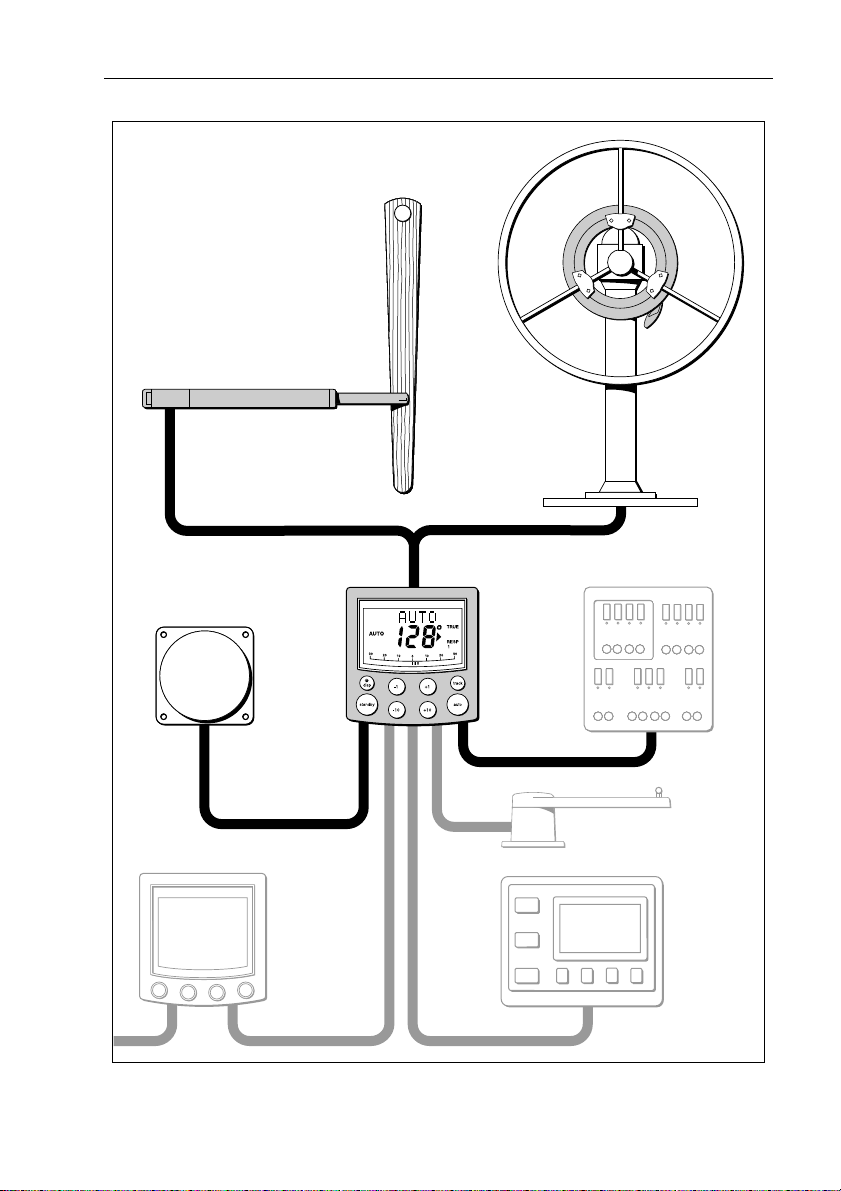
ST4000+ autopilot system layout
Wheel drive
OR
Tiller drive
Boat's electrical
distribution panel
Fluxgate compass
ST4000+
control unit
SeaTalk instrument
Rudder position sensor
(optional fit for wheel pilot only)
NMEA
instrument
or navigator
D5332-1
Page 5

iv ST4000+ Wheel & Tiller Autopilots: Owner’s Handbook
Page 6

Preface v
Contents
About this handbook ...........................................................ix
Important Information .........................................................x
Warranty ......................................................................................x
Safety notices ..............................................................................x
EMC conformance .....................................................................xi
Handbook information ...............................................................xi
Chapter 1: Introduction ............................................................1
1.1 Features .....................................................................................1
1.2 Extended systems ......................................................................2
Chapter 2: Basic Operation .......................................................3
2.1 Using the control unit ................................................................4
Key functions ............................................................................ 4
Display layout ...........................................................................5
2.2 Using Auto mode ......................................................................6
Engaging the autopilot (Auto mode) .........................................6
Disengaging the autopilot (Standby mode) ..............................7
Changing course in Auto mode .................................................8
Dodging obstacles in Auto mode ..............................................8
Returning to the previous locked heading (LAST HDG) ......... 9
Automatic tack (AutoT ack) .................................................... 10
Making major course changes ................................................ 10
Gusting conditions .................................................................. 11
2.3 Adjusting autopilot performance ............................................12
Changing the response lev el (AutoSeastate) ..........................12
Changing the rudder gain ........................................................13
2.4 Autopilot alarms .....................................................................14
Responding to alarms ..............................................................14
2.5 Adjusting display and keypad lighting ...................................18
Chapter 3: Advanced Operation ............................................19
3.1 Using Track mode ...................................................................20
Selecting Track mode .............................................................20
Exiting Track mode ............................................................. ....22
Cross track error ......................................................................22
Tidal stream compensation .....................................................23
W aypoint arrival and advanc e .................................................24
Dodges in Track m ode ............................................................ 25
Safety in Track mode .............................................................. 25
Page 7

vi ST4000+ Wheel & Tiller Autopilots: Owner’s Handbook
3.2 Using Wind Vane mode .......................................................... 27
Selecting Wind Vane mode ..................................................... 27
Exiting Wind Vane mode ........................................................28
Adjusting the locked wind angle .............................................28
Returning to the previous apparent wind angle
(LAST WND) .........................................................................28
Dodges in Wind Vane mode .................................................... 29
Wind shift alarm ......................................................................29
Using AutoT ack in W ind Vane mode ......................................30
Operating hints for Wind Vane mode ...................................... 30
3.3 Displaying data pages ............................................................. 31
Chapter 4: Maintenance & Fault Finding ..............................33
4.1 Fault finding ............................................................................34
4.2 General maintenance .............................................................. 36
Wheel drive ............................................................................. 36
Control unit .............................................................................38
EMC advice ............................................................................ 39
4.3 Product support ....................................................................... 40
Software version ..................................................................... 40
Chapter 5: Installing the ST4000+ ..........................................43
5.1 Planning the installation .........................................................44
Too ls required .........................................................................44
EMC installation guidelines ................................................... 46
5.2 Control unit .............................................................................48
Location ..................................................................................48
Mounting procedure ...............................................................49
Cable connectors .....................................................................51
Power supply connection ........................................................ 51
SeaTa lk connections ............................................................... 52
NMEA connections ................................................................ 53
5.3 Fluxgate compass ...................................................................55
Location ..................................................................................55
Mounting ................................................................................ 57
Connecting to the control unit ................................................. 58
5.4 Tiller drive (tiller pilots only) ..................................................59
Critical dimensions .................................................................59
Basic installation ..................................................................... 60
Installation accessories ........................................................... 61
Connecting to the control unit ................................................. 68
Page 8

Preface vii
5.5 Wheel drive (wheel pilots only) ..............................................70
Installation stages ....................................................................70
Drilling the spoke clamp holes ................................................71
Securing the wheel drive to the wheel .....................................74
Attaching the pedestal bracket ................................................ 75
Connecting to the control unit .................................................79
5.6 Rudder position sensor (wheel pilot option) ...........................81
Ensuring correct alignment .....................................................81
Securing the sensor to the boat ................................................83
Attaching the sensor to the tiller arm .......................................83
Checking alignment ................................................................84
Connecting to the control unit .................................................84
Chapter 6: Setting-up the ST4000+ ........................................85
6.1 Functional test ......................................................................... 86
Switch on ................................................................................86
Autopilot steering direction ....................................................86
Checking connections .............................................................88
6.2 Check rudder sensor operation (if fitted) ................................90
6.3 Initial sea trial .......................................................................... 91
Overview ................................................................................ 91
Correcting the compass deviation ..........................................92
Adjusting the heading alignment ............................................95
Checking autopilot operation ..................................................95
Checking the rudder gain ........................................................ 96
6.4 Autopilot calibration techniques .............................................98
Step 1 - Switch on ancillary equipment ...................................98
Step 2 - Apply initial settings ..................................................98
Step 3 - Adjust the rudder damping .........................................99
Step 4 - Adjust the rudder gain ................................................99
Step 5 - Adjust the AutoTrim setting .......................................99
Step 6 - Further adjustments ....................................................99
Chapter 7: Customizing the ST4000+ ..................................101
7.1 User setup ..............................................................................102
Compass deviation correction (SWING COMPASS) .......... 102
Deviation display (DEVIA TION) ........................................102
Heading alignment (ALIGN HDG) ......................................102
Heading mode (HDG MAG/TRU) .......................................102
Bar selection (RUDD BAR/STEER BAR/NO BAR) .......... 104
Data pages 1-7 (DA T A P AGE) ..............................................104
Page 9

viii ST4000+ Wheel & Tiller Autopilots: Owner’s Handbook
7.2 Dealer setup ..........................................................................106
Calibration lock (CAL LOCK) ............................................. 108
Pilot type (4000 WHL/TILL) ............................................... 108
Rudder gain (RUDD GAIN) .................................................108
Response level (RESPONSE) .............................................. 108
Turn limit (TURN RATE) ..................................................... 108
Rudder alignment (ALIGN RUD) ........................................ 108
Rudder limit (RUD LIMIT) .................................................. 109
Off course alarm (OFF COURSE) ........................................109
AutoTa ck angle (AUTOT AC K) ........................................... 109
AutoTrim (AUTOTRIM) ..................................................... 110
Drive type (DRIVE TYP) ..................................................... 110
Magnetic variation (VARIA TION) ....................................... 110
AutoAdapt (AUTOADAP T) .................................................111
Latitude (LA TITUDE) ...........................................................111
Rudder damping (RUDD DAMP) ........................................ 112
Cruise speed (CRUISE SP) .................................................. 112
Specifications .................................................................... 113
Glossary .............................................................................. 115
Index ................................................................................... 117
Page 10
Preface ix
About this handbook
W elcome to the handbook for the ST4000+ wheel and tiller
autopilot systems. Thi s handbook contains two main parts:
Part 1: Using the ST4000+ Autopilot
Chapter 1: Introduction
1
Introduces the autopilot, its features and its use.
Chapter 2: Basic Operation
Covers basic autopilot operation: using Auto mode,
2
interpreting alarms, adjusting autopilot performance and
changing the control unit lighting.
Chapter 3: Advanced Operation
Explains how to use Track and Wind Vane modes, and
3
display data pages.
Chapter 4: Maintenance & Fault Finding
Provides general maintenance procedures and
4
information to help you resolve problems you may
encounter with the autopilot
page 1
page 3
page 19
page 33
Part 2: Installing the ST4000+ Autopilot
Chapter 5: Installing the ST4000+
5
Explains how to install your autopilot and its components.
Chapter 6: Setting-up the ST4000+
Covers functional testing and dockside procedures after
6
installation, and initial sea trials.
Chapter 7: Customizing the ST4000+
Provides details on adjusting the autopilot settings to suit
7
your boat.
page 43
page 85
page 101
At the end of this h andbook we have included product
specifications, a glossary and index, and templates for installing
different part s of the syst em.
Note: T his handbook contains important information about
installing, using and maintainin g your new Raymarine product. To
get the best from the product, please read this h andbook thoroughly.
Page 11

x ST4000+ Wheel & Tiller Autopilots: Owner’s Handbook
Important Information
Warranty
T o register your new Raymarine product, please take a few minutes to
fill out the warranty card. It is important that you complete the owner
information and return the card to us to receive full warranty benefits.
Safety notices
WARNING: Product installation
This equipment must be installed and operated in accordance
with the instructions contained in this handbook. Failure to do so
could result in poor pr oduct performance, personal injury
and/or damage to your boat.
WARNING: Electrical safety
Make sure the power supply is switched off befor e you make any
electrical connections.
WARNING: Calibration
We supply th is product calibrated to default settings tha t should
provide stable performance for most boats. T o ensure op timum
performance on your boat, you mu st complete Chapter 6:
Setting-up the ST4000+ befor e use.
WARNING: Navigation aid
Although we have designed this pr oduct to be accurate and
reliable, many factors can affect its performance. As a result, it
should only be used as an aid to n avigation and should never
replace common s ense and navigational judgement. A lways
maintain a permanent watch so you can respond t o situations as
they develop.
Y our Raymarine autopilot will add a new dim ension to your boating
enjoyment. However, it is the skipper’s responsibility to ensure the
safety of the boat at all times by following these basic rules:
• Ensure that someone is present at the helm A T ALL TIMES, to
take manual control in an emergency .
Page 12

Preface xi
• Make sure that all members of crew know how to disengage the
autopilot.
• Regularly check for other boats and any obstacles to navigation –
no matter how clear the sea may appear, a dangerous situation can
develop rapidly.
• Maintain an accurate record of the boat’s position by using either
a navigation aid or visual bearings.
• Maintain a continuous plot of your boat’s position on a current
chart. Ensure that the locked autopilot heading will steer the boat
clear of all obstacles. Make proper allowance for tidal set – the
autopilot cannot.
• Even when your autopilot is locked onto the desired track using a
navigation aid, always maintain a log and make regular positional
plots. Navigation signals can produce signifi cant errors under
some circumstances and the autopilot will not be able to detect
these errors.
EMC conformance
All Raymarine equipment and accessories are designed to the best
industry standards for use in the recreational marine environment.
The design and manufacture of Raymarine equipment and
accessories conform to the appropriate Electromagnetic
Compatibility (EMC) standards, but correct installation is required to
ensure that performance is not compromised.
Handbook information
T o the best of our knowledge, the information in this handbook was
correct when it went to press. However, Raymarine cannot accept
liability for any inaccuracies or omissions it may contain. In addition,
our policy of continuous product improv ement may change
specifications without notice. As a result, Raymarine cannot accept
liability for any differences between the product and th e handbook.
Page 13

xii ST4000+ Wheel & Tiller Autopilots: Owner’s Handbook
Page 14

Part 1: Using the ST4000+
Part 1: Using the ST4000+
Page 15

Part 1: Using the ST4000+
Page 16
Chapter 1: Introduction 1
Chapter 1: Introduction
D5460-1
1.1 Features
The Raymarine ST4000 Plus (ST4000+) is a SeaT alk® compatible
autopilot available in versions suitable for boats with either tiller or
wheel steering systems. This autopilot system will st eer your boat to
a heading automatically, accurately and reliably .
The ST4000+ has four main operating modes:
1 Introduction
1.
Standby: autopilot off (see page 7)
2.
Auto: autopilot engaged and locked onto a heading (see page 6)
Track: autopilot engaged and maintaining a track between two
3.
waypoints created using a navigation sy stem (see page 20)
4.
Wind Vane: autopilot engaged and maintaining a course relative
to an apparent wind angle (see page 27)
The ST4000+ also provides the following features:
• automatic tack facility (AutoTack) in Auto and Wind V a ne modes
• automatic compass deviation correction
• Northerly/So utherly heading compens ation
• automatic heading deadband – seastate control
• waypoint advance feature
• setup and calibration options to optimize performance on your boat
Page 17

2 ST4000+ Wheel & Tiller Autopilots: Owner’s Handbook
1.2 Extended systems
The ST4000+ is compatible with all other SeaT alk instruments.
Y ou can connect it to additional fixed or handheld SeaTalk autopil ot
control units located at secondary steering and control positi ons
(see page 52).
1 Introduction
Y ou can also use the ST4 000+ autopilot with any navigator
(GPS, Decca, Loran) or wind instrument that transmits data in the
internationally-accepted National Marine Electronics Association
(NMEA) 0183 format.
The ST4000+ can display SeaT alk and NMEA instrument data in a
user-defined selection of data pages. When you are usin g the
ST4000+ to repeat instrument data, i t shows a ‘pop-up’ pilot page for
5 seconds whenever you make a change in autopilot control.
The ST4000+ can share all data transmitted from SeaT alk
instruments:
• it can use wind information from a SeaT alk wind instrument for
wind trim steering in Wind Vane mode without the need for a
separate vane
• it can use track information from a SeaT alk navigation instrument
to provide waypoint control in T rack mode
• it can use boat speed from a SeaTalk speed instrument to optimize
track-keeping performance
Rudder position sensor (wheel drives only)
On wheel drive systems you can fit a rudder position sensor to
improve the wheel pilot’s performance (see page 81). This is
particularly advisable if your boat’s steering system has significant
backlash, or you require optimum performance from a mechanical or
cable steering system. By using the information from the rudder angle
sensor, the ST4000+ will also be able to show the true rudd er angle in
Standby and Auto modes.
Note: Y ou MUST add a rudder positi on sensor if fitting the ST4000+
to a hydraulic steering system.
Page 18
Chapter 2: Basic Operation 3
Chapter 2: Basic Operation
The sections in this chapter explain how to use the basic functions on
your autopilot:
Using the control unit
2.1
2.2
2.3
2.4
2.5
Summarizes the key functions and screen layout on the
ST4000+ control unit.
Using Auto mode
Provides instructions for engaging/disengaging the
autopilot and using Auto mode.
Adjusting autopilot performance
Making temporary adjustments to response level and
rudder gain to enhance autopilot performance.
Autopilot alarms
Describes how to recognize and respond to the
autopilot alarms.
Adjusting display and keypad lighting
Explains how to change the lighting on the control unit
display and keypad.
page 4
page 6
page 12
page 14
page 18
2 Basic Operation
CAUTION: Important note for wheel drive systems
After each trip, flush inside the drive unit by inserting a hose pipe
in the free slot on the back cover . This will prevent any build-up of
salt on the drive ring and bearings.
Page 19

4 ST4000+ Wheel & Tiller Autopilots: Owner’s Handbook
2.1 Using the control unit
Key functions
• The autopilot always powers up in Stan dby mode.
• Y ou control the autopil ot by pressing the buttons on the control
unit. The control unit confirms each button press with a short
beep.
• Y ou access the main functions by pressing a sing le key:
• for example, when the autopilot is operating you can make
course changes using the
• T o access other functions you need to press two keys together:
• for example, when the autopilot is operating you make an
AutoTack to po rt by pressing the
• Y ou can return to manual steering at any t ime by pressing
standby and disengaging the autopilot (see page7).
2 Basic Operation
Press for Response level
-1 plus -10
Press together
for AutoTack
to port
-1, +1, -10 and +10 keys
-1 and -10 keys together
-1 plus +1
Press for 1 second
for Rudder Gain
+1 plus +10
Press together
for AutoTack
to starboard
DISP
Press for
Data Page
Press for 1 second
for lamp control
STANDBY
Press for
Standby mode
Press and hold for
User and Dealer
setup modes
Course change keys
Port 1˚ Starboard 1˚
Port 10˚ Starboard 10˚
STANDBY plus AUTO
Press for Wind Vane mode
Press for 1 second for Last Wind
Press again to accept Last Wind
TRACK
Press for Track
mode from Auto
Press to accept
waypoint advance
Press for 1 second
to skip waypoint
AUTO
Press for Auto mode
Press for 1 second
for Last Heading
Press again to
accept Last Heading
D3447-2
Page 20
Chapter 2: Basic Operation 5
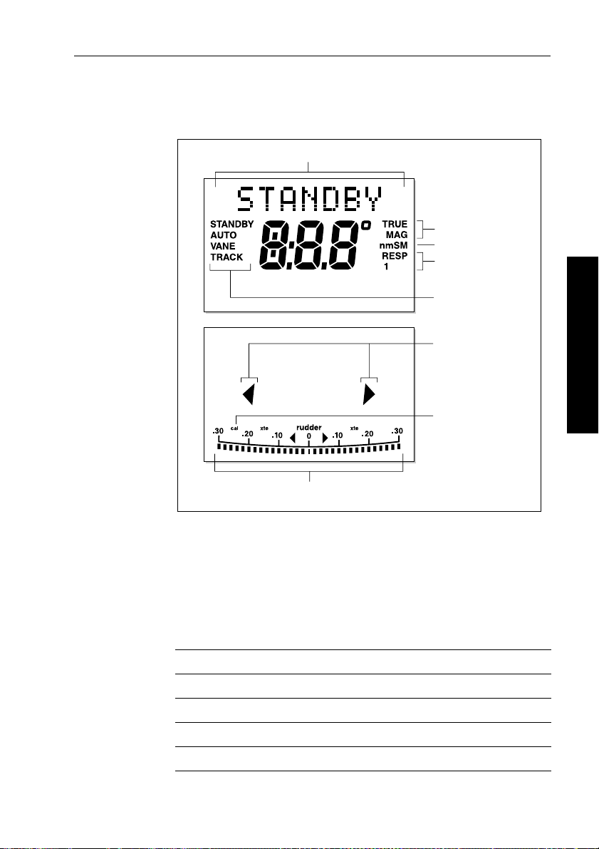
Display layout
The ST4000+ autopilot display provides t he following information:
Variable text region (up to 9 characters/digits)
Heading indicators
Distance units
Response level indicator
Autopilot mode
indicators
Port and Starboard
direction-to-steer
indicators
Calibration mode
indicator
Rudder or Steer direction indicator
(bar graph in 2˚ increments)
• If the display shows no distance unit all distances are in
kilometres (Km), otherwise distances are in nautical miles (nm
or statute/land miles (SM).
• The bar graph at the bottom of the screen is normally a
direction-to-steer indicator (you can change this in User setup,
see page 104). The information displayed on the bar graph varies
according to the autopilot mode:
Autopilot mode Information displayed on bar graph
Standby Rudder bar (only if a rudder position sensor is fitted)
2 Basic Operation
D3316-2
)
Auto Heading error bar
Track Cross track error (XTE) bar, in 0.02 nm increments
Wind Vane Wind angle error bar
Page 21
6 ST4000+ Wheel & Tiller Autopilots: Owner’s Handbook
2.2 Using Auto mode
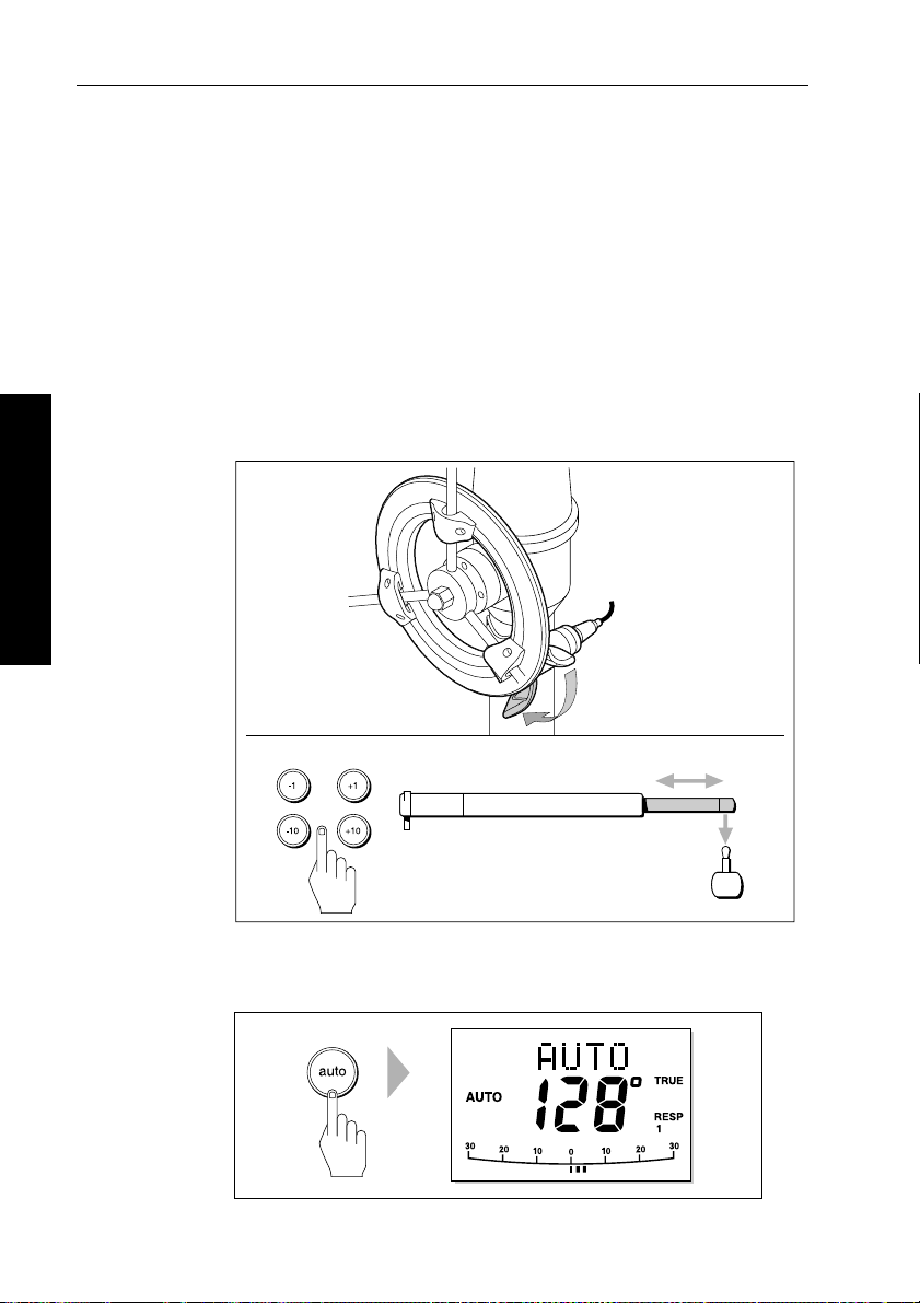
Engaging the autopilot (Auto mode)
1. Steady the boat on the required headi ng.
2. Wheel Pilot: Engage the wheel drive clutch by rotating the clutch
lever clockwise (so the lever engages full y onto the locating pip).
Tiller Pilot: Place the pushrod end over the tiller pin. If necessary,
extend or retract the pushrod using the
WARNING: Wheel drive clutch
Always reach AROUND (not through) the wheel to operate the
wheel drive clutch lever.
.
Wheel pilot
2 Basic Operation
-1, +1, -10 and +10 keys.
Engage the clutch
on the wheel pilot
Tiller pilot
Use these keys to
extend or retract the pushrod
a
3. Press auto:
• in Auto mode, the display shows the locked autopilot heading
b
D5341-1
D3560-2
Page 22
Chapter 2: Basic Operation 7
CAUTION:
Autopilot course control makes it easier to sail a boat, but it is
NOT a substitute for good seamanship. ALW A YS maintain a
permanent watch, no matter how clear the sea appears to be.
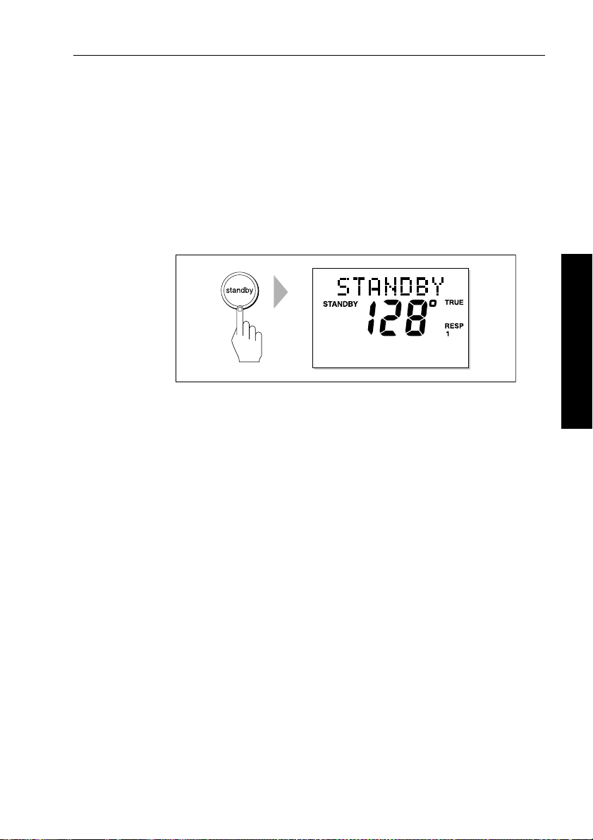
Disengaging the autopilot (Standby mode)
1. Press standby.
• in Standby mode, the display shows the boat’s c urrent
compass heading.
D3561-2
2. Disengage the autopilot to return to hand steering:
• Wheel Pilot: Disengage the wheel drive clutch by rotating the
clutch lever anti-clockwise (so the lever engages fully onto
the locating pip).
• Tiller Pilot: Remove the drive unit from the tiller pin. If
required, retract the push rod using
3. The last heading is memorized and can be recalled (see page 9).
-1, +1, -10 and +10 keys.
2 Basic Operation
CAUTION: Wheel drive systems
On wheel drive systems, always make sure that the clutch is
FULL Y DISENGAGED befor e you leave the boat.
Page 23
8 ST4000+ Wheel & Tiller Autopilots: Owner’s Handbook
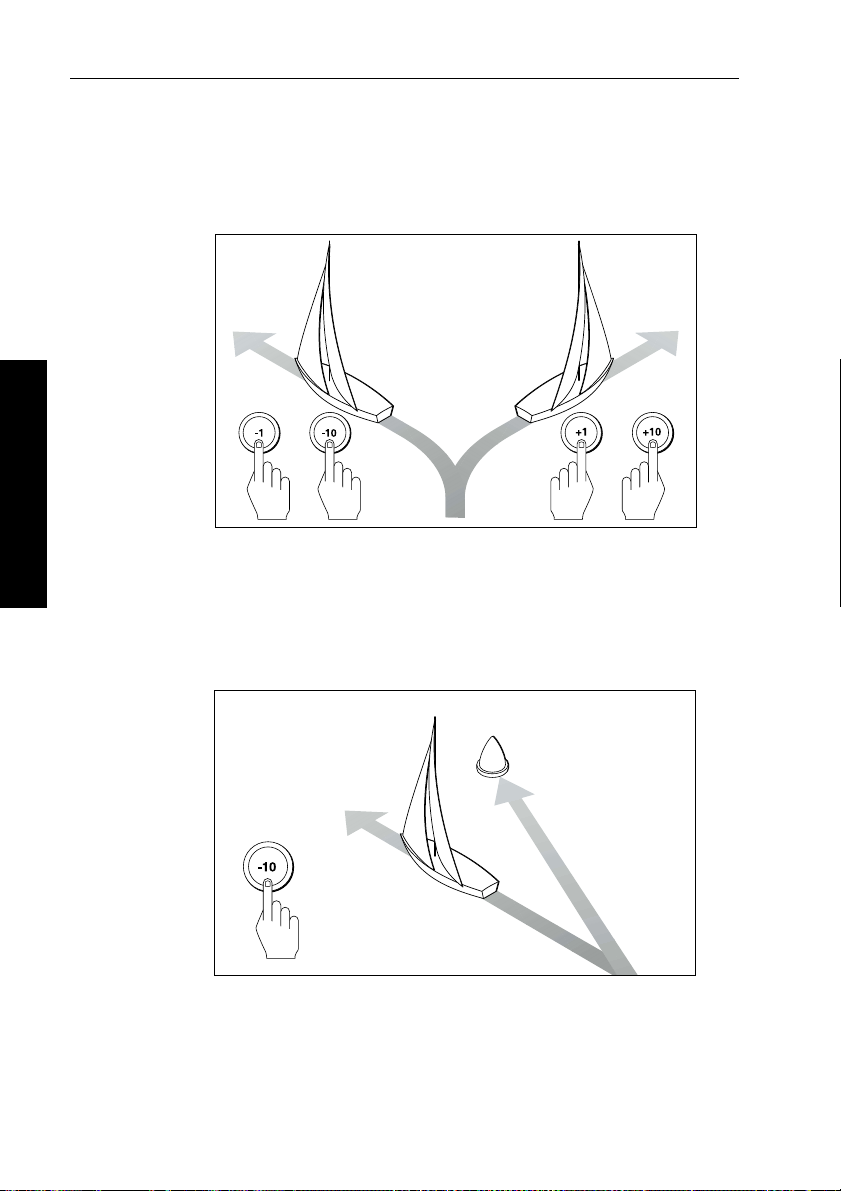
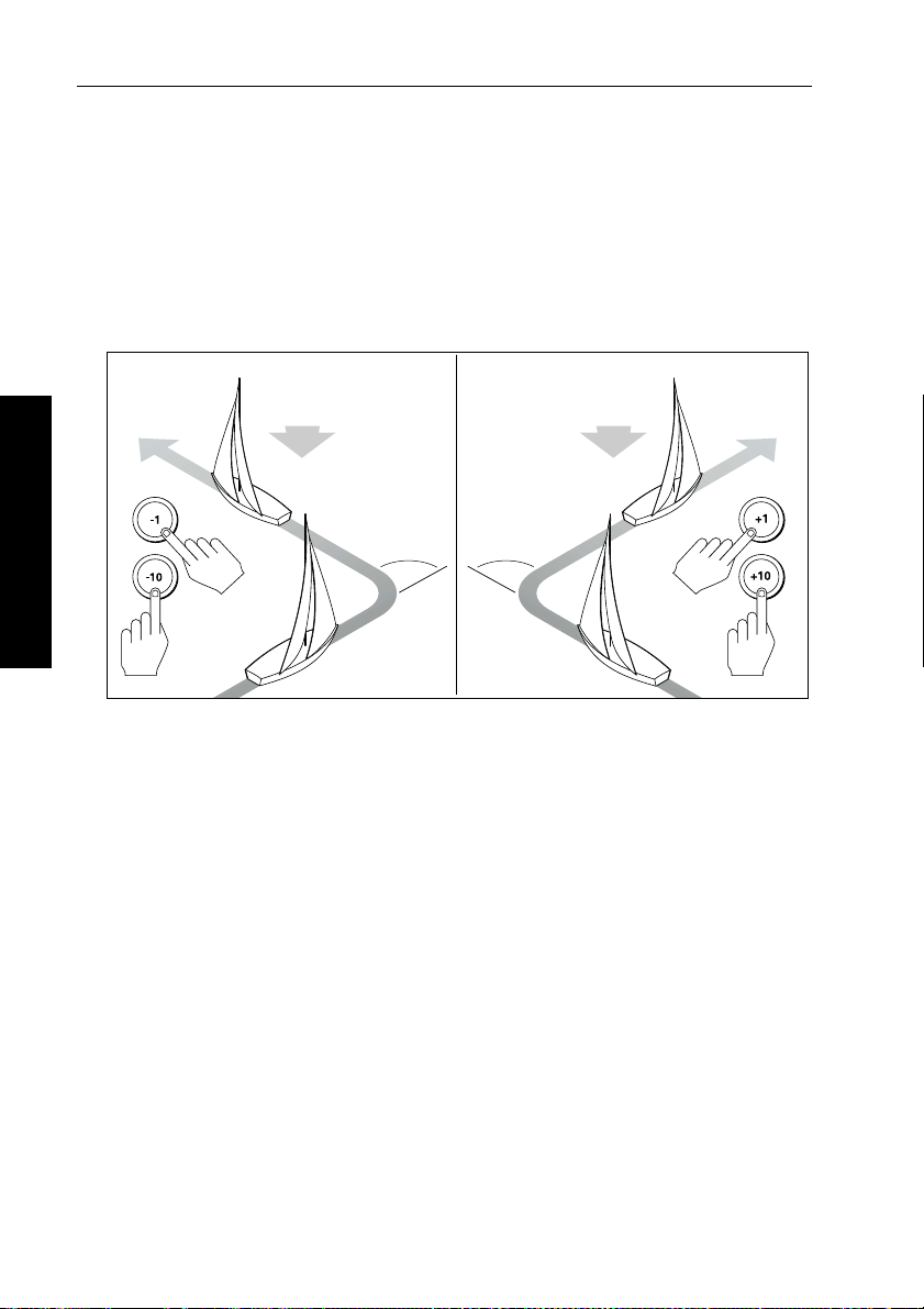
Changing course in Auto mode
In Auto mode, use the -1 and -10 (port) and +1 and +10 (starboard)
keys to change the locked heading in steps of 1° or 10°. For example:
press
-10 three times for a 30° course change to port.
Port Starboard
oror
2 Basic Operation
Dodging obstacles in Auto mode
T o avoid an obstacle when your boat is under autopilot control:
1. Select a course change in the appropriate direction. For exampl e,
press
-10 three times for a 30° dodge to port.
D3320-2
Obstacle
Original
course
Dodge
2. When safely clear of the obstacle, you can either:
• reverse the previous course change (for example, press
three times), or
• return to the previous locked heading (
LAST HDG)
D3303-2
+10
Page 24
Chapter 2: Basic Operation 9
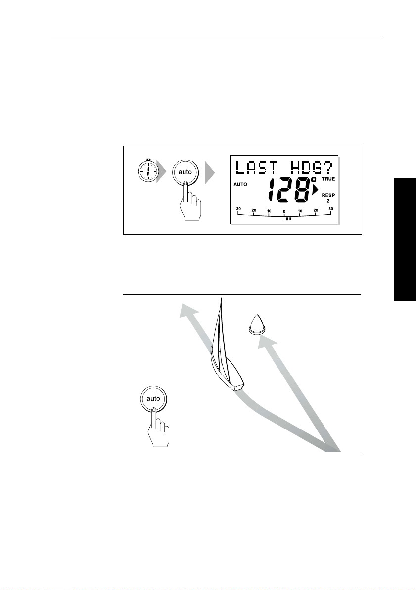
Returning to the previous locked heading (LAST HDG)
If you have steered the boat away from the selected locked heading
for any reason (for example, executing a dodge maneuver or selecting
Standby), you can return to the previous l ocked heading as follows:
1. Press
Note: T he direction-to-steer indicator shows the direction t he boat
will turn.
2. T o accept the previous heading, and resume this course, press
auto for 1 second. The display shows the prev ious locked
heading (
SECOND
LAST HDG?) for 7 seconds.
auto within this 7 second period.
D3562-2
2 Basic Operation
Obstacle
Resumed
course
Dodge
Note: If you do not press
auto while the display is flashing, the
autopilot will maintain the current heading.
Original
course
D5431-1
Page 25
10 ST4000+ Wheel & Tiller Autopilots: Owner’s Handbook
Automatic tack (AutoTack)
The ST4000+ has a built in automatic tack facility (AutoT ack) that
turns the boat through a pre-determined angle in the required
direction. The default AutoTack angle is 100°, but you can adjust this
in Dealer setup (see page 109).
• to AutoTack to port: press the
• to AutoTack to starboard: press the
AutoTack - Port
-1 and -10 keys together
+1 and +10 keys together
AutoTack - Starboard
Wind
AutoTack
angle
AutoTack
angle
Wind
2 Basic Operation
D5399-1
Making major course changes
CAUTION:
Only make major course changes when steering MANUALL Y .
This ensures that the boat wil l safely clear any obstructions or
other boats, and you can take into account the changed wind and
sea conditions on the new heading before engaging the autopilot.
Large course changes which change the apparent wind direction can
produce large trim changes. When a sudden trim change occurs (for
example due to weather helm or sail imbalance) there will be a delay
of up to one minute before the automatic trim applies rudder to restore
the locked heading.
In these situations, the autopilot will not immediately assume the new
automatic heading, and will only settle onto course when the
automatic trim has been fully established. To eliminate this problem,
use the following procedure to make major course changes:
Page 26

Chapter 2: Basic Operation 11
1. Note the required new heading.
2. Select
3. Select
standby for manual steering, so you can bring th e boat to
the new heading MANUALLY.
auto: allow the boat to settle onto course, then bring the
boat to the final course in 1° steps using the
-1 or +1 keys
Gusting conditions
In gusting conditions, the course may tend to wan der slightly ,
particularly if the sails are badly balanced. If you take the following
precautions, the autopilot will be able to maintain competent control
even in gale force conditions:
• Y ou can signifi cantly improve course keeping by improving the
sail balance:
• do not allow the boat to heel over excessively
• ease the mainsheet traveller to leeward to reduce heeling and
weather helm
• if necessary, reef the mainsail a little early
• In very strong winds and lar ge seas, you should avoid sailing with
the wind dead astern:
• ideally, bring the wind at least 30° away from a dead run
• in severe conditions, you may also need to r emove the
mainsail and sail under headsail only
2 Basic Operation
Page 27
12 ST4000+ Wheel & Tiller Autopilots: Owner’s Handbook
2.3 Adjusting autopilot performance
During normal autopilot operation in any mode you can make
temporary adjustments to:
• response level
• rudder gain
Note: Y ou will lose these temporary changes to response level and
rudder gain whenever the system is powered off then on again. You
can make permanent adjustments in Dealer setup ( see page 108).
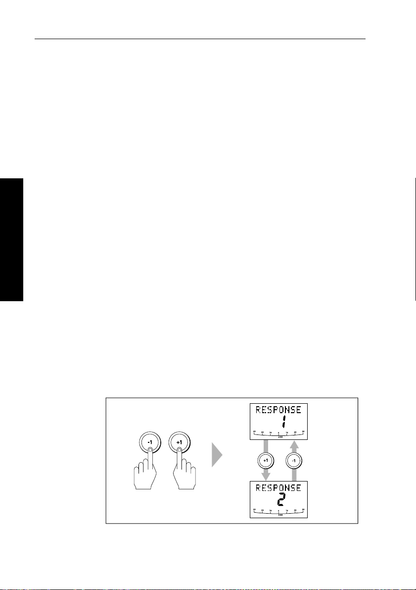
Changing the response level (AutoSeastate)
The response level controls the relationship between the autopilot’s
course keeping accuracy and the amount of helm/drive activity .
• Response Level 1: AutoSeastate on ( Automatic deadband)
This setting causes the autopilot to gradually ignore repetitive
2 Basic Operation
boat movements and only react to true variations in course. This
provides the best compromise between power consumption an d
course keeping accuracy , and is the default calibration setting.
• Response Level 2: AutoSeastate off (Minimum deadband)
This setting provides the tightest course keep ing possible.
However, tighter course keeping results in increased power
consumption and drive unit activity .
To make a temporary change to the response setting:
1. Display the
RESPONSE screen by pressing the -1 and +1 keys
together momentarily .
D3310-4
Page 28
Chapter 2: Basic Operation 13
Note: If you h ave set up the RESPONSE screen as a default data page
(see page 104) you can also access it by pressing
disp and then
scrolling through the data pages .
2. Press
3. Press
-1 or +1 to change the response level.
disp or wait for 5 seconds to return to the pr evious display .
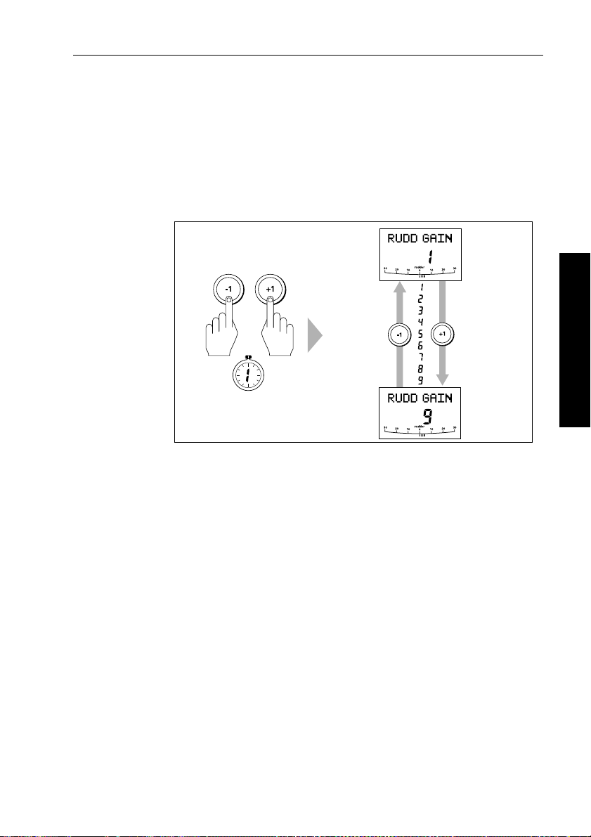
Changing the rudder gain
SECOND
To make a temporary change to the rudder gain:
1. Press the
rudder gain (
Note: If you have set up the
(see page 104) you can also access it by pressing
scrolling through the data pages .
2. Press
3. Press
Note: S ee page 96 for instructions on how to check that the rudder
gain is set correctly.
-1 and +1 keys together for 1 second to display the
RUDD GAIN) screen
-1 or +1 to change the rudder gain.
disp or wait for 5 seconds to return to the pr evious display .
Decrease
rudder gain
Increase
rudder gain
D5400-1
RUDD GAIN screen as a default data page
disp and then
2 Basic Operation
Page 29
14 ST4000+ Wheel & Tiller Autopilots: Owner’s Handbook
2.4 Autopilot alarms
Responding to alarms
The ST4000+ activates the alarms listed on the following pages:
• Unless otherwise stated, you should deal with alarms by pressing
standby to clear the alarm and return to hand steering.
• In some situations, the autopilot will raise more than one alarm.
When you have dealt with the first alarm, the autopilot will
display the next alarm.
SeaTalk Failure alarm (STLK FAIL)
The ST4000+ displays the SeaT alk failure message if there is a wiring
fault in the SeaTalk connection.
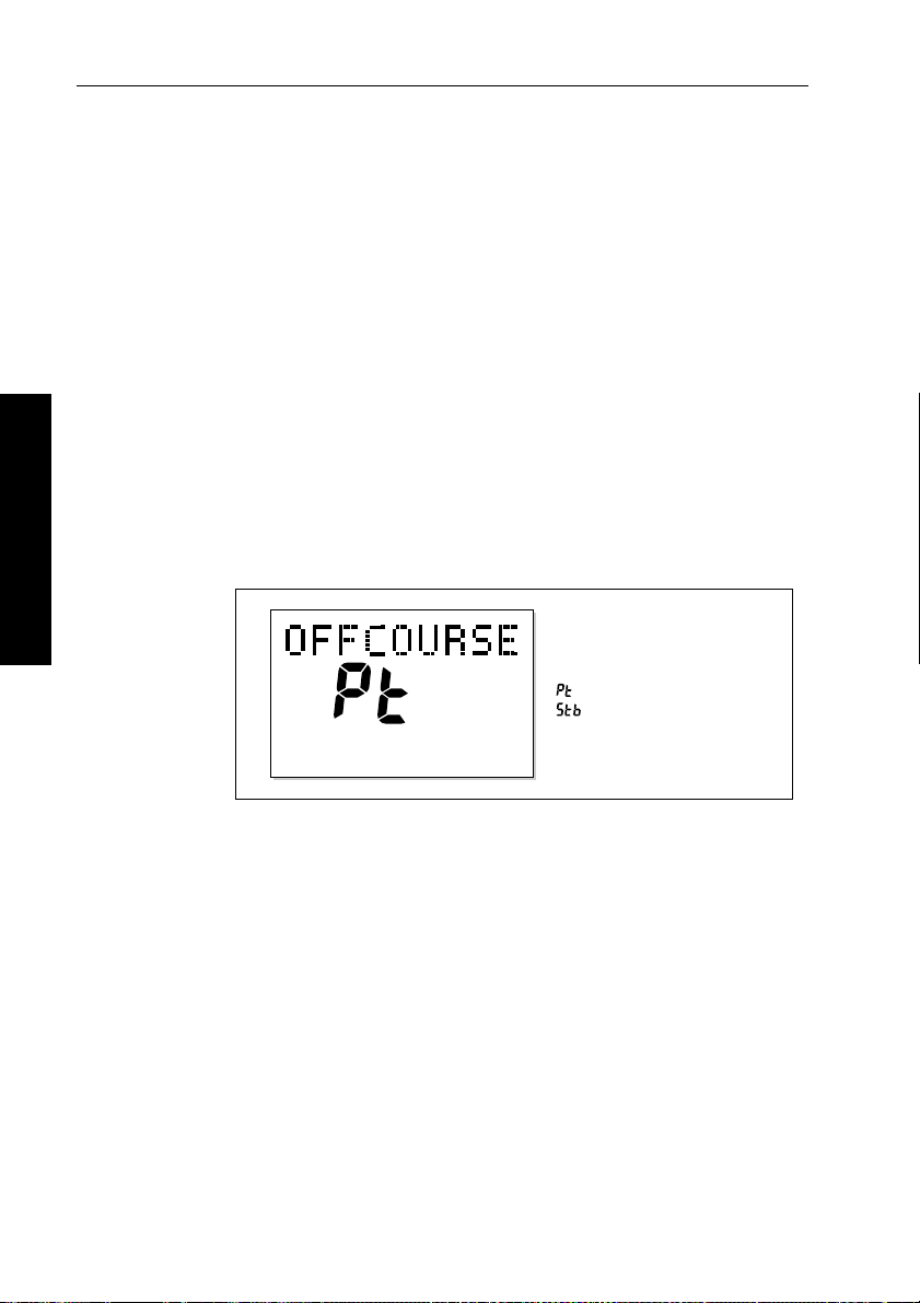
Off Course alarm (OFFCOURSE)
2 Basic Operation
= deviation to port
= deviation to starboard
D3315-2
The ST4000+ activates this alarm when the boat has been off course
from the locked heading by more than the specified angle* for longer
than 20seconds. It shows whether the deviation is to port or starboard.
Note: * Y ou can adjust this specified alarm angle in Deal er setup
(see page 109).
1. T o cancel the off course alarm, press
standby to return to hand
steering.
2. Check whether your boat is carrying too much sail, or whether the
sails are badly balanced. Y ou can usually signif icantly improve
course keeping by improving the sail balance.
Note: T he ST4000+ also clears the alarm if the heading recover s, if
you change the course, or if you change the operating mode.
Page 30

Chapter 2: Basic Operation 15
Wind Shift alarm (WINDSHIFT)
The ST4000+ activates the W indshift alarm when it detects a change
in the apparent wind angle of more than 15° (see page 29).
Large Cross Track Error alarm (LARGE XTE)
The ST4000+ activates this alarm when the cross track error exceeds
0.3 nm (see page 22).The alarm clears if the heading recovers, if you
change the course, or if you change the operating mode.
Drive Stopped alarm (DRIVESTOP)
The ST4000+ activates this alarm if:
• the rudder position sensor fails, or
• the autopilot is unable to turn the rudder (this occurs if the weather
load on helm is too high, or if the rudder position s ensor has
passed beyond the preset rudder limits or rudder end-st ops)
Data Not Received alarm (NO DATA)
The ST4000+ activates this alarm in any of the following situations:
• the compass is not connected
• the autopilot is in Wind Vane mode and it has not received wind
angle data for 30 seconds
• the autopilot is in Track mode and:
• the boat has arrived at the last waypoint in the track, or
• the autopilot is not receiving SeaT alk navigation data, or
• the position sensor (GPS, Loran, Decca) is receiving a low
strength signal – this will clear as soon as the sign al strength
improves
The autopilot stops adjusting the heading as soon as it loses data.
2 Basic Operation
Waypoint Advance alarm (NEXT WPT?)
The ST4000+ activates the W aypoint Advance alarm whenever the
target waypoint number changes. Thi s occurs when:
• you select automatic acquisition by pressing
• you request waypoint advance by pressing
Track mode (with SeaT alk navigators onl y)
track from Auto
track f or 1 second in
Page 31

16 ST4000+ Wheel & Tiller Autopilots: Owner’s Handbook
• the boat arrives at the target waypoint and the navigator accepts
the next waypoint
• you activate the Man Overboard (MOB) function in Track mode
When the alarm sounds, the pilot continues on its current heading but
displays:
• the bearing to the next waypoint
• the direction the boat will turn to take up that bearing
Responding to a Waypoint Advance alarm
T o respond to a W aypoint Advance alarm:
• check that it is safe to turn onto the new track, then press
accept the waypoint advance
• alternatively, you can cancel the alarm without accepting the
waypoint advance by pressing:
steering, or
2 Basic Operation
Note: W aypoint advance only operates if the ST4000+ is receiving
valid bearing to waypoint and waypoint n umber information.
auto to return to Au to mode.
standby to return to hand
track to
Low Battery alarm (LOW BATT)
The ST4000+ activates the Low Battery alarm when the supply
voltage drops below 10 V (±0.5 V).
Responding to a Low Battery alarm:
T o respond to a Low Battery alarm:
• press
• start the engine to recharge the battery
standby to clear the alarm and return to hand steering
Watch alarm (WATCH)
The ST4000+ activates the W atch alarm when the autopilot is in
W atch mode and the timer has reached 4 minutes.
Setting the Watch timer
T o set the Watch timer:
1. First, you must configure the
pages for display (see page 104).
2. When you have done this select Auto, T rack or Wind Vane mode.
WATCH screen as one of the data
Page 32

Chapter 2: Basic Operation 17
3. Press the disp key until you see the WATCH data page:
• the watch timer will start counting
• when the timer reaches 3 minutes, the
flashing to indicate that the timer is in the last minute
• when the timer reaches 4 minutes, the ST4000+ activates the
audible W atch alarm
Responding to a Watch alarm
T o respond to a W atch alarm:
WATCH text star ts
• press
• press any other key to silence the alarm, reset the timer and
Note: Y ou cannot engage Auto mode directly from Watch mode –
pressing
Auto mode, you must first exit Watch mode (see below).
Exiting Watch mode
T o exit Watch mode:
• press
• press
auto to silence the alarm and reset the timer to 4 minutes
or
perform that key’s normal function
auto will onl y reset the Watch timer. If you want to enter
disp to displa y a different data page
or
standby
Shallow alarm (SHALLOW)
The ST4000+ activates the Shallow alarm if it receives a shallow
depth alarm via SeaT alk:
• press
standby or disp to cancel the alarm
Man Overboard alarm (MOB)
The ST4000+ activates the Man Overboard alarm if it receives a man
overboard (MOB) message from another instrument on the SeaT alk
system. It displays the text
the
XTE, DTW and BTW data pages.
If the autopilot is in T rack mode, it will sound the W aypoint Advance
alarm to notify you of the change in waypoint.
MOB instead of the waypoint number for
2 Basic Operation
Page 33

18 ST4000+ Wheel & Tiller Autopilots: Owner’s Handbook
2.5 Adjusting display and keypad lighting
Note: When the display lighting is off, the control unit still illuminates
the keys at a courtesy level.
T o adjust the display and keypad lighting:
1. Press
2. Press the
Note:
.
2 Basic Operation
disp for 1 second from any mode to access the LAMP screen
and turn on the lights.
disp key to cycle through the poss ible illumination
settings:
LAMP 3, LAMP 2, LAMP 1, OFF, LAMP 1, LAMP 2, LAMP 3
and so on.
LAMP 3 is the brightest setting.
SECOND
D3313-3
3. The display automatically returns to the previ ous mode if you do
not press a key for 7 seconds:
• if you press another mode key within 7 seconds you will select
the mode assigned to that key (for example:
mode,
standby selects St andby mode)
auto selects Auto
Note: You can als o adjust the lighting level from any other SeaTalk
instrument or control unit connected to SeaTalk.
Note: W hen you switch off the unit you lose any changes you have
made to the lighting.
Page 34

Chapter 3: Advanced Operation 19
Chapter 3: Advanced Operation
The sections in this chapter explain how to use the more advanced
functions on your autopilot:
Using Track mode
3.1
3.2
3.3
Tracking between waypoints created on navigation
equipment connected to the autopilot system.
Using Wind Vane mode
Using the autopilot to maintain a course relative to the
apparent wind angle.
Displaying data pages
Describes how to use d ata pages to display SeaTalk and
NMEA information on the control unit.
page 20
page 27
page 31
3 Advanced Operation
Page 35

20 ST4000+ Wheel & Tiller Autopilots: Owner’s Handbook
3.1 Using Track mode
Note: Y ou can only use Track mode if you have connected the
ST4000+ to a suitable navigation sy stem providing SeaTalk or
NMEA navigation information.
The ST4000+ can receive track and cross track error information
from either:
• a SeaT alk navigation instrument or chartplotter (see page 52 for
information on connecting to SeaT alk)
or
• a non-SeaT alk navigation system transmitti ng data in the
NMEA 0183 format – you can connect this directly to the
ST4000+ NMEA input (see page 53 for information on
connecting to NMEA equipment)
In Track mode, the ST4000+ maintains a track between two
waypoints created on the navigation system. The autopilot computes
any course changes to keep your boat on track, automatically
compensating for tidal streams and leeway.
Selecting Track mode
3 Advanced Operation
T o select Track mode, press the track key with the autopilot in Auto
mode.
When you select Track mode, the autopilot can acquire a track
through either:
• automatic acquisition (see below), when both cross track error
(XTE) and bearing to waypoint (BTW) data are available
or
• manual acquisition (see page 21), when only cross track error
information is available
Automatic track acquisition
If cross track error and bearing to waypoint information are both
available (via SeaTalk or NMEA), the autopilot can acquire a track
automatically:
1. Bring the boat within 0.1 nm of track.
2. Press
3. Press
auto. The autopilot will display the current locked heading.
track to enter Track mode.
Page 36

Chapter 3: Advanced Operation 21
4. W ait for the W aypoi nt Advance alarm to sound. The display will
show the bearing to the next planned waypoint and the direction
the boat will turn to reach this waypoint.
Note: If the boat is more than 0.3 nm from the track, the Larg e Cross
Track Error alarm will sound (see page22). Press
cancel the alarm, hand steer closer to the track, press
press
track.
standby to
auto and then
5. Check that it is safe to turn the boat onto th e new course.
6. Press the
track key:
• the boat will turn onto the new course
• the display shows the new bearing to waypo int
Automatic track acquisition
From auto mode, press track to enter Track mode: Then press track again to turn boat to waypoint:
Waypoint
at 270˚
Waypoint
at 270˚
Current
heading
Previous
heading
D5414-1
Manual track acquisition
If your navigation system only prov ides cross track error information,
you must acquire the track manually:
1. Steer the boat to within 0.1 nm of track.
2. Brin g the heading to within 5° of the bearing to the next wa ypoint.
3. Press
4. Press
auto.
track to enter T rack mo de. The d isplay then shows the
locked pilot heading.
3 Advanced Operation
Page 37

22 ST4000+ Wheel & Tiller Autopilots: Owner’s Handbook
Note: Tidal streams have a far more significant effect at lower sp eeds
than at higher speeds. If the tidal flow is less than 35% of the boat’s
speed, you will not notice any difference in the autopilot’s
performance in Track mode. However, you should take extra care
during manual acquisition, as fo llows:
• Before you select T rack mode, make sure t he boat is as close as
possible to track, and the dir ection made good over the gr ound is
as close as possible to the dir ection of the next waypoint.
• Make positive checks of the boat’s position at regular intervals,
especially if you are close to pot ential navigational hazard s.
Exiting Track mode
Y ou can return to either Auto or S tandby mode from T rack mode by:
• pressing
• pressing
auto to ret urn to Auto mode
standby to return to manual steering
Cross track error
Cross track error (XTE) is the distance between the current position
and a planned route. The autopilot receives the cross track error
information from the navigation equipment, and displays the XTE in
nautical miles (
nm), statute miles (SM) or kilometres.
3 Advanced Operation
Actual route
Waypoint 1
Planned route
Cross track error (XTE)
more than 0.3 nm
Waypoint 2
D5415-1
Page 38

Chapter 3: Advanced Operation 23
If the cross track error is greater than 0.3 nm, the ST4000+ will sound
the Large Cross T rack Error alarm and shows whether you are to the
port
(Pt) or starboard (Stb) of the planned track.
T o cancel the Large Cross Track Error alarm:
• press
• press
standby to return to hand st eering, or
auto to return to Au to mode a nd retain t he current heading
Note: W hen the Large Cross Track Error alar m sounds, it usually
means that the cross tide is too great for your boat’s current speed.
Tidal stream compensation
Under most conditions, Track mode will hold the selected track to
within ±0.05 nm (300 ft) or better.The autopilot takes account of the
boat’s speed when computing course changes t o ensure optimum
performance over a wide range of boat speeds. In order o f preference,
the ST4000+ uses:
• measured boat speed (speed through water)
• if this is not available, it uses the speed over ground (SOG)
• if this is not available, it uses the cruise speed specified in Dealer
setup (see page 112)
Waypoint 2
3 Advanced Operation
Boat's speed over ground
Waypoint 1
Tidal component
Boat's speed through water
D3261-2
Page 39

24 ST4000+ Wheel & Tiller Autopilots: Owner’s Handbook
Waypoint arrival and advance
Arrival
As the boat arrives at the target waypoint the navigation ai d should
manually or automatically select the next target waypoint. The
ST4000+ will then detect the new target waypoint number, sound the
W aypoint Advance alarm and display the W aypoint Advance screen.
This shows the new bearing to the next waypoint and the direction the
boat will turn to acquire the new track.
Advance
When the ST4000+ sounds the W aypoint Advance alarm, it suspends
Track mode and maintains the current boat heading.T o advance to the
next waypoint:
1. Check that it is safe to turn onto the new track.
2. Press the
alarm and turn the boat towards the next waypoint.
track key . This wi ll cancel the W aypoint Advance
3 Advanced Operation
Target
waypoint
Note: If you do not press
track to accept the Waypoint Advance, the
ST4000+ will maintain the current heading and co ntinue sounding
the alarm.
Waypoint arrival and advance
Waypoint arrival Waypoint advance
Next target
waypoint at 270˚
Old target
waypoint
New target
waypoint at 270˚
D5416-1
Page 40

Chapter 3: Advanced Operation 25
Note: W hen you reach the last waypoint in the track, the NO DATA
alarm will sound to indicate t hat there is no further waypoint
information. Press
standby to r eturn to hand steering.
auto to conti nue on the same heading, or
Skipping a waypoint – SeaTalk navigators only
If you want to advance to the next waypoint before you have arrived
at the target waypoint, you can skip a waypoin t by pressing
1 second. The display will then show the W aypoint Advance screen
for the next waypoint.
track for
Dodges in Track mode
When the autopilot is in Track mode you still have full control from
the keypad.
Initiating a dodge maneuver
In Track mode, you can make a dodge maneuver by u sing the course
change keys (
Cancelling a dodge maneuver
After you have avoided the hazard, you can cancel the dodge course
change by making an equal course change in the opposite direction.
Note: Pr ovided the boat remains within 0.1 nm of track, you do not
need to steer back towards the track.
-1, +1, -10 or +10) to select the desired course change.
3 Advanced Operation
Safety in Track mode
WARNING:
T rack mode provides accurate track keeping even in complex
navigational situations. However, it is still the skipper’s
responsibility to ensur e the safety of their boat at all times
through care ful navigation and fr equent position checks.
Sailing in Track mode assi sts precise navigation and removes the
tasks of compensating for wind and tid al drift. However , you MUST
still maintain an accurate log with regular plots.
Page 41

26 ST4000+ Wheel & Tiller Autopilots: Owner’s Handbook
Confirming position at the start of a journey
At the start of a journey you must always use an easily identifiable
fixed object to confirm the fix given by the navigation system. Check
for fixed positional errors and compensate for them.
Verifying computed positions
Always verify the computed position with a dead reckoned positio n,
calculated from the average course steered and the distance logged.
Plot frequency
• In open water, y ou should make plots at least every hour .
• In confined waters or when near to potential hazards, you should
make plots more frequently .
Setting waypoints
• Local variations in radio signal quality and changes in the tidal
stream can produce deviations from the desired track. When
setting waypoints, remember that deviations can occur.
• Thoroughly check along each track. Check up to 0.5 nm each side
of the track to ensure that there are no hazards within this zone.
3 Advanced Operation
Note: For the waypoint advance function to work, the last four
characters of adjacent waypoint names must be different.
Page 42

Chapter 3: Advanced Operation 27
3.2 Using Wind Vane mode
Note: Y ou can only use Wind Vane mode if you have connected the
ST4000+ to a suitable wind inst rument/vane providing SeaTalk or
NMEA wind direction informati on.
T o use Wind Vane mode (also known as V ane mode), t he ST4000+
must receive wind information from one of the followi ng sources:
• SeaT alk wind instrument, connected to the ST4000+ via SeaT alk
• NMEA wind instrument
• Raymarine wind vane connected through a SeaTalk interface box
In Wind Vane mode the ST4000+ maintains a course relative to an
apparent wind angle. It uses wind trim to eliminate the effects of
turbulence and short term wind variati ons. This provides smooth and
precise performance with minimal power consumption.
When the ST4000+ is in Wi nd V ane mode it uses the fluxgate
compass as the primary heading reference. As changes in the
apparent wind angle occur, the ST4000+ adj usts the locked compass
heading to maintain the orig inal appar ent wind an gle.
Selecting Wind Vane mode
Y ou can select W ind Vane mode from either Standby or Auto mode:
1. Steady the boat onto the requi red apparent wind angle.
2. Press
standby and auto together to select Wind V ane mode and
lock the current apparent wind angle:
• the display shows the locked heading (e.g.
the apparent wind angle (e.g.
WIND 145P indicates an apparent
128°) along with
wind angle of 145° to port)
3 Advanced Operation
The ST4000+ will then adjust the boat’s heading to maintain the
locked apparent wind angle.
D3565-2
Page 43

28 ST4000+ Wheel & Tiller Autopilots: Owner’s Handbook
Exiting Wind Vane mode
Y ou can return to Auto or Standby mode from W ind V ane mode by:
• pressing
• pressing
auto to ret urn to Auto mode
standby to steer manually in S tandby mode
Adjusting the locked wind angle
Y ou can adjust the locked wind angle by using the -1, +1, -10 and +10
keys to change course. For example, to bear away by 10° when th e
boat is o n a star board ta ck:
3 Advanced Operation
• press
-10 to turn the boat 10° to port – the locked apparent wind
angle and locked heading will both change by 10°
• the autopilot will then adjust the locked heading as required to
maintain the new apparent wind angle
Note: Becaus e turning the boat affects the relationship between the
true and apparent wind angles, you shoul d only use this method to
make minor adj ustments to the apparent wind angle. For maj or
changes, return to Standby mode, steer onto the new heading, t hen
reselect Wind Vane mode.
Returning to the previous apparent wind angle (LAST WND)
If you have steered the boat away from the selected apparent wind
angle for any reason (such as a dodge maneuver or selecting Standby
mode), you can return to the previous locked wind angle:
1. Press
standby and auto tog ether for 1 second to display the
previous apparent wind angle (
• the
LAST WND? text alternates with the previous wind angle
LAST WND?):
and direction. The display shows the previo us locked heading
and indicates which direction the boat will turn
SECOND
D3566-2
Page 44

Chapter 3: Advanced Operation 29
2. Check that it is safe to turn onto this course.
3. T o accept this apparent wind angle, press
together within 7 seconds.
Note: If you d o not accept the previous wind within 7 seconds, the
autopilot will lock onto the current apparent wind angle.
standby and auto
Dodges in Wind Vane mode
When the autopilot is in Wi nd V ane mode you s till have full control
from the keypad.
Initiating a dodge maneuver
In Wind Vane mode, you can make a dodge maneuver by using the
course change keys (
change. The autopilot will adjust both the locked heading and locked
apparent wind angle.
Cancelling a dodge maneuver
After you have avoided the hazard, you can reverse the previous
course change, or return to the previous wind angle (
-1, +1, -10 or +10) to select the desired course
LAST WND?).
Wind shift alarm
If the autopilot detects a wind shift of more than 15° it will sound the
wind shift alarm and display the
page 15).
• T o cancel the alarm and retain the existing wind angle and new
heading:
• press
• Alternatively, to cancel the alarm and return to the previous
heading, either:
• adjust the locked wind angle using the
+10 keys
or
• press
required heading, and press
return to Wind Vane mode with the new apparent wind angle
3 Advanced Operation
WINDSHIFT alarm message (see
standby and auto together.
-1, +1, -10 and
standby to return to hand steering, steer onto the
standby and auto to gether to
Page 45

30 ST4000+ Wheel & Tiller Autopilots: Owner’s Handbook
Using AutoTack in Wind Vane mode
After using the AutoT ack function (see page 10) to tack in Wind V ane
mode, you may need to adjust the locked heading until you achieve
the required apparent wind angle.
Note: Bef ore you use the AutoTack function in Wind Vane mode, you
must make sure that the wind vane was centered accurately at
installation.
Apparent wind angle
After tacking, you may need to make
minor course changes to achieve the
desired apparent wind angle
AutoTack
angle
3 Advanced Operation
AutoTack to Port
Operating hints for Wind Vane mode
• Always trim your sails carefully to minimize the amount of
standing helm.
• Reef the headsail and mainsail a little early rather than too late.
• In Wind Vane mode the pilot will react to long-term wind shifts,
but will not correct for short-term changes such as gusts.
• In gusty and unsteady inshore condi tions, it is best to sail a few
degrees further off the wind so that changes in apparent wind
direction can be tolerated.
D4373-2
Page 46

Chapter 3: Advanced Operation 31
3.3 Displaying data pages
Use the disp key to show ‘data pages’ of SeaT alk or NMEA data:
1. Press
2. Select the data page you want to use as the principle display o n the
Three data pages are set in the factory as a default (see diagram).
Within User setu p you can select up to seven pages and control the
information they display (see page 104):
• if the autopilot system cannot obtain the required information for
• the ‘direction-to-steer’ arrows relate to the data page information
• most data pages show repeated data so you cannot adjust them:
Default data pages
disp to access the first data page, and press it again to cycle
through each data page in turn:
• to return to a previous data page, press
disp for 1 second
within 2 seconds of displaying a page
• when you cycle past the last data page, the display returns to
the current autopilot mode screen (for example, Auto)
control un it:
• the current autopilot mode is shown at the left of the displ ay
and the autopilot bar graph remains in use
• if you then select a new mode or make a course change, the
autopilot mode screen appears as a ‘pop-up’ for 5 seconds
a data page, the display will show dashes instead of a value
the exceptions are the
RESPONSE and RUDDER GAIN data pages
(if you have selected them for display) which you can adjust
using the
-1 and +1 keys
3 Advanced Operation
Autopilot mode
Data page 2
Data page 1Data page 3
D3314-2
Page 47

32 ST4000+ Wheel & Tiller Autopilots: Owner’s Handbook
3 Advanced Operation
Page 48

Chapter 4: Maintenance & Fault Finding 33
Chapter 4: Maintenance & Fault Finding
This chapter provides information about identif ying common
problems, maintaining your autopilot syst em and obtaining product
support:
Fault finding
4.1
4.2
4.3
This section provides a checklist to help you identify
and resolve common autopilot problems.
General maintenance
This section explains how to maintain your autopilot
system.
Product support
This section outlines the product support available
from Raymarine worldwide.
page 34
page 36
page 40
4 Maintenance & Fault Finding
Page 49

34 ST4000+ Wheel & Tiller Autopilots: Owner’s Handbook
4.1 Fault finding
All Raymarine products are designed to provide many years of
trouble-free operation. W e also put them through comprehensive
testing and quality assurance procedures befo re shipping.
In the unlikely event that a fault does occur with your autopilot, use
the following table to help identify the problem and provide a
solution.
If you cannot resolve the problem yourself, refer to the product
support information on page 40.
SYMPTOM SOLUTION
The control unit display is
blank
The displayed compass
heading does not agree with
the boat’s compass
Boat turns slowly and takes a
long time to come onto course
Boat overshoots when
turning onto a new course
The autopilot appears to be
unstable in Track mode, or
track-holding is slow
The autopilot appears to be
unstable on Northerly
headings in the Northern
hemisphere and Southerly
headings in the Southern
hemisphere
Display shows CAL LOCK when
entering calibration
No power – check the fuse/circuit
breaker.
You have not corrected the compass
for deviation – carry out the
deviation and alignment procedures
(see page 92 and page 95).
Rudder gain too low (see page 96).
Rudder gain too high (see page 96).
If tide speed exceeds 35% of boat
speed, and boat speed is not
available via SeaTalk, change the
Cruise Speed setting in Dealer Setup
to the boat’s cruising speed (see
page 112).
Northerly/Southerly heading
correction (AutoAdapt) is not set up
(see page 111).
Calibration lock is on – turn off the
calibration protection feature is in
Dealer setup (see page 108).
4 Maintenance & Fault Finding
Page 50

Chapter 4: Maintenance & Fault Finding 35
SYMPTOM SOLUTION
The autopilot will not ‘talk’ to
other SeaTalk instruments
Position information not
received
The autopilot will not auto
advance to the next waypoint
The control unit dis play shows
a series of rotating dashes
The control unit dis play shows
a series of stationary dashes
The control unit dis play shows
NO DATA
Wheel drive: drive belt slips in
Auto mode (motor operates
but drive does not turn wheel)
Wheel drive: drive belt drags
in Standby mode
Cabling problem – make s ure all th e
cables are connected properly.
Navigator not transmitting the
correct position data.
No bearing to waypoint information
received from the navigator.
Compass deviation correction is
running (see page 92).
The control unit is not receiving
data – check the cabling.
The signals received by the navigator
are too weak for r eliable navigation –
refer to the navigator handbook for
further action.
OR
Wind trim data is not available –
check the connection to the wind
instrument.
Tighten the clutch – see page 37.
Loosen the clutch – see page 37.
4 Maintenance & Fault Finding
Page 51

36 ST4000+ Wheel & Tiller Autopilots: Owner’s Handbook
4.2 General maintenance
CAUTION:
The control unit, fluxgat e compass, tiller drive and rudder
position sensor do not contain any user serviceable parts. These
products should be serviced on ly by authorized Raymarine
service technicians.
Wheel drive
Routine maintenance
After each trip, flush inside the drive unit by inserting a hose pipe
in the free slot on the back cover .
Cleaning the wheel drive
CAUTION:
Do not use mineral-based solvents (such as WD40) to lubricate or
clean the wheel drive as they will damage the material.
W e recommend that you complete the following steps each season to
prevent the build-up of salt on the wheel drive b earings and drive belt:
1. Remove the wheel drive from the wheel:
• remove the wheel from the pedestal
• remove the spoke clamp screws
• remove the wheel drive front cover
2. Check inside the drive unit for any signs of damage.
3. Thoroughly flush the wheel drive in terior with fresh water to
remove any salt build-up on the bearings and drive belt.
Do not lubricate any part of the wheel drive. It is des igned to
run without lubrication.
4. Replace the front cover then fit wheel drive back onto the wheel.
5. Fit the wheel and wheel drive back onto the pedestal.
6. Clean the wheel drive case (using mild detergent if necessary),
then flush thoroughly with fresh wat er.
4 Maintenance & Fault Finding
Page 52

Chapter 4: Maintenance & Fault Finding 37
Adjusting the clutch
Y ou need to adjust the clutch if the drive belt slips in Auto mode or
drags in Standby mode. In normal use, you can tell if the clutch is
slipping if the motor operates but the drive does not turn the wheel.
T o adjust the clutch, first make sure that the autopilot is in Standby
mode and the clutch is disengaged. Then:
1. Use a 3 mm allen key (supplied) to loos en the clutch knob screw
about 2 turns anti-clockwise.
2. Turn th e clutch knob either 4 clicks clockwise to tighten the
clutch, or 4 clicks anti-clockwise to loosen the clutch.
3. Use the allen key to re-tighten the clutch knob screw.
4. Check that the wheel still moves freely with the clutch off.
Note: If the wheel does not move freely, reduce the clutch tension by
turning the clutch knob 2 clicks anti-clockwise and check again
5. Check the drive’s operation with the clutch engaged.
This procedure is usually sufficient to correct a slipping or dragging
drive belt. In some cases, however , you may need to repeat the steps
to adjust the clutch further.
Clutch knob
screw
Clutch knob
Adjusting the clutch
Loosen the screw
1
(2 turns)
To loosen
the clutch
(4 clicks)
To tighten
the clutch
(4 clicks)
2
4 Maintenance & Fault Finding
D5349-2
Tighten the screw
(2 turns)
3
Page 53

38 ST4000+ Wheel & Tiller Autopilots: Owner’s Handbook
Replacing the belt
The drive belt is designed to be user serviceable. If there is
insufficient adjustment to cure a slipping clutch, or if the drive belt is
damaged in any way (if it is broken, frayed or stretched), you s hould
replace the drive belt. Y ou can obtain a replacement belt from any
Raymarine dealer (part number A18083). Fitting instructions are
supplied with the belt.
User serviceable parts
Y ou can obtain th e following 4000 mk2 wheel drive spare parts from
your Raymarine dealer:
Part description Part number
Front cover A18074
Clutch lever A18077
Clutch knob A18078
Pedestal bracket (torque restraint) A18080
Drive belt A18083
Clutch kit (clutch eccentric and clutch roller) A18084
Single spoke clamp, screws and inserts A18089
Control unit
Routine checks
The control unit is a sealed unit. As a result, user maintenance is
limited to the following routine checks:
• make sure all cable connectors are firmly attached
• examine the cables for signs of wear or damage – replace any
damaged cables
4 Maintenance & Fault Finding
Page 54

Chapter 4: Maintenance & Fault Finding 39
Cleaning the display
CAUTION:
T ake care when cleaning the display. Do not wipe the display
screen with a dry cloth as this could scratch the screen coating.
Do not use acid, ammonia based or abrasive products.
• Never use chemical or abrasive materials to clean the control unit.
If the control unit is dirty, wipe it with a clean, damp cloth.
• In certain conditions, condensation may appear inside the display
screen. This will not harm the unit, and you can clear it by
switching on the illumination for a short time.
EMC advice
• When powered up, all electrical equipment produces
electromagnetic fields. These can cause adjacent pieces of
electrical equipment to interact with one another, with a
consequent adverse effect on operation.
• T o minimize these effects and enable you to get th e best possible
performance from your Raymarine equipment, guidelines are
given in the installation instructions, to enable you to ensure
minimum interaction between different items of equipment, i.e.
ensure optimum Electromagnetic Compatibility (EMC).
• Always report any EMC-related problems to your nearest
Raymarine dealer. W e use such information to improve our
quality standards.
• In some installations, it may not be pos sible to prevent the
equipment from being affected by external influences. In general
this will not damage the equipment but it can lead to spurious
resetting action, or momentarily may result in faulty operation.
4 Maintenance & Fault Finding
Page 55

40 ST4000+ Wheel & Tiller Autopilots: Owner’s Handbook
4.3 Product support
Raymarine products are supported by a worldwide network of
distributors and Authorized Service Representa tives. If you
encounter any difficulties with thi s product, please contact either
your national distributor , service representative, or the Raymarine
T echnical Services Call Center. Refer to the back cover or the
W orldwide Distributor List for contact details.
Software version
If you cannot trace or rectify the fault, contact your nearest
Raymarine distributor or Service Representative, specifying:
• the product serial number , which is printed on the rear cover of the
autopilot
• the software version number:
• press
SECONDS
standby for 4 seconds to display the software version
ST4000+
software
version
D5334-1
4 Maintenance & Fault Finding
Page 56

Part 2: Installing the ST4000+
Part 2: Installing the ST4000+
Page 57

Part 2: Installing the ST4000+
Page 58

Chapter 5: Installing the ST4000+ 43
Chapter 5: Installing the ST4000+
The sections in this chapter explain how to install and connect the
components of your autopilot system:
Planning the installation
5.1
5.2
5.3
5.4
5.5
5.6
Preparation steps, tools required and EMC installation
guidelines.
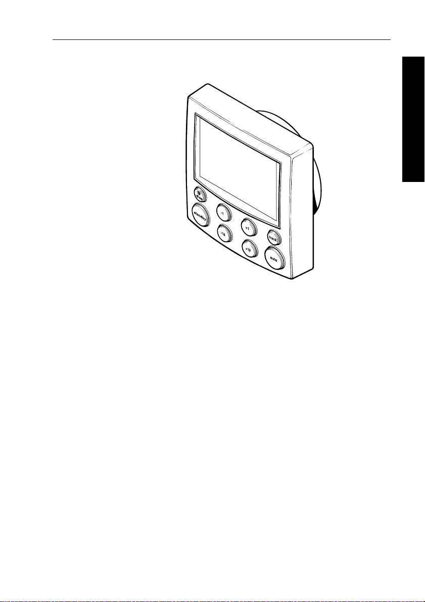
Control unit
How to install the surface mount and flush mount
control units, and connect power, SeaTalk and NMEA.
Fluxgate compass
How to install the fluxgate compass.
Tiller drive (tiller pilots only)
How to install the 4000 tiller drive.
Wheel drive (wheel pilots only)
How to install the wheel drive.
Rudder position sensor (wheel pilot option)
How to install the optional rudder position sensor for
wheel pilots.
5 Installing the ST4000+
page 44
page 48
page 55
page 59
page 70
page 81
Page 59

44 ST4000+ Wheel & Tiller Autopilots: Owner’s Handbook
5.1 Planning the installation
Before you start installing the autopilot system, read through the
relevant installation sections in this chapter .
After reading through the following EMC installation guidelines,
identify suitable locations for each part of the system:
• consider how you will run cables to and from each component
5 Installing the ST4000+
Tools required
• avoid running cables through bilges where possi ble
• avoid running cables close to fluorescent lights, engi nes, radio
transmitting equipment etc.
T o install this autopilot system you will need the following items:
• tape measure (metric/imperial)
• pliers and cross-head/pozi-drive screwdriver
• drill and drill bits:
• 5 mm (
• 3 mm (
• pencil, masking tape and center punch
• sandpaper/file to smooth cut edges
• for the control unit:
• jigsaw or 90 mm hole cutter (for the control unit aperture)
• SeaT alk cables (if required – see page 52)
• extra power cable (if required - see page 52)
• for the tiller drive only:
• two-part epoxy adhesive for tiller pin and mounting so cket
• installation accessories (if required – see page 61)
• drill bits as required
• appropriate power cable (see page 68) for the tiller socket
• for the wheel drive only:
• spanner for the wheel nut
• washing-up liquid (to lubricate the sp okes)
• hacksaw to cut the pedestal bracket
• 4 mm + 6 mm drill bits and 3 mm allen key (supplie d)
5
/32 in) for surface mount control unit
1
/8 in) for compass and rudder position sens or
Parts supplied
Use the following illustrations to check the parts supplied with your
ST4000+ autopilot system.
Page 60

Chapter 5: Installing the ST4000+ 45
Control unit and compass (all systems)
Control unit
No8 x 3/4 in
screw (x4)
Fluxgate compass
with 8 m (26 ft) cable
Gasket
!
COMPASSAREA
Stud (x2)
Control unit
power cable
1 m (3 ft 3 in)
Compass
warning
label
Thumb screw (x2)
Spade
connector (x12)
Control unit terminal cover
(if desired, attach to rear of control unit
after connecting all cables)
M4 x
25 mm
screw
Sun cover
5 Installing the ST4000+
Also packed: Handbook, Quick Reference Card, Worldwide Distributor List
Tiller drive parts
Plug
Cable clip
and screw,
No 6 x 1/2 in
Optional: installation accessories if required
Mounting
socket (D002)
Tiller drive
Tiller
pin (D001)
Socket screw
No 4 x 3/4 in (x2)
D5438-1
Socket
D5437-1
Page 61

46 ST4000+ Wheel & Tiller Autopilots: Owner’s Handbook
Wheel drive parts
Wheel drive parts
Wheel drive
Wheel drive
Pedestal bracket
Pedestal bracket
Spoke clamp (x3)
Spoke clamp (x3)
16 mm spoke
16 mm spoke
clamp insert (x3)
clamp insert (x3)
Clamp screw,
Clamp screw,
M5 x 16 mm (x6)
M5 x 16 mm (x6)
12 mm spoke
12 mm spoke
clamp insert (x3)
clamp insert (x3)
Bracket screw,
Bracket screw,
No 10 x 3/4 in (x4)
No 10 x 3/4 in (x4)
5 Installing the ST4000+
4 mm
4mm
drill bit
drill bit
3 mm
3mm
allen key
allen key
Cable clip
Cable clip
and screw,
and screw,
No 6 x 1/2 in
No 6 x 1/2 in
Optional: Bulkhead/box pedestal fitting kit E15017 (if required)
Optional: Bulkhead/box pedestal fitting kit E15017 (if required)
6 mm
6mm
drill bit
drill bit
Power cable
Power cable
4.5 m (15 ft)
4.5 m (15 ft)
EMC installation guidelines
D5439-1
D5439-2
All Raymarine equipment and accessories are designed to the best
industry standards for use in the recreational marine environment.
Their design and manufacture conforms to the appropriate
Electromagnetic Compatibility (EMC) standards, but correct
installation is required to ensure that performance is not
compromised.
Although every effort has been taken to ensure that they will perform
under all conditions, it is important to understand w hat factors could
affect the operation of the product.
The guidelines given here describe the conditions for opti mum EMC
performance, but it is recognized that it may not be possible to meet
all of these conditions in all situations. T o ensure the best possible
conditions for EMC performance within the constraints imposed by
any location, always ensure the maximum separation possible
between different items of electrical equipment.
For optimum EMC perform ance, it is recommended that wherever
possible:
Page 62

Chapter 5: Installing the ST4000+ 47
• Raymarine equipment and cables connected to it are:
• At least 3 ft (1 m) from any equipment transmitting o r cables
carrying radio signals e.g. VHF radios, cables and antennas.
In the case of SSB radios, the distance should be increased to
7ft (2m).
• More than 7 ft (2 m) from the path of a radar beam. A radar
beam can normally be assumed to spread 20 degrees above
and below the radiating element.
• The equipment is supplied from a se parate battery from that used
for engine start. Voltage drops below 10 V , and starter motor
transients, can cause the equipment to reset. This will not damage
the equipment, but may cause the loss of some information and
may change the operating mode.
• Raymarine specified cables are used. Cutting and rejoining these
cables can compromise EMC performance and must be avoided
unless doing so is detailed in the installation manual.
• If a suppression ferrite is attached to a cable, this ferrite shou ld not
be removed. If the ferrite needs to be removed during installation
it must be reassembled in the same position.
EMC suppression ferrites
The following illustration shows t ypical cable suppression ferrites
used with Raymarine equipment. Always use the ferrites supplied by
Raymarine.
5 Installing the ST4000+
D3548-2
Connections to other equipment
If your Raymarine equipment is to be connected to other equipment
using a cable not supplied by Raymarine, a suppression ferrite MUST
always be attached to the cable near to the Raymarine unit.
Page 63

48 ST4000+ Wheel & Tiller Autopilots: Owner’s Handbook
5.2 Control unit
Control unit dimensions
5 Installing the ST4000+
90 mm (3.55 in)
115 mm (4.53 in)
Location
Locate the ST4000+ control unit so it is:
• within easy reach from the steering position
• viewable straight on, or with a maximum viewing angle of 30°
• protected from physical damage
• at least 230 mm (9 in) from any compass
• at least 1 m (3 ft) from any radio/radar receivers/transmitters
The selected location should also:
• be clean, smooth and flat
• be accessible from behind (so you can secure and run cables)
• have sufficient space to accommodate the rear of the control unit
• allow at least 6 mm (
CAUTION:
The ST4000+ front cover is waterproof when in stalled according
to the following instructions. However , the rear cover must be
protected from water in a ventilated and draine d area. Any water
or water vapor in this area could cause damage by coming into
contact with electrical connections or condensation by entering
the contr ol unit thr ough its br eathing ho le.
110 mm (4.33 in)
24 mm
(0.95 in)
and connectors
1
/4in) between adjacent control units and
instruments so you can fit their sun cover s
17 mm
(0.67 in)
D3242-2
Page 64

Chapter 5: Installing the ST4000+ 49
Mounting procedure
Control units are available in surface mount and flush mount styles.
Surface mount control units
T o fit a surface mount control unit:
1. Apply the surface mount template (supplied at the back of this
handbook) to the selected bulkhead.
2. Mark the centers of the two fixing holes and the cable boss.
3. Drill two 5 mm (
4. Use a 90 mm (3.55 in) diameter cutter to drill the hole for the
cable boss.
5. Peel the protective sheet from the self-adhesive gasket, then stick
the gasket into position on the rear of the control unit surround.
6. Screw the fixing studs into th e control unit.
7. Pass the cables (power , compass, SeaT alk etc.) through the
bulkhead and connect them to the appropriate terminals (as
described later in th is chapter ).
8. Assemble the control unit to the bulkhead.
9. Secure the control unit with the thumb nuts provi ded.
Hand-tighten the thumb nuts – do NOT use a wrench.
3
/16in) diameter holes for the fixing studs.
Fixing stud
Thumb nut
5 Installing the ST4000+
Cable boss
Self-adhesive
gasket
D3243-3
Page 65

50 ST4000+ Wheel & Tiller Autopilots: Owner’s Handbook
Flush mount control units
T o fit a flush mount control unit:
1. Ensure that the intended mounting location is between 3 mm
1
(
/8in) and 20 mm (3/4in) thick.
2. Apply the flush mount templa te (supplied at the back of this
handbook) to the selected location. Mark the aperture into which
the control unit will sit, then remove the template.
5 Installing the ST4000+
3. Use a jigsaw to cut out this aperture.
4. Peel the protective sheet from the self-adhesive gasket, then stick
the gasket into position on the rear of the control unit surro und.
5. Screw the two fixing studs into the threaded sockets on the rear of
the control unit.
6. Pass the cables (power, comp ass, SeaT alk, etc.) through the
bulkhead and connect them to the appropriate terminals (as
described later in this chapter).
7. Place the assembled control unit, studs and gasket into the panel.
8. Locate the bracket onto the fixing studs and secure t he assembly
to the panel with the thumb-nuts. Hand-tighten the thumb nuts –
do NOT use a wrench.
Aperture
cut-out
Self-adhesive
gasket
Fixing
stud
Thumb
screw
Bracket
D4585-2
Page 66

Chapter 5: Installing the ST4000+ 51
Cable connectors
With the exception of the SeaT alk cables, spade connectors are used
to make al l connecti ons to the c ontrol un it.
When fitting the spade connectors, make sure the connector fits
securely over the blade and not between the connector and its plastic
insulating cover. Incorrect fitting will give intermittent contact which
will lead to faulty autopilot operation.
Power supply connection
• The autopilot requires its own dedicated power supply – it cannot
source its power from SeaT alk. However , it can be used to supply
power to other SeaT alk instruments.
• Y ou must fit a12 A fuse (or equivalent circuit breaker) to the
+12 V supply.
5 Installing the ST4000+
D3286-2
Brown (+) Blue (-)
Power
cable
(or equivalent
circuit breaker)
Blue (-)
Brown (+)
12 A fuse
+12 V
power
supply
D3287-2
Page 67

52 ST4000+ Wheel & Tiller Autopilots: Owner’s Handbook
5 Installing the ST4000+
• As standard, we supply a 1 m (3 ft 3 in) power cable terminated
1
with
/4inch spade connectors.
• Y ou can extend the power cable if required. Th e following table
shows the minimum acceptable cable sizes:
Cable length Copper area AWG
Up to 2.5 m (8 ft) 1.0 mm
Up to 4.0m (13ft) 1.5mm
Up to 6.0 m (19.5 ft) 2.5 mm
Note: If you need to extend the cable, you MUST use the correct cable
size.A lighter gauge cable might cause a voltage drop between the
supply and the control unit. This will reduce the power t o the drive,
causing slower response to course chan ges and corrections.
SeaTalk connections
Y ou will not need any SeaT alk cables to install the standard ST4000+
autopilot system.
However, if you want to connect your ST4000+ control unit to other
SeaT alk equipment, you will need to purchase the necessary cables
from your Raymarine dealer.
The following illustration shows the range of available SeaTalk
cables.
Flat moulded plugs at each end
2
2
2
18
16
14
Part no. Type Length
D284 Flat moulded plugs at each end 1 m (3 ft 3 in)
D285 Flat moulded plugs at each end 3 m (9 ft 10 in)
D286 Flat moulded plugs at each end 5 m (16 ft 5 in)
D287 Flat moulded plugs at each end 9 m (29 ft 6 in)
D288 Flat moulded plugs at each end 20 m (65 ft 6 in)
Flat moulded plug to round plug
Part no. Type Length
D187 Flat moulded plug to male round plug 0.15 m (6 in)
D188 Flat moulded plug to female round plug 0.3 m (12 in)
D5417-1
Page 68

Chapter 5: Installing the ST4000+ 53
Typical SeaTalk connections
NMEA connections
ST4000+ can receive wind and navigation data in NMEA 0183
format for use in Track and W ind Vane modes.
Receiving NMEA data
NMEA cabling
Connect the NMEA navigator or wind instrument to the NMEA IN
terminals on the rear of the ST4000+ control unit.
SeaTalk bus
Power supply
Autopilot control
unit (rear)
5 Installing the ST4000+
D3392-2
Navigator or
wind instrument
with NMEA output
Data
out (-ve)
Data
out (+ve)
Red
(data in +ve)
Control unit
(rear)
Blue
(data in -ve)
D3374-2
Page 69

54 ST4000+ Wheel & Tiller Autopilots: Owner’s Handbook
Note: If you need to connect more than one item of NMEA equipment,
you will need to connect one of them to the SeaTalk system using a
SeaTalk/NMEA Interface (part number: E85001).
NMEA data formats
TheST4000+ can decode the following NMEA 0183 navigation and
wind data:
Information NMEA 0183 data
5 Installing the ST4000+
Course Over Ground VTG, RMC, RMA
Speed Over Ground VTG, RMC, RMA
Cross Track Error APB, APA, RMB, XTE
Bearing to Waypoint APB, BWR, BWC, RMB
Distance to Waypoint BWR, BWC, RMB
Waypoint Number APB, APA, BWR, BWC, RMB
Apparent Wind Speed VWR, MWV
Apparent Wind Angle VWR, MWV
Speed Through Water VHW
Depth DBT
Water Temperature MTW
Note: The autopilot only decodes the last four characters of waypoint names.
This means that the last four characters of long waypoint names must be
unique for the waypoint advance function to work.
Transmitting NMEA data
Transmitting NMEA data on SeaTalk
If the ST4000+ receives any of the NMEA data shown above, and the
equivalent data is not present on SeaT alk, it will transmit the data onto
SeaTalk to make it available to other SeaT alk instruments:
• the ST4000+ transmits depth information in th e units defined by
the first page in the data page rollover
• the ST4000+ always transmits water temperature in °C
Transmitting NMEA data to NMEA equipment
If you want to transmit information to NMEA equipment, you wi ll
need to connect a SeaTalk /NMEA Interface (part number: E85001)
to the SeaT alk bus to convert SeaT alk data to NMEA data.
Page 70

Chapter 5: Installing the ST4000+ 55
5.3 Fluxgate compass
Location
The compass contains a self-levelling mechanism. This enables the
compass to provide accurate readings with pitch and roll movements
up to +/- 35°.
Note: The rattle that the fluxgate compass makes when shaken is
normal. It is caused by the pendulum weight hitting the inside of
the case.
Fluxgate compass dimensions
Standard location
The compass is primarily designed for below deck, bulkhead
mounting. On steel-hulled boats you must mount it above deck.
5 Installing the ST4000+
76 mm (3 in)
76 mm (3 in)
D5381-1
T o achieve the best performance from the compass, mount it:
• as near as possible to the boat’s pitch and roll center to minimize
compass disturbance
• at least 0.8 m (2 ft 6 in) away from the boat’s steering compass to
prevent deviation of either compass
• away from the front third of the boat (otherwise shock motion will
affect compass performance)
• away from potential sources of magnetic interference, such as:
motors, drive units, loudspeakers, alternators/starters, electric
cables, large ferrous objects (such as the engine, ballast, keel, gas
bottles and tool boxes)
Note: Becaus e you align the compass after installation (see
page 95),you can mount it so it faces in any directi on.
Page 71

56 ST4000+ Wheel & Tiller Autopilots: Owner’s Handbook
0.3L to 0.5L
5 Installing the ST4000+
L
D5401-1
Compass - recommended location for non-steel hulls
Finding the most suitable location
T o identify the best compass location on your boat, start at the pitch
and roll center then move the compass up and/or aft until you find a
location with minimal magnetic disturbance.
Note: T o check if the intended mounting location is free from
magnetic influence, tape a handheld compass to the chosen location,
then turn the boat through 360°. The r eadings on the handheld
compass and your boat’s main steering compass (if accurately
aligned) should not differ by more than10 ° at any heading.
Steel-hulled boats
On steel-hulled boats you must mount the compass at least 1.2 m (4 ft)
above the main deck or wheelhouse. Otherwise the compass will not
work correctly because the hull will prevent it from sensing the
Earth’s magnetic field. The following illustration shows
recommended mounting positions for steel-hulled bo ats.
Note: T he higher above the waterline you mount the compass, the
more the boat’s pitch and roll will aff ect compass performance.
Page 72

Chapter 5: Installing the ST4000+ 57
6 ft (1.8 m)
4 ft (1.2 m)
4 ft (1.2 m)
D5383-1
Compass - recommended location for steel-hulls
Mounting
5 Installing the ST4000+
Vertical
5384-1
D
Fluxgate compass - orientation
CAUTION:
Y ou mus t mount the fluxgate compass on a vertical bul khead,
with the cable exiting at the base.
1. Hold the compass against the mounting location.
2. Mark the four mounting holes, then remov e the compass.
3. Drill four pilot ho les using a 3 mm (
1
/8 in) drill bit.
Page 73

58 ST4000+ Wheel & Tiller Autopilots: Owner’s Handbook
4. Making sure the cable exits at the bottom of the compass, secure
the fluxgate compass using the self-tapping screws p rovided
(No 8 x
3
/4 in, pan-head).
Note: St ick the supplied warning label near to the co mpass, where it
is clearly visible.
Connecting to the control unit
5 Installing the ST4000+
1. The compass is supplied with 8 m (26 f t) of cable. Route the cable
to the control unit, taking into account the EMC installation
guidelines (page 46).
Note: Make sure you leave some spare cable so, if necessary, you can
re-position the compass to reduce deviation. If the standard cabl e is
not long enough, your Raymarine dealer can supply a 10 m (30 ft)
extension cable (part number: D174).
2. Connect the five cores of the cable as shown to the
Compass
terminals on the control unit.
Red
Screen
Blue Yellow Green
D3282-2
Page 74

Chapter 5: Installing the ST4000+ 59
5.4 Tiller drive (tiller pilots only)
Critical dimensions
Installing the tiller drive involv es mounting it between the tiller and a
fixed point on the boat’s structure. T wo dimensions are critical for
correct installation:
• Dimension A = 620 mm (24.5 in): the distance from the
mounting socket to the tiller pin. P ull out the drive pushrod to this
dimension.
Note: If your installation requi res a pushrod extension (see page61)
or cantilever mount (see page 65),this dimension will increase.
• Dimension B = 460 mm (18 in): the distance from the rudder
stock’s center line to the tiller pin.
468 mm (18.4 in)
'A'
620 mm (24.5 in)
38 mm
(1.5 in)
44 mm
(1.7 in)
5 Installing the ST4000+
'B'
460 mm
(18 in)
'B' 460 mm (18 in)
90˚
Rudder axis
Sloping rudderstock
D5339-1
Page 75

60 ST4000+ Wheel & Tiller Autopilots: Owner’s Handbook
1. Clamp the tiller on the boat’s center line and mark dimensions A
and B.Use masking tape to locate the fixing points for the tiller pin
and mounting socket.
Note: Y ou can measure dimension A on either the port or starboard
side of the cockpit, depending on which side you intend to mount the
drive. If you select port mounting, you must correct the autopilot
steering direction as described on page 86.
5 Installing the ST4000+
2. Make sure the measurements are at right angles (as shown on the
diagram).
3. Make sure that the drive unit is mounted horizontally.
Basic installation
After establishing the control dimensions A and B, y ou can usually
mount the tiller drive directly onto the cockpit seat.
12.5 mm
(0.5 in)
Mounting socket
Tiller pin
D284-2
Installing the tiller pin (part no. D001)
1. Drill a 6 mm (1/4in) diameter hole to a depth of 25 mm (1 in) at
the fixing point you have marked on the tiller .
2. Use a two part epoxy adhesive (e.g. Araldite) to fix the tiller pin in
place.
3. Position the shoulder of the pin so it is 12.5 mm (
tiller surface.
1
/2in) above the
Page 76

Chapter 5: Installing the ST4000+ 61
Installing the mounting socket (part no. D002)
1. Drill a 12.5 mm (1/2in) diameter hole to a depth of 25 mm (1 in) at
the fixing point you have marked on the cockpit seat.
2. If the structure at the mounting position is less than 25 mm (1 in)
thick, reinforce the underside with plywood b onded into position.
3. Install the mounting socket using a two part epoxy adhesive.
CAUTION:
As the tiller pilot is capable of generating high pushrod loads,
you MUST:
• drill holes to the specified size and reinforce where necessary
• allow the epoxy to harden completely be fore apply a load
Installation accessories
If you are not able to install the drive unit directly onto the cockpit seat
or tiller as described, use one (or a combination) of the following
accessories:
• pushrod extensions
• tiller brackets
• cantilever sockets
• pedestal sockets
5 Installing the ST4000+
Pushrod extensions
If you need to increase the pushrod length (because of the distance
from the mounting socket location to the center line), use a
Raymarine pushrod extension.
Identifying the correct pushrod extension
1. Clamp the tiller on the boat’s center line.
2. Measure dimension C.
3. Select the appropriate pushrod extension length (and part
number) using the following table.
Page 77

62 ST4000+ Wheel & Tiller Autopilots: Owner’s Handbook
Dimension C Pushrod extension length L Part no.
620 mm (24.5 in) Standard dimension -
648 mm (25.5 in) 25 mm (1 in) D003
673 mm (26.5 in) 51 mm (2 in) D004
699 mm (27.5 in) 76 mm (3 in) D005
724 mm (28.5 in) 102 mm (4 in) D006
5 Installing the ST4000+
749 mm (29.5 in) 107 mm (5 in) D007
775 mm (30.5 in) 152 mm (6 in) D008
C
L
Mounting the pushrod extension
T o mount the pushrod extension:
1. Unscrew the end of the tiller drive’s push rod.
2. Screw the extension into the pushrod.
3. Screw the pushrod end into the pushrod extension.
D285-2
Page 78

Chapter 5: Installing the ST4000+ 63
Tiller brackets
If the tiller is higher or lower than the mounting socket, you can use a
Raymarine tiller bracket to vary the tiller pin offset so the drive is
horizontal.
Identifying the correct tiller bracket
1. Clamp the tiller on the boat’s center line.
2. Measure dimension D (if the pushrod is above the tiller) or
dimension E (if the pushrod is below the tiller).
3. Select the appro priate br acket from the follow ing table:
Dimension D
(pushrod below tiller)
25 mm (1 in) 51 mm (2 in) D009
51 mm (2 in 76 mm (3 in) D010
76 mm (3 in) 102 mm (4 in) D011
102 mm (4 in) 127 mm (5 in) D159
127 mm (5 in) 152 mm (6 in) D160
Mounting the tiller bracket
1. Position the tiller bracket on the center line of the tiller (above or
below) and establish the critical dimensions A and B
Dimension E
(pushrod above tiller)
Bracket
part no.
5 Installing the ST4000+
Note: To measure dimension B on a boat with a sl oping rudderstock,
refer to the diagram on page65.
2. Mark the centers of the two bracket mounting holes.
3. Drill two 6 mm (
1
/4in) diameter holes through the center line of
the tiller at the positions you have marked.
4. Attach the tiller bracket using two 6 mm (
1
/4in) diameter bolts,
nuts and washers.
5. Bond the fixing bolts in place with two part epoxy adhesive
6. When the epoxy is completely hardened, fully tighten the nuts.
7. Attach the tiller pin to the bracket.
Page 79

64 ST4000+ Wheel & Tiller Autopilots: Owner’s Handbook
5 Installing the ST4000+
D
D286-2
E
D287-2
Page 80

Chapter 5: Installing the ST4000+ 65
'B'
90 degrees
D309-2
Cantilever mounting
If you need to attach the tiller drive to a vertical face (such as the
cockpit sidewall), use a Raymarine cantilever socket assembly
(part number D031):
• the maximum possible extension of fset is 254 mm (10 in)
• you cut the cantilever to the exact length during mounting
5 Installing the ST4000+
Cutting the cantilever rod to length
1. Clamp the tiller on the boat’s center line.
2. Measure dimension F (actual).
3. Refer to the table to establish a cutting length for the cantilever
rod – double check measurements before cutting.
4. Measure the rod from threaded end, then cut the cantilever rod
to length L using a hacksaw . Remove any sharp edges with a file.
Dimension F Cut length L
686 mm (27 in) 51 mm (2 in)
711 mm (28 in) 75 mm (3 in)
737 mm (29 in) 102 mm (4 in)
762 mm (30 in) 127 mm (5 in)
787 mm (31 in) 152 mm (6 in)
813 mm (32 in) 178 mm (7 in)
838 mm (33 in) 203 mm (8 in)
Page 81

66 ST4000+ Wheel & Tiller Autopilots: Owner’s Handbook
F
5 Installing the ST4000+
L
Mounting the cantilever assembly
T o mount the cantilever assembly:
1. Temporarily assemble the cantilever by screwing the rod into the
mounting ring.
2. Ensure the drive unit is horizontal and then mark the location of
the mounting ring and its mounting holes.
3. Drill three 6 mm (
1
/4in) diameter holes at the positions you have
marked.
4. Bed the mounting ring on a thin coat of silicon sealant.
1
5. Use three 6 mm (
/4in) diameter bolts, nuts and washers to attach
the mounting ring to the backing plate (with the backing plate on
the other side of the mounting surface, as shown above).
6. Screw the rod firmly into place.
7. Roughen the end of the cantilever rod and the inside of the cap to
provide a key . Then apply two part epoxy adhesi ve to the rod end
and the cap.
8. Place the cap over the rod end, making sure the hole for the
drive unit mounting pin faces upwards. Allow the epoxy
adhesive to harden fully before applying a load.
Note: When the autopilot is not in use, you can unscrew the complete
rod assembly to leave the cockpit unobstructed.
D288-2
Page 82

Chapter 5: Installing the ST4000+ 67
Pedestal socket mounting
If you need to raise the height of the drive unit mounting socket t o
keep the tiller drive horizontal, use a Raymarine pedestal socket
assembly .
Identifying the correct pedestal socket
L
G
D289-2
1. Clamp the tiller on the boat’s center line.
2. Establish the standard control dimensions A and B.
3. With the tiller drive horizontal, measure dimension G.
4. Select the appropriate pedestal socket assembly from the table.
Dimension G Pedestal socket length L Part no.
38 mm (1.5 in) Standard dimension -
76 mm (3.0 in) 38 mm (1.5 in) D026
89 mm (3.5 in) 50 mm (2.0 in) D027
102 mm (4.0 in) 64 mm (2.5 in) D028
114 mm (4.5 in) 76 mm (3.0 in) D029
127 mm (5.0 in) 89 mm (3.5 in) D030
5 Installing the ST4000+
Mounting the pedestal socket
1. Mark the mounting ring’s position on the cockpit seat or count er.
2. Ensure that control dimensions A and B are correct.
3. Mark the bolt holes on the mounting ring and then drill three
1
6 mm (
/4in) diameter holes.
Page 83

68 ST4000+ Wheel & Tiller Autopilots: Owner’s Handbook
5 Installing the ST4000+
4. Bed the mounting ring on a thin coat of silicon sealant.
5. Use three 6 mm (
1
/4in) diameter bolts, nuts and washers to attach
the mounting ring to the backing plate (with the backing plate on
the other side of the mounting surface, as shown above).
6. Screw the mounting socket firmly into place.
Note: When the autopilot is not in use, you can unscrew the complete
rod assembly to leave the cockpit unobstructed.
Tiller pins
Y our Raymarine dealer can also supply the following lengths of tiller
pin for other non-standard installation s.
Description Size Part no.
Small threaded tiller pin 25 mm (1.0 in) D014
Extra length tiller pin 72 mm (2.8 in) D020
Extra length threaded tiller pin 72 mm (2.8 in) D021
Connecting to the control unit
• Connect the tiller drive to the control unit via the waterproof plug
and socket (supplied).
• The plug comes ready assembled to the tiller drive.
• Mount the socket in the cockpit next to the tiller drive.
Cabling
1. Measure the total length of cable run from the control unit to the
socket location.
Use this table to identify the appropriate power cable size:
Cable length Copper area AWG
Up to 2.5 m (8 ft) 1.0 mm
Up to 4.0m (13ft) 1.5mm
Up to 6.0m (22ft) 2.5mm
2
2
2
2. Route the cable from the control unit to the socket location.
3. Use a suitable tool to crimp the spade receptacles (supplied) to the
two cores.
4. Connect them as shown to the
Drive terminals on the control unit.
18
16
14
Page 84

Chapter 5: Installing the ST4000+ 69
5 Installing the ST4000+
Brown Blue
D3284-2
Installing the socket
1. Apply the template (supplied at the rear of this handbook) to the
bulkhead.
2. Carefully drill a 18 mm (
3
(
/32in) pilot holes. Remove the template.
3. Pass the cable through the bulkhead and attach to the socket,
making sure you connect each core to the correct pin (as shown).
Rear of socket
Drive (blue)
3 stripe terminal
To the
control unit
4. Attach the socket to the bulkhead using the two self-tapping
screws. Use cable clamps to secure the drive cable at regular
intervals.
23
/32in) clearance hole and two 2.5 mm
Terminal
identification
stripes
Drive (brown)
2 stripe terminal
D383-5
Page 85

70 ST4000+ Wheel & Tiller Autopilots: Owner’s Handbook
5.5 Wheel drive (wheel pilots only)
The Raymarine wheel drive will fit 3, 4, 5, 6, 7 or 8 spoke wheels. It is
designed to operate with steering systems with between 1 to 3.5 turns
lock to lock.
Note: In the following cases , you must fit a rudder position sens or to
your wheel drive system (see page 81):
5 Installing the ST4000+
• If your steering system has significant l ost motion that you cannot
correct. (Any play in your boat’s steering will degrade autopilot
performance, so always try to minimize this lost motion.)
• If you are installing the wheel drive on a hydrauli c steering system.
Clamp screw,
M5 x 16 mm (x6)
Wheel drive
front cover
Pre-drilled spoke
clamp holes (x2)
Bracket screw,
No 10 x 3/4 inch (x4)
Pedestal
bracket
Bracket pin
Spoke clamp (x3) Clamp insert (x3)
Wheel drive – main parts (see page 114 for dimensions)
Installation stages
Installing the wheel drive involves four stages:
1. Drilling the spoke clamp holes in the front cover.
2. Securing the wheel drive to the wheel.
3. Attaching the pedestal bracket.
4. Connecting the drive to the control unit.
Cable plug
Cable socket
Motor tube
Clutch lever
D5402-2
Page 86

Chapter 5: Installing the ST4000+ 71
Drilling the spoke clamp holes
1. Remove the wheel drive front cover:
• the front cover is held onto the wheel drive by three ‘push-fit’
posts which sit in three sockets on the drive ring
• to remove the cover, hol d the motor in one hand and use your
other hand to pull the cover up and away from the drive unit
(as shown below)
2. Identify the appropriate spoke clamp holes for your wheel. With
the arrow at the top, refer to the following diagrams:
• the holes are numbered inside the cover (e.g. if you have a 5
spoke wheel, you need to drill the 4 locations marked with ‘
• mark the appropriate spoke clamp holes and check them by
holding the cover against your wheel
5 spokes 7 spokes
Top 2 spoke clamp holes
are pre-drilled
5 Installing the ST4000+
D5403-1
5’)
D5348-1a
Page 87

72 ST4000+ Wheel & Tiller Autopilots: Owner’s Handbook
3 or 6 spokes 4 or 8 spokes
Top 2 spoke clamp holes
are pre-drilled
5 Installing the ST4000+
Note: T he wheel drive is designed to work with 3 spoke clamps o n
4 or 8 spoke wheels. For cosmetic reasons, however, you may want to
fit an extra spoke clamp to the fourth spoke. Raymarine dealers can
supply an extra spoke clamp (part number A18089).
D5348-1b
3. Drill the appropriate spoke clamp holes using the larger of the
supplied drill bits (6.0 mm or
1
/4in):
• drill from the inside, placing a piece of scrap wood under the
cover to produce a clean exit hole
• you will need to drill 4 new holes so the cover has 6 hol es in
total (2 for each spoke clamp)
Note: The spoke clamps will cover these exit holes, so they will not be
visible when the wheel drive is installed.
Piece of scrap wood
D5347-1
Page 88

Chapter 5: Installing the ST4000+ 73
4. Align the cover with the wheel drive:
• the two pre-drilled holes (marked with an arrow) must line up
with their matching pair of threaded inserts on the drive ring
(also marked with an arrow)
• make sure that the other spoke clamp holes align with their
threaded inserts
Note: The cover will only fit back onto the wheel drive when you have
aligned the two parts correctly.
Pre-drilled holes
(marked with arrow)
Pair of threaded inserts
(marked with arrow)
5 Installing the ST4000+
Front cover Drive unit
5. Fit the cover back onto the wheel drive:
• press the cover in the three places shown on the diagram
below to push each of the posts back into its locating socket
Note: T his step is easier with the clutch engag ed.
TOP
Drive ring
D5404-1
D5405-1
Page 89

74 ST4000+ Wheel & Tiller Autopilots: Owner’s Handbook
Securing the wheel drive to the wheel
1. Remove the wheel from the pedestal and place it on top of the
drive unit, with the front of the wheel and drive both facing up.
2. Using the wheel drive template at the end of this book, select the
correct set of spoke clamp inserts for your wheel:
• measure the spoke diameter at a distance of about 135 mm
(5.3 in) from the center of the wheel
5 Installing the ST4000+
• select the appropriate set of inserts: the wheel drive is supplied
with 2 sets of 3 inserts suitable for 12 mm (
5
(
/8 in) diameter spokes – each insert is marked with its size
1
/2 in) and 16 mm
3. Fit the first spoke clamp:
• lubricate the spoke with washing-up liquid – so you can sl ide
the spoke clamp along the spoke to adjust its posit ion
• place the insert on the spoke about 135 mm (5.3 in) from the
wheel center – this distance is not critical as the wheel drive
will self-center as you fit all 3 spoke clamps
• place the spoke clamp onto the insert, making sure that you
have correctly located the clamp insert in the clamp
• locate 2 of the clamp screws (M5 x 16 mm allen-head screws)
• lightly tighten the screws using the 3 mm allen key (supplied)
135 mm (5.3 in)
D5406-1
4. Repeat step 3 to fit the other 2 spoke clamps. As you fit each one,
adjust the position of the wheel relative to the wheel drive so the
holes in t he clamp li ne up with the holes in the cov er . As you do
this, the wheel drive will self-center on the wheel.
5. After fitting all 3 spoke clamps, fully tighten the screws.
Page 90

Chapter 5: Installing the ST4000+ 75
Attaching the pedestal bracket
Note: If your wheel is bulkhead or box pedestal mounted, you will
need to obtain a bulkhead f itting kit (part number E15017) f rom your
Raymarine dealer. Fitting instructions are supplied with the kit.
Motor tube location
Depending on the design of your pedestal and any surroun ding
obstructions, you can mount the wheel drive in one of tw o ways:
• Slot 1 installation: the standard po sition uses slot 1 on the back of
the wheel drive (the slot closest to the motor tube) so the motor
tube is at the bottom to the right of the pedestal
• Slot 2 installation: the alternative installation uses slot 2 to
position the motor tube at the top to the left of the pedestal
Select the appropriate slot so the motor tube is clear of obstructions.
CAUTION:
If you use slot 2 and you have a p edestal-mounted compass, the
drive motor may affect compass r eadings.
Slot 1 installation:
motor tube at
bottom right
Slot 2 installation:
motor tube at
top left
5 Installing the ST4000+
Slot 1
Slot 2
D5407-2
Page 91

76 ST4000+ Wheel & Tiller Autopilots: Owner’s Handbook
Pedestal bracket – length and position
Note: If you are replacing an existing 4000 wheel drive, you need to:
remove the old pedestal bracket, cut the new bracket pin to the
correct length (see steps 2 and 3 below), then secure it in the standard
orientation using the existing pedes tal holes.
1. Fit the wheel onto the pedestal, tighten the wheel nut to hold the
wheel in place, and engage the wheel drive’s clut ch:
5 Installing the ST4000+
• if possible, lock the wheel in position with the appropriate slot
centered at the bottom of the wheel
• otherwise, you will find it useful to have an assistant t o hold
the wheel in position so you can locate the bracket correctly
2. Measure dimension A – the distance between the front of the
pedestal and the rear edge of the drive’s front cover (see diagram):
• you may find it easiest to hold the bracket below the wheel
drive and mark dimension A directly on the pin
Cut here
A
A
10 mm
Note: If the wheel is bent or not running true, dimension A will
change with the wheel position. Measure the smallest distance.
3. Use a hacksaw to cut the pin 10 mm (0.4 in) LONGER than
dimension A. Remove any sharp edges at the cut end with
sandpaper or a file.
4. Place the pin end in slot 1 or 2 (as required):
• to do this you may need to loosen the wheel nut so you can
slide the wheel forward slightly, place the pin end in the slot,
return the wheel to its normal position and re-tighten the
wheel nut
D5343-2
Page 92

Chapter 5: Installing the ST4000+ 77
Note: Y ou can install the pedestal bracket either way up. In the
standard orientation the pin is at the bottom (below the mounting
holes – see diagram). If obstructions on the pedestal prevent you
from using the standard orientation, you can install the bracket so the
pin is at the top (above the mounting holes).
Standard
(also for retro-fit)
Alternative
D5408-3
5. Making sure the slot is central at the bottom of the drive unit
(6 o’clock position) and the pin is in the middle of the slot,
carefully draw around the bracket.
5 Installing the ST4000+
D5345-2
6. Remove the wheel, then hold the bracket on the pedestal in the
location you have marked.
7. Check the position and alignment of the pedestal bracket:
• the bracket pin should be 154 mm (6.1 in) below the pedestal
spindle (see the following diagram)
• the bracket pin should be aligned so it is directly below the
pedestal spindle (see the following diagram)
Page 93

78 ST4000+ Wheel & Tiller Autopilots: Owner’s Handbook
5 Installing the ST4000+
154 mm
(6.1 in)
D5346-2
8. When the pedestal bracket is correctly positioned and aligned,
mark around the inside of the slots, then remove the bracket.
9. Use a center-punch to mark the center of each slot, then use the
smaller supplied drill bit to drill a 4.0 mm (
5
/32in) diameter hole.
Note: Dri ll at right angles to the pedestal surface.
D5344-2
10. Hold the bracket in place then lightly tighten the four cross-head
screws (No 10 x
3
/4 in). As you do this, make sure the bracket is
correctly aligned.
11. Replace the wheel, making sure that you locate the pin in the
correct slot (slot 1 or slot 2).
12. Turn the wheel with the clutch off to check that the bracket is
correctly positioned and aligned.
Page 94

Chapter 5: Installing the ST4000+ 79
Note: If the wheel is bent or the wheel drive is off center, the pin will
move up and down in the back plate slot. As long as the pin do es not
hit the top or bottom of the slot, this pin movement will not affect the
drive unit’s performance.
13. When you have checked alignment, fully tighten all four screws.
Connecting to the control unit
When you have attached the pedestal bracket, you need to connect the
wheel drive to the control unit. The drive unit is supplied with 4.5 m
(15 ft) of 2-core cable with a waterproof socket at one end.
1. Connect the socket to the plug on the wheel drive’s motor tube:
• remove the socket cover
• pull back the plug cover
• align the locking ring, plug and socket as shown below
Socket
Contact
5 Installing the ST4000+
Locking ring
Socket coverMotor tube
Plug
(pulled back)
CablePlug cover
D5409-1
• push the plug firmly into the socket
• turn the locking ring 90° clockwise
• make the connection waterproof by pulling the plug cover
across so it protects the plug and socket
Note: T o remove the plug, pull back the cover and turn the locking
ring 90° anti-clockwise. If you disconnect the socket for any reason,
always use the attached rubber cover to protect the socket.
Page 95

80 ST4000+ Wheel & Tiller Autopilots: Owner’s Handbook
2. Route the cable through the pedestal (or guard rail) and back to the
control unit:
• if the pedestal has a cable duct, use this for the drive cable to
make sure that it cannot foul the steering mechanism
5 Installing the ST4000+
D5338-1
3. Run the drive cable back to the control unit and connect the two
cores to the
Drive terminal s as shown.
Brown Blue
D3284-2
Page 96

Chapter 5: Installing the ST4000+ 81
5.6 Rudder position sensor (wheel pilot option)
If you connect the optional Raymarine rudder posi tion sensor (part
number: M81105) to your w heel drive system, the autopilot will use
the accurate rudder position information to improve performance.
The ST4000+ will also use this information to show the true rudder
angle in Standby and Auto modes.
Note: Y ou must fit a rudder position sensor to your wheel drive
system if there is significant lost motion in your steering system or if
you are installing the wheel drive on a hydraulic steering s ystem.
The rudder position sensor connects d irectly to the boat’s tiller arm or
quadrant. Installing the sensor involves five main steps:
• ensuring correct alignment
• securing the sensor to the boat
• attaching the sensor to the tiller arm
• checking alignment
• connecting to the control unit
187 mm (7.35 in)
140 mm (5.5 in)
60 mm (2.4 in)
5 Installing the ST4000+
Ensuring correct alignment
CAUTION:
T ake care to ensure correct rudder sensor alignment. If the
sensor is not correctly aligned, the autopilot system will not
perform accurately.
Vertical alignment
When viewed from the front (as shown in the illustration below), the
connecting rod should be as level as possible, so the ball-joints at each
end are level. It should also remain parallel to the tiller arm’s plane of
rotation at all times.
Note: If misalignment exceeds +/-5° the ball-joints will bind or fail.
70 mm (2.75 in)
D5386-1
Page 97

82 ST4000+ Wheel & Tiller Autopilots: Owner’s Handbook
Front view - rudder amidships
Ball joints (level)
Parallel
Tiller arm
or quadrant
Connecting rod
Sensor arm
Rudder position
sensor
Mounting base
5 Installing the ST4000+
Top view - rudder amidships
Aft
Min: 101 mm (4 in)
Optimum: 140 mm (5.5 in)
Max: 190 mm (7.5 in)
Parallel
90˚
Cable entry
60˚ 60˚
Maximum
permitted
travel: +/- 60˚
Minimum: 75 mm (3 in)
Maximum: 310 mm (12 in)
D5387-1
Horizontal alignment
When viewed from above (as shown in the illustration above):
• the sensor arm must be between 75 mm (3 in) and 310 mm (12 in)
from the tiller arm
• with the rudder amidships, the sensor arm should be at 90° to t he
connecting rod and directly opposite the cable entry point o n the
sensor body
• when the rudder moves from hardover to hardover:
• the sensor arm and the tiller arm must remain parallel to each
other at all times
• sensor arm movement must not exceed +/- 60°: if the steering
system drives the sensor arm beyond these limits it wi ll
damage the rudder position sensor
Page 98

Chapter 5: Installing the ST4000+ 83
Securing the sensor to the boat
Location
Mount the rudder position sensor on a suitable base alongsi de the
rudder stock and tiller arm.
Note: If necessary, you can install the sensor upside down. If you
mount the sensor in this way, you must swap the red a nd green cable
connections at the control unit.
Securing the rudder position sensor
1. Hold the sensor in place, mark the mounting holes, then remove
the sensor (if required, use the template supplied).
2. Drill the pilot holes using a 3 mm (
3. Attach the sensor to the mounting base using the three
self-tapping screws supplied (pan-head No 8 x
Note: To make minor adjustments to the sensor alignment, loosen the
screws, rotate the sensor body, then re-tighten the screws.
1
/8 in) drill bit.
Attaching the sensor to the tiller arm
Attaching the tiller pin to the tiller arm
1. For optimum performance, mount the tiller pin on the tiller arm
140 mm (5.5 in) from the rudder stock center line.
3
/4 inch).
5 Installing the ST4000+
Note: If necessary, you can fit the tiller pin anywhere between
101 mm (4 in) and 190 mm (7.5 in) from the rudder stock. This wi ll
not affect autopilot performance, but will sl ightly alter the scaling of
the rudder angle display shown on the control unit.
2. Hold the tiller pin in place (either along or across the tiller arm),
mark the mounting holes then remove the tiller pin.
3. Drill pilot holes using a 3 mm (
1
/8 in) drill bit.
4. Attach the tiller pin to the tiller arm using the two self-tapping
screws supplied (countersunk No 8 x
3
/4 inch) or suitable bolts,
nuts and lock washers.
Page 99

84 ST4000+ Wheel & Tiller Autopilots: Owner’s Handbook
Attaching the connector rod
1. Use a hacksaw to cut the threaded connector rod to length.
2. Screw the lock nuts onto the road and then the ball-pin sockets.
3. Press the sockets onto the pins on the sensor arm and tiller pin.
Note: T o give the precise rudder position, the rudder sensor has a
built-in spring to remove any free play in the linkage to the tiller.
5 Installing the ST4000+
Checking alignment
Move the rudder from hardover to hardover and check that at all
rudder angles:
• all moving parts of the sensor remain free from any obstructio ns
• the sensor and connecting rod remain accurately aligned
• the ball joints do not bind
Connecting to the control unit
1. The rudder position sensor is supplied with 10 m (32 ft) of cable.
Route the cable to the control unit, taking into account the EMC
installation guidelines (page 46).
2. Connect the four cores of the cable (color for color) to the
terminals on the control unit as shown.
Note: If the standard cable is not long enough, your Raymarine
dealer can supply a 10 m (30 ft) extension cable (part number: D173).
Blue
Red
Rudder
Green
Screen
D3283-3
Page 100

Chapter 6: Setting-up the ST4000+ 85
Chapter 6: Setting-up the ST4000+
When you have installed the system, you need to check that the
system is wired correctly and set up to suit your type of boat.
The secti ons in this chapter p rovide in struction s for the fol lowing
post-installation procedures:
Functional test
6.1
6.2
6.3
6.4
This consists of a few basic tests to confirm that you
have connected the system correctly.
Check rudder sensor operation (if fitted)
This is necessary if you have fitted an optional rudder
position sensor (wheel drives only).
Initial sea trial
The purpose of the initial sea trial is to swing the
compass (and align the heading), and check autopilot
operation and rudder gain.
Autopilot calibration techniques
This explains how to optimize the autopilot set-up for
your boat.
page 86
page 90
page 91
page 98
6 Setting-up the ST4000+
Note: Y ou can perform further customizati on after the sea trial, as
described in Chapter 7: Cust omizing the ST4000+.
 Loading...