

Page 1
SR50/SR100 Sirius Weather Systems
Installation Guide
Document Number: 87069_1
Date: December 2006
Page 2
Trademarks and registered trademarks
Autohelm, HSB, Raymarine, RayTech, RayTech RNS, Sail Pilot, SeaTalk and
Sportpilot are registered trademarks of Raymarine Limited. Apelco is a
registered trademark of Raymarine Holdings Limited (Registered in all
major marketing territories).
AST, Autoadapt, Auto GST, Autoseastate, Autotrim, Bidata, Marine Intelli
gence, Maxiview, On Board, Raychart, Raynav, Raypilot, Raystar, ST40,
ST60, Seaclutter, Smart Route, Tridata and Waypoint Navigation are trade
marks of Raymarine Limited.
NOWRad is a registered trademark of Weather Service International (WSI)
All other product names mentioned are trademarks or registered trade
marks (if applicable) of their respective companies.
© Raymarine Inc. 2006
Page 3
i
Important information ......................................................... 1
Introduction........................................................................................... 1
Disclaimer ............................................................................................. 1
EMC conformance................................................................................. 1
Warranty ............................................................................................... 1
Handbook information ..........................................................................2
Safety notices ........................................................................ 3
Installation ............................................................................. 5
What’s in the box? ................................................................................6
What tools do I need.............................................................................6
Cable runs .............................................................................................8
Installing the system .............................................................................9
System connections ............................................................ 14
System activation................................................................................18
Upgrading weather receiver software ............................ 19
Maintenance and troubleshooting ................................... 20
Introduction......................................................................................... 20
Maintenance .......................................................................................20
Troubleshooting..................................................................................20
Accessories.......................................................................................... 21
Glossary of weather terms ................................................ 23
Using the Weather application ......................................... 27
Introduction.........................................................................................27
Overview .............................................................................................27
Setting up the application ...................................................................27
The weather display ............................................................................29
Weather options..................................................................................30
Animating weather graphics ...............................................................36
Troubleshooting the weather application............................................40
Page 4
1 Raymarine Sirius Weather System Installation Guide
Important information
Introduction
D9060_1
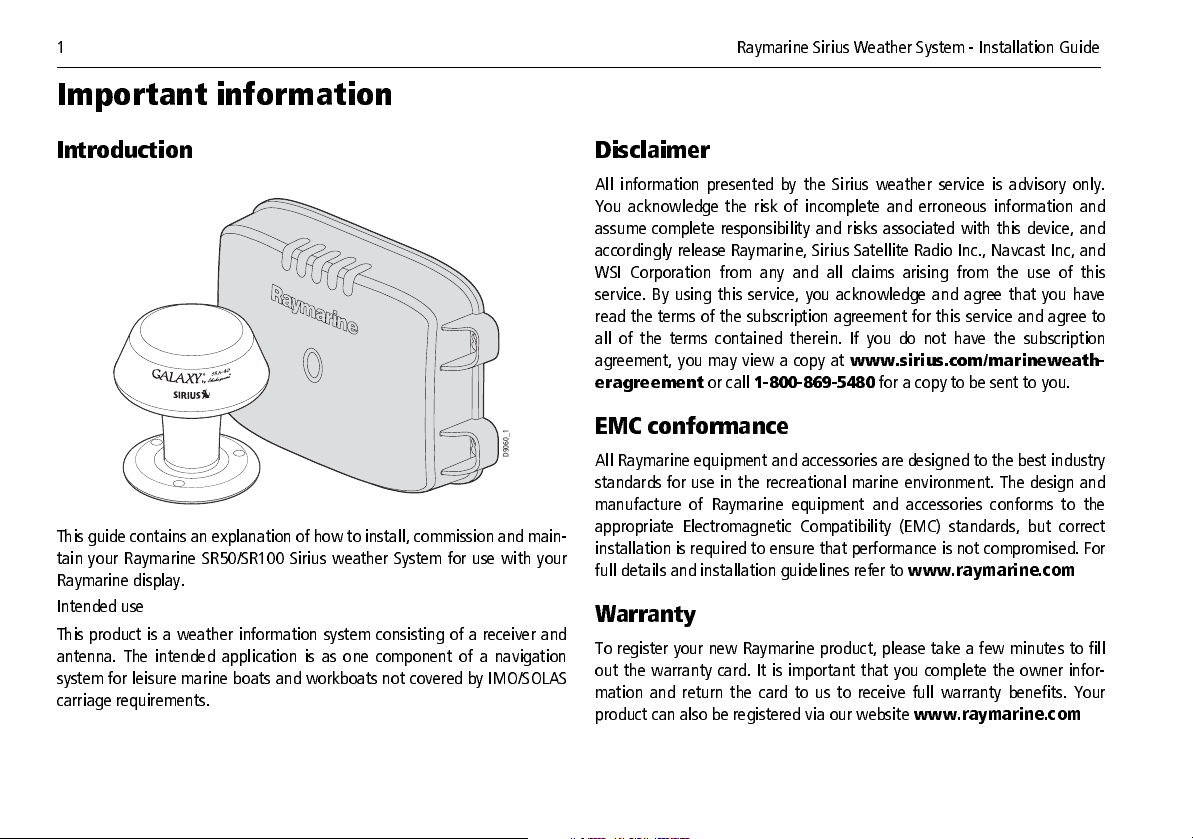
This guide contains an explanation of how to install, commission and main
tain your Raymarine SR50/SR100 Sirius w eather Syste m for use with your
Raymarine display.
Intended use
This product i s a we ather information system c onsisting of a rece iver a nd
antenna. The intended application is as one component of a na vigation
system for leisure marine boats and w orkboa ts not cove red by IMO/S OLAS
carriage requirements.
Disclaimer
All informa tion presented by the Si rius weather service is advisory only.
You acknow ledge the risk of incomple te and erroneous information and
assume complete responsibility and risks assoc iated with this devi ce, and
accordingly re le ase Ray marin e, S iri us S ate lli te Radi o Inc ., Navc ast Inc, and
WSI Corporation from any and all claims arising from the use of this
service. By using this ser vice, you acknowle dge and agree that you have
read the te rms of the subsc ripti on a gree me nt f or thi s se rvic e and agre e to
all of the terms contained therein. If you do not have the subscription
agreement, you may vi ew a copy at
eragreement
or call
18008695480
www.sirius.com /marineweath
for a copy to be sent to you.
EMC conformance
All Raymarine equipment and accessories are designed to the best industry
standards for use i n the rec reation al marine environme nt. The design and
manufacture of Raymarine equipment and accessories conforms to the
appropriate Electromagnetic Compatibility (EMC) standards, but correct
installation is required to ensure that performance is not compromised. For
full details and installation guidelines refer to
www.raymarine.com
Warranty
To register your new Ray marine produc t, please ta ke a f ew minute s to fill
out the warranty ca rd. It is important that you complete the ow ner infor
mation and return the card to us to rece ive full warranty bene fits. Your
product can also be registered via our website www.raymarine.com
Page 5
Important information 2
Handbook information
To the best of our k nowl edge , the inf ormati on cont aine d in th is handbook
was correc t as it went to press. Rayma rine cannot ac cept any liabi lity for
any inaccuracies or omissions it may contain.
In addition, our policy of continuous product improvement may change
specifications without notice. As a result, Raymarine cannot accept liability
for any differences between the product and the handbook.
Handbook conventions
Throughout this handbook, the dedicated (labelled) keys are shown in bold
capitals, e.g.
ALL.
MENU
. The soft key functions are shown in italics, e.g.
SAVE
Page 6
3 Raymarine Sirius Weather System Installation Guide
Safety notices
WARNING
WARNING
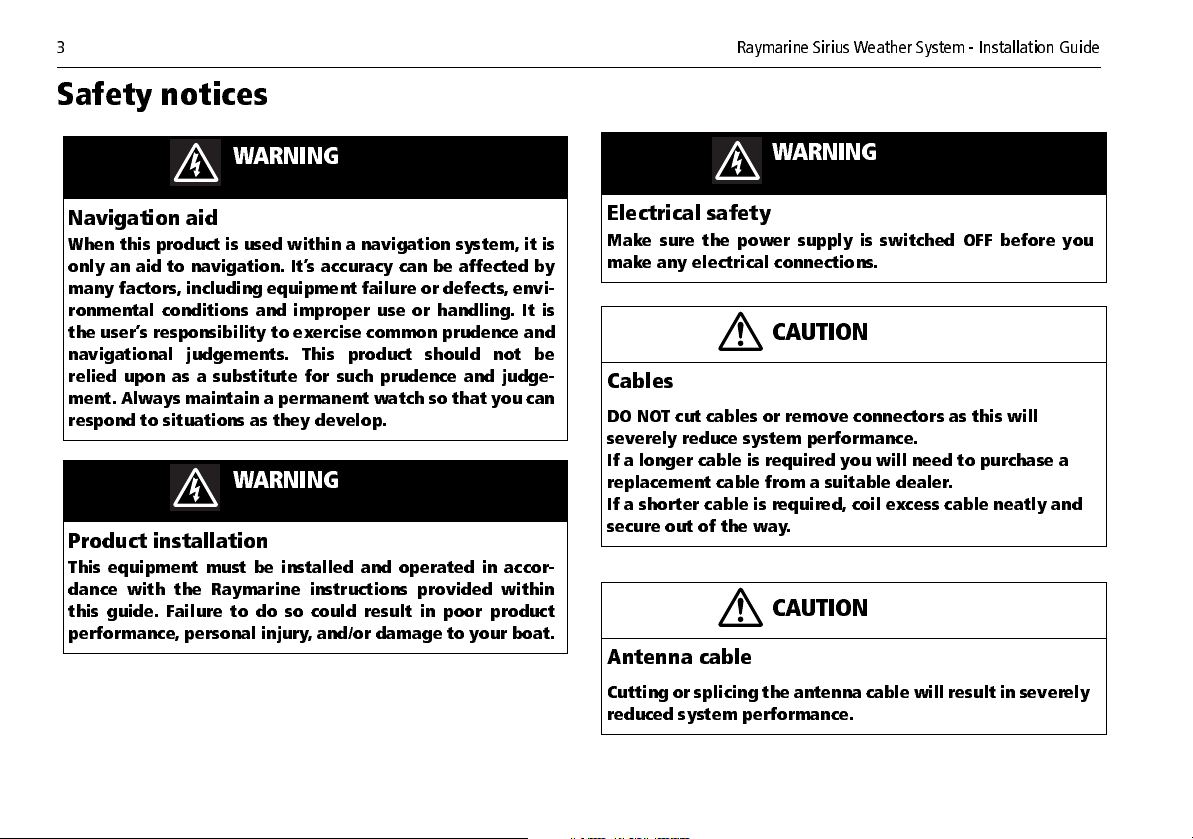
Navigation aid
When this product is used within a navigation system, it is
only an aid to navigation . It’s accuracy can be af fect ed by
many factors, including equipment failure or defects, envi
ronmental con ditions and imp roper use or handlin g. It is
the user’s responsibility to exercise common prudence and
navigational judgements. This product should not be
relied upon as a su bstitute for su ch prudence and judg e
ment. Always maintain a permanent watch so that you can
respond to situations as they develop.
WARNING
Product installation
This equipm ent must be installed and operated in accor
dance with the Raymarine instructions provided within
this guide. Failure to do so could result in poor product
performance, personal injury, and/or damage to your boat.
Electrical safety
Make sure the power su pply is switched OFF before you
make any electrical connections.
CAUTION
Cables
DO NOT cut cables or remove connectors as this will
severely reduce system performance.
If a longer cable is required you will need to purchase a
replacement cable from a suitable dealer.
If a shorter cable is required, coil excess cable neatly and
secure out of the way.
CAUTION
Antenna cable
Cutting or splicing the antenna cable will result in severely
reduced system performance.
Page 7
Safety notices 4
CAUTION
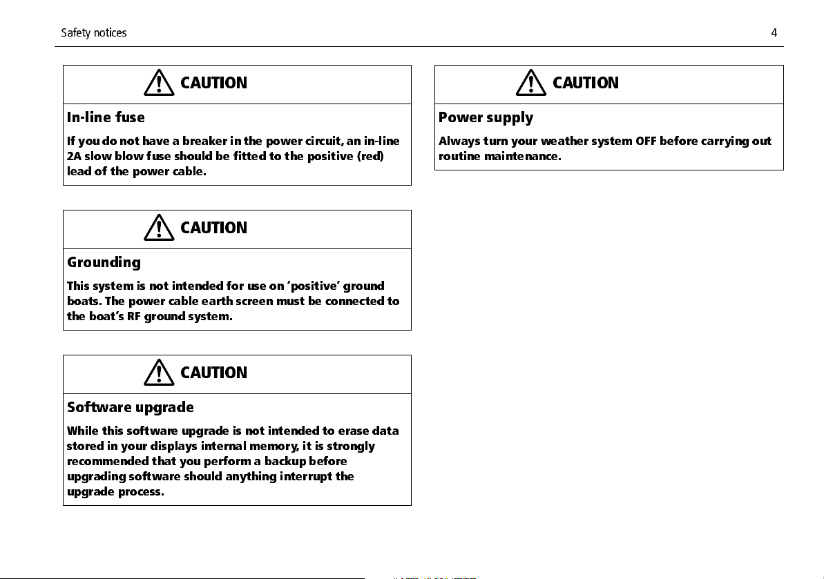
Inline fuse
If you do not have a breaker in the power circuit, an inline
2A slow blow fuse should be fitted to the positive (red)
lead of the power cable.
CAUTION
Grounding
This system is not intended for use on ‘positive’ ground
boats. The power cable earth screen must be connected to
the boat’s RF ground system.
CAUTION
Software upgrade
While this software upgrade is not intended to erase data
stored in your displays internal memory, it is strongly
recommended that you perform a backup before
upgrading software should anything interrupt the
upgrade process.
CAUTION
Power supply
Always turn your weather system OFF before carrying out
routine maintenance.
Page 8
5 Raymarine Sirius Weather System Installation Guide
Installation
EMC Installation Guidelines
Raymarine equipment and accessories are designed to the best industry
standards for use in the recreational marine environment.
Their design and manufacture conforms to the appropriate Electromagnetic
Compatibility (EMC) regulations, but correct installation is required to
ensure that performance is not compromised.
The guidelines given here describe the conditions for optimum EMC perfor
mance, but it is recognized that it may not be possible to meet all of these
conditions in all situations. To ensure the best possible conditions for EMC
performance within the constraints imposed by any location, always ensure
the maximum separation possible between different items of electrical
equipment.
For
optimum
possible
• Raymarine equipment and the cables connected to it are:
• At least 3 ft. (1 m) from any equipment transmitting or cables
• More than 7 ft. (2 m) from the path of a radar beam. A radar beam
• The product is supplied from a separate battery from that used for
engine start. Power supply voltages below the minimum specified for a
product, and starter motor transients, can cause the product to reset.
This will not damage the product, but may cause the loss of some
information and may change the operating mode.
EMC performance, it is recommended that
:
carrying radio signals e.g. VHF radios, cables and antennas. In the
case of SSB radios, the distance should be increased to 7 ft. (2 m).
can normally be assumed to spread 20 degrees above and below
the radiating element.
wherever
• Raymarine specified cables are used. Cutting and rejoining these
cables can compromise EMC performance and must be avoided unless
doing so is detailed in the installation manual.
Suppression Ferrites
If a supplied cable is fitted with a suppression ferrite, the ferrite must not
be removed, unless it is necessary to facilitate installation. Any ferrite thus
removed must be replaced in the original position immediately installation
is complete.
If additional suppression ferrites are required, use only ferrites supplied by
Raymarine.
Connections to Other Equipment
If Raymarine equipment is to be connected to other equipment using a
cable not supplied by Raymarine, a Raymarine suppression ferrite MUST
always be attached to the cable near the Raymarine unit.
Page 9
6
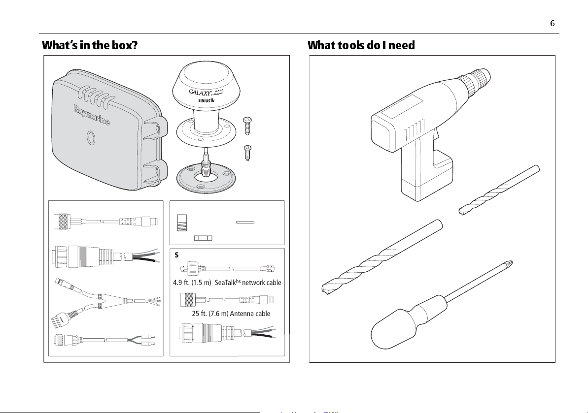
4.9 ft. (1.5 m) SeaTalk
hs
network
cable
25 ft. (7.6 m) Antenna cable
SR100
SR50
SR50 and SR100
10 ft. (3 m) Power cable
25 ft. (7.6 m) Antenna cable
10 ft. (3 m) Power cable
SeaTalk
NG
network Y-cable
Audio cable
D9061-1
M8
screw (x4)
M3.5
screw (x3)
SRA-40
Antenna
Mounting
gasket
Weather
receiver module
Surface mount kit
Extension
shaft
Lock
washer
Retaining nut
What’s in the box? What tools do I need
Drill
7/64" Drill bit
9/16" Drill bit
Phillips
screwdriver
D9062-1
Page 10
7 Raymarine Sirius Weather System Installation Guide
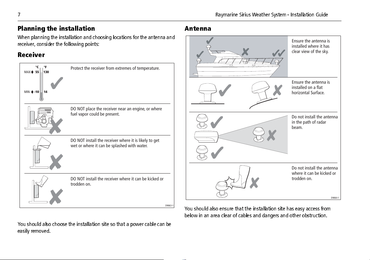
Plan ni ng th e ins t al la tio n
When planning the installation and choosing locations for the antenna and
receiver, consider the following points:
Receiver
MAX
MIN
130
-105514
You should also choose the installation site so that a power cable can be
easily removed.
Protect the receiver from extremes of temperature.
DO NOT place the receiver near an engine, or where
fuel vapor could be present.
DO NOT install the receiver where it is likely to get
wet or where it can be splashed with water.
DO NOT install the receiver where it can be kicked or
trodden on.
D9063-1
Antenna
Ensure the antenna is
installed where it has
clear view of the sky.
Ensure the antenna is
installed on a flat
horizontal Surface.
Do not install the antenna
in the path of radar
beam.
Do not install the antenna
where it can be kicked or
trodden on.
D9064-1
You should also ensure that the installation site has easy access from
below in an area clear of cables and dangers and other obstruction.
Page 11
8
Cable runs
CAUTION
Cables
DO NOT cut cables or remove connectors as this will
severely reduce system performance.
If a longer cable is required you will need to purchase a
replacement cable from a suitable dealer.
If a shorter cable is required, bundle excess cable neatly
and secure out of the way ensuring not to exceed the
minimum bend radius of 25mm.
Consider the following points before installing the system cables:
• You will need to connect the antenna, ethernet and power cables to
the receiver.
• All cables should be adequately clamped and protected from physical
damage and exposure to heat.
• Avoid running cables through bilges or doorways, or close to moving
or hot objects.
Note:
Acute bends must be avoided minimum bend radius 25mm.
• Where a cable passes through an exposed bulkhead or deckhead, a
watertight gland or swan neck tube should be used.
• DO NOT cut the cables or remove the connectors.
• DO NOT pull cables through bulkheads using a cord attached to the
connector. This could damage the connector.
• Secure cables in place using tiewraps or lacing twine. Bundling cables
in a way not to produce sharp bends as this can adversely effect the
performance of the SR50/SR100
You will need to run the following cables:
• Power cable.
hs
• SeaTalk
• SeaTalk
network cable (SR100 only)
NG
network cable (SR50 only
)
• Antenna cable.
• Audio Cable (SR50 only)
Power cable
A 10 ft. (3m) power cable is supplied. This cable has a connector plug for
connecting to the weather receiver at one end and three wires at the other
for connecting to your boats power supply. This cable may be extended to
a distance of 60 ft. (20m) using a suitable wire, gauge AWG 12 or greater.
For full details of power connections refer to “Power cable” on page 15.
SeaTalkhs network cable (SR100 only)
A 4.9 ft. (1.5m) network cable is supplied. This cable should be used to
connect your SR100 weather receiver to either a SeaTalk
or cross over coupler to connect to your ESeries display or GSeries
processor. If a longer cable is required it should be purchased from your
local Raymarine dealer. For full details of available cable lengths refer to
“SeaTalkhs (SR100 Specific)” on page 16.
hs
Network Switch
SeatalkNG network cable(SR50 only)
A 10ft (3M) Ycable is supplied.This cable makes up a complete terminated
NG
Seatalk
connect your SR50 weather receiver to your Cseries display and also
supply power to the SeaTalk
should be purchased from your local Raymarine dealer. The cable supplied
network and power solution. This cable should be used to
NG
network. If a longer cable is required it
Page 12
9 Raymarine Sirius Weather System Installation Guide
with the product is used only if the case is that there are no other existing
NG
SeaTalk
this case separate accessory cables needs to be purchased.
, SeaTalk2 or NMEA2000 products being used in the system, in
Audio cable (SR50 only)
A 5ft (1.5m) cable is supplied. The audio cable should be used to connect
your SR50 weather receiver to your external audio device.
Antenna cable
An antenna cable of 25 ft. (7.5m) is supplied. This RF coax cable should be
used to connect the antenna to the weather receiver. If a longer cable is
required it should be purchased from your Shakespeare dealer. For full
details of available cable lengths refer to “Accessories” on page 21.
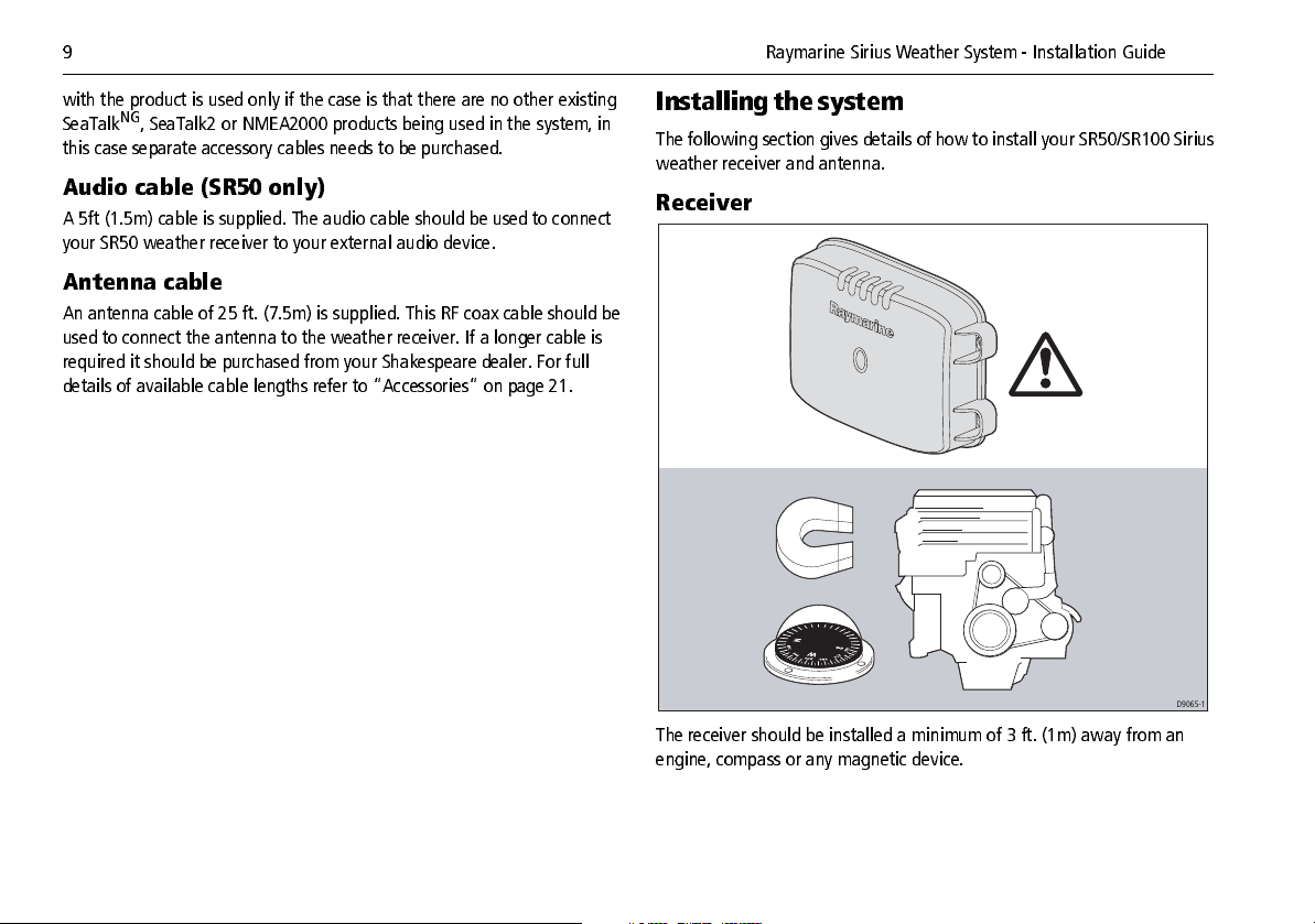
Installing the system
The following section gives details of how to install your SR50/SR100 Sirius
weather receiver and antenna.
Receiver
D9065-1
The receiver should be installed a minimum of 3 ft. (1m) away from an
engine, compass or any magnetic device.
Page 13

10
Check
Step 1
x4
A minimum 6" space must be left
below the unit to ensure adequate
space for cable bends/ connections.
Check
Vertical
6"
D9066-1
Step 2
Step 3
x4
Use 7/64" drill bit
for pilot holes
D9067-1
x4
No.8 x 3/4"screw (x4)
D9068-1
Page 14
11 Raymarine Sirius Weather System Installation Guide
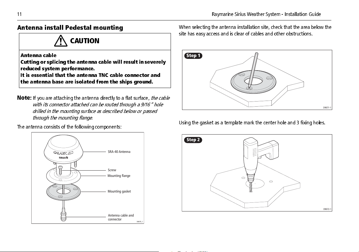
Antenna install Pedestal mounting
CAUTION
Antenna cable
Cutting or splicing the antenna cable will result in severely
reduced system performance.
It is essential that the antenna TNC cable connector and
the antenna base are isolated from the ships ground.
Note:
If you are attaching the antenna directly to a flat surface,
with its connector attached can be routed through a 9/16” hole
drilled in the mounting surface as described below or passed
through the mounting flange.
The antenna consists of the following components:
SRA-40 Antenna
Screw
Mounting flange
Mounting gasket
the cable
When selecting the antenna installation site, check that the area below the
site has easy access and is clear of cables and other obstructions.
Step 1
D9071-1
Using the gasket as a template mark the center hole and 3 fixing holes.
Step 2
Antenna cable and
connector
D9072-1
D9070_1
Page 15
12
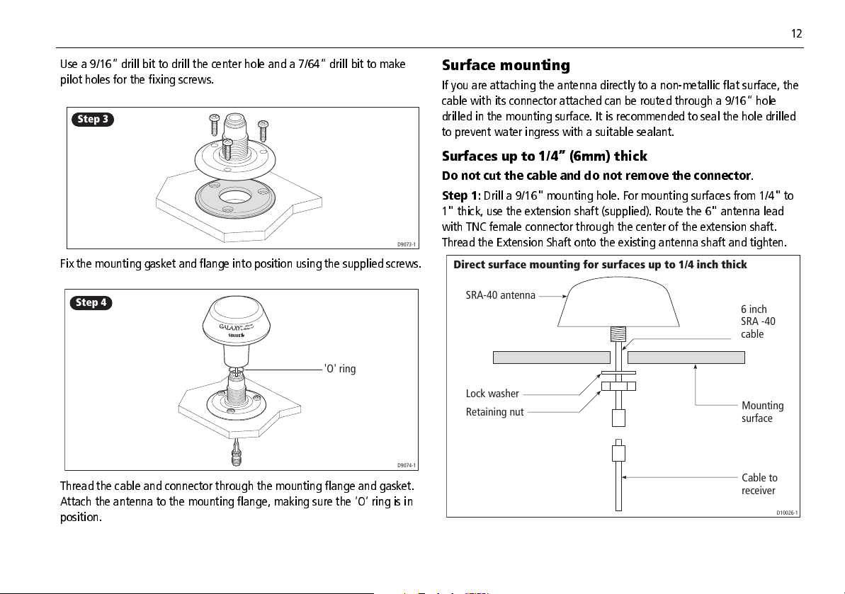
Use a 9/16” drill bit to drill the center hole and a 7/64” drill bit to make
pilot holes for the fixing screws.
Step 3
D9073-1
Fix the mounting gasket and flange into position using the supplied screws.
Step 4
'O' ring
D9074-1
Thread the cable and connector through the mounting flange and gasket.
Attach the antenna to the mounting flange, making sure the ‘O’ ring is in
position.
Surface mounting
If you are attaching the antenna directly to a nonmetallic flat surface, the
cable with its connector attached can be routed through a 9/16” hole
drilled in the mounting surface. It is recommended to seal the hole drilled
to prevent water ingress with a suitable sealant.
Surfaces up to 1/4” (6mm) thick
Do not cut the cable and do not remove the connector
Step 1:
Drill a 9/16" mounting hole. For mounting surfaces from 1/4" to
1" thick, use the extension shaft (supplied). Route the 6" antenna lead
with TNC female connector through the center of the extension shaft.
Thread the Extension Shaft onto the existing antenna shaft and tighten.
Direct surface mounting for surfaces up to 1/4 inch thick
SRA-40 antenna
Lock washer
Retaining nut
.
6 inch
SRA -40
cable
Mounting
surface
Cable to
receiver
D10026-1
Page 16

13 Raymarine Sirius Weather System Installation Guide
Step 2:
Pass the connector, cable, and shaft (if used) from the SRA40
through the hole Surfaces 1/4” (6mm) to 1” (25.4mm) thick
.
Direct surface mounting for surfaces 1/4 to 1 inch thick
SRA-40 antenna
Extension shaft
Lock washer
Retaining nut
Note:
A standard 1” x 14TPI generic rail mount is also available. Refer to
individual manufacturers installation guides for fitting instructions.
6 inch
SRA -40
cable
Mounting
surface
Cable to
receiver
D10027-1
Page 17

14
System connections
This section deals with connecting your SR50/SR100 Sirius weather system after installation.
Typical Sirius weather systems are shown in the following illustrations.
SR50
SR50
C-Series Display
Power Supply
PAGE
ACTIVE
WPTS/
MOB
DATA
MENU
OUT
RANGE
IN
CANCELOK
Amplifier
Antenna
Weather Receiver
D9939-1
SR100
Antenna
Power Supply
Weather Receiver
E-Series Display
Network Switch
Other SeaTalk
SeaTalk
devices
PAGE
ACTIVE
WPTS
MOB
DATA
MENU
OUT
RANGE
IN
CANCELOK
hs
hs
D9075_1
Page 18

15 Raymarine Sirius Weather System Installation Guide
•
Power
Connector panel
The connector panel of the receiver provides the following connection
sockets:
SR50 system
SEATALK NG
AUDIO
POWER
ANTENNA
•
•
•
The connector panel also contains a light emitting diode (LED) to indicate
system status for diagnostic purposes. For full details of the status LED
for connecting the system to your boat’s DC power supply.
hs
SeaTalk
for connecting the receiver to your boat’s SeaTalk HS
Network.
Antenna
Audio
for connecting the antenna to the system.
not used.
refer to “Status LED” on page 20
Power cable
D9940-1
•
Power
for connecting the system to your boat’s DC power supply.
NG
•
SeaTalk
display (also required to be connected to power supply to provide
power to the SeaTalk
•
Antenna
•
Audio
Network Ycable
NG
bus).
for connecting the antenna to the system.
for connecting to an audio output device i.e. Power Amplifier.
for connecting the receiver to your
The connector panel also contains a Light Emitting Diode (LED) to indicate
system status for diagnostic purposes. For full details of the status LED
refer to “Status LED” on page 20.
SR100 system
SEATALK HS
AUDIO
POWER
ANTENNA
Inline fuse
If you do not have a breaker in the power circuit, an inline
2A slow blow fuse should be fitted to the positive (red)
lead of the power cable.
Sirius weather systems are intended for use on your boats’ DC power
system. With an operating range of 9 V to 32 V.
There is no power switch on the SR50/SR100 Sirius weather receiver, it
automatically turns on when the system is powered.
The power connection for your system should be made at either the output
of the battery isolator switch, or at a DC power distribution panel. The
CAUTION
power must be fed directly to the system through its own dedicated cable
system and MUST be protected by a thermal circuit breaker or fuse,
installed close to the power connection.
D9076-1
A 10 ft. (3 m) cable is supplied with your system for connecting to the
boat’s DC power supply as follows:
Page 19

16
_
Red (12/24 V/+)
Black (0V-)
Shield (0V/ ground /-)
D9077
Extending the power cable
The power cable may be extended up to a maximum length of 60 ft. (20m)
using a suitable AWG 12 multistranded cable.
Note:
If the power connections are accidentally reversed the system will
not work. Raymarine recommends using a multimeter to ensure
that the power lead is connected with the correct polarity.
Grounding the system
CAUTION
Grounding
This system is not intended for use on ‘positive’ ground
boats. The power cable earth screen must be connected to
the boat’s RF ground system.
Your boat’s power system should be either:
• Negative grounded, with the negative battery terminal connected to
the boat’s ground, or
• Floating with neither battery terminal connected to the boat’s ground.
It is important that an effective RF ground is connected to your weather
system.
You must ground your weather system by connecting the Shield wire
(screen) of the power cable to the nearest ground point on your boat’s RF
system.
If you need to extend the wire, the extension wire should be an 8 mm braid
or AWG 10 multistrand cable.
If your boat does not have an RF system, connect the Shield wire (Screen)
to the negative battery terminal.
SeaTalkhs (SR100 Specific)
The supplied SeaTalkhs high speed network cable should be connected
from the receiver to a SeaTalk
to enable connection to your Raymarine display.
SR100
E Series Display
Crossover Coupler
hs
SeaTalk
Cable SeaTalk
hs
switch or a crossover coupler (as shown)
SR100 Weather Receiver
E55060
hs
Cable
Antenna
D9084-1
Page 20

17 Raymarine Sirius Weather System Installation Guide
SeaTalkNG Network Ycable (SR50 Specific)
The supplied SeaTalk
receiver to the relevant port at the rear of your Raymarine CSeries display
it is also to provide the SeaTalk
SR50
2
K
L
A
T
A
E
S
R
E
W
O
P
To
power
supply
Amplifier
NG
network Ycable should be connected from the
C-Series Display
G
Y
R
K
L
A
T
A
E
S
R
A
D
A
R
NG
network with power.
M
S
D
A
E
M
IN / OUT
N
SeaTalk
SR50 Weather Receiver
NG
Cable
Antenna
D9083-1
Antenna cable
The antenna cable should be used to connect the antenna to the weather
receiver. If a cable length greater than the 25 ft. (7.5 m) supplied is
required a substitute cable of suitable length should be purchased from
your Shakespeare dealer ensuring that a maximum length of 90 ft. (27.4 m)
is not exceeded. If this maximum is exceeded then this will cause the unit
to operate either poorly or not at all.
CAUTION
Antenna cable
Cutting or splicing the antenna cable will result in severely
reduced system performance.
Page 21

18
System activation
With your Sirius weather system correctly installed, this section details how
to activate Sirius weather application on your display.
Activation
With the weather system and your display powered ON:
1. Open a weather application page on your display and make it active. For full details of how to do this, refer to the relevant display handbook.
2. Press the
3. Use the trackpad to highlight
4. Use the trackpad to enter
MENU
key. The Setup dialog box appears.
Setup
Weather Setup Menu...
System Setup...
Alarm Setup...
Weather Setup Menu
Weather Setup Menu
Weather Setup Menu
Sirius Weather ID XXXXXXXXX
Wind Symbol Arrow
Marine Watchbox Alerts 150nm
9078_1
D
.
.
D9079_1
6. Contact Sirius Weather at
1800 86 9 54 80
to activate your system.
Your Sirius Weather ID number is displayed on the first line of the
Weather Setup Menu.
5. Make a note of your Sirius Weather ID number.
Page 22

19 Raymarine Sirius Weather System Installation Guide
Upgrading weather receiver software
The following section gives details of how to carry out an upgrade of your
SR50/SR100 weather receiver software.
Note:
Upgrades made to the SR50 can take approximately 20 Mins.
CRITICAL!
The SR50/SR100 weather receiver unit MUST remain
powered on for ten minutes after the upgrade is complete.
Failure to do so could result in incomplete processing of
the upgrade and subsequently the SR50/SR100 will not
properly reboot. The unit would then have to be returned
to Raymarine for reprogramming.
Before upgrading your weather receiver software, 2 pieces of hardware are
necessary to complete this process:
• A blank CompactFlash (CF) memory cartridge of 8 Megabytes capacity
or larger. Raymarine recommends using SanDisk brand CF cards.
• A CF reader/writer device for your PC or Mac. This device will be used
to copy the files downloaded from Raymarine.com to the CF card.
The CF reader/writer can be an external device (e.g. connected by USB
to your computer), or can be internal/built in.
Downloading the software upgrade
1. Point your web browser to
2. Navigate to
3. Download the latest version for your SR50/SR100 weather receiver.
4. Follow the onscreen instructions.
Customer support
http://www.raymarine.com
then
Software update
pages.
Uploading software to your weather receiver
Ensure your SR50/SR100 weather receiver and display are powered
1. Power up your display and SR50/SR100 unit. Wait until the Sirius
disclaimer is displayed then power down your
SR50/SR100 should remain powered with the Status LED flashing
amber.
2. Insert a CF card containing the software upgrade into the display. Power up your display, you will see the Upgrade Utility screen. Ensure the software upgrade version is highlighted in the left hand column, if not use the trackpad to do so.
3. Press the
4. Press the
“ST2” (SR50).The Upgrade progress bar appears.
The progress bar will begin updating. If they do not begin updating
within 30 seconds, check:
i. that the correct software revision was selected.
ii. that the SR50/SR100 weather receiver is powered
iii. that the Display/weather receiver data cable connection is intact.
5. When the update process is complete, remove the CF card from the card reader slot.
6. Press the
Read Critical Warning
and display are now ready for normal operation. For full details of how
to operate your SR50/SR100 Weather Application refer to the relevant
display manual. A copy of this manual is available from the relevant
product pages at
Upgrade Remote Unit
Upgrade Remote Unit
LED is flashing as per item 2 above.
REBOOT
soft key. Your display will restart automatically.
www.raymarine.com
soft key.
on “Ethernet” soft key (SR100) or
! Your SR50/SR100 weather receiver system
display only
ON
. The
and status
OFF
:
Page 23

20
Maintenance and troubleshooting
Introduction
This section provides information on routine maintenance and trouble
shooting that can be carried out by the user.
Maintenance
CAUTION: Power supply
Always turn your weather system OFF before carrying out
routine maintenance.
Your SR50/SR100 Sirius weather unit is a sealed unit!
cover of the receiver. Adjustments require specialized service procedures
and tools only available to qualified service technicians. There are no user
serviceable parts or adjustments.
Routine checks
Routine checks are limited to the following periodical checks:
• Examine the cables for signs of damage, such as chafing, cuts, or nicks.
• Check that the cable connectors are firmly attached and dust caps are
fitted to any connection not in use.
Cleaning
If you find it necessary to clean the unit, follow these basic procedures:
• Wipe the module clean with a damp cloth.
• If necessary, use isopropyl alcohol (IPA) or a mild detergent solution to
remove any grease marks.
DO NOT
remove the
Troubleshooting
Your Raymarine product, prior to packing and shipping, has been subjected
to comprehensive test and quality assurance programs. However, if the
unit should develop a fault, please refer to the following section to identify
the most lik ely c ause and the corre ctive a ction re quired to restore norma l
operation. If you still have a problem after referring to the following
section, c ontact your local deale r, nationa l distributor or Rayma rine T ech
nical Services Department for further advice.
Status LED
The LED on the connector panel provides valuable information on the
status of your Sirius Weather system.
The LED blinks green while the system is operating n ormally. If the unit
detects a proble m, the LED blinks amber to indic ate a warning or red to
indicate a n error. The patt ern of the LED blink is a code representing the
nature of the probl em. For multi ple wa rnings/er rors the cod es a re g iven in
sequence with a 1.5 second pause between the indications.
The following table shows the LED status codes and their meanings:
LED color LED pattern Description
Green Blinking Normal operation
Amber 1sec ON, 2 sec. OFF Antenna disconnected
Amber 1 sec. ON, 1 sec. OFF, 1 sec.
ON, 2 sec. OFF
hs
SeaTalk
disconnected
cable
Page 24

21 Raymarine Sirius Weather System Installation Guide
LED color LED pattern Description
Red Blinking Internal fault
Amber Solid 1st Minute of power
up(SR50)
It is normal during the f irst mi nute of i nitia l pow e r that the rec ei ver status
LED shows no activity and remains off. During the second minute the status
LED will start to flash the amber or red fault strings. Typically, during
normal operati on, a flashing green LED will occ ur within 90 seconds of
initial powe r. If there is no LED indication of any sort d isplayed after 90
seconds you should check the inline fuse or circuit breaker.
A blinking
Red
LED indica tes an internal fa ult condition. If this conditi on
persists contact Raymarine Technical Services.
Accessories
The following accessories are available from your local dealer, national
distributor or Raymarine Customer Service Department:
Part No. SR100 Cables
E55049
E55050
1.5 m SeaTalk
5 m SeaTalk
hs
Network cable
hs
Network cable
Part No. SR100 Cables
E55051
E55052
10 m SeaTalk
20 m SeaTalk
hs
Network cable
hs
Network cable
Part No. SR50 Cables
R69053
3 m for SeaTalk
NG
Network Ycable (Network and Power)
R08265 1.5m Audio cable
The following accessories are available from your local Shakespeare dealer:
Part No Antenna Accessories
SRS35 35 ft. antenna cable and connectors
SRS50 50 ft. antenna cable and connectors
SRS90 90 ft. antenna cable and connectors (Maximum
recommended).
SRA40 Sirius Antenna
Page 25

22
Technical support
www.raymarine.com
United States
Raymarine Technical Support
1- 603 - 881- 5200
Product Repair and Service
Raymarine Product Repair Center
21 Manchester Street,
Merrimack, NH 03054 - 4801
1- 603 - 881- 5200
Opening hours:
Monday through Friday 0815 - 1700
Eastern Standard or Eastern Daylight
Savings Time.
Help us to help you
When requesting service, please quote the following product information:
Equipment type Model number Serial number
D9080-2
Page 26

23 Raymarine Sirius Weather System Installation Guide
Glossary of weather terms
Term
Cold front
Cyclone A large area of low atmospheric pressure, characterized by inwardspiralling winds. A “low” also called a “depression”. Also the
Depression
Dry line
Forecast Something that tells us what the weather is probably going to be like .
Fron t The boundar y between two masses of air with different temperatures (i.e .: a mass of cold air and a mass of warm air).
High Also known as an 'anticyclone' an area of high atmospheric pressure with a system of winds rotating outwards. This usually
High Pressure A mass of air that presses down strongly on the surface of the Earth because it is being cooled and is therefore more dense.
Definition
The boundary between two different air masses where cold air pushes warm air out of the way and brings colder weather .
name used for a hurricane in the Indian Ocean and Western Pacific.
An area of low pressure. Also called a cyclone.
A region where ther e is a stron g gradient in dew point temp eratures. It is oft en found in a region where str ong thund erstorms d evelop.
means dry weather . It is the opposite of a 'low'.
Page 27

24
Term
Hurricane A violent, spiralling storm that forms over the Atlantic Ocean, with winds over 120 kph. Such storms usuall y have a lifespan o f sev
Definition
eral days . Also known as a typ hoon or tro pical cyclone . T here are 5 levels o f hurri cane:
Category 1
Winds 7495 mph (6482 kt or 119153 km/hr). Storm surge generally 45 ft above normal. No real damage to building struc
tures. Damage primarily to unanchored mobile homes, shrubbery, and trees. Some damage to poorly constructed signs. Also ,
some coastal road flooding and minor pier damage.
Cate gory 2
Winds 96110 mph (8395 kt or 154177 km/hr). Storm surge generally 68 feet above normal. Some roofing material, door , and
window damage of buildings. Considerable damage to shrubbery and trees with some trees blown down. Considerable dam
age to mobile homes, poorly constructed signs, and piers. Coastal and lowlying escape routes flood 24 hours before arrival of
the hurricane centre Small craft in unprotected anchorages break moorings.
Cate gory 3
Winds 111130 mph (96113 kt or 178209 km/hr). Storm surge generally 912 ft above normal. Some structural damage to
small residences and utility buildings with a minor amount of curtainwall failures. Damage to shrubbery and trees with foliage
blown off trees and large trees blown down. Mobile homes and poorly constructed signs are destroyed. Lowlying escape
routes are cut by rising water 35 hours before arrival of the centre of the hurricane. Flooding near the coast destroys smaller
structures with larger structures damaged by battering from floating debris. T errain continuously lower than 5 ft above mean
sea level may be flooded inland 8 miles (13 km) or more. Evacuation of lowlying residences with several blocks of the shoreline
may be required.
Cate gory 4
Winds 131155 mph (114135 kt or 210249 km/hr). Storm surge generally 1318 ft above normal. More extensive curtainwall
failures with some complete roof structure failures on small residences. Shrubs, trees, and all signs are blown down. Complete
destruction of mobile homes. Extensive damage to doors and windows. Lowlying escape routes may be cut by rising water 35
hours before arrival of the centre of the hurricane. Major damage to lower floors of structures near the shore. Terrain lower than
10 ft above sea level may be flooded requiring massive evacuation of residential areas as far inland as 6 miles (10 km).
Page 28

25 Raymarine Sirius Weather System Installation Guide
Term
Definition
Cate gory 5
Winds greater than 155 mph (135 kt or 249 km/hr). Storm surge generally greater than 18 ft above normal. Complete roof fail
ure on many residences and industrial buildings. Some complete building failures with small utility buildings blown over or
away. All shrubs, trees, and signs blown down. Complete destruction of mobile homes. Severe and extensive window and door
damage. Lowlying escape routes are cut by rising water 35 hours before arrival of the centre of the hurricane. Major damage
to lower floors of all structures located less than 15 ft above sea level and within 500 yards of the shoreline. Massive evacuation
of residential areas on low ground within 510 miles (816 km) of the shoreline may be required.
Isobar A line on a weather map linking areas with equal air pressure.
Lightning Discharge of static electricity in the atmosphere, usually between the ground and a storm cloud.
Low Also called a 'depression' this region of low pressure can mean wet weather.
Low Pressure A mass of air that presses down only weakly on the surface of the Earth’s surface as it is warmed and it therefore less dense.
Millibar A unit used to measure atmospheric pressure.
Occluded Front An area where warm air is pushed upwards as a cold front overtakes a warm front and pushes underneath it.
Precipitation Moisture that is released from the atmosphere as rain, drizzle, hail, sleet or snow, as well as dew and fog.
Pressure Centre A region of high or low pressure.
Page 29

26
Term
Definition
Squall line A nonfrontal band, or line, of thunderstorms.
Super typhoon A typhoon that reaches maximum sustained 1minute surface winds of at least 65 m/s (130 kt, 150 mph). This is the equivalent of
a strong category 4 or 5 hurricane in the Atlantic basin or a category 5 severe tropical cyclone in the Australian basin.
Tornado A funnelshaped whirlwind which extends to the ground from storm clouds.
Tropical cyclone A low pressure system that generally forms in the tropics. The cyclone is accompanied by thunderstorms and, in the Northern Hemi
sphere, a counterclockwise circulation of winds near the earth's surface.
Tropical depression An organized system of clouds and thun derstorms with a defined surface circulation and maximum su stained winds of 38 mph (33 kt)
or less .
Tropical storm An organized system of strong thunderstorms with a defined surface circulation and maximum sustained winds of 3973 mph (34
63 kt).
Tropics An area on the Earth's surface that lies between 30º north and 30º south of the equator.
Tro ugh An elonga ted area of relatively low atmospheric pressur e, usually extend ing from the centre of a low pressure region.
Typhoon The name for a tropical storm originating in the Pacific Ocean, usually the China Sea. They are basically the same as the hurricanes
of the Atlantic Ocean and the cyclones of the Bay of Bengal.
Wave cyclone A storm or lowpressure centre that moves along a front.
Page 30

27 Raymarine Sirius Weather System Installation Guide
Using the Weather application
Introduction
This chapter is intended to give an overview of how to operate the Weather
application of your C or ESe rie s display and is appli ca ble to systems being
operated in US waters only.
Note:
Ensure you have the latest up to date version of the handbook for
your individual Display (C/ESeries) which can be accessed online
at www.raymarine.com look for the Manuals under Customer
Support. Software upgrades may take place changing the opera
bility of the software as described in this handbook.
Overview
Using your Sirius wea ther receiver to obtain the data, re gularly updated
forecasts and warnings with details of current and expected weather condi
tions can be seen on your display.
The wea ther application enables you to ove rlay historical, live and fore
casted wea ther gra phic s over a worl d map on your C or ESer ies displ ay. It
also provides forecasts and warnings in a text format.
Setting up the application
Before you are able to use the w eather appl ication you will nee d to make
sure that the following steps have been carried out:
• Your Sirius Weather Receiver has been installed and connected in
accordance with the instructions contained in the Installation and
Connection sections of this handbook.
• Your C or ESeries display is running a version of software that includes
the weather application.
• You have obtained a Sirius ID number and activated the system as
detailed in “System activation” on page 18 of this handbook.
• Your C or ESeries display has obtained a GPS fix on your boat’s
position.
With all of the above steps complete d you now need to set up your system
to show the required weather information. To do this you need to:
• Customize a page set.
• Configure your weather application.
• Specify the information displayed.
Customize a page set
The weather application does not appear in a preconfigured page set. You
need to set up a page set to include a weather application window.
For full details of how to customiz e a page set re fe r to the rele vant displa y
handbook.
Configure your weather application
With an active window showing the weather application you can
customize the configuration to suit your particular method of working.
Although you will probably only nee d to do this the first time you use the
weather applica tion, you are able to make changes at any time you w ant
to. Any changes are retained by the system even when powered Off.
To configure your weather application:
1. Press
MENU
. The Set up dialog box appears.
Page 31

28
NOWRad
O
2. Press trackpad
3. Press trackpad
4. Press trackpad
5. Press trackpad
Up/Down
Right
Sirius Weather User ID
Wind Symbol Arrow
Marine Watchbox Alerts 150nm
Up/Down
Right
Setup
Weather Setup Menu...
GPS Setup...
Compass Setup...
to highlight
Weather Setup Menu
.
. The Weather Setup Menu appears.
Weather Setup Menu
to highlight
Wind Symbol.
. The Wind Symbol options of barbs or arrows
appear.
6. Press trackpad
7. Press trackpad
Up/Down
Up/Down
to select Wind Symbol style.
to highlight
Marine Watchbox Alerts
.(These
are the automatic watchboxes).
8. Press trackpad
Right
. The Watchbox alert area options appear.
The options are OFF, 50,150,300, 500 and All. The figures represent the
range from your boat and are dependant on your system settings.
9. Press trackpad
Up/Down
to highlight the selected range.
10. Press OK. The Weather Setup Menu closes.
You now need to configure Marine Zones and Watchbox Graphic Display as
Show/Hide.
The default for these is SHOW.
To configure marine zones and watchboxes:
1. Press
2. Toggle the
3. Toggle the
4. Press
Presentation
OK
. The Marine Zones and Watchbox soft keys appear.
Watchbox
Marine Zones
softkey to ON or OFF as required.
soft key to HIDE or SHOW as required.
to accept your choice and return to the top level soft keys.
Specify the information displayed
You need to spec if y the w ea ther repo rts or gra phic s that a re shown in the
weather application using the Weather Setup Menu.
To set up reports and graphics:
1. Open a weather application window.
2. Press
3. Press the trackpad
4. Press the trackpad
5. Press the trackpad
6. Press OK to accept the options.
7. Repeat Steps 1 through 6 until all required options are specified.
Display Graphics
Storm Cast OFF
Sea Surface Temp OFF
Canadian Radar OFF
Storm Tracks OFF
Lightning OFF
Surface Ob Stations OFF
Cities OFF
Wind OFF
Waves OFF
Surface Pressure OFF
Up/Down
Right
Up/Down
. The Weather Graphics menu appears.
Weather Graphics
N
to highlight the required menu item.
to select the item.
to toggle the item ON or OFF.
Page 32

29 Raymarine Sirius Weather System Installation Guide
The weather display
The main features of the weather display are:
Range Animation time/data
Signal strength
2400 nm Medium
FIND SHIP
DISPLAY
GRAPHICS...
12:00 22/11
ANIMATE
WEATHER...
WEATHER
REPORTS...
PRESENTATION...
Weather soft keys
Status
bar
Marine
zone
Surface
observation
stations
Wave
heights
Moving around the weather map
When you open the w ea ther appli ca tion, a w orld map
is shown. If your system has a valid GPS fix, the map is
shown cente red on your boat. As in the chart appl ica
tion, use the cursor to move around the map and the
range button to zoom in and out. Remember that accu
racy wi ll be lost i f you zoom o ut a long wa y. Zoom in
until all the requ ired detail is displayed. To rec enter
the map on your boat, press FIND SHIP.
Placing waypoints
The way point button and softkeys operate as normal
when you are using the weather a pplication, but you
will ne ed to change the active w indow to a chart or
radar applic ation window to see any waypoints that
you have placed.
D8564_1
Page 33

30
We ather op tions
This section det ails the available options in your weathe r application and
covers:
• NOWRad.
• Storm cast.
• Surface Sea Temperature.
• Canadian radar.
• Storm tracks.
• Lightning.
• Surface observation stations.
•Cities.
• Wind.
• Waves.
• Surface pressure.
NOWRad (Precipitation)
The NOWcasting of precipitation using
Radars (NOWRad) option shows the type
and level of precipita tion a define d in the
table below:
Color code Precipitation type Intensity
Color code Precipitation type Intensity
Dark green Rain 30 39 dBz
Yellow Rain 40 44 dBz
Orange Rain 45 49 dBz
Light red Rain 50 54 dBz
Dark red Rain 55 + dBz
Light blue Snow 5 19 dBz
Dark blue Snow 20 + dBz
Light pink Mixed 5 19 dBz
Dark pink Mixed 20 + dbz
Storm Cast
24
26
22
Speed of
storm
Direction
of storm
Storm Cast arrow s i ndi
cate the direction and
speed of a storm.
D8926_1
Light green Rain 15 19 dBz
Medium green Rain 20 29 dBz
Page 34

31 Raymarine Sirius Weather System Installation Guide
To display storm details:
1. Place the cursor at the base of the storm cast arrow. The Object information dialog box appears.
2. Press OK. The Storm cast detail informa
tion box appears.
Storm ID
Echo Top
Direction
Speed
Time
Position
Attributes
Storm cast
VXNO
5.760NM
o
T
057
1.6kl
08:40AM
24o44'.700N/079o40'.440W
Hail Confirmed
Sea surface temperature (SST)
The SS T can be shown as shadi ng, varying
from blue the coldest temperature
through shades of green, yellow and
orange to red the warmest temperature.
26
OBJECT INFO
Storm
OK for more info
Canadian radar
Canadian radar shows the precipitation
levels for Canada, but unlike NOWRad it
does not show the precipitation type.
Color code Intensity in mm per hour
Transparent
(nothing shown at very low
precipitation levels)
Light green 0.21 to 1.00 mm/hour
Medium green 1.01 to 4.00 mm/hour
Dark green 4.01 to 12.00 mm/hour
Yellow 12.01 to 24.00 mm/hour
Orange 24.01 to 50.00 mm/hour
Light red 50.01 to 100 mm/hour
0.00 to 0.20 mm/hour
Dark red 100.01 + mm/hour
Page 35

32
Storm track
You can use the STORM TRACK function to monitor significant storms in an
area. These include:
• Tropical disturbances.
• Depressions.
• Storms and cyclones.
• Hurricanes.
• Typhoons and super typhoons.
The weather application shows:
• the track the storm has taken.
• its current and forecasted positions.
• the wind radii (current position only).
• wind direction.
• speed of travel.
There are 3 symbols used to represent storms:
Hurricane
Category 1 5
Tropical storm
Tropical Depression
Each of these symbols can be displaye d onscreen in 3 diff erent colors to
show its status:
• Grey historical,
• Red current.
• Orange forecast.
Tropical storm data
You can display tropical storm data for a selected storm. This data includes:
• Storm’s name and type.
• Date and time.
• Position, direction and speed.
• Pressure and maximum wind speed and gusts.
To display tropical storm data:
1.Place the cursor over the storm symbol. The Object Information dialog box appears giving details of the storm type.
2.Press OK. The Tropical Storm Data box appears.
Tropical Storm Data
EPSILON
AL292005
Hurricane Category 2
075oT
9.9kt
64.9kt
80.1kt
987mb
12/03/2005
3:00PM
34o30'.000N/044o24'.000W
Hurricane Category 2
OK for more info
OBJECT INFO
Storm name
Storm ID
Storm Type
Direction
Speed
Max Wind Speed
Max gust Speed
Pressure
Date
Time
Position
Page 36

33 Raymarine Sirius Weather System Installation Guide
Lightning
A lightning symbol is shown at each cloud
toground strike recorded within the last 5,
10 and 15 minutes. The most recent strikes
are colored bright yellow with intermediate
and older strikes recorded in darker shades
of yellow. More recent strikes are overlaid
over older ones.
Surface observation stations
Current or historica l weather data can be
viewed at surface observation stations.
These stations are represented according
to type by a pink symbol as follows:
•Diamond Buoy station
•Triangle Coastal Marine Automated
Network (CMAN)
•Circle Weather Service International
(WSI).
•Square National Weather Service (NWS).
Remember that not all data is available for all stations.
To identify a station and display additional data:
1.Place the cursor over the relevant
OBJECT INFO
KSUT
OK for more info
surface observation station symbol.
The Object Information dialog box
appears.
2.Press OK. The Station Data infor
mation box appears.
Station Data
Time
Wind speed
Wind Direction
Wave Height
Sea Temperature
Visibility
02:36PM
19.4kt
o
t
003
13.1ft
o
50.0
F
0.540nm
Page 37

34
Cities
To display City forecasts:
OBJECT INFO
Summer Bay
OK for more info
Forecast for Summer Bay
Forecast for Monday
A mix of clouds and sun. High 22F.
Winds NNE at 5 to 10 mph.
Forecast for Monday night
Mostly coudy skies. Low near 20F.
Winds NW at 5 to 10 mph.
Forecast for Tuesday
Sunshine along with some passing clouds.
High near 25F. Winds NW at 5 to 10.
The Cities options enables you to access
details of city weather forecasts. Up to 3
forecasts are displayed for each city.
1.Place the cursor over the relevant city symbol. The Object Information dialog box appears showing the City name.
2.Press
OK
. The weather forecasts for the
selected city are shown.
Station ID
Station Name
Station Type
Latitude
Longitude
Time
Date
Air Temperature
Horizontal Visibility
Vertical Visibility
Sea Level Pressure
3 Hour Pressure Change
Pressure Tendancy
Wind Direction
Wind Speed
Peak Wind Speed
Gust Wind Speed
Water Temperature
Tidal Elevation
Wave Height
Wave Period
Dominant Swell Direction
Dominant Swell Height
Dominant Swell period
Lesser Swell Direction
Lesser Swell Height
Lesser Swell Period
Station Report
KEYW
Key West, FL
METAR Automatic
o
23
33' .000N
o
081
45'.000W
08:26AM
21/12/2005
o
68.4
F
13.53km
-,--kh
-mb
-mb
---
o
036
T
13.0kt
-,-kt
-,-kt
o
-,-
F
-,-ft
-,-ft
--h--m--s
o
---
T
-,-ft
--h--m--s
o
---
T
-,-ft
--h--m--s
3. Press View Full Report. The full station report is displayed for the selected station.
Page 38

35 Raymarine Sirius Weather System Installation Guide
Wind
This option shows the current wind direction and strength and can be
displayed as ei ther an arro w or a wi nd barb. W ind a rrow s indic ate spee d
the larger the arrow , the greater (stronger) the wind spee d. Wind barbs
give a more precise indicat ion of w ind speed a s shown on the illustrati on
below:
3-7 kts
33-37 kts
8-12 kts 13-17 kts
38-42 kts 43-47 kts
18-22 kts 23-27 kts
48-52 kts
53-57 kts
28-32 kts
63-67 kts58-62 kts
Waves
The waves option shows current wave
height in up to 16 shades of color:
•Reds Highest waves
•Greens Intermediate waves.
Blues Lowest waves
68-72 kts
73-77 kts
78-82 kts
88-92 kts83-87 kts 98-102 kts93-97 kts
Page 39

36
Surface pressure
Surface pressure can be shown using standard meteorological symbols:
High (blue) Low pressure (red)
Cold front (blue)
Stationary front (blue-red)
Squall line (red)
Warm front (red)
Occluded front (purple)
Trough (brown)
Dry line (red)
1010
Viewing weather data at a specific location
You can show the f ollowing detai ls for a particular l ocation regardle ss of
the product Show/Hide status
• Sea temperature.
• Wind speed and direction.
• Wave height.
• Precipitation type and intensity.
To view weather data at a specific location:
1. Place the cursor in the required location.
2. Press OK. The Weather information dialog box appears.
Weather Info
Zone desription
North Altantic Ocean between 31N and 67N latitude and
between the East Coast North America and 35W lonitude
Zone ID
Precipitation Intensity
Precipitation Type
Sea Surface temperature
Wind Speed
Wind Direction
Wave Height
The dialog bo x also contai ns a descripti on of the ma rine zone selec ted by
the cursor’s position.
XXX
<5dBz
None
-.-oF
20.0kt
255
-.-ft
o
T (WSW)
1012
Isobars (grey)
Animating weather graphics
Using the ani mated wea ther option you c an view an animation f rom the
current time for:
Page 40

37 Raymarine Sirius Weather System Installation Guide
• Wind, waves or surface pressure.
• NOWRad (Weather radar history loop).
To set up a weather animation:
1. Press
2. Toggle the
Animate Weather.
Animate Type
The animate weather softkeys appear.
soft key to the required option. This can be
F’CAST or N’RAD.
3. Toggle the
Forecast
soft key to the required forecast option. This can
be WIN, WAVE or PRES.
4. Toggle
Animate
to ON .
The time frame shown is detailed in the status bar. The weather radar
history provides up to 8 images of data covering the previous 2 hours at 15
minute intervals.
If at anytime you want to stop the animation, press
PAUSE
.
When an animation is running the following points should be noted:
• Information cannot be displayed by moving the cursor over a symbol.
• Range and trackpad functions remain operable provided
PAUSE
has
not been selected. However, using either of these controls will restart
the animation.
• The animation will stop if any of the function buttons is pressed, e.g.
ACTIVE
.
Viewing weather reports
The weather application can display the following reports for:
• Tropical statements
• Marine warnings.
• Marine zone forecasts.
• Marine watchbox reports.
Marine Warnings & Marine Zone Forecast can be specified at ships position
or at cursor.
These reports are accessed using the
Weather reports
soft key. Each report
type may contain several bulletins. You can scroll the window to view all of
the data.
Tropical statements
To display tropical statements:
1. Press
2. Press
Weather Reports.
Tropical Statement
The weather application softkeys appear.
. The Tropical Statement dialog box appears.
Tropical Statements
Marine warnings
You can displa y a report detaili ng current marine w arnings for U S coasta l
or near shore areas.
To display marine warnings:
1. Press
2. Press
3. Toggle
Weather Reports
Marine Warnings
Forecast at
. The weather application softkeys appear.
.
to required position CURSOR or SHIP. The Marine
Warnings dialog box appears.
Page 41

38
Marine Warnings
Marine zone forecasts
These forecasts cover:
• US coastal weather forecasts.
• US offshore forecasts.
• High seas forecasts.
• Great Lakes forecasts.
• Near Shore forecasts.
• Canadian coastal weather forecast.
The fore cast a nd warni ngs shown w ill depend upon the area o f the chart
selected.
To display marine zone forecasts:
1. Press
2. Press
3. Toggle
Weather Reports
Marine Zone Forecasts
appears.
Forecast at
. The weather application softkeys appear.
. The marine zones forecasts dialog box
to required position CURSOR or SHIP.
Marine Zone Forecasts for
Watchbox warnings
Watchbox warnings provide area specific information of tornados and
thunderstorms. You can display a report of all current watchbox warnings.
These warnings show that a weather warning is in place for a specific area.
This area is defined by the warning itself.
In addition to the wea ther report, watc hbox warnings can be shown in 2
ways:
• Automatically generated alert on receipt by the system and shown as a
popup.
• by displaying any active watchboxes as a polygon on the weather map.
Automatic watchbox warning
With the watchbox option enabled, when a tornado, thunderstorm or
similar weather system warning is received a warning is automatically
generated and popsup on screen.
You can scroll through the report using the trackpad or rotary control.
This popup will remain on screen until it is manually cleared.
Page 42

39 Raymarine Sirius Weather System Installation Guide
Warning type and
period for which
warning is valid
Watchbox report
text
To clear an automatic alert:
Press ACKNOWLE DGE. The alert is removed from the scre en, but can be
viewed manually later if required.
Marine watchbox warning
When set to SHOW, marine watchboxes highli ght any region on a map
that has a current weather alert as a red polygon.
Watchbox alert
warning area
The area of the polygon is defined by the alert.
To show watchbox data:
1.Place the cursor over the relevant
OBJECT INFO
Issue time
Date
Thunderstorm or tornado
polygon. The Object Information
dialog box appears.
2.Press
View Warning
soft key. THe
Watchbox warning appears.
Watchbox status
You can sw itc h OFF ma rine w atc hbox a larms and se t t he wa tchbox status
to Hide see “Spec ify the i nformation di splayed” on page 28, but re ports
will continue to be added to and updated in the database.
Page 43

40
Troubleshooting the weather application
Your wea ther application has been subject ed to comprehensive test and
quality assurance program s. However, if the applic ation should develop a
fault, please ref er to the f ollow ing se cti on to ide ntify the most li ke ly cause
and the correcti ve action required to restore normal operation. If you still
have a problem a fter re ferring to the follow ing sec tion, contac t your loca l
dealer, national distributor or Raymarine Technical Services Department for
further advice.
Problem Probable cause
Boat symbol not displayed No position fix
On Startup, weather map stays in
No position fix
last view and does not redraw.
During use, weather map stays in
FIND SHIP not pressed
last view and does not redraw.
FIND SHIP soft key grayed out No position fix.
Boat symbol drawn as a solid circle No heading data or Course Over
Ground (COG) available.
If weather data is not being received, check Status bar signal strength. Soft
key operation, and application functionality continues as normal.
Page 44

41 Raymarine Sirius Weather System Installation Guide
Appendix A: Technical specifications
SR100 Technical Specification
General
Environmental:
Waterproof
Operating range
Storage range
Humidity
Receiver
Size 10¾”x 7½” x 2½” (273.3 x 187.2 x 61.7 mm)
Weight 2.2 lbs (1 kg)
Mounting Four keyholed mounting tabs, screws
IPX2
o
10
C to + 50oC
o
20
C to + 70oC
up to 95% at 35
o
C noncondensing
Antenna
Φ
Size
3½” x 4¼”(including mounting flange and
gasket)
Weight 8 oz. (226 g)
Mounting Three countersunk holes, screws
Connector SMB RF
Power
Voltage
Current
Fuse
Connectors
Reverse polarity protected
9 V to 32 V DC
0.7 A at 9 V (2 A peak)
2A (recommended)
RJ45 SeaTalk
hs
3 pin Power
4 pin Audio (not used)
SMB RF Antenna
Page 45

42
SR50 Technical Specification
General
Environmental:
Waterproof
Operating range
Storage range
Humidity
IPX2
o
10
C to + 50oC
o
C to + 70oC
20
up to 95% at 35
o
C noncondensing
Receiver
Size 10¾”x 7½” x 2½” (273.3 x 187.2 x 61.7 mm)
Weight 2.2 lbs (1 kg)
Mounting Four keyholed mounting tabs, screws
Power
Voltage
Current
Fuse
Reverse polarity protected
9 V to 32 V DC
0.7 A at 9 V (2 A peak)
2A (recommended)
Antenna
Size
Φ
3½” x 4¼”(including mounting flange and
gasket)
Weight 8 oz. (226 g)
Mounting Three countersunk holes, screws
Connector SMB RF
Connectors
6 pin SeaTalk
NG
3 pin Power
4 pin Audio
SMB RF Antenna
Page 46

43 Raymarine Sirius Weather System Installation Guide
Appendix B: List of Abbreviations
Abbreviation Description
AWG American Wire Gauge
CF CompactFlash
CMAN Coastal Marine Automated
Network
COG Course Over Ground
DC Direct current
EMC Electromagnetic Compatibility
FCC Federal Communications
Commission
ft. feet
IMO International Maritime
Organization
LED Light Emitting Diode
o
C
Degrees Centigrade
RF Radio Frequency
SMB Sub Miniature B
SOLAS Safety of Life at Sea
SST Surface Sea Temperature
USB Universal Serial Bus
VVolts
VHF Very High Frequency
WSI Weather Service International
TPI Threads Per Inch
mmeters
mm millimeters
NWS National Weather Service
Page 47

44
Page 48

45 Raymarine Sirius Weather System Installation Guide
 Loading...