

Page 1

hsb
2
PLUS Series
Color LCDDisplay
Owner’s
Handbook
Document number: 81188_3
Date: September 2002
Page 2

Page 3

iii
hsb
PLUS Series Color LCD Display Owner’s
Handbook
September 2002
INTENDED USE
Thedisplayunitsdetailedinthishandbookm ay form part of navigational
radarsystemsintendedforlightmarineuse.Thesedisplays and radar
systems are only an aid to navigation.
SAFETY NOTICES
Thisradarequipmentmustbeinstalledand operated in accordance withthe
instructionscontaine din this manual. Failure to do so can resultinpersonal
injuryand/ornavigationalinaccuracies. In particular:
1.HIGHVOLTAGE.TheLCDdisplayunitandscannerunitcontain
highvoltages.Adjustmentsrequi re specializedserviceproceduresand
toolsonlyavailabletoqualifiedservi cetechnicians – therearenouser
serviceablepartsoradjustments.The operatorshouldneverremovethe
displayunitcoverorattempttoservicetheequipment.
2
2.ELECTROMAGNETIC ENERGY.Theradarscannertransmits
electromagneticenergy. It is important that the radar is turnedoffwhenever
personnelarerequiredtocomecloseto the scanner to perform work on the
scannerassemblyorassociatedequipment.
Itisrecommend edthat theradarscanneris mounted outofrangeofpers onnel
(aboveheadheight).
Avoid lookingdir ectlyat theantennaasyoureyesarethemostsensitivepartof
thebodytoelectromagneticenergy.
Whenproperlyinstalledandoperated,theuseofthis radarwillconformto the
requirementsofANSI/IEEEC95.1-1992S tandardforSafetyLevelswith
RespecttoHumanExposure toRadioFrequencyElectromagneticFields,3Hz
to300GHzandNRPB, BoardStatementon RestrictionsonHuman Exposure
toSt aticandTimeVaryi ngElectromagneticFiel dsandRadiation.DocNRPB,
N0.5 (1993).
4.NAVIGATIONAID.Thisunitisonlyanaidtonavigation.Itsaccuracycan
beaffectedbymanyfactors ,including equipment failureor defects,
environmentalconditions,and improper handling or use. It is the user’s
responsibilitytoexerc isecommon prudence and navigational judgements.
Thisradarunitshould not be relieduponasasubsti tuteforsuchpruden ceand
judgement.
Page 4

iv hsb
Raymarineproductsaresupportedby a networkofAuthorizedService
Representatives.Forinformationon our products and services, contacteither
ofthefollowing:
UNITEDSTATES RaymarineInc.
22 CottonRoad,UnitD
Nashua,NH03063-4219
Telephone: +16038815200
+18005395539
Fax: +16038644756
EUROPE RaymarineLimited
AnchoragePark
Portsmouth
Hampshire PO3 5TD
England
Telephone: +44(0)2392693611
Fax: +44(0)2392694642
Copyright©RaymarineLtd.2002
2
PLUS Series Color LCD Display
Thetechnicalandgraphicalinformation contained in this handbook, to the
bestofourknowledge,wascorrect as it went to press.However ,our policy of
continuousimprovementandupdatingmay changeproductspecifications
withoutpriornotice.Asaresu lt,unavoidabledifferencesbetweenthe product
andhandbookmayoccurfromtimetotime,forwhichlia bilitycannotbe
acceptedbyRaymarine.
Raymarineisaregisteredtrademarkof Raymarine Limited.
SeaTalk is a registered trademarkofRaymarineLimited.
2
hsb
isatrademarkofRaymarineLimited.
Pathfinder Plus is a trademarkof Raymarine Limited.
Thisproductcontainstechnolo gyprovidedunderlicensebyAcorn Groupplc.
ThecopyrightofthisintellectualpropertyisacknowledgedbyRaymarine
Ltd.,asareAcorn’s trademarks and patents.Acorn’sworldwidewebaddress
is http://www.acorn.com.
Page 5

Preface
v
Thishandbookdescribestheradarand chart aspects of the followinghsb
2
(PLUS)seriesdisplaysystemsfromRaymarine:
System Display Scanner Chartplotter
Pathfinder Radar RL70C PLUS,
RL80C PLUS
Raychart Chartplotter RC530 PLUS,
RC631 PLUS
Combined Pathfinder Radar/Chartplotter RL70CRC PLUS,
RL80CRC PLUS
Yes N o
No Yes
Yes Yes
Thishandbookalsodescribestheuse of multi-display systems.
Note:RadarsystemsaresuppliedwithanappropriateRaymarinescanner
unitandinter-connectingcable. Details for installing thescanneraredescribedinthePathfinderRadarScannerOwner’sHandbook.
TheRaychart(RC)displayunitsincludea cartridge holder assembly which
containstwoslotsforC-MAPNTchartcards.
Thishandbookcontainsveryimportantinformation on the installationand
operationofyournewequipment.In order to obtain the best results in
operationandperformance,please read this handbook thoroughly.
Raymarine’s TechnicalServicesrepresentatives or your local dealerwillbe
availabletoansweranyquestionsyou may have.
TFT Color LCD Displays
Thecolorsofthedisplaymayseemtovarywhenviewedagainstacolored
backgroundorincoloredlight.Thisis a perfectly normal effectthatwillbe
seenwithallcolorLCDdisplays.
IncommonwithallThinFilmTransis tor(TFT)LCDdisplays, thescreenmay
exhibitafew(lessthan20)wronglyill uminatedpixels.Thesemayappearas
blackpixelsina light portionofthescreen,or as coloredpixelsinblack areas.
CAUTION:
To provideprotectionagainstthedamagingeffects of UV light, it is
advisabletoreplacethesuncoverprovidedwhenthecolorLCDdisplayis
notinuse.
Page 6

vi hsb
Warranty
To registeryourdisplayunitownership, please take a few minutes to fillout
thewarrantyregistrati oncard found at the end of this handbook. Itisvery
importantthatyoucompletethe owner information and returnthecardtothe
factoryinordertoreceivefull warranty benefits.
EMC Conformance
AllRaymarineequipmentandaccessoriesaredesignedtothebestindustry
standardsforuseintherecreation almarine environment.
ThedesignandmanufactureofRaymarineequipmentandaccessories
conformtotheappropriateElectromagnetic Compatibility(EMC)standards,
butcorrectinstallationis required to ensure that performanceisnot
compromised.
2
PLUS Series Color LCD Display
Page 7

Contents
Preface ............................................................................................ 1.v
Warranty ......................................................................................1.vi
EMC Conformance ......................................................................1.vi
Chapter 1: Overview ..........................................................................................1.1
How toUse This Handbook .......................................................... 1.1
1.1 General .......................................................................................... 1.4
Introductiontohsb2Systems ........................................................ 1.4
PLUS DisplayUnits .....................................................................1.5
OperatingModes .......................................................................... 1.6
HeadingandPositionData ........................................................... 1.9
1.2 The Pathfinder Radar PLUS Display .......................................... 1.10
PathfinderRadarPLUSDisplayOptions ...................................1.10
Radar Functions .........................................................................1.12
vii
1.3 The Chartplotter Display ............................................................ 1.13
ChartplotterDisplayOptions ...................................................... 1.14
ChartplotterFunctions ................................................................ 1.15
1.4 Operating Controls .....................................................................1.16
TrackpadandCursor................................................................... 1.16
DedicatedKeys ........................................................................... 1.18
SoftKeys..................................................................................... 1.19
Pop-Up Menus ............................................................................ 1.19
DatabaseLists ............................................................................. 1.20
Chapter 2: Getting Started & Adjusting the Display ....................................2.1
2.1 Introduction .................................................................................. 2.1
ConventionsUsed ......................................................................... 2.1
Simulator ...................................................................................... 2.1
2.2 Switching the Display On and Off ................................................ 2.2
SimulatorMode ............................................................................2.5
ChangingtheBrightness ............................................................... 2.6
2.3 Controlling the Display ................................................................. 2.7
SelectingtheModeofOperation ......................................... .........2.7
CustomizingtheScreenPresentationOptions............................2.13
Page 8

viii hsb
2
PLUS Series Color LCD Display
2.4 Radar Display Control Functions ............................................... 2.16
Using theZoom Function ........................................................... 2.16
OffsettingtheCenter ................................................................... 2.17
HidingtheShip’sHeading Marker (SHM) ................................. 2.18
2.5 Chart Display Control Functions ............................................... 2.19
MovingAround the Chart ........................................................... 2.19
Radar/ChartOverlay ................................................................... 2.23
2.6 TypicalChartScenarios ............................................................. 2.25
PlaceandGotoaWaypoint ......................................................... 2.26
MakeandFollow a Route ...........................................................2.28
ReviewYour Passage Plan .......................................................... 2.29
ReviewYour Passage Plan .......................................................... 2.30
DisplayingtheRadarandSynchronizingRadar& Chart ........... 2.32
Chapter 3: Standard Radar Operations ..........................................................3.1
3.1 Introduction .................................................................................. 3.1
3.2 Range Control ............................................................................... 3.2
ChangingtheRange ...................................................................... 3.3
DeterminingActualRadarRange................................................. 3.3
3.3 Interpreting and Adjusting the Radar Picture ............................... 3.4
IdentifyingFalseEchoReturns .................................................... 3.5
AdjustingGain,SeaClutter,RainClutterandTune ..................... 3.7
ChangingtheTargets Display ......................................................3.11
3.4 Measuring Range and Bearing Using VRM/EBLs .................... 3.13
MeasuringRangeandBearingtoTarget from Vessel ................. 3.14
MeasuringRangeandBearingBetweenTargets (FLOAT) ........ 3.16
ControllingVRM/EBL DataBoxes ........................................... 3.18
3.5 Setting Guard Zones and Alarms ................................................ 3.19
PlacingaGuard Zone .................................................................. 3.20
Moving,ReshapingorDeletingaGuardZone ........................... 3.21
ControllingGuardZoneAlarms ................................................. 3.21
3.6 MARPA ...................................................................................... 3.23
IntroductiontoMARPA ............................................................. 3.23
Using MARPA ............................................................................ 3.25
Page 9

Chapter 4: Integrated Radar Operations ........................................................4.1
4.1 Introduction .................................................................................. 4.1
4.2 Changing the Heading Mode ........................................................ 4.2
TrueandRelativeMotion ............................................................. 4.2
4.3 Using Marks .................................................................................. 4.4
4.4 Man Overboard (MOB) ................................................................4.5
4.5 Cursor Echo .................................................................................. 4.6
Chapter 5: Standard Chart Operations ..........................................................5.1
5.1 Introduction .................................................................................. 5.1
5.2 Using Chart Cards ......................................................................... 5.2
InsertingaChartCard ................................................................... 5.2
Removing a Chart Card ................................................................ 5.3
DisplayingtheChartData............................................................. 5.3
DisplayingChartObjectandSourceInformation ........................5.4
ix
5.3 WorkingwithWaypoints .............................................................. 5.8
Introduction .................................................................................. 5.8
PlacingaWaypoint ....................................................................... 5.9
SelectingaWaypoint .................................................................. 5.12
Waypoint Data Display ............................................................... 5.12
EditingtheWaypoint Details ......................................................5.13
ErasingaWaypoint .....................................................................5.14
Movinga Waypoint .................................................................... 5.14
Using theST60orST80 NavigatorKeypad ...............................5.15
5.4 WorkingwithRoutes .................................................................. 5.18
CreatingaNew Route ................................................................. 5.19
SavingtheCurrentRoute ............................................................ 5.22
ClearingtheCurrentRoute ......................................................... 5.23
RetrieveaRouteFromtheDatabase ........................................... 5.23
DisplayingRouteInformation .................................................... 5.24
UsingtheRouteListtoEraseandName a Route ....................... 5.26
Editing a Route ........................................................................... 5.27
5.5 Following Routes and Going to Points ....................................... 5.29
Followa Route ............................................................................ 5.29
Target Point Arrival ....................................................................5.31
OtherFollow RouteOptions ....................................................... 5.31
Page 10

x hsb
2
PLUS Series Color LCD Display
Going Toan IndividualTarget Point ........................................... 5.32
StopFolloworStopGoto............................................................5.33
5.6 TransferringWaypoints and Routes ........................................... 5.34
5.7 Using Tracks ........................................................................ .......5.38
SettingUp a Track ...................................................................... 5.39
ClearingtheCurrentTrack ......................................................... 5.40
ManagingTracks ........................................................................ 5.40
SmartRoute ................................................................................. 5.42
Chapter 6: Further Chart Operations ..............................................................6.1
6.1 Introduction .................................................................................. 6.1
6.2 Measuring Distances Using the VRM/EBL Key .......................... 6.2
6.3 Alarms and Timers ........................................................................ 6.4
Alarm Reporting ........................................................................... 6.4
SettingAlarms and Timers ........................................................... 6.5
6.4 Man Overboard (MOB) ................................................................6.6
6.5 Cursor Echo .................................................................................. 6.7
6.6 GPS Setup ............................................................................ .........6.8
6.7 Data Log Mode ........................................................................... 6.10
Chapter 7: Setting Up the System Defaults ...................................................7.1
7.1 Introduction .................................................................................. 7.1
7.2 Changing the Set Up Parameters .................................................. 7.2
7.3 System Set Up Parameters ............................................................ 7.4
Data Boxes .................................................................................... 7.6
BearingMode ............................................................................... 7.6
CursorReference .......................................................................... 7.6
CursorReadout ............................................................................. 7.6
Day/Night ..................................................................................... 7.7
Help............................................................................................... 7.7
SoftKeys....................................................................................... 7.7
KeyBeep ......................................................................................7.7
MOB Data ..................................................................................... 7.7
AutopilotPopUp .......................................................................... 7.7
MenuTimeoutPeriod ................................................................... 7.7
Page 11

Units .............................................................................................. 7.8
Variation Source ........................................................................... 7.8
BridgeNMEAHeading ................................................................ 7.9
NMEA Out Set Up ........................................................................ 7.9
CursorEcho .................................................................................. 7.9
Date andTimeSettings ............................................................... 7.10
GPS SOG/COG Filter ................................................................. 7.10
CompassSetUp .......................................................................... 7.10
Language .................................................................................... 7.10
Simulator .....................................................................................7.11
7.4 Radar Set Up Parameters ............................................................ 7.12
EBL Display ............................................................................... 7.12
TimedT ransmissionOption ....................................................... 7.13
MarksOptions ............................................................................ 7.13
CustomScale ..............................................................................7.13
BearingAlignment ..................................................................... 7.14
AntennaSize ............................................................................... 7.14
Sendon HSB ............................................................................... 7.14
xi
7.5 MARPASetUpParameters........................................................ 7.15
7.6 Advanced Settings ......................................................................7.16
DisplayTiming ........................................................................... 7.16
STC Preset .................................................................................. 7.17
TunePreset........................................................................... .......7.17
7.7 Chart Set Up Parameters ............................................................. 7.18
CustomizeChart .........................................................................7.18
PlotterMode ............................................................................... 7.19
ChartOrientation ................................................................. .......7.19
ObjectInformation ..................................................................... 7.20
Palette ......................................................................................... 7.20
Waypoint Options ....................................................................... 7.20
Vectors ........................................................................................ 7.20
Radar/ChartSynch...................................................................... 7.20
DatumSelection ......................................................................... 7.21
PositionOffset ............................................................................7.21
Page 12

xii hsb
2
PLUS Series Color LCD Display
Chapter 8: Installation ......................................................................................8.1
8.1 Introduction .................................................................................. 8.1
PlanningtheInstallation ............................................................... 8.2
EMC InstallationGuidelines ........................................................8.2
8.2 Unpacking and Inspecting the Components ................................. 8.4
8.3 Selecting the Display Unit Location .............................................8.5
8.4 Cable Runs .................................................................................... 8.8
PowerCable .................................................................................. 8.8
Inter-UnitScannerCable .............................................................. 8.9
2
hsb
Cable ..................................................................................... 8.9
8.5 Mounting the Display Unit ......................................................... 8.10
8.6 System Connections ................................................................... 8.12
DisplayUnitConnection ............................................................ 8.13
8.7 Radar System TestsandInstallationAlignment ......................... 8.16
SystemCheck ............................................................................. 8.16
SwitchOn and InitialSetup ........................................................ 8.16
RadarSystemChecksandAdjustments .....................................8.17
EMC Conformance ..................................................................... 8.20
8.8 Integrated Systems ...................................................................... 8.21
2
hsb
™(HighSpeedBus)MultipleDisplaySystems.................. 8.21
SeaTalk® and NMEA In ............................................................. 8.24
UsingtheSeaTalk Auxiliary Junction Box ................................. 8.29
Data Output ................................................................................. 8.30
Data Conversion .........................................................................8.30
8.9 Integrated System Checks .......................................................... 8.31
ChartDisplay-RL70/80CRCPLUS,RC530PLUS,RC631PLUS
..................................................................................................... 8.31
ReceivedData ............................................................................. 8.31
TransmittedData ........................................................................ 8.31
Chapter 9: Maintenance and Problem Solving ..............................................9.1
9.1 Maintenance ................................................................................. 9.1
RoutineChecks ............................................................................. 9.1
CleaningInstructions .................................................................... 9.1
EMC ServicingandSafetyGuidelines ......................................... 9.1
Page 13

xiii
9.2 Resetting the System ..................................................................... 9.3
9.3 Problem Solving ........................................................................... 9.4
Technical Support: ............................................................... .........9.4
How to Contact Raymarine (US) .................................................. 9.5
How toContactRaymarine(Europe) ........................................... 9.6
Worldwide Support ....................................................................... 9.6
Appendix A: Specification ...................................................................................A.1
2
hsb
Series7"and10.4"LCDColor Displays ...............................A.1
Appendix B: Using the Auxiliary Junction Box ................................................. B.1
Raystar112,105, Apelco182and182XT ....................................B.2
AutohelmGPS, Z260 and Z273....................................................B.3
Raystar112LP(SeaTalk version)..................................................B.4
Raystar114CombinedGPSandDifferentialBeaconReceiver....B.5
Raystar120WAAS Satellite DifferentialReceiver ......................B.6
Appendix C: C-MAP Chart Card Features .......................................................... C.1
Appendix D: SeaTalk and NMEA Data Received and Transmitted ................ D.1
Appendix E: Connecting a Raymarine Heading Sensor ...................................E.1
G-SeriesCourseComputer ...........................................................E.1
Appendix F: Abbreviations ..................................................................................F.1
Index ...............................................................................................I.xv
Page 14

xiv hsb
2
PLUS Series Color LCD Display
Page 15

Chapter 1: Overview 1-1
Chapter 1: Overview
How to Use This Handbook
Thishandbookdescribesthefollo winghsb2(PLUS)seriesdisplaysandmultidisplaysystems:
RL70CPLUSPathfinderRadar,7"ColorLCDDisplay
RL70CRC PLUS PathfinderRadar&Chartplotter, 7" Color LCD Display
RC530PLUS Chartplotter,7" Color LCD Display
RL80CPLUSPathfinderRadar ,10.4" Color LCD Display
RL80CRCPLUSPathfinderRadar & Chartplotter,10.4" ColorLCDDisplay
RC631PLUS Chartplotter,10.4" Color LCD Display
Ifyouareinstallingthedisplaysystem yourself, you shouldread Chapter 8
beforeyoustarttheinstallation.Thischapteralsoprovidesinformation that
willbeusefulifyouareconnectingyour
equipment.
2
hsb
Foranoverview of
(PLUS)displaysystems,thedisplayunitcontrolsand
the radar/chartplotter system, read Chapter 1. Chapter 2 will helpyoustart
usingyoursystem.
2
hsb
series system to other
How to Use This
How to Use This
Handbook
Handbook
Fordetailedinformationon radaroperationsrefertoChapter3:Standard
RadarOperationsandChapter4:IntegratedRadar Operations.
Forchartplotteroperatingdetails, refer to Chapter 5 and Chapter 6.
To changethesystemsetupdefaults,read Chapter 7.
Detailsforinstallinga radarscannerareprovidedin the Pathfinder Radar
ScannerOwner’s Handbook supplied withyourscanner.
Note:Manyillustrationsinthishandbook show example screens. The screen
youseeonyourdisplaydependsonyoursystemconfiguration and set up options,soitmaydifferfromtheillustration.
Thishandbookisorganizedas follows:
2
hsb
Chapter 1 providesanoverviewofan
featuresandfunctionsofthe
2
hsb
PLUS seriesLCDColorDisplay. This
multi-display system and the
chapteralsoprovidesanoverviewofthecontrols.Youshouldreadthischapter
to familiarize yourself with the system.
Chapter 2 explainshowtostartusingthedispl ayand describes how to use
someofthebasic radar andchartfunction s.Chapter 2alsoprovidesoperating
guidelinesfor typicalchartplotterscenarios;theseguidelinesintroduceyouto
manyofthechartplotterfunctions.
Page 16

1-2 hsb
2
PLUS Series Color LCD Display
How to Use This
How to Use This
Handbook
Handbook
Chapter 3 providesdetailedoperating information for the main radar
functions-adjustingtheradarpicture; measuring distancesandbearings;
settingguardzonesandalarms;using MARPAfortargettracking.
Chapter 4providesdetailedoperatinginformationforintegratedradarsyst em
functions,includingusingmarks,manoverboardandcursorecho.
Chapter 5 provides detailed operatinginformationforthestandard
chartplotterfuncti ons- using chart cards, plottingwaypointsandroutes,
followingroutesandshowingtracks.
Chapter 6 providesdetailedoperatinginformationforfurtherchartfunctions,
includingmeasuringdistances,man overboard and cursor echo. It includes
instructionsforsetti ngup a differentialGPS.
Chapter 7 provides instructions for settingupyoursystemtosuityour
preferences.Youshouldreadthis chapter todeterminehowtoset up the radar
andchartplottersystemdefaults.
Chapter 8 providesplanningconside rationsanddetailedinstruc tionsfor
installingthedisplayunit(s). It should be referredtowhenyouarereadyto
installthesystem.Detailsto connect the display to other equipmentarealso
provided.To install a complete radar system,youwillalsoneedtoreadthe
Owner’sHandbooksuppliedwith the scanner.
Chapter 9 providesinformationonusermaintenance,andwhattodoifyou
experienceproblems.
TheAppendicesprovideadditionalinformation that you may find useful:
Appendix A lists the technical specificationsfortheradarand chartplotter.
Appendix B provides details on connectingthedisplayunittospecificGPS
systems.
Appendix C defines the chart features shown on the chartdisplay.
Appendix D defines the SeaTalkand NMEA data that is transferred on
integratedsystems.
Appendix E provides details on connectingaRaymarineheadingsensorfor
MARPA and radar/chart overlay.
Appendix F provides a list of abbreviations.
AnIndexandwarrantyinformationareincludedat the end of the handbook.
Asummaryoftheradarandchartplottercontrols are provided on the Quick
ReferenceCardssuppliedwithyoursystem.
Page 17

Chapter 1: Overview 1-3
Terminology
Thefollowingterminologyisusedtodescribe radar and chartplottersystems:
Master A unitcapableofsourcingspecificdata such as
fishfinder ,chart or radar data.
Repeater A unitcapableofdisplayingdata,suchasradar, from
2
hsb
.
FishfinderDisplayUnitprovid ingFishfinderMaster,ChartRepeaterand
RadarRepeaterfunctionality.
RadarDisplay UnitprovidingRadar Master,FishfinderRepeater
andChartRepeaterfunctionality.
ChartDisplay UnitprovidingChartMaster, Fishfinder Repeaterand
RadarRepeaterfunctionali ty.
CombinedDisplayUnitprovidingbothRadar and Chart Master or Fishfinder
andChartMasterfunctionalit y.
2
hsb
IntegratedSystemAdditionalinstruments are connected via the
SeatalkorNMEAinterfaces.
,
How to Use This
How to Use This
Handbook
Handbook
2
hsb
™ HighSpeedBus-linkscompatibledisplayunits.
ItsupersedesHSBandallowsmultipledisplaysystems.
Forfulldisplayandcontrolbetween
units,theunitsmustbeconnectedvia
hsb
hsb
2
series display
2
andSeaTalk.
Page 18

1-4 hsb
1.1 General
General
General
Thehsb2(PLUS)seriesPathfinderRadarorPathfinde rRadar/Chartplotter
comprisesthe7"or10"LCDdisplayunit,scanner unit and associated cables.
TheRC530PLUS andRC631PLUSChartplotterscannotbeconnectedtothe
scannerunit.
Display Unit
Thehsb2(PLUS)seriesdisplayunitiswaterprooftoCFR46andcanbe
installedeitheraboveor below deck.
Theunitincludes:
• 7"or 10.4"colorLCDPLUSdisplay
• Trackpad
• Elevendedicated(labeled)control keys
• Foursoftkeys(unlabeled)whosefunctionalitychanges
• ThecombinedPathfinderRadar/Chartplotterincludestwoslotsforthe C-
MAP NT
®
chartcards
2
PLUS Series Color LCD Display
Thedisplayandkeyscanbeilluminatedfor night-time use.
Scanner
Thehsb2seriesPathfinderRadarissuppliedwith a scanner unit which
illuminatestargetswithmicrowaveener g yand then collects the returnsfrom
thosetargets.The scannerincludesasensitivelow-noise front end receiver,
and a variety of clutter attenuation controls to maintain target resolution.
Thescanneris adjustedandoperatedfromthedisplayunit, sothesedetailsare
providedinthisHandbook.Itcanbeswitched between transmit andstand-by
modes.Italsohasapower-savingtimedtransmitmodewhichpausesbetween
burstsoftransmissions.
Installationofthescanneris described separately in theScannerOwner’s
Handbook.
Introduction to hsb
Itispossibletoconnectuptotenhsb2(PLUS)seriesLCDorCRTdisplays
(dependentoncablelengths)and a scanner unit to provide an integrated
system.ThesystemmayincludeexistingHSBdisplayunitsthathavebeen
suitablyupgraded- contact your authorizedRaymarinedealerfor upgrade kit
details.
2
Systems
The
2
hsb
(HighSpeedBus)connectionenablestransferofdatabetween
compatibleunits.Forexample,radar data is transferredfromtheradar(the
Page 19
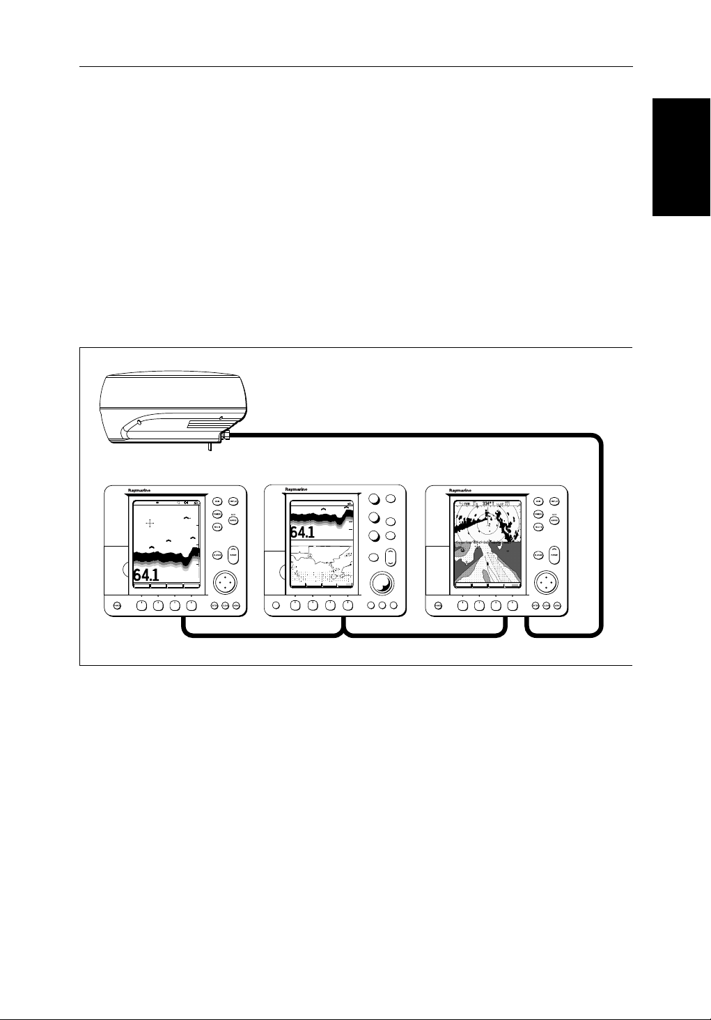
Chapter 1: Overview 1-5
masterdisplay)viathehsb2connectionandcanbedisplayedandcontrolle don
anyother
2
hsb
seriesLCDorCRT display(therepeaterdisplay).
Inparticular, you can connect your Radar to a remote Chartplotter(or
Fishfinder/Chartplotter)toprovidesimilarfunctionalityto thecombined
Radar/Chartplotter(or Fishfinder/Chartplotter).However,you should be
awarethatifyou change, say,radarrangeon one display, it affectsalldisplays
showingradar(orradar/char toverlay on color displays).
2
hsb
The
systemcaninclude severalchartplotterdisplays,eachwithtwo chart
cartridgeslots.Eachdispla ycan access two local and up to six remote chart
cartridges.Chartscanbe controlledindependentlyoneachdisplay ,evenwhen
aremotechartcartridgeisbeing used.
Pathfinder Scanner
PLUS Display Units
PLUS Display Units
hsb2 Fishfinder Display
AUTO GCRZFH
SD
50kHz
0
8
25
38
45
52
ft
ZOOMFREQUENCY
BTM.LOCK A-SCOPE
50
75
100
Fishfinder, Chart, Radar transferred to all displays
Figure 1-1:
hsb
PLUS Display Units
Features
• Chartplotter–Displayschartinfor mationfromtheC-MAPNT®chart
cards(C-Cards)
• UsespositiondatafromGPS,DGPS,WAAS or Loran-C technology
• Displaysandtransfers
• Providesfullcontrolofdatafromother
• Severalfull-scree noperating modesincluding:Radar, Chart, Data Log or
Sonar,ifappropriate data is available.
hsb2 Radar/Chart Display
AUTO G RZ
50kHz
0
200
ft
ZOOM MORE¬FREQUENCY CHRT SNR
POWER
2
Integrated System
2
hsb
,SeaTalk and NMEA data
GAIN
SEA
MULTI
ALARMS
ENTER CLEAR MENU
2
hsb
Radar Display
DISPLAY
MOB
MARKS
VRM/EBL
RANGE
GOTO MORE!ROUTE RDR CHRT
D5569-1
2
hsb
instruments
Page 20

1-6 hsb
2
PLUS Series Color LCD Display
Operating Modes
Operating Modes
• Viewradarandchartsimultaneouslyas radar/chart overlay or in half-
screenwindows.
• Half-screenwindowstodisplayadditional data: Course DeviationIndica-
tor(CDI),BearingandDistanceIndicator(BDI), navigation data.
• CursorechoacrossSeaTalk, and betweenchartandradarwindows
• Choiceoforientation:HeadUp,CourseUpandNorthUp
• ThesystemcanbeconnectedtoanST80Navigatorkeypad for entry of
alpha-numericdata.
Set Up Options
Setupoptionsallowyoutochoosewhatis displayed, how it is displayed
(includinglanguageandunits),bearing mode and how the display operates
withother
fromotherequipment,e.g.speed,heading, depth, wind and tide information
inasetofuser-selec tabledataboxes.Forsystemswithanautopilot,whenthe
statusandlockedheadinginformationchange the new data can be displayed.
Displayoptionsareprovidedin System Set Up, described in Chapter 7.
ScreenPresentationOptions,described in Chapter 2 allow you to switchthe
cursoranddataboxesOn/Off.The cursor box and user-selecteddataboxes
canbemovedaroundthescreen.
2
hsb
units.You can viewthecursorpositionandavarietyofdata
Operating Modes
Onasinglehsb2unityoucan view a fullscreenradarand, on a combinedunit,
youcanoverlaytheradartargetsontothefullscreenchart . Youcanalsoset
Win dowsOn to split the display into two half-screenwindowstoshow
supplementarydataor, on a combined display unit, display radar and chart
simultaneously. The main operating mode (radarorchart)isdisplayedinthe
upperwindow;youchoosewhatisdisplayedinthelowerwindow.
Thefollowingareavailable:
Table 1-1:
Display Full-screen mode Half-screen Window Options
RL70C PLUS,
RL80C PLUS
RC530 PLUS,
RC631 PLUS
RL70CRC PLUS,
RL80CRC PLUS
hsb
2
Single Display Operating Modes and Window Options
Radar CDI, BDI or Nav Data
Chart CDI, BDI or Nav Data
Data Log Windows not available
Radar Mode CDI, BDI, Chart or Nav Data
Chart Mode CDI, BDI, Radar or Nav Data
Radar/Chart Overlay
Data Log Mode
Windows not available
Page 21
Chapter 1: Overview 1-7
Radar Display Chartplotter Display
Operating Mode for
Stand Alone Units
RR
000°
0.220
1/2
HEAD UP
3nm
CURSOR
BRG
RNG nm
HDG MODE TARGETS SCREEN
IR
MARPA
Operating Modes
Operating Modes
Additional Modes for
Linked Units
(or combined
Radar/Chartplotter)
DISPLAY
TIME POSITION CMG DMG
DISPLAY
15:30
16:00
16:30
17:00
17:30
18:00
18:30
19:00
19:30
STOP LOG
50°21^890N
001°20^610W
50°18^010N
001°20^070W
50°21^850N
001°19^290W
50°18^500N
001°21^300W
50°20^990N
001°18^280W
50°19^660N
001°21^960W
50°19^730N
001°18^030W
50°20^930N
001°21^750W
50°18^550N
001°18^650W
CLEAR LOG
346°
180°H
012°H
206°H
043°H
245°H
093°H
302°H
145°H
H
Figure 1-2: Full Screen Operating Modes
6.86
7.23KM
7.23KM
6.67KM
5.74KM
5.00KM
4.63KM
5.00KM
5.74KM
KM
HSB
SeaTalk
RR
000°
0.220
1/2
50°21^890N
001°20^610W
50°18^010N
001°20^070W
50°21^850N
001°19^290W
50°18^500N
001°21^300W
50°20^990N
001°18^280W
50°19^660N
001°21^960W
50°19^730N
001°18^030W
50°20^930N
001°21^750W
50°18^550N
001°18^650W
CLEAR LOG
HEAD UP
346°
180°H
012°H
206°H
043°H
245°H
093°H
302°H
145°H
H
3nm
CURSOR
BRG
RNG nm
HDG MODE TARGETS SCREEN
TIME POSITION CMG DMG
15:30
16:00
16:30
17:00
17:30
18:00
18:30
19:00
19:30
STOP LOG
MARPA
6.86
7.23KM
7.23KM
6.67KM
5.74KM
5.00KM
4.63KM
5.00KM
5.74KM
IR
KM
D4285-1
Page 22

1-8 hsb
2
PLUS Series Color LCD Display
Operating Modes
Operating Modes
Half-Screen Window Options
• Chartdisplay, Radardisplay:Ifdataisavailableasafunctionof the
combineddisplayunititcanbe displayed full screen, as shown in
Figure 1-2, or in a half-screenwindow.
• CDI:ThisgivestheCourseDeviationIndica torgraphical display,with
datarelatingtothetar getwaypoint.
• BDI:This givestheBearingandDistanceIndicatorgraphicaldisplay,with
datarelatingtothetar getwaypoint.
• NavData:Thisshowssixteendataboxes,providing navigational data in
theunitsspecifiedinyoursetup. Note that up to 6 of these data boxes are
alsoavailableasauser-selectablegroup (seeSection 7.3).
You select the operatingmodeandwindowsusingtheDISPLAY keyas
describedinChapter 2.
Multi-display systems
Ifyouhaveseveralhsb2seriesRadarandChartplotterdisplays connected
operationissimilartoacombined Pathfinder Radar/ChartplotterUnit:four
full-screenmodes–radar, chart, radar/chartoverlay(colordisplaysonly) and
datalogareavailableonalldisplays.
Inaddition,ifyouhavean
setany displayto fishfindermode;ifthesystemincludesachartp lotter,similar
functionalitytoacombinedFishf inder/Chartplotter is availableonall
displays.
2
hsb
seriesFishfinderdispl ayconnected, you can
Onan
2
hsb
systemwithRadar ,Chart and Fishfinder available,thefollowing
informationcanbeshownonanydisplayunit:
Table 1-2: Window Options for Integrated Systems
Full-screen mode Half-screen Window Options
Chart Mode, CDI, BDI, Nav Data, Fishfinder or Radar
Radar Mode CDI, BDI, Chart or Nav Data
Fishfinder Mode Depth/temp, Chart or CDI, BDI
Radar/Chart Overlay Windows not available
Data Log Mode Windows not available
Fordetailsonthefishfinder, refer to the
2
hsb
SeriesDisplayOwner’s
Handbooksuppliedwithyourfishfinder.
Page 23

Chapter 1: Overview 1-9
Heading and Position Data
Fullfunctionalityoftheradar/ chartplotterisachievedwhenit ispartofan
integratedsystemwithotherequipment (in addition to another
connectedviaSeaTalk or NMEA 0183. Data from this equipmentincluding
positionandheadingisshownonthedisplay and is used in calculations.
Detailsonconnectingotherequip me ntare given in Chapter 8.
Providing Heading Data for Radar/Chart Overlay and MARPA
TheperformanceofMARPA and Radar/Chart Overlayisdependentonthe
qualityofyourheadingsensor.Itisimportantthatboththe headingsensorand
theradarscanner(bearingalignment) are correctlycalibrated.Refertothe
appropriateheadingsensorand radar scanner handbooks for calibration
details.Thebettertheaccura cyof your heading data, the betterthe
performanceofMARPA and Radar/ChartOverlay.
Agyrocompassprovidesthebestperformanceinallconditions.Alternatively
youcoulduseafluxgatecompasswithrategyro stabilization.
MARPA requires heading data to be frequentlyupdated(werecommenda
dataoutputrateofgreaterthan8Hz);headingdatamustthereforebeprovided
to the display on NMEA.
Inmultiple-displaysystems,heading must be connected, via NMEA, to each
displaythatwillbeusedforMARPA.
hsb
2
unit)
Data
Data
Heading and Position
Heading and Position
We recommend the Pathfinder SmartHeadingSystem(whichincludesthe
Gyro Plus 2 unit). Good results are also obtainedwith a Raymarine autopilot
systemincorporatinga 150G or 400G CourseComputerwithinternalrate
gyro.
Otherheadingsensorsconnectedon NMEAmay providesatisfactoryresults
inreasonablesea states.However, in unsettledconditio nsa rategyrocompass
isadvisable.
ContactRaymarineCustomerServicesor your authorized Raymarine dealer
foradditionalinformation.For specific configurationdetailswiththe
Raymarinecoursecomputerrefe rto Appendix E. If you are using a suitable
third party heading sensor, refer to its documentation for installation and
calibrationdetails.
Page 24

1-10 hsb
The Pathfinder Radar
The Pathfinder Radar
PLUS Display
PLUS Display
1.2 The Pathfinder Radar PLUS Display
2
PLUS Series Color LCD Display
Whenascannerisconnectedandtheradarisin Transmit mode,theradar
pictureprovidesamap-likerepresentation of the area inwhichtheradaris
operating.Typically,your ship’sposit ionis at the centreofthedisplay, and its
deadaheadbearingisindicatedbyaverticalheadingline,knownas theShip’s
Heading Marker (SHM).
Theradarpicturecanbeviewedwithavariet yof fixed or customised range
scales.Thecoloroftheradarretur ns(echoes) indicates theirintensity:the
strongestreturnsareshown in yellow and the weaker are shown in shades of
blue.Astatusbarat the top of theradarimagedisplaysrange, currentheading
andmodeindicatorsforthevarious options you can set.
Anexampleradarpictureisshownonthenextpage,withexampleradar
returns(echoes)anddefaultPathfinder Radar information.TheStatusBaris
alsoillustrated.
Theradardisplaycanshowadditionalinformation, depending on your
currentlyselectedoptions, set up selectionsandthedataavailablefromother
equipment.Theexampledisplayson the following pages show someofthese
features.
Functionsareavailableto control the display as follows:
• ZoomtheDisplay
• Offsetyourvesselfrom the centre of the radar picture
Operationofthesefunctionsis described in Chapter 2.
Pathfinder Radar PLUS Display Options
In additiontothedisplaysetup optionspreviouslydescribed,radar set up
optionsallowyoutocustomisethe radar image by selecting how radar marks
andElectronicBearingLine (EBL) data are displayed. You can also specify
timedtransmitmodeandcustomrangescales.
TheScreenPresentationOptions, describedinChapter 2 allow you to switch
rangeringson/offandwaypointdisplay on/off.
Note:Whenyouturnthedisplayoffand onagain,the ScreenPresentationsettingsareretainedinmemory.
Page 25
Chapter 1: Overview 1-11
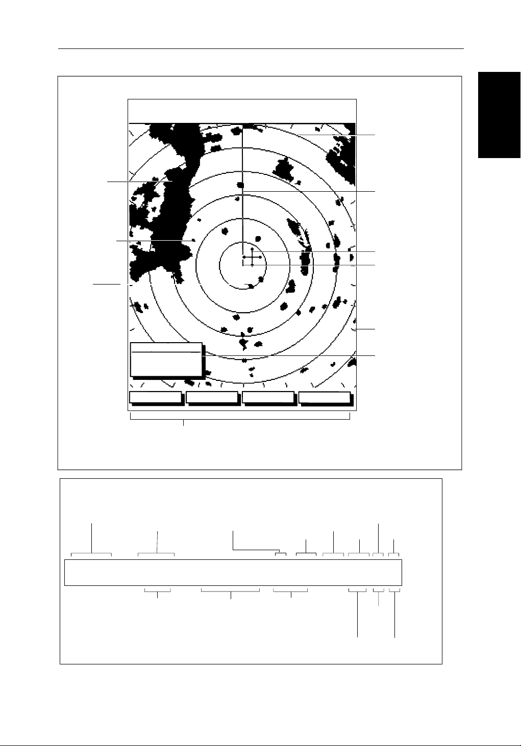
Default Display
Targets:
Landmass
Channel buoy
Surface
vessel
RM RV3
H-UP
AUTO
T
MARPA
IR
045°
0.28
RINGS
1/2
R
126°T
3nm
CURSOR
BRG
RNG nm
HDG MODE TARGETS SCREEN
Default soft key labels
These can be turned off; press any soft key to re-display them.
Different labels are displayed when you press a key.
Status Bar
Range rings
The number and
spacing depend on
the current range, or
you can turn them off
Ship's Heading
Marker (SHM)
You can hide this
temporarily
Cursor position,
controlled by the
trackpad
Ship's position
You can move this
off-centre if required
Bearing scale,
each tick indicating
o
2
of azimuth
Cursor position box
Shows the current
cursor position as
either Range/Bearing
or Lat/Long. You can
move this box to your
preferred position
on the screen, or
turn it off.
D3600-6
Pathfinder Radar
Pathfinder Radar
PLUS Display Options
PLUS Display Options
Status Bar
Selected range,
in nautical miles
3nm
Range rings
(displayed if
rings are on)
Motion Mode
Relative Motion
True Motion
RINGS
1/2
Range ring interval
Not displayed if
range rings are off
126°T
Current heading
if data available, or
Course Over Ground.
Displayed in degrees
Magnetic or True
Figure 1-3: Radar Display Features
displayed when function on:
Target Vectors
True Vector or
Relative Vector
and vector length
RM RV3
H-UP
Heading mode
Normally Head Up (H-UP);
Course Up (C-UP) or
North Up (N-UP) can be
selected if heading data
available
Auto mode
Gain, Sea,
Tune
AUTO
GST
(Remote rain)
Mode Indicators
Target
Expansion
Wakes
WKS
FTCEXRCGZIR
FTC
Guard Zone
Alarms
Rain
Clutter
Interference
Rejection
D3993-2
Page 26
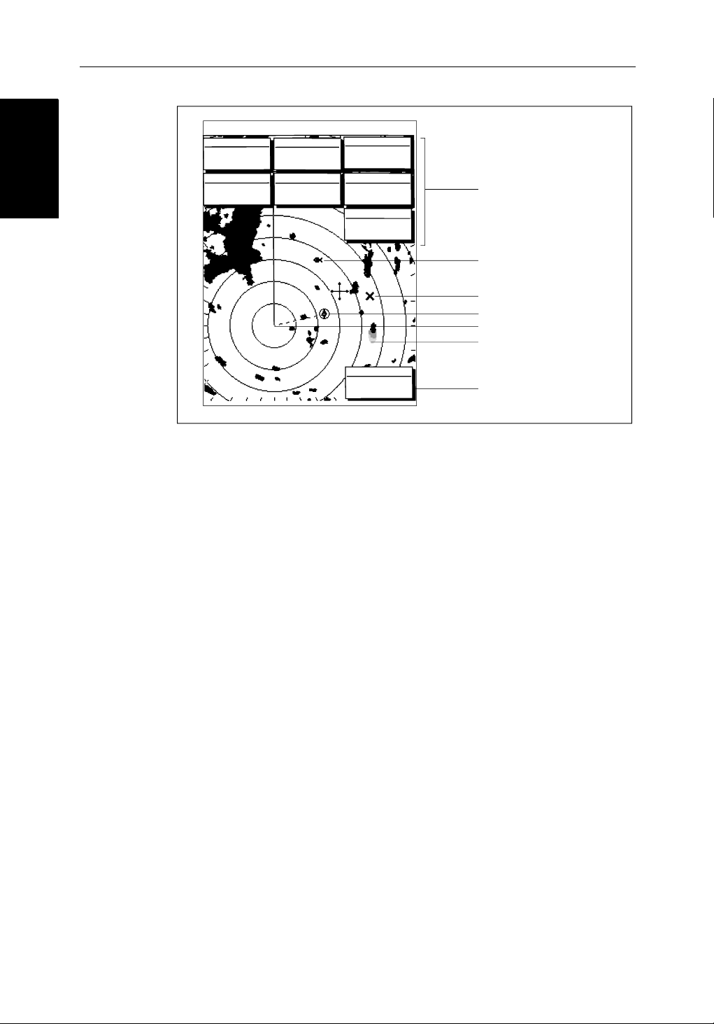
1-12 hsb
Radar Functions
Radar Functions
3nm
BRG
RNG
CURSOR
063°
1.65
COG
120@T
RR
1/2
R
50°49^13N
001°12^09W
nm
6.3kts
126°T
POSITION
SOG
AUTO
H-UP
GST
TIME
13:48:06
SPEED
5.7kts
DEPTH
FTC
FTC
14.4m
WPT
T 1.20nm
203°
01h:30m
Figure 1-4: Typical Radar Picture
2
PLUS Series Color LCD Display
EX
RC
IR
Data boxes, showing data
(if available) in the selected
units
Mark, symbol selected using
setup options
Mark, default symbol
Active waypoint - from Chartplotter
Offset centre
Long target wake (short,
medium or long wakes can
be selected)
Waypoint data box, showing
range, bearing and time to go
D3601-2
Radar Functions
Thehsb2(PLUS)seriesPathfinderRadarincludesthe following functions:
• Choiceofrangescalesfrom
• Automaticandmanualcontroloftuning,gain and sea clutter.
• TwoVariableRangeMarkers(VRMs)andElectronicBearingLines
(EBLs),allowingtargetrange and bearing measurements.
VRM/EBLs canbe floated.
• Targetwakesand target expansion mode.
• Twoguardzoneswithalarms.
• Addmarkstorecordimportantordangerouslocations.
• ManOverboard(MOB)tonavigatebacktoa personorobject.
•10TargetMARPA
Operationoftheseradarfuncti onsis described in Chapter 3 and Chapter 4.
1
/8nm to 72nm(dependentonscannertype).
Page 27

Chapter 1: Overview 1-13
1.3 The Chartplotter Display
The PLUS seriesdisplaycanincludesaChartplot ter .The chartplotter
includesasmall-scaleworld map and detailed navigationinformationis
displayedwhenacartographicchart card is installed. The detailsdisplayed
dependonthechartzoom level selected.Aplottermodeis provided toenable
routeplottingandtrackingat large scales evenwhenachartcardisnot
installed,orwhenthechartiszoomedbeyond the available cartographic
detail.AtypicalchartplotterscreenisshowninFigure 1-5.
Thechartplotterusespositioninformation from a GPS, DGPS, WAASor
Loran-Cinstrument.Once the position fixhasbeenestablished,your vessel’s
position,ifonscreen,isshown as a boat shape pointing in the direction of the
currentheading(orCOGifheadingdatais not available). If no heading or
COG dataisavailable,thevesselis shown as a circle.
Thechartplotterscreenincludes a status bar that displayschartscale,with
eithercursorposition,range and bearing or,whenthecursorishomedtothe
vessel(bypressingFIND SHIP),vesselposit ion,Speed Over Ground (SOG),
CourseOverGround(COG)andfixtype(VESPOS,DIFFIXorSD FIX).
Thestatusbaralsoindicatesif radar/chart overlayisswitchedon.
The Chartplotter
The Chartplotter
Display
Display
Anywaypointsyouhaveplacedaredisplayed(unless you turned them offin
ChartSetUpasdescribedinChapter 7) and the current routeis shown.
Informationcanbeviewedon-screenby positioning the cursor over a
waypoint,currentrouteor chart object. The chartplotterscreencanalsoshow
additionalinformation,depending on your currently selectedoptions,setup
selectionsanddataavailablefrom other equipment.
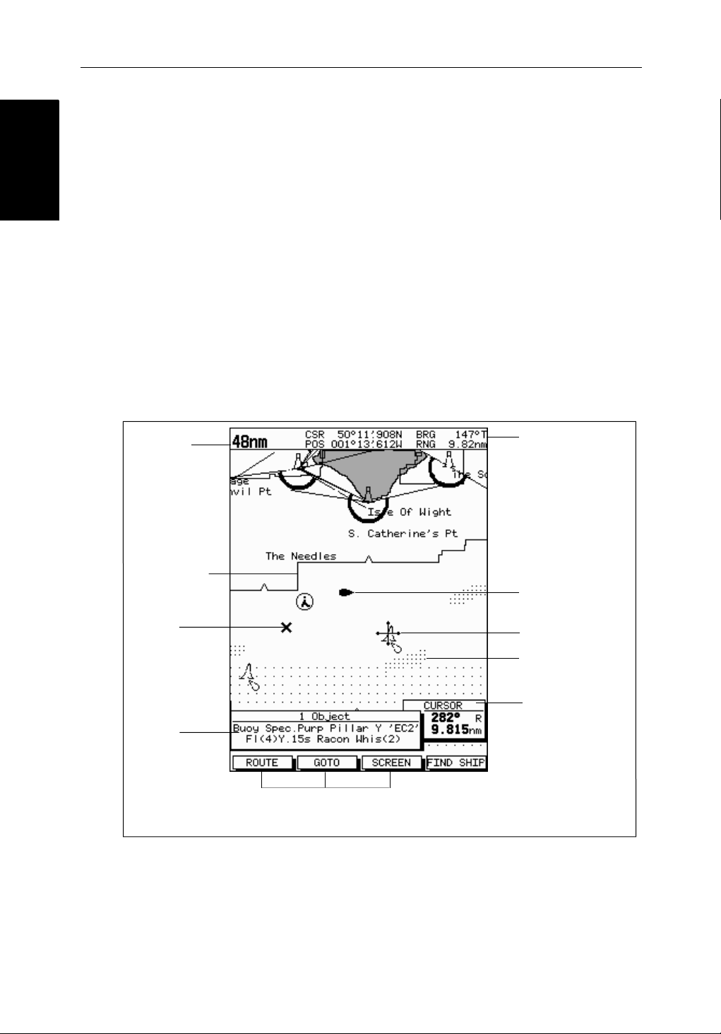
Anexamplechartdisplay, in its default configuration,withachartcard
installed,isshowninthefollowing illustration.
Severalfunctionsareavailabletocontrolthedisplayasfollows:
• Zoomin/outandPantheDisplay
• OffsettheChartorCentertheChartaroundtheVessel
• OverlayRadarTargets onto theChart Display
• SynchronizetheChartandRadar(if radar data is available)
Operationofthesefunctionsis described in Chapter 2.
Page 28
Chartplotter Display
Chartplotter Display
Options
Options
1-14 hsb
Chartplotter Display Options
Inadditiontothedisplaysetup options previously described,chartsetup
options,describedinChapter 7,allowyouto customizethechartbyselecting:
• Whatcartographicfeatur esand level of detail are displayed.
• Thechartcolorpalette(sunlightor shade).
• Chart orientation (north up, head up orcourseup),datumsandpositionoffset.
• Howwaypointsaredisplayed(symbolsandnumbers)and the availability
ofchartobjectidentificationdata.
• Vectors forheading,COGandtide.
TheScreenPresentationOptions, describedinChapter 2 allow you to switch
theChartGridOn/OffandCustom Chart Details On/Off.
Note:Whenyouturnthedisplayoffand onagain,the ScreenPresentationsettingsareretainedinmemory.
2
PLUS Series Color LCD Display
Chart Range
Chart Boundary
Waypoint
Object data box -
for object selected
by cursor
Figure 1-5: Typical Chartplotter Display
Status Bar
Default soft key labels
These can be turned off: press any soft key to redisplay them.
Different labels are displayed when you press a key.
Vessel Position
Cursor -
selecting chart object
Depth Area
Cursor position box
Shows the current
cursor position as
either Range/Bearing
or Lat/Long. You can
move this box to your
preferred position on
the screen or turn it off.
D4275-2
Custom Chart Details
Thechartplottersetupoptionsinclude a sub-menu to customize the
cartographicfeatures .This menu allows you to switch featuresOn,Off,or
controlthemusingtheCUSTOM softkey. The factory defaultsettingsforthe
Customchartoptionsareasfollows:
Page 29

Chapter 1: Overview 1-15
ON: Charttext,chartboundaries,depthcontours, navigation marks
andlandfeatures.
OFF: Cautionandroutingdata.
CUSTOM: Spot sounding, lightsectors,marinefeatures.
Note:Thefactorydefaultforthe CUSTOM settings is ON.
Iconsaredisplayedindetail,depth shading limit is 10 m and depthcontour
displayis0-100m.
Acompletelistofchartfeaturesisgivenin Appendix C.
Chartplotter Functions
TheChartplotterincludesthe following functions:
• DisplayC-MAPNTC-CardchartinformationincludingPortsandTides
(ifavailable)
• View chart information (if available) for the Nearest Port
• Place,Move,EraseandEditaWaypoint
• GotoWaypoint or Cursor
• Create,Save,Name,EditandFollowaRoute
Functions
Functions
Chartplotter
Chartplotter
• ReviewRouteandWaypoint Lists
• Displayvessel’s track; Save and Name the Trackforre-calltoscreen
• SmartRoutetomakeatrackintoaroute
• MeasureChartDistancesandBearingson-screen
• SetUpAlarmsandTimers
• ManOverBoard(MOB)tonavigatebacktoamissingpersonor object
• DifferentialGPS set up page
Operationofthesefunctionsis described in Chapter 5 and Chapter 6.
Page 30
1-16 hsb
Operating Controls
Operating Controls
1.4 Operating Controls
You operate the radarandchartusingavarietyofcontrols:
• A trackpadprovidingup,down,left,rightanddiagonalcontrol of an onscreen cursor.
• Elevendedicated(labeled)control keys.
• Foursoftkeyswithlabelsdisplayedonthescreen.
• Pop-upmenus,displayedon-screen, from which you select options.
• Databaselists,displa yedon-screen, which enableyoutoedititems.
Note:Thecursoristhecross-hairsymbol (+) visible on thedisplay.Youmove
thecursorusingthetrackpadand use it to selectapositionoritemonthechart.
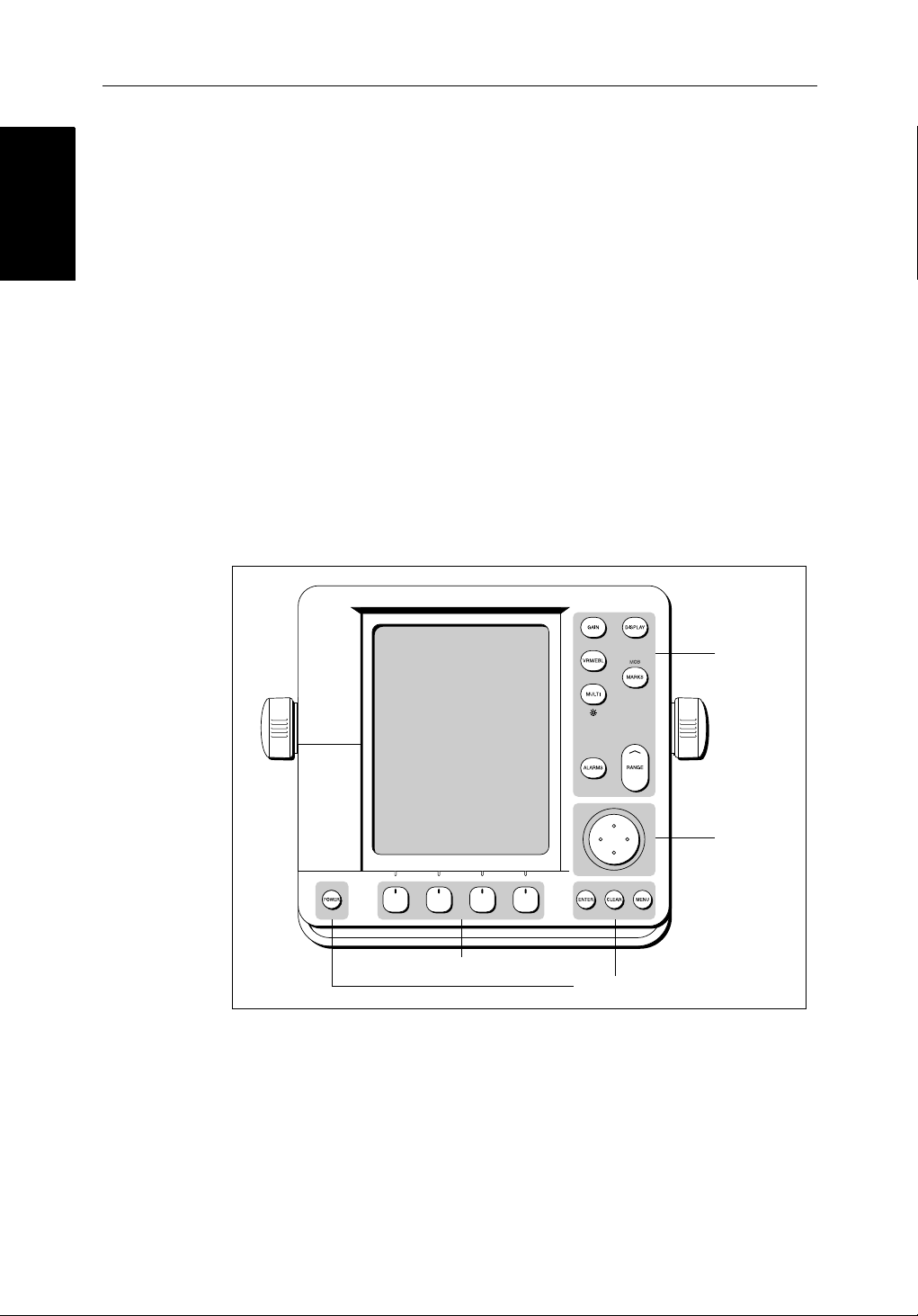
Thecontr olkeysare showninFigure 1-6.Theyareback-litfornight-timeuse.
Whenyouuseacontrol,ahelpmessageisdisplayed at the top of the screen
(unlessyouswitchhelpoffas described in Chapter 7). The following
paragraphsdescribethecontr olsand on-screen facilities.
2
PLUS Series Color LCD Display
Figure 1-6: LCD Display Control Keys
Trackpad and Cursor
Thetrackpadhasseveralfuncti ons:
• Tomovethecursoraroundthescreen
Soft keys
Dedicated keys
Dedicated
keys
Trackpad
D3596-3
• Toselectanitemfromapop-upmenu
• Toadjustavariablesoftkey control
Page 31

Chapter 1: Overview 1-17
Thecursorisusedto:
• Selectapositiononthescreen.
• Selectanitem,e.g.guard zone on the radar,chartobject on the chartplotter.
• Selectanareaoftheradarimagetozoomintoorpan the chart display..
Moving the Cursor
You can pressonanyofthe four sectionsofthetrackpadto move the cursorin
thatdirection(up,down,leftorright),orpresstwosectionsatthesametime to
movediagonally. The cursor moves faster as you continue topressthe
trackpad.Thecurrentcursorposition is shown in the cursor data box (if
selected).
Thecursorisnormallydisplayedas acrosshair. However, if you havenot
movedthecursorformorethanfiveseconds,whenyounext moveitthecursor
isoutlinedbyacirclesoitis easier to locate on the screen.
Note:Duringmanyoperationsyoucannotmovethecursoraroundthe
screen;ifyoucannotmovethecursorusingthetrackpad,checkthedefaultsoft
keysaredisplayed(unlesstheyhave been switched OFF in system set up). If
not,pressENTER until they are displayed.
Trackpad and Cursor
Trackpad and Cursor
Context-Sensitive Cursor Control
Thecursoriscontext-sensitive .When the cursor is positioned over special
featuresonthe display atextlabelappears to identifythefeat ureas detailedin
Table 1-3 .
Moving and deleting items with the context-sensitive cursor
Someitemsontheradar/chartplotterscreenhaveinformation associatedwith
them.Mostinformationisdisplayedin a data box. The context-sensitive
cursorallowsyoutomovedataboxes.It also allows you to move or delete
otheritems,suchasradarguardzones.Further details of items thatcanbe
movedordeletedaregivenintheappropriate sections throughout this
handbook.
➤ Tomoveanydataboxorselect able item:
1. Usethetrackpad topositionthecursorover theitemuntil theitem’s labelis
displayed.
2. PressENTER totake control of the item, use the trackpad tomoveittothe
requiredposition.
3. PressENTER aga into fix the position, or press CLEAR toabandonthe
move.
➤ Todeletean item:
1. Usethetrackpad topositionthecursorover theitemuntil theitem’s labelis
displayedthenpressCLEAR.
Page 32

1-18 hsb
Dedicated Keys
Dedicated Keys
Table 1-3: Context-Sensitive Cursor Text Labels
Text Label Feature Radar/Chart
BOX Data box (any type) Both
MOB Man Over Board marker Both
MRK Radar Mark Both
WPT Chart Waypoint Both
CTR Center of radar Radar
FLT Floating EBL/VRM Radar
GRD Guard zone Radar
MARPA MARPA Target Radar
SHM Ships Heading Marker Radar
VRM/EBL VRM and EBL, 1 or 2 Radar
ZMB Zoom box Radar
2
PLUS Series Color LCD Display
A
➟B
COG Course Over Ground vector Chart
HDG Heading vector Chart
POS Vessel’s position Chart
RTE Route leg Chart
TIDE Tide vector Chart
Dedicated Keys
The dedicated keys: DISPLAY, MARKS, GAIN, VRM/EBL, MULTI,
ALARMS, RANGE, ENTER, CLEAR, MENU andPOWER havefixed
functions;thefunctionsare similar on all Pathfinder displays.Forexample,
ALARMS is usedtoset upthesystemalarms onbothachartplotterandaradar.
Somekeyscanbeusedintwoways:
• Press:Pressthekeymomentarilyandthenreleaseit. This method is used
formostkeyoperations.
• Pressandhold:Pressthekeyand holditdownforthelengthoftimestated
(forexample,3seconds),andthen release it.
Whenyoupressadedicatedkey, one of the following happens:
Ruler line Chart
i. The associated operation isactioned,e.g.changechartscale(RANGE).
ii. Apop-upmenu is displayed, providing furtheroptions.
iii. A set of soft keys is displayed, providingfurtherfunctions.
Page 33

Chapter 1: Overview 1-19
Asyoupressakey, a singleaudiobeepconfirmsthekeyaction.If the keypressisnotvalidforthecurrentscreen or mode, three rapid beeps sound to
indicatethatnoresponseisavailable. If required, you can turnthekeybeeps
offaspartofyoursetupprocedure(see Chapter 7).
Soft Keys
Thefourkeysbelowthescreenarecalledsoft keys because their functions
changeaccordingtotheoperation.Thesoftkeysaregroupedintorelatedsets
andsubsetsprovidingaccessto the various functions. The soft keylabelsare
displayedonthescreenjustabovethekeys.Thedefaultsoftkeysaredisplayed
untilyoupressakey, or select an item on the screen;thesoftkeysassociated
withtheactionarethendisplayed.
Thecurrentlyselectedsoftkey optionisshown byitsgreenbackground.Ifthe
keytextisdisplayedingrayratherthan in black, it is not currentlyavailable.
Whenyoupressasoftkeyoneofthefollowinghappens:
i. The associated operationisactioned,e.g.NORTH UP.
ii. Asub-setof soft keys is displayed, providingfurtherfunctions.
iii. A pop-up menu is displayed, providingfurtheroptions.
Aswithdedicatedkeys,whenyoupressa soft key a single audio beep
confirmsthekeyaction.Ifthe key-press is not valid for the currentscreenor
mode,threerapidbeepssoundtoindicatethat no response is available.If
required,youcanturnthekeybeepsoff as part of your set up procedure (see
Chapter 7).
Pop-Up Menus
Pop-upmenususuallyprovidesetupoptions.When a pop-upmenuisonscreen, a set of associated soft keys is also displayed as shown in Figure 1-7.
You use the trackpadtoselectanoptionfromthemenu,thenusethe
appropriatesoftkeytosettheoption. For example, you can toggle the OFF
TRACK ALARM on/off.
TARGETS SCREENHDG MODE
RDR CHRT
D4152-2
Page 34

1-20 hsb
ALARMS SET UP
2
PLUS Series Color LCD Display
ARRIVAL ALARM
OFF TRACK ALARM
ANCHOR ALARM
GROUNDING ALARM
COUNTDOWN TIMER
ALARM CLOCK
Figure 1-7: Typical Pop-up Menu
Database Lists
Thewaypoints,routesand tracks that youcreateonthechartplot terare stored
indatabaselists.Youcanviewtheselistsandselec titems for editing.
0.01nm
ON
OFF
5M/1.0nm
00:33:00
OFF
SELECT ARRIVAL
ALARM RADIUS
D4265-4
WAYPOINT LIST
SYMBOL NAME
WAYPOINT 001
WAYPOINT 002
WAYPOINT 003
WAYPOINT 004
WAYPOINT 005
POSITION
BRG _186°
TEMP
---°
DATE
GOTO
WAYPOINT
--/--/--
EDIT
WAYPOINT
Figure 1-8: Typical Database List
Aswithpop-upmenus,whenadatabaselistison-scre en,a set of associated
softkeysisalso displayed;youusethetrackpadto select anitemfromthelist,
thenusetheappropriatesoftkeytoedit theitem.Forexample,you canerasea
waypointoraroute.
50°21^966N
001°20^368W
RNG _21.0nm
C
DEPTH
TIME
MAKE NEW
WAYPOINT
m
---
--:--:--
WAYPOINT
TRANSFER
D4262-2
Page 35

Chapter 2: Getting Started & Adjusting the Display 2-1
Chapter 2: Getting Started & Adjusting the
Display
2.1 Introduction
Thischapterprovidesinformationand instructions to get you started using
yourdisplay. It will help you to become familiarwiththedisplayandthe
functionsofthecontrolsbefore you start using the unit. Moredetailed
informationonoperatin gthe radar display is providedinChapter 3and
Chapter 4. Chartplotter operatingdetailsaregiveninChapter 5 and
Chapter 6.
Conventions Used
Throughoutthishandbook,thededicated(labelled) keys are shown in bold
capitals;forexample,MENU.The soft key functions, menu namesand
optionsareshowninnormalcapitals;forexample, SCREEN.
Operatingprocedures,whichmay consist of a single key-press or a sequence
ofnumberedsteps,areindicatedby a➤ symbol inthemargin.
Whentheprocedurerequiresyou topressasoftkey ,thesoftkey iconisshown
in the margin.
Introduction
Simulator
Thedisplayunitincludesasimulatorfunction, that allows you to practice
operatingyourradarorChartplotterwithoutdatafromthescannerorGPS
system.You will needtousethesetupoptionstoswitchthedisplay to
simulatormode,asdescribedin Section 2.2. Youcan use it in either of two
ways:
• Beforethedisplayunithasbeeninstalled on your vessel. In thiscase,you
• Afterthedisplayhas been installedonyourvessel,but while inthemarina
Thefollowingsection,Section 2.2, includesinstructionstoviewsimulated
radarandchartimages.
onlyneedtoconnectthedisplaytoa12Vor24V DC powersupply, connectingtheredcorefromthepowerleadtopositive(+)andtheblack core
tonegative(-).SeeChapter 8 forfulldetails.
oratanchor.
Page 36

2-2 hsb
2
PLUS Series Color LCD Display
2.2 Switching the Display On and Off
IfyouhaveacombinedRadar/Chartplott er, the factory defaultpower-up
Switching the Display
On and Off
modeisradar.Onceyouhaveusedthedisplayunititpowers-upinthelastused
mode.Thefollowingsectionsdescribethe power-up sequenceinradarand
chartmodes,howtoadjustthelighti ngand how to select simulator mode.
Radar Mode
Thissectionexplainshowtoswitch the radar display and scanner onandoff,
andhowtoswitchthescannerbetweenTransmit,StandbyandScannerOff
mode.
Younormallyoperateyourradarintransmitmode,but youcanusethe display
unitwithoutthescanneroperatingas follows:
Standbymode: Youshoulduse this mode when you are not operating the
radarforshorttimeperiods.The scannerdoesnottransmitandtheantenna
doesnotrotate,sotheradaruseslesspower. However,thescannerremains
poweredsowhen youreturntotransmitmode,themagnetrondoes notneedto
warmup.
Scanneroffmode:You should use thismodewhenyoudonotrequirethe
radar,but youareusingthe displayunitsay,forchartdata ortoviewdatafrom
anothersource.Scannerof fmode removes power from the scanner.
➤ Toswitchthedisplay on, press and hold the POWER key until the unit beeps.
IftheunitwaslastusedinRadar mode,thekeys lightup,thedisplayshows the
Pathfindergraphic,followedbythestart-upinformationillustratedbelow,and
the radar starts themagnetron warm-up sequence.
WARMING UP
Figure 2-1: Switching on the Radar Display
Page 37

Chapter 2: Getting Started & Adjusting the Display 2-3
After70seconds,whenthemagnetronwarm-upsequenceis complete, the
Standbyscreenisdispl ayed,with the text STANDBY and a prompt to press the
POWER keytoenterTransmit mode.
➤ Toswitchtheradar scanner from Stand-bymodetoTransmitmode,press the
POWER key.
Thescannertransmitspulsedenergy while it rotates, and the antenna sweep
buildsuptheradarpictureusingechoes returned from targets.
On and Off
Switching the Display
Figure 2-2: Radar Transmit Mode
➤ Youcan switchonandadjustthedisplaybacklighting asdescribedlaterinthis
chapter.
➤ ToswitchtoS tand-bymode,press the POWER key.
ThedisplayreturnstotheSt and-byscreen,andthescannertransmis sionand
rotationstops.
➤ TouseScanneroff mode:
1. EnsurethattheradarisinStandbymode, warming up, or (if the unit is a
Repeater)displayingamessagethat radar data is not available.
2. PresstheCLEAR key.The messageSTANDBY. RADAR DATA NOT AVAILABLE
appearsintheradar picture.Thescanneris powered down andthetimer ,if
running,iscleared.
T oreturn to radar operation, press the POWER key. The warm-up countdown
isdisplayedandtheradargoesinto Standbymode.YoupressPOWER again to
switch to Transmit mode when required.
Page 38

2-4 hsb
2
PLUS Series Color LCD Display
Chart Mode
➤ Toswitchthedisplay on, press and hold the POWER k eyuntil the unit beeps.
Switching the Display
On and Off
Ifthedisplaywaslastusedinchartplottermode,thekeyslightupandthe
Raychartgraphicisdisplayed,followed by the caution:
CAUTION:
Raychartchartdisplaysarebased on cartographic data that
C-MAPbelievestobeaccurate.However,youshouldnotrelyonthese
displaysasyourprimarysourceofnavigation. Rather,your Raychart
shouldbeusedonlyasabackuptoofficialgovernmentchartsand
traditionalmethodsofnavigation.
Whenyouhave readandunderstoodthecaution,pressthe CONTINUE softkey.
The chart is displayed.
Ifthisisthefirsttimethechartplotter has been turnedon, andnochartcardis
installed,thedisplayshows the small-scale world map and the defaultsoft
keys.Otherwise,thedisplayshows the selected chart area and any datathat
weredisplayedwhenthedisplaywas last used.
Until unit beeps
D4277-2
Figure 2-3: Switch On - Chart Mode
Switch Off
CAUTION:
To provideprotectionagainstthedamagingeffects of UV light, it is
advisabletoreplacethesuncoverprovidedwhenthecolorLCDdisplayis
notinuse.
AreminderisdisplayedwhenyouswitchoffthecolorLCDdisplay.
➤ Toswitchthe scanner and displayunitoff,pressandholdthe POWER keyfor
threeseconds.Acountdowntimerisdisplay edas shown below:
Page 39

Chapter 2: Getting Started & Adjusting the Display 2-5
GAIN
DISPLAY
VRM/EBL
MARKS
MULTI
Countdown timer:
number of seconds
to power off
POWER OFF IN
3s
ALARMS
RANGE
Simulator Mode
Figure 2-4: Switch Off
Whenthecounterreacheszeroabeepsounds,and the display unit switches
off.ReleasethePOWER key.
Note:Switchthedisplayunitoffbeforeyouremovethepowercord.
Note:YoudonotneedtochangetoStandbymodebeforeturningoff the dis-
play:ifyou turn theradardisplayoff whileitisinTransmit mode,thescanner
isalsode-activated.
Simulator Mode
Whensimulatormodeisonasimulatordataboxisdisplayed.
Whenthedisplayisswitchedoffthenon again,simulatormodeismaintai ned.
ItisrecommendedthatyouselecttheSystem Set Up Menu and switch off
simulatormodewhenyouhavefinished.
MENU
SYSTEM
SET UP¬
➤ Toviewasimulatedimage:
1. PressMENU followed by the SYSTEM SET UP soft key.
Thesetupmenupop-upisdisplayed.
3
SECONDS
POWER
ENTER CLEAR MENU
D3599-1
2. UsethetrackpadtomovetheselectionbarovertheoptionSIMULATOR.The
simulatorsoftkeysaredisplayed.
3. In thesystemsetupmenu,pressRADAR t oview a simulated radar image,
DATA toviewthechart display with simulated position,orBOTH to view
simulatedradarandchartdata.
4. PressENTER twi ceto return to the default display.
Note:Anywaypointsplacedonthechartplotterin simulator mode are retainedinthedatabaselistandareavailableforuseinroutes.
Page 40

Brightness
2-6 hsb
Changing the Brightness
TheMULTI k eyon the color LCD display is used to adjustbrightness.The
brightnessofthescreencanbeadjustedover a wide range, suitable for
Changing the
viewingindaylight(highbright nesslevel) or at night (low brightnesslevel).
Thekeylightingisautomaticallyadjusted as you alter the screen lighting,so
thatyoucanalwaysfindthekeys.Ifyousetthebacklight to a high level, the
keylightingisdimmed; if yousetthebacklightto a low level,thekeylighti ng
levelisincreased.
Adjusting the Brightness
➤ Tochangethe screen brightness:
1. PresstheMULTI keytodisplaythesoftkeycontrols(Radar modesoftkeys
are illustrated):
ON
25%
75%
2
PLUS Series Color LCD Display
A
U
T
O
MULTI
ALARM
LIGHT
TUNE
D5036_1
2. The LIGHT softkeyindicatesthebrightnesslevel,usethetrackpad (up or
down)toincreaseor decreasethesetting.Youcan pressandholdthetrackpadtochangethesettingmorerapidly. The brightnesslevelisadjustedas
youchangethesetting.
3. PressENTER toreturn to the default screen,withthenewbrightnesslevel.
➤ Tosetthescree nbrightness to 100%:
PressandholdtheMULTI keyforonesecond.The brightness is increased to
100%.
Thebrightnesslevelisretainedwhenyou switch off the display.
Note:Duringnight-timeuse,thebrightnessmay be set very low, when subsequentlyoperatedduringthedayitmay notbeapparentthatthedisplayison;
pressMULTI, followedbythesecondsoftkeyfromtheleft, then use the track-
padtoincreasebrightness.Alter natively,pressandholdMULTI foronesec-
ondtosetthebrightnessto100%.
Page 41

Chapter 2: Getting Started & Adjusting the Display 2-7
2.3 Controlling the Display
You controlthe displayusingthecursorandcontrolkeys.Youstart all
operationsfromthedefaultscreen, that is the default softkeysaredisplayed:
Chart
GOTO SCREENROUTE FIND SHIP
D4160-1
Radar
Display
Controlling the
TARGETS SCREENHDG MODE
Whenyouhavecompletedanactionusingthesoft keys, press ENTER or
CLEAR toreturntothedefaultscreen;youmayneedtopressENTER or
CLEAR severaltimestoback-trackthroughthesoftkeyhierarchy.
Note:Ifyouhavesetupyoursystemsothatthedefaultsoft keys are not displayedallthetime,pressanysoftkeyto display the labels.
Theremainderofthissectiondescribeshowtoselectthemodeofoperation
andswitchhalf-screenwindowson/off. The following sections describehow
tosetupthedisplayfortheRadarandfortheChart.
Thecontrolsaresummarizedinthefold-outillustrationonpages2-1 1
and2-12.
Selecting the Mode of Operation
You use the DISPLAY keytoselectthefull-screenmode.
Ifthedataisavailableonyoursystem,the following modes (describedon
OperatingModesonpage 1-6) can be selected:
•Radar
• ChartandRadar/ChartOverlay
MARPA
D4152-3
•Datalog
TheDISPLAY keyalsoaccessesthesoftkeysfor the half-screen window
options.
2
hsb
Note:Ifyour
displaysystemincludesaFishfinderdisplay,refertothe
Owner’sHandbooksuppliedwithyourFishfin derfor operating details.
Page 42

Selecting the Mode of
Operation
2-8 hsb
➤ Tochangethemode,presstheDISPLAY keytoshowtheDISPLAY pop-up,then
DISPLAY
pressagaintocyclethroughthemodesavailable, shown in the Figure 2-5.
2
PLUS Series Color LCD Display
Figure 2-5: Using the DISPLAY Key
Theselectedmodeisshownbyaniconwitharedborderand the mode is
displayedonthe screen. Theassociatedhalf- screenwindowsoftkeys arealso
displayed.
Whentherequiredmodeisshown,pressENTER or CLEAR. The default soft
keysaredisplayed.Theselectedmode is shown full-screen; in Radar and
Chartmodeyoucanswitchonhalf-screenwindows for additional display,as
describedinthefollowingsection.
Ifyoupress DISPLAY again,thepop-upand softkeysforthe currentmodeare
shown.
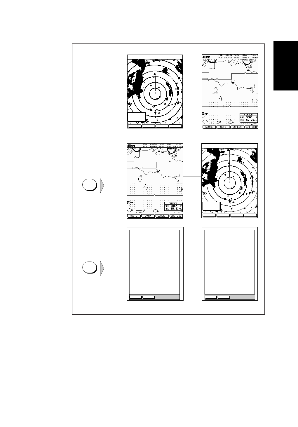
Selecting a Half-Screen Window for Display
Note:WindowscanonlybeusedwithRadarorChartscreens,theyarenot
availableonthedatalogscreen .
➤ Toselecta window for display:
1. From the full-screenRadarorChartmode,pressthe DISPLAY key .The
followingsoftaredisplayedwithan image of each available window:
Page 43

Chapter 2: Getting Started & Adjusting the Display 2-9
Radar:
DISPLAY
WINDOWS
OFF ON
SELECT
WINDOWS
ZOOM...
D4208-2
Chart
DISPLAY
WINDOWS
OFF ON
SELECT
WINDOWS
OVERLAY
OFF ON
D5708_1
2. Toselect a differentwindow, press either SELECT WINDOWS softkeyuntil
therequiredwindowis highlighted.Ifneces sary, this will toggle windows
on.PressENTER.
3. Totoggle windows off,presstheWINDOWS OFF ON soft key.
Figure 2-6 shows the half-screenhorizontalwindows(in radar mode).
Switching Control Between Radar & Chart Screens
Inacombinedoranintegratedsystem,toswitchcontrolbetween radar and
chart,youcanchangethefull-screenmodeusingtheDISPLAY key.
Alternatively, when you have both radar and chartdisplayedinhalf-screen
windowsthesoftkey RDR CHRT letsyoutoggle operatingcontrolbetween the
radarandthechartwindow.
Operation
Selecting the Mode of
DISPLAY
Ifawindowisactive,i.e.controlof the cursor via the trackpad is availablein
thatwindow,andyouswitchwindowsoff,controlautomaticallyreturnstothe
full-screen(upperwindow)mode.
Radar:
TARGETS MORE¬HDG MODE
RDR CHRT
D5668_1
Chart:
GOTO MORE¬ROUTE
RDR CHRT
D4168-1
➤ Tochangethe active window,pressthe RDR CHRT softkeytotogglecontr ol
betweentheradarandchartdisplay. The currentactivedisplayishighli ghted
in red on the RDR CHRT labeland the cursor appears in that window .
Returning to the Full-Screen Display
To returntothefull-screendisplay you can turn windows off,aspreviously
described.Alternatively, toreturntofull-screendisplay:
➤ Press and hold the DISPLAY key for2secondstoreturntothecurrently
selectedfull-scree n(upper window) display
Page 44

2-10 hsb
2
PLUS Series Color LCD Display
Selecting the Mode of
Operation
CDI Window
WINDOWS
OFF ON
SELECT
WINDOW
ZOOM
OFF ON
BDI Window
WINDOWS
OFF ON
SELECT
WINDOW
ZOOM
OFF ON
Navdata Window Chart Window
WINDOWS
OFF ON
SELECT
WINDOW
ZOOM
OFF ON
WINDOWS
OFF ON
Figure 2-6: Radar Half-Screen Window Options
SELECT
WINDOW
RDR CHRT
ZOOM
OFF ON
D4150-1
Page 45

Chapter 2: Getting Started 2-11
GAIN
Controls the presentation of radar targets.
GAIN controls background noise (speckle).
SEA controls sea clutter.
RAIN controls rain clutter around the vessel.
FTC controls rain clutter at a distance.
- Press for soft keys display.
MANUAL MANUAL
O
F
F
RAIN SEA
75%
50%
GAIN
FTC
O
F
F
Select a slider using the soft key or trackpad.
Toggle between Auto/Man or off/on by pressing soft key again.
Adjust slider using trackpad, and press ENTER to finish.
VRM/EBL
Used to measure range and bearing to/between targets.
- Press to place VRM/EBL if one not already placed.
Adjust position using trackpad, and press ENTER to finish.
- Press to display soft keys if VRM/EBL already placed.
VRM/EBL1
OFF ON
VRM/EBL2
OFF ON
FLOAT¬
VRM/EBL
DATABOX
OFF ON
Use soft key to toggle VRM/EBL on or off.
Press FLOAT to access float options for existing VRM/EBL.
Press VRM/EBL DATABOX to toggle data box display off/on.
MULTI
Controls guard zone alarm sensitivity, and tuning the receiver.
Also controls display lighting and brightness.
- Press to display sliders.
Press and hold MULTI key to set brightness to 100%.
ON
25%
ALARM
75%
LIGHT
A
U
T
O
TUNE
Select a slider using the soft key or trackpad.
Toggle between Auto/Man or off/on by pressing key again.
Adjust slider using trackpad, and press ENTER to finish.
Soft Key Labels:
Change when you press a key.
Default soft key labels are shown.
MARPASCREENTARGETSHDG MODE
Soft keys
Press to select option, or highlight option or slider.
Labels change when you press soft/dedicated key.
Elipses (...) after the text indicate that pressing soft
key leads to a further display of soft key options.
ENTER
Confirms selection and (if appropriate) clears current
soft key labels. It performs the selected task,
accepts changes, or leads to display of more options.
When cursor text is displayed, takes cursor control
of the object.
When arrow-head cursor symbol is displayed, drops
the object under cursor control.
CLEAR
Cancels operation in progress and returns to the
previous display.
Deletes an object/function under cursor control.
Trackpad
Controls cursor position on the screen, and also the sliders
and setup options.
Hold the trackpad down to move the cursor faster.
DISPLAY
Controls display mode and windows.
- Press for display mode and soft keys display.
- Press again to toggle through display modes, and ENTER
- Press and hold for 2 seconds for full screen display of the upper
window.
WINDOWS
OFF ON
SELECT
WINDOW
ZOOM...
Press soft key to toggle window on/off, or return to full screen.
Zoom: Press ZOOM key to display zoom window option.
Move Zoom box using trackpad, press ENTER to finish.
MARKS / MOB
Controls placing marks, and Man Overboard function.
- Press to place mark at cursor position, and use trackpad
to move mark. Press ENTER to finish.
- Press and hold for 2 seconds to activate or cancel MOB.
RANGE
Controls range scale. Range scale and range rings are
shown in the Status Bar.
- Press top of key to increase the range scale.
- Press bottom of key to decrease the range scale.
- Press and hold to change the scale faster.
ALARMS
Used to control guard zones.
- Press to place guard zone if one not already placed.
Adjust size/shape using trackpad, press ENTER to finish.
- Press to display soft keys if guard zone already placed.
GUARD 1
OFF ON
GUARD 2
OFF ON
Use soft key to toggle zone on or off.
Adjust size/shape using trackpad, and press ENTER to finish.
MENU
Provides access to setup options.
- Press to display soft keys.
SYSTEM
SET UP¬
RADAR
SET UP¬
MARPA
SET UP¬
POWER
Press and hold until unit beeps to turn on display.
Press to toggle between Standby and Transmit.
Press for 3 seconds to turn off display.
Press soft key to display required setup menu, then use trackpad
to select option and soft key to change setting.
Press ENTER to close menu, and CLEAR to to finish.
D5665_1
Page 46

2-12 HSB Series Color LCD Display
GAIN
Not used in Chart mode.
VRM/EBL
Use to measure range and bearing to/between points.
- Position cursor at start point, and press VRM/EBL key to display the
Ruler data box. Select end point using trackpad, and press ENTER to fix
end position of ruler.
MULTI
Controls display lighting.
Press and hold MULTI key to set brightness to 100%.
- Press to display slider.
O
F
F
LIGHT
Select the slider using the soft key or trackpad.
Toggle between off/on by pressing the soft key again.
Adjust slider using trackpad, and press ENTER to finish.
ALARMS
Use to set up the chartplotter alarms.
- Press to display the Alarms set up menu and soft keys,
the soft keys correspond to the selected alarm.
ALARMS SET UP
ARRIVAL ALARM 0.01nm
OFF TRACK ALARM
ANCHOR ALARM
COUNTDOWN TIMER
ALARM CLOCK
OFF
OFF
00:33:00
OFF
Chartplotter
Soft Key Labels:
Change when you press a key.
Default soft key labels are shown.
ROUTE GOTO SCREEN
Soft keys
Press to select option, or slider.
Labels change when you press soft/dedicated key.
Elipses (...) after the text indicate that pressing soft key
leads to a further display of soft key options.
ENTER
Confirms selection and (if appropriate) clears current soft
key labels. It performs the selected task, accepts
changes, or displays more options.
When cursor text is displayed, takes cursor control
of the object.
When arrow-head cursor symbol is displayed, drops the
object under cursor control.
CLEAR
Cancels operation in progress and returns to the
previous display.
Deletes an object/function under cursor control.
FIND SHIP
DISPLAY
Controls display mode and windows.
- Press for display mode and soft keys display.
- Press again to toggle through display modes, then ENTER.
- Press and hold for 2 seconds for full screen display of the
upper window.
WINDOWS
OFF ON
SELECT
WINDOWS
OVERLAY
OFF ON
Press soft keys to toggle window on/off and to select
lower window.
Press ENTER to finish.
MARKS / MOB
Controls waypoints, and Man Overboard function.
- Press to display waypoint soft keys.
- Press and hold for 2 seconds to activate or cancel MOB.
PLACE WPT
AT CURSOR
PLACE WPT
AT VESSEL
WAYPOINT
LIST
LOAD/SAVE
USER CARD
Press soft key to place waypoint at cursor or vessel, or display the
waypoint list and asscociated soft keys.
Press ENTER to finish.
RANGE
Controls chart scale.
Displayed vertical distances are shown in the Status Bar.
- Press top of key to increase the chart distance.
- Press bottom of key to decrease the chart distance.
- Press and hold to change the scale faster.
MENU
des access to setup options.
Provi
- Press to display
SYSTEM
SET UP¬
soft keys.
SET UP¬
CHART
TRACK
SET UP¬
GPS
SET UP¬
Press soft key to display required setup menu, then use trackpad
to select option and soft key to change option.
Press ENTER to close menu, and CLEAR to to finish.
SELECT ARRIVAL
ALARM RADIUS
Use the trackball to select the alarm, then use the softkeys to adjust
parameters and/or toggle the alarm on/off.
Press ENTER to finish.
Trackpad
Controls cursor position and the slider values.
Hold the trackpad down to move the cursor faster.
POWER
Press and hold until unit beeps to turn on display.
Press for 3 seconds to turn off display.
D5570-1
Page 47

Chapter 2: Getting Started & Adjusting the Display 2-13
Customizing the Screen Presentation Options
TheSCREEN softkey letsyouswitchthefollowingscreen presentationoptions
onoroff:
Radar:
SCREEN
SCREEN
CRSR BOX
OFF ON
BOX
CRSR BOX
OFF ON
RNGE RNGS
OFF ON
DATABOXES
OFF ON
WAYPOINT
OFF ON
D3643-2
Chart:
CRSR BOX
OFF ON
CHRT GRID
OFF ON
DATABOXES
OFF ON
CUSTOM
OFF ON
D4177-1
Switching the Cursor Data Box On and Off
Thecursordataboxprovidesthecursor’sposition inlatitude/l ongitudeand/or
bearing/range.Ifyouwishto see a full image, you can switch the databoxoff.
➤ Tocontrolthe cursor data box:
1. PresstheSCREEN softkey.
2. PresstheCRSR BOX softkeytotogglethesettingfromOFF to ON or fromON
to OFF.
3. Toreturn to the defaultsoftkeydisplay, press ENTER.
➤ Youcanusethecontextsensitivecursortoselectand movethecursor databox
(thelabelBOX is displayed). See Movinganddeletingitemswiththecontext-
sensitive cursor on page 1-17
Options
Customizing the
Screen Presentation
SCREEN
RNGE RNGS
OFF ON
Switching Radar Range Rings or Chart Grid On and Off
Theradarrangeringscanbeturnedonoroff .They are normally left on, but
youmaywishtoturn themoffifyouareusingVRM/EBLsor guardzones(see
Section 3.4 and Section 3.5) to make the display clearer.
TheChartplotterdisplayincludesgrid lines of latitude and longitudewhich
youcanusetohelpdeterminepositionon the chart. The grid lines can be
switched on if required.
IfyouareinChart mode the RNGE RNGS softkeyisreplacedby the CHRT GRID
soft key.
➤ Toturnthe range rings or chart grid on or off:
1. PresstheSCREEN defaultsoftkey.
2. PresstheRANGE RINGS orthe CHRT GRID softkeytotoggle thesettingfrom
OFF toON orfromON to OFF.
To returntothedefaultsoft key display,pressENTER.
Page 48

Options
Screen Presentation
2-14 hsb
Data Boxes
Agroupofupto sixdataboxescanbedisplayed,iftheinforma tion isavailable
onyoursystem.Youselectwhichdataisdisplayedintheboxesduring
Customizing the
systemsetupasdescribedinChapter7:SettingUp theSystemDefaults.
Thedefaultdataboxpositionsarealongthebottomofthedisplay. Each box
canbemovedtotherequiredpositiononthescreenusingthecontext-sensitive
cursor.
Note:Ifyou selectBDI,CDIor NavDatafordisplayinahalf-screenwindow,
thedataboxesaretemporarilyhidden.
2
PLUS Series Color LCD Display
SCREEN
SCREEN
DATABOXES
OFF ON
BOX
Atanytime,youcanswitchthegroupofdataboxesonoroffusingtheSCREEN
softkey. When first installed, the boxesareallOFF. When the display unit is
switchedoffandonagain,thedataboxesreturntotheirlast-used states(ON or
OFF)andpositions.
Note:TheSCREEN soft key does not control thesixteendataboxesthatcanbe
displayedinthehalf-screenwindow.
➤ Toswitchthegroup of data boxes on or off:
1. PresstheSCREEN defaultsoftkey.
2. PresstheDATABOXES softkeytotogglethe setting from ON toOFF orfrom
OFF toON.
To returntothedefaultsoft key display,pressENTER.
Ifyouturnthedataboxesonandnonearedisplayed ,you need to select the
onesyourequireusingthesystemsetupmenu,as described in Section 7.3,
SystemSetUpParameters.
➤ Youcanusethecontextsensitivecursor to select and move any data box (the
label BOX isdispl ayed).SeeMovinganddeletingitemswiththecontext-
sensitive cursor on page 1-17
Waypoint Display - Radar mode
SCREEN
WAYPOINT
OFF ON
Ifyouarecurrentlygoingtoawaypoint,you can display the active waypoint
ontheradarpicture.Thewaypointmay have been generated locally on the
chartplotter, or received via the SeaTalk or NMEAinterface.
Note:IfyouusetheGOTO CURSOR function,theactivecursoris displayedasa
lollipopsymbolontheradar.
➤ Todisplaythe active waypoint:
1. PresstheSCREEN softkey.
2. PresstheWAYPOINT softkeytotogglethesettingON.
To returntothedefaultsoft key display,pressENTER.
Page 49

Chapter 2: Getting Started & Adjusting the Display 2-15
Thestandardradarpicture is displayedagain,with the activewaypointjoined
toyourvessel’s position by a dotted line. If thewaypointisoff-screen,the
dottedlineisextendedtotheedgeof the radar picture.
Active waypoint
D3989-2
Figure 2-7: Active Waypoint on a Radar Display
Custom Options - Chart mode
Whenchartdetailshavebeencustomi zedin the Chart Set Up menu (as
describedin Section 7.7)theSCREEN softkeycan beusedtoswitchthecustom
chartoptionsoffor on:
WhensettoON, allchartoptionssettoCUSTOM inthe Customize Chart menu
aredisplayed;whensettoOFF, options set to CUSTOM are notshown.
Options
Customizing the
Screen Presentation
SCREEN
CUSTOM
OFF ON
Thefactorydefaultforcustomchar toptions is ON.
➤ Toswitchthe customized options on or off:
1. PresstheSCREEN defaultsoftkey.
2. PresstheCUSTOM softkey to toggle thesettingfromOFF toON or from ON
to OFF.
To returntothedefaultsoft key display,pressENTER.
Page 50
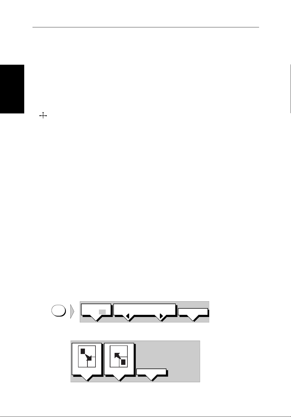
2-16 hsb
2.4 Radar Display Control Functions
Thissectiondescribeshowtousetherada rcontrols to:
Radar Disp lay Control
Functions
Using the Zoom Function
• Usethezoomfunctiontoenlargeaselectedarea.
• Offsetthecenterof the radar display.
• Momentarilyhidetheship’s heading marker(SHM).
2
PLUS Series Color LCD Display
ZMB
Ifyouwishtoseeasectionoftheradarpicture in more detail, you can use the
Zoomfunctiontomagnifytheselected area to twice its size.Therearetwo
zoomoptions:
• ZoomInto- The enlargedarea isdisplayedina quarter-screenZoom Win-
dowinthelowerrightcornerofthescreen.A box in the original radar pictureindicatestheenlarged area; you can move this using the contextsensitivecursor, thereby changing the image in the Zoom Window.
Note: If the areayouwish toenlargeisin thequarterof thescreenthatwill be
coveredbytheZoomWindow,youshouldoffsetthe center (see the next section)tomovetheareatoanotherpartofthescreenbefore selecting Zoom
mode.
• ZoomFrom- The enlargedarea isdisplayedin the mainwindow, withthe
originalradarpicturein a quarter-screenwindowinthelowerrightcorner
ofthescreen.A boxintheoriginalradarpictureindicatestheenlargedarea;
youcanmove thisusingthecontext-sensitivecursor, therebychangingthe
zoomedimage.
Note: Youcannotuse ZoomandWindows atthesametime:ifyouturnone on,
theotheris turned offautomatically,and restoredwhenthelatter isturnedoff
again.
➤ Toenlargeanarea:
1. PresstheDISPLAY key. The soft keys are updated.
DISPLAY
WINDOWS
OFF ON
SELECT
WINDOWS
2. PresstheZOOM softkey to display the following soft keys
x4
x2
ZOOM OFFINTO WIN FROM WIN
ZOOM...
D4208-2
D4188-2
Page 51

Chapter 2: Getting Started & Adjusting the Display 2-17
3. Presstherequiredzoomoptionsoftkey, INTO WIN orFROM WIN.
Thesoftkeysarecleared,andthecursorhas control of the zoom box that
indicatestheareatobeenlarged. This is indicated by the lettersZMB in
inversevideo,andthefour-headedcursorsymbol.Thezoomboxdefaults
toitslast-usedpositionsincepower-on.
4. Use the trackpadtomovethezoomboxtotherequiredarea,then press
ENTER. The selectedareaisshowninenlargedformat,eitherinthequar-
ter-screenZoom window(INTO WIN)orinthemainwindow(FROM WIN).
PressDISPLAY then ENTER t oexit the Zoom mode.
Alternatively, you can press and holdDISPLAY for2seconds.
➤ Youcanusethecontextsensitivecursor to select and move the enlargedarea
ZMB
inviewinthewindow(thelabelZMB is displayed). See Moving and deleting
itemswiththecontext-sensi tivecursoronpage 1-17
Offsetting the Center
RINGS
3nm
BRG
RNG
CURSOR
033° R
1.78nm
1/2
126°T
Figure 2-8: Radar Display Zoom Window
Offsetting the Center
Theradarpictureisnormallyshownwithyourvesselat the center of the
display. However,youcanmovethecenter,sothatyourvesselisof fsetbyup
to66%oftheradius,anywhereonthescreen.
RM RV3
AUTO
H-UP
RADAR ZOOM ( x2 )
T
ZMB
IR
Zoom Box, indicating the
enlarged area. You can move this
using the context-sensitive cursor,
to change the image in the Zoom
Window
Zoom Box cursor text
Zoom Window, providing a
times 2 enlargement of the area
shown in the Zoom Box
D3972-2
Note:Youcannotoffsetthecenterwhen the radar display is settothelongest
rangescale.
Page 52
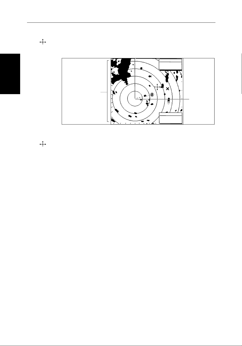
2-18 hsb
2
PLUS Series Color LCD Display
➤ Youusethecontextsensitiv ecursor to select and move the centeroftheradar
CTR
Hiding the Ship’s
Heading Marker
(SHM)
picture(thelabelCTR is displayed). See Moving and deletingitemswiththe
context-sensitivecursor on page 1-17
DEPTH
14.4m
Bearing scale markers
adjusted to point
towards the offset
centre position
203°
01h:30m
WPT
T 1.20nm
Offset centre
D3973-1
Figure 2-9: Radar Display with an Offset Center
➤ Toreturnthe center of the radar picturetothecenterofthescreen,select the
CTR
centerpoint(CTR ) thenpresstheCLEAR key.Thecenteris always reset to the
centerofthedisplaywhenyouturnontheRadardisplay.
Note:Whenthecenterisoffset,additi onalrange rings are displayedtothe
edgeofthe radarpicture,atthestandardringintervalfor thecurrentrange. If
youhaveselectedthelongestrangescale, you cannot offset thecenter.
Hiding the Ship’s Heading Marker (SHM)
Theradarpictureincludestheship’s headingmarker, whichisa linefromyour
vessel’s position to the edge of the pictureatthevessel’s current heading. In
thestandardHeadUpmode,theheadingmarkeris always a vertical line.
Ifyouwishtocheckforsmalltargetsthat may be hidden under the heading
marker,you can hide it momentarily using the context-sensitivecursor.
➤ Tohidetheheadin gmarker:
1. Positionthecursorovertheheadingmarker, so that the text SHM isdis-
played.
2. PressandholdCLEAR.Theheadingmarker is hiddenuntilyoureleasethe
CLEAR key.
Page 53

Chapter 2: Getting Started & Adjusting the Display 2-19
2.5 Chart Display Control Functions
Moving Around the Chart
You will normally operatethechartplotterwiththechartshowingyour
vessel’s current location. The defaultorientationisNorth-U p,and the vessel
movesacrossthe screen.Youwillneedto move thechartif your vesselmoves
outoftheareacurrentlydisplayed,or if you wish to examine or place
waypointsinanotherarea.Alternatively, you can home thecursorontothe
vesselusingFIND SHIP.
Therearefourwaysinwhichyoucanmovethechart:
• Usethetrackpadtomove the cursor totheedgeofthechart.The chart will
panacross.Thismethodisusefulif the area you wishtoseeisonlyjustoff
the screen.
• Usethecontext-sensitivecursor to change the chart center.
• Automaticallyre-centerthe vessel using the FIND SHIP soft key.
• Changethechartscaletozoom outandin toanewareacenteredonthecur-
sorposition.Thismethodisusefu lif the area you wish to see is a long dis-
tance away .
Functions
Chart Display Control
Changing the Chart Center
You can move the area of the chartdisplayedonthescreenusingthecontextsensitivecursor. This allows you to centeryourvesselinthemiddleofthe
screen,ortomovethechartsothatyour vesselisdisplayedof f-center
anywhereonthescreen.
➤ Tocenter the chart:
1. Usethetrackpadtomovethecursor tothevessel’sposition.Thecursortext
POS
POS
POS isdisplayed.
2. PressCLEAR. The chart is moved so thatyourvessel’spositionisinthe
centerofthescreen.
➤ Youusethecontextsensitivecursor to select and move your vessel’sposition
off-center(thelabelPOS isdisplayed).See Movinganddeletingitems withthe
context-sensitivecursor on page 1-17.
Page 54

Chart
2-20 hsb
Moving Around the
D4278-1
Figure 2-10: Changing the Chart Center
Using FIND SHIP
2
PLUS Series Color LCD Display
FIND SHIP isusedinchartmodetore-drawthechartwiththe vesselatthecenter
andthecursorhomedontothevessel.
GOTO SCREENROUTE FIND SHIP
D4160-1
WhenyoupressFIND SHIP thefollowingoccur:
• Thechartisre-drawnwiththevessel’s positioninthecenter.
• Thecursorishomedontothevesselposit ionandmoveswithit.
• Whenthevesselmovesneartheedgeofthechartwindow, the chart is
redrawntoplacethevesselandcursorat the center again.
• Thestatusbarindicatesvesselposition, speed and course over ground.
➤ Toreleasethecursorfromhomedmodepress the trackpadtomovethecursor
awayfromthevessel’s current position. The statusbarshowsthecursor
position,rangeandbearing.
Synchronize the Radar and Chart
Ifyouhaveacombinedradar/chartplotterdisplay, with chart and radar
windowsonandyouhaveselectedRadar/ChartSynch in Chart Set Up
(Section 7.7, ChartSetUpParameters), FIND SHIP can beusedtosynchr onize
theradarandchartimages.WhenyoupressFIND SHIP thefollowingoccur:
• Thechartis redrawnsothat itscenterposition matchesthatof theradardis-
play.
Page 55

Chapter 2: Getting Started & Adjusting the Display 2-21
• Theradarisredrawntothescaleandheadingmode of the chart.
• TheradarissettoTruemotionsothattheradarandchartimagesremain
synchronisedasthevesselmoves.
Note:Dependingonthetopologyofthecoastline ,the radar returns may not
relatetothechartedshoreline, theradarimagewillthereforebe differentto
thechartdisplay.Forexample,a gentlyslopingbeach withacliffseveralhundredmetresbeyondthechartedcoastli ne,the cliff is not shown on the chart
butwillbedisplayedontheradarimage.
Changing the Chart Scale
TheRANGE keyallowsyoutochangethechartscalesothatyou can see a
smallerorlargerarea on the screen.
Plottermodeisavailabletoall owyou to zoom into a smaller area, even when
nochartdata isavailableforthatscale.Section 7.7describeshow tosetplott er
modeon/off.
You can change the chart scalefortwopurposes:
• Toseeeithermoredetail(of a smaller area) or a largerarea(inlessdetail )
onthescreen.
Chart
Moving Around the
• Tomovethedisplay to anotherareaofthechart, by zoomingouttoasmall
scalechart,thenzoominginonanothe rposition centered on the cursor.
Thecartographicdetailavailable on charts varies accordingtothechartscale
andsomeareasincludedetailat smallerscalesthanothers.This can cause
blankareasonthedisplaywhenadjacentareas with differentlevelsofdetail
aredisplayed.To reduce this affectyoucanusetheChartSetUpoptions(see
Section 7.7) tosetchart displaydetailtosimple.Then,asyouzoomin,charted
areasaredisplayedbutwithlessdetail shown.
EachtimeyoupresstheRANGE key, the chart scale changes to the next
availablesetting.Thestatus bar indicates the distancefromtoptobottomof
thescreen,innauticalmiles.
Vertical distance
displayed on chart
6nm
Status Bar
CSR 50 45'980N
POS 001 01'490W
D4175_1
RANGE
Increases the
chart distance
Decreases the
chart distance
Figure 2-11: Changing the Chart Scale
Page 56

2-22 hsb
➤ Tochange the scale quickly,pressandholdtherequired arrow ontheRANGE
key.
RANGE
Moving Around the
Thedistanceindicatorattheleft-hand end of the status bar is updated
wheneveryouchangethechartscale.
2
PLUS Series Color LCD Display
Chart
RANGE
➤ Tozoomintoalarger-scale (more detailed)chart:
1. Use the trackpadtopositionthecursorinthe area you wish to see in more
detail.
2. PressthelowerpartoftheRANGE key to zoom into the area.
Thesectionofthe chart aroundthecursoris enlargedtofil lthe screenwith
alarger-scale chart showing more detail. The cursor isnow positionedin
the centerof the screen.
Thedistanceindicatedatthetop left of the screen is updated.
3. If furtherchartenlar gementis available using the currentchartcardyou
canpressthebottomoftheRANGE key to zoom in again, re-positioning
the cursor first if required.
Anareaoffurtherchartdetailis indicated by a box around the area as
showninFigure 2-12.
Chart Boundary indicates further
detail is available inside
Figure 2-12: Chart Boundaries
4. When no furtherchartdetailisavailable,as you press the bottom of the
RANGE key,theeffectdepends on whether Plotter Mode is on or off as
follows:
D4279-1
Page 57

Chapter 2: Getting Started & Adjusting the Display 2-23
• IfPlotterModeisOff,the chart scale remains unchanged,indicating
thesmallestchartscaleis displayed.
Note:IfPlotterModeisOffandthecursorishomedto the vessel (see
Using FIND SHIP on page 2-20),ifthevesselmovesoutsidean areaof
availablecartography,thechartwillautomaticallyre-scaleto the next
rangewithcartography.
• IfPlotterModeisOn,the scaleisdecreased andthemessageNO CHART
DATA isdisplayed.The vessel, waypoints,routesandtracklinesaredis-
playedwithoutcartography.
Thechartinformationisrestoredwhenyoureturntoachartscaleforwhichthe
information is available.
Radar/Chart Overlay
RANGE
➤ Tozoomouttoasmaller-scale(lessdetailed)char t,simplypresstheupperpart
oftheRANGE keyasmanytimesasrequired.
Radar/Chart Overlay
Ifradardataisavailable,as a function of the combined radar/chartdisplayor
fromanotherdisplayconnectedon
thefull-screenchartplotterdisplay. The radar/chart overlayoptionhelpsyou
todistinguishbetweenfixed,charted objects and otherobjectsthatcouldbe
movingvessels.Someradarcontrolsare available in overlay mode.
Thefollowingcriteriamustbetruefor radar/chart overlay to function
correctly:
• Positionandheadingdataare provided so that vessel positionandorientationcanbedetermined.SeeHeadingandPositionData on page 1-9 for
furtherdetails.
• Thevesselmustbedisplayedonscreen.
• Thechartplottermustbe inNorthUporCourse Upmode(seeSection 7.7).
• Thechartplotterrangemustbebetween1/4nmand 48nm (equivalent to a
radarrangeof1/8nmto24nm).
2
hsb
,theradar targetscanbe overlaidonto
• Customrangescalesaredisabledon the radar.
• Theradarmustbetransmitting.
To ensurethevesselremainsonthescreen,youcoulduseFind Ship(seeUsing
FINDSHIPonpage 2-20) to home the cursor onto the vessel.
WhenRadar/Chartoverlayisswitchedon, the status bar indicates OVL.Ifthe
optionisswitchedonbuttheoverlayis not visible (because one of the above
criteriahasfailed),the status bar indicationchangesto(OVL).
Page 58

2-24 hsb
WhenRadar/Chartoverlayisswitchedon the soft key MORE... provides
accesstotheSCREEN soft key and to the radar controls TARGETS and MARPA.
TheradarGAIN controlisalsoactivein overlay mode.
Radar/Chart Overlay
Note:Radar/Chartoverlayisdisplayedat the current chart range. You
shouldbeawarethatifradarisshownonanyotherdispla y,its range will
matchthatdisplayedonRadar/Chartoverlay.Conversely, if you change the
radarrangeon anydisplay,the Radar/Chartoverlayimagewillchangeto the
newradarrange.
➤ Toselectradar/chart overlay:
1. PresstheDISPLAY keytoshowtheDISPLAY pop-up,thenifnecessarypress
DISPLAY
againtoselectChartmode.
2. PresstheOVERLAY OFF ON soft key to toggletheoptionon.
Thetwohighestintensityradarreturns are displayed in purple, overthechart
image.Theradar image istranslucent,so thatcharttext,contours andoutlines
arevisiblebeneaththeradartargets.
2
PLUS Series Color LCD Display
Page 59

Chapter 2: Getting Started & Adjusting the Display 2-25
2.6 Typical Chart Scenarios
Thefollowingillustrationsprovideoperatingguidelinesfortypicalnavigation
scenarios.These scenarioscanbe usedasa trainingguide;theyshowyouhow
toperformaparticularoperat ionand they introduce many of the chartplotter
functions.
Eachscenarioindicatesthekeypressesrequiredtoperformparticulartasks.A
typicalchartplotterscreen image is shown for each task.
Thescenariosassumeyouhavereadtheprevioussections of this chapter and
thatyouarefamiliarwiththeOperatingControls. Full operatingdetailsfor
eachfunctionareprovidedin Chapter 5 and Chapter 6.
Operatingguidelinesareprovided for the following scenarios:
• WorkingwithWaypoints
PlaceaWaypoint
GotoaWaypoint
• MakeandFollowaRoute
CreateaRoute
FollowaRoute
Typical Chart
Scenarios
• ReviewthePassagePlan
Vi ewRoute Information
ChangetheSOG, Hours and ETA.
• DisplayingtheRadarImageandSynchronizingRadar & Chart
ChangingtheFull-ScreenMode&SelectingHalf-Screen Windows
RadarandChartSynchronization(Find Ship)
CursorEcho
Page 60

2-26 hsb
2
PLUS Series Color LCD Display
Place and Goto a Waypoint
1
Place and Goto a
Waypoint
1. Press MARKS
2. Position Cursor as required
2
Press the soft key
Press the soft key to go to the
waypoint selected by the cursor.
3
D4267-1
Page 61

Chapter 2: Getting Started & Adjusting the Display 2-27
4
The vessel navigates towards the target
waypoint
See:
5.3 Working wth Waypoints
Go to an individual Target Point,
page 5-26.
D4267-2a
Waypoint
Place and Goto a
Page 62

2-28 hsb
2
PLUS Series Color LCD Display
Make and Follow a Route
#
1
Make and Follow a
Route
GOTO SCREENROUTE FIND SHIP
MAKE
EDIT
ROUTE
ROUTE
CLEAR
ROUTE
MORE¬
Press the soft key
2
Press the soft key
3
1. Position Cursor - in this example
over an existing waypoint
2. Press the soft key
Position Cursor for next waypoint,
then press soft key.
Repeat to plot all waypoints in
sequence.
4
D4268-1
Page 63

Chapter 2: Getting Started & Adjusting the Display 2-29
5
5
Press the soft key. The route becomes
Press the soft key. The route becomes
the current route.
the current route.
6
6
GOTO SCREENROUTE FIND SHIP
GOTO SCREENROUTE FIND SHIP
Plan
Review Your Passage
GOTO
GOTO
CURSOR
CURSOR
STOP
STOP
FOLLOW
FOLLOW
GOTO
GOTO
WAYPOINT
WAYPOINT
GOTO
GOTO
CURSOR
CURSOR
FOLLOW
FOLLOW
ROUTE
ROUTE
RESTART
RESTART
XTE
XTE
WAYPOINT
WAYPOINT
ADVANCE
ADVANCE
Press the soft key
Press the soft key
7
7
Press the soft key
Press the soft key
8
8
The vessel starts to navigate to the
The vessel starts to navigate to the
first (target) waypoint in the route.
first (target) waypoint in the route.
See:
See:
5.4 Working wth routes,
5.4 Working wth routes,
Follow a route, page 5-24.
Follow a route, page 5-24.
Other Follow Options, page 5-25.
Other Follow Options, page 5-25.
D4268-2a
D4268-2a
Page 64

2-30 hsb
Review Your Passage Plan
2
PLUS Series Color LCD Display
ROUTE
GOTO SCREEN
FIND SHIP
Review Your Passage
1
Press the soft key
Plan
MAKE
ROUTE
REVERSE
ROUTE
EDIT
ROUTE
SAVE
ROUTE
CLEAR
ROUTE
ROUTE
LIST
MORE¬
MORE¬
Press the soft key
Press the soft key
2
3
4
1. Use the trackpad to move
selection bar over required route.
2. Press the soft key
Time defaults to ETA - and assumes
the current time is the start time.
5
D4269-1
Page 65

Chapter 2: Getting Started & Adjusting the Display 2-31
6
See:
Displaying Route Information
page 5-18.
Change the TIME to HOURS - the display
indicates it will take 32 minutes to reach
the destination. You can change the
PLANNED SOG; the display updates to
indicate TIME required at the planned
speed.
Plan
Review Your Passage
D4269-2a
Page 66

2-32 hsb
2
PLUS Series Color LCD Display
Displaying the Radar and Synchronizing Radar & Chart
1
Displaying the Radar
and Synchronizing
Radar & Chart
1. Press DISPLAY -- then press
twice more to select RADAR.
2. Press the soft keys to set windows
ON. The Chart window is the default
selection.
3. Press ENTER.
2
ROUTE
SYSTEM
SET UP¬
GOTO MORE¬
CHART
SET UP¬
SET UP¬
TRACK
RDR CHRT
GPS
SETUP¬
Press the soft key. You can control
the chart cursor.
1. Press MENU.
2. Press the soft key
3
D4293-1
Page 67

Chapter 2: Getting Started & Adjusting the Display 2-33
SCREEN
f
GOTO MORE¬ROUTE RDR CHRT
FIND SHIP MORE¬
RDR CHRT
1. Move selection bar over
Radar/Chart Synch.
2. Press the soft key.
3. Press ENTER twice.
Press the soft key.
Press the soft key to synchronise the
chart & radar images.
4
Radar & Chart
and Synchronizing
Displaying the Radar
5
6
The radar and chart windows are
synchronised and the cursor is
'homed' on the vessel
Move the chart cursor -- you can see
chart cursor move on the radar
screen.
You can move the cursor over
a radar target to determine its
identity on the chart
See:
2.3 Controlling the Display
6.5 Cursor Echo
7.3 System Parameters
7.6 Chart Set Up
7
D4293-1a
Page 68

2-34 hsb
Displaying the Radar
and Synchronizing
Radar & Chart
2
PLUS Series Color LCD Display
Page 69

Chapter 3: Standard Radar Operations 3-1
Chapter 3: Standard Radar Operations
3.1 Introduction
Thischapterprovides detailedinstructionsforthestandardoperationsofyour
Pathfinderradar. Additional functions,thatareavailableonintegrated
systemswith appropriatedatasources,aredescribedinChapter 4. Ifyouhave
acombinedradar/chartdispla yrefer to Chapter 5 and Chapter 6 for
informationonchartingoperations.
You canusethis chapterwiththe radardisplayset tosimulatormode,oronthe
waterafteryouhaveinstalledandsetup yourPathfindersystem.
Thischaptercoversthefollowingtopic s:
• Rangecontrol.
• Interpretingandadjustingtheradarpicture,including adjusting the gain,
seaclutterandrainclutter, changing the targetsdisplay, and tuning the
radar.
• Measuringrange(dist ances)andbearingsusingVariable Range Markers
(VRMs)andElectronicBearingLines(EBLs).
• Settingupguardzonesandhandlingalarms.
• UsingMARPA for target trackingandriskanalysis.
Note:Untilyouarefamiliarwithinterpretingtheradardisplay,youshould
takeeveryopportunitytocomparethe radar’s display patternswithvisual
targets,suchasothervessels,buoys and coastal structures.Youshouldpracticeharbourandcoastalnavigat ionduringdaylightand inclearweather conditions.
Ifyouhavea combinedradar/chartplotteror have an
aspartofanintegratedsystem,youcan identify objects usingeithertheradar/
chartoverlay(seeRadar/Ch artOverlay on page 2-23) or the cursor echo
feature:Withcursorecho on(seeSection 4.5 andChapter 7) youcanselectan
objectontheradardisplay, the cursorisrepeatedonthechartdisplaysoyou
canchecktheobject’s identity.
2
hsb
seriesChartplotter
Introduction
Page 70

3-2 hsb
3.2 Range Control
Theradarpicturecanbeviewedatvariousscales.Theshortestrangescale
givesamaximumrangeof
tothetopof theradarpicture.The longestrangescalegivesamaximumrange
of between24and72nauticalmilesdependingonyourscanner.
1
/8nauticalmiles,measuredfromthe default centre
2
PLUS Series Color LCD Display
Range Control
shiptolandmasses,weatherfrontsand large ship targetsinorbeyond
view.
•Theshort range scalesprovidegreaterdetailofthe radar echoes close to
yourvessel,andshouldbeusedasyouapproachthe coastline, harbour or
othervesselsinthearea.
ThePathfinderPlusRadardisplayincludesconcentricrange rings,whichyou
canusetohelpyoutojudgedistancesontheradarpicture. Their number and
spacingareadjustedautomaticallyifyouchangetherangescale. They can be
turnedoff(seeSwitchingRadar Range Rings or Chart Grid On and Off on
page2-13).
The Standard Range Scale
Detailsofthestandardrangesthat can be selected are shown in the table
below. If youwish,you can customizetherange scalesbyspecif yingdifferent
ranges,asdescribedinSection 7.4,RadarSetUp Parameters.
Table 3-1: Radar Range Scales
•Thelong range scales providethebestoverviewofyourvessel’s relation-
Maximum Range
(nm)
Number of Range
Rings
Range Ring Interval
(nm)
0.125
0.25
0.5
0.75
1.5
3
6
12
24*
48*
72*
*Themaximum rangedepends onyourscanner type,as detailedinthe PathfinderPlus Radar
ScannerOwner’sHandbook.
2
2
4
3
6
6
6
6
6
6
6
0.0625
0.125
0.125
0.25
0.25
0.5
1
2
4
8
12
Thenumberofrangeringsshowninthetableisthenumbertotheselected
range.Additionalrangeringsare displayed to the edge of the radar picture,at
thestandard ring interval for the currentrange, and are visiblewhenthecentre
is offset.
Page 71

Chapter 3: Standard Radar Operations 3-3
Changing the Range
Increases
RANGE
the range scale
Decreases
the range scale
Figure 3-1: Changing the Radar Range
RANGE
AUTO MAN
➤ Each time you press the RANGE key, the range changestothenextavailable
setting.Thesystemwillbeepthree times if no further range scaleisavailable.
➤ Tochange therangequickly,pressandhold therequiredarrowon theRANGE
key.
Therangescaleandrangeringinterva lindicators, at the left-handendofthe
statusbar,are updated whenever you change the range.
Determining Actual Radar Range
Theactualmaximumradar range isessentiallyline-of-s ight,andislimitedby
theheightofthescannerandtheheightofthetarget as shown in Figure 3-1.
Table 3-2 lists some range examples:
a
1
h
Radar
R
max
h
H
R
= radar horizon of antenna (
max
Figure 3-2: Determining Radar Range
R
max
maximum radar range
radar antenna height
target height
Selected
range scale
6nm
R
max
Earth
= 2.23 ( h + H )
a
) + radar horizon of target (a2)
1
Range ring
spacing
RR
1nm
Status Bar
a
2
in nautical miles
in metres
in metres
343°T
D3939_1
Changing the Range
H
Cliff
D1643-2
Table 3-2: Radar Range
Antenna Height (m) Target Height (m) Maximum Range (nm)
3 3 7.8
3 10 10.9
5 3 8.9
5 10 12.0
Note:Therangesshown in thetableare theoreticalmaximumranges.The radarhorizonisgreaterthantheoptica lhorizon, but the radar can only detect
targetsifalargeenoughtargetisabovetheradar horizon.
Page 72

Picture
3-4 hsb
2
PLUS Series Color LCD Display
3.3 Interpreting and Adjusting the Radar Picture
Navigationalechoesmaybelarge,small, bright or faint, dependingnotonly
onthesizeoftheobjectbutalsoonitsorientationandsurface.Dif ferent
objectsreflecttheradarsignals in differentways.Forexample,vertical
objectssuchascliffsreflect signals betterthanslopingonessuchas
Adjusting the Radar
Interpreting and
sandbanks.
Highcoastlinesandmountainouscoast alregions can be observed at the
longestradarrange.However, thefirstsightofland maybea mountainseveral
milesinlandfromthecoastline.The actual coastline may not appear on the
radaruntilthevesselisclos etotheline of sight distance.
Theradarindicationmaynotbesimilartoyourvisualobservation;a nearby
smallobjectmayappeartobethesamesizeas a distant large objecton the
radar. However,withexperiencethe approximatesizeofdifferentobjectscan
bedeterminedbytherelativesize and brightness of the echoes.
Sometargets,suchas buoys and small boats, can be difficulttodifferentiate,
sincetheybobandtossaboutinthewavesanddonotpresenta consistent
reflectingsurface.Consequently,theseechoes have a tendency to fade and
brightenand,at times,todisappearmomentarily.Buoys andsmallboatsoften
resembleeachother, but boats can usually be distinguished by theirmotion.
Notallradarechoesareproducedbyhardnavigational items. Some echoes
maybereceivedfromirregularitiesonthesurfaceofthewater,particularlyat
closerange(sea clutter),orfrom rainorsnoweitheraroundthevessel orinthe
distance.Inaddition,someechoesmaybeindirectreturnstotheradarscanner,
providingfalseechoesormultipl eechoes.
Theef fectsof manyfalseechoescanbeminimized,andthetargetpresentation
clarifiedusingthecontrolssummarizedbelow. This section explainshowto
interprettheradarpictureand how the controls affectthedisplay. It provides
instructionsforadjustingthe settings, describesthecircumstancesinwhich
theyshouldbeadjusted,andhowthey interact with each other.
Table 3-3: Controls to Adjust the Radar Picture
Control Option Function Default Setting
GAIN GAIN
SEA
RAIN
FTC
MULTI TUNE Fine tunes the receive AUTO
TARGETS
Soft Key
INT REJ
EXPANSION
WAKES
Controls the strength of the target returns
Reduces sea returns
Reduces close rain or snow returns
Reduces distant rain or snow returns
Turns interference rejection on/off
Turns target expansion on/off
Turns wakes on/off and selects wakes length
AUTO
AUTO-HARBOUR
OFF
OFF
ON
OFF
OFF
Page 73

Chapter 3: Standard Radar Operations 3-5
Identifying False Echo Returns
Notallechoesaredirectreturn sto the radar antenna. Occasionallysignals
appearatpositionswherethereisnoactualtarget.Thesearecalledfalse
echoes,andmaybecausedbysidelobes,ghostimages,indirectechoes or
multipleechoes.
Thissectionbrieflydescri besthe echo patterns that can be producedbyfalse
echoesandthelikely cause.Itshouldbe noted thattheradaroperator, through
observation,practice,and experience, can generallydetecttheseconditions
veryquickly. These effectscanusuallybe minimizedusingtheradar controls.
Returns
Side Lobes
AsmallpartoftheRFenergyfromeach transmitted pulse is radiatedoutside
thesinglenarrowbeam.Thisproducesside lobe patterns, shownin
Figure 3-3.
Sidelobeshavenoeffecton distant or small surface objects.However,the
echofromalar geobject at shortrangemayproducean arc on theradarscreen
similartoarangeringoraseriesof echoes forming a broken arc. Side-lobe
echoesnormallyoccuratrangesbelow 3nm, and can be reduced by adjusting
the SEA control.
Main lobe
Side lobe Side lobe
Antenna
True echo Side echoes
Arc
Figure 3-3: Side Lobes
D1638-2
Identifying False Echo
Page 74

3-6 hsb
Indirect Echoes
Thereare severaltypesofindirectechoesorghostimages-someexamplesare
showninFigure 3-4. These sometimeshavetheappearanceoftrueechoes,
butingeneraltheyareintermitt entand poorly defined.
2
PLUS Series Color LCD Display
Identifying False Echo
Returns
Indirect (false) echoes
False echo
Passing
ship
True echo
Mast
or funnel
True echo
False echo
D1641-2
Figure 3-4: Indirect Echoes
Multiple Echoes
Multipleechoesappearif there is a large targetwithawideverticalsurface at
acomparativelyshort range.Thetransmittedsignalwill be reflectedbackand
forthbetweenthetargetand your own ship. Multiple echoes thereforeappear
beyondthetruetarget’s echo on the same bearing,asshowninFigure 3-5.
Thisisnotverycommon.
MULTIPLE ECHOES
Multiple echoes
True echo
D1642-1
Figure 3-5: Multiple Echoes
Blind Sectors or Shadow Effect
Funnelsandmastslocatedneartheanten na,may cause shadows. In shadow
areasbeyondtheobstructionthere will be a reduction of the beam intensity,
althoughnotnecessarilya completecut-off.However, there will be a blind
sectorifthesubtendedangleis more than a few degrees. There may also be
multipleechoeswhichextend behind the obstruction.Thisshouldbe avoided
bycarefulselectionofthescanner site prior to installation(Chapter 8).
Page 75

Chapter 3: Standard Radar Operations 3-7
Adjusting Gain, Sea Clutter, Rain Clutter and Tune
AutomaticadjustmentofGain,Sea and Tune is available,alternativelyyou
cansetanyoftheseparameterstomanualandusethetrackpadto adjust its
GAIN
MULTI
value.Rainclutterisadjuste dmanually using the RAIN orFTC control.GAIN,
SEA, RAIN andFTC are accessedfromtheGAIN key;TUNE is accessedfromthe
MULTI key.We recommend that you leave the TUNE controlin Auto mode.
Note:Gain,SeaandTunecanonlybeadjustedifthecontrolisset toManual
adjustment.
MANUAL MANUAL
O
F
F
FTC GAIN
O
F
F
RAIN SEA
75%
50%
D3936-3
WhenyouselectmanualGAIN,SEA or TUNE adjustmentthe soft key icon
showsaverticalsliderbar.Asyoupressthetra ckpad, the value is indicatedin
the slider.
WhenyouswitchFTC orRAIN On,thesoftkey icon showsaverticalslider bar.
Asyoupressthetrackpad,thevalueisindicatedintheslider.
Ifyouchangethesettings,thenewGAIN,SEA andTUNE modes(autoor
manual)andvaluesremainseteven when you turn the radar offandonagain;
RainandFTCareresettoOffat power-on.Thestatusbarindi cateswhich
controlsareswitchedtoAutoorOn,as shown in Figure 3-6.
Status Bar
3nm
RINGS
1/2
126°T
Gain, Sea and/or Tune set to Auto
WKS
TM TV3
H-UP
FTC on
AUTO
GST
FTCEXRCGZIR
Rain on
D3987-2
Figure 3-6: Radar Status Bar
and Tune
Clutter, Rain Clutter
Adjusting Gain, Sea
GAIN
MULTI
➤ Toadjust a parameter:
1. Selectarangeappropriatetotheadjustmentyou wish to make. The optimum Tunesettingvaries slightly for differentranges,dependingon the
pulsewidthused.
2. PressGAIN orMULTI.Theslider soft keys are displayed.Thelast-used
sliderishighlighted(displayed in inverse video) to show thatitisselected.
3. Presstherequiredsoftkeysothatthe slider box is highlighted.
TheTUNE and GAIN softkeystogglethe controlbetweenAuto and Manual
mode.TheSEA soft key toggles the control between Auto-Harbour,Auto-
OffshoreandManualmode.Ifyou selectManualmodethelastautosetting
isretained.You canonlymovethesliderifthecontrolis set to Manual.
Page 76

Clutter, Rain Clutter
3-8 hsb
4. Usethetrackpa dtomovetheslider upordown.Youcan pressandhold the
controltomovethesliderquicklyrather than in single steps.
Theimageonthescreenchangesas youmovetheslider ,sothatyoucansee
theeffectofyouradjustment.
Ifyou selectMANUAL TUNE adjustment,an8-stepsignal -strengthindicator
barisdisplayedabovetheslider. Adjust the slidertoobtainthemaximum
Adjusting Gain, Sea
readingontheindicator.
2
PLUS Series Color LCD Display
and Tune
Note:Becausethechangestothesettingsare made immediately, you cannot
reverttotheprevioussettingby pressing CLEAR.
5. When you have set allthecontrolstothelevelsyourequire,press ENTER,
orCLEAR toclear the slider display. Thestatusbarisupdatedtoindicate
whichcontrolsareswitchedtoAutoorOn.
Gain Control and Sea Control
TheGAIN controlcanbesettoeitherAutoorManual.In Automode,the
PathfinderPlus radaroptimizesthesetting.TheSEA control canbesettoAuto-
Harbour(default),Auto-Offshore or Manual mode. In Auto-Offshoremode,
thePathf inderPlusRadaroptimizesitssettingstoaccountfortheeffectsof sea
clutter. In harbours or closeproximitytolanddifferent auto settingsmay
benecessarytocaterfortheeffectsof land clutter .Toavoidlosing small
targetsitistherefore advisable to set the Sea controltoAuto-Harbour
mode.Alternatively, set both Sea and Gain to Manual mode then adjust
the settings to ensurethat all close smalltargets arevisible.
TheGAIN controladjuststhelevelofthedisplayof signals received from the
scanner;itisequivalenttoavolumecontrol on a radio.
BecausetheSEA controlaf fectsthegain,you mayneedtomanually readjustit
ifyoumanuallychangetheGainsetting.
MANUAL
50%
GAIN
Gain Control
Whenthe GAIN controlis set to Manual, you should check it every timeyou
changetherangescale.
Onlongrangesettings,thegainshouldbe set to give a slight speckle in the
backgroundoftheradarpicture.Do notsetthegaintoolow, or you may miss
smallorweaktarget s.
Onshorterranges,youmaywishtoreducethegainslightl yto reduce the
speckleandthereforeimprovetarget definition.
Page 77

Chapter 3: Standard Radar Operations 3-9
Sea Clutter Control
MANUAL
Radarret urnsfromwavesaroundyourvesselcanclutterthecentreofthe radar
picture(seeFigure 3-7,makingitdifficulttodetectrealtargets.Suchsea
75%
SEA
clutterusuallyappears as multipleechoesonthedisplay at shortrangescales,
andtheechoesarenotrepetitiveor consistentin position.With highwindsand
extremeconditions,echoesfrom sea clutter may cause dense background
clutterintheshapeofanalmostsoliddisc.
D3968-1
Figure 3-7: Sea Clutter
and Tune
Clutter, Rain Clutter
Adjusting Gain, Sea
A
U
T
O
TUNE
TheSEA control reducesthegainlevel in theareasnear your vessel,extending
upto3to5nm dependingonthewaveand seaconditions.Thishastheeffectof
reducing the sea returns to intermittent small dots, while small targets are still
visible.Gainlevelsfurtherfromyour vessel remain unchanged.
YoucanusetheGainandSea controltohelpminimizetheeffectsofsidelobes
(seeIdentifyingFalseEcho Returns on page 3-5).
Note:Onshortrangescales,donotsettheSeacontrol so high that all clutter
isremoved,sincethiscouldstop you seeing echoes from close targets.
Tuning the Receiver
TheTUNE control is usedtofinetunethe receiver inthescannerformaximum
targetreturnsonthe display. InAutomode,the radartunesitselfautomatically
onallrange scales.WerecommendthatyouleavetheTUNE cont rol inAuto
mode.
IfyoudosettheTUNE controltoManual,you will need to adjust it about 10
minutesafteryouhaveturnedontheradar, since the requiredsettingchanges
oncethemagnetronhaswarmedup.
You should adjust the controltoobtainthemaximumsignalstrength,as
indicatedinthe8-stepbarabovethe slider.Ifyoucannottunetheradar
successfully, referto Section 7.6 for information on the TunePresetfunction.
Page 78

and Tune
Clutter, Rain Clutter
3-10 hsb
Rain Clutter Control, using RAIN and FTC
Theradarcan seeechoesfrom rainorsnow.Returnsfromstormareasandrain
squallsconsistofcountlesssmallechoes that continuously changesize,
intensity, andposition.These returns,shownin Figure 3-8,sometimesappear
aslargehazyareas,dependingontheintensityoftherainfallor snow in the
Adjusting Gain, Sea
O
F
F
RAIN
stormcell.
TheRAIN andFTC controls are used to reducethisclutter, so that targets
maskedbythecluttercanbeseenontheradar picture.
•TheRAIN controlis used to reduce largecluttermassesaround your vessel
causedbyrainorsnow.
•TheFTC ( F astTime Constant)controlisusedtoreducerainclutter at a dis-
tancefromyourvessel,suchasthatshownbelow.
2
PLUS Series Color LCD Display
O
F
F
FTC
D3967-1
Figure 3-8: Rain Clutter
When the FTC co ntrolisturnedup,onlythe leadingedgeoflarge(rain clutter)
echoesisdisplayed,whilethe effect on smaller(ship)echoesisonlyslight.
Thismeansthatyoucanalsousethecontrolon shorter ranges to distinguish
betweentwoverycloseechoesonthesamebearing,which may otherwise
mergeandappearasoneecho.
Whenthe FTC contro lis turned up, the receiver is lesssensitive,andthereisa
reductionofbackgroundnoiseand fill-in returns from landandlargetargets.
You shouldthereforeturn the controldownwhenitsuse is not required.Since
stormcellsareusuallyvisibl efor long distances due to their extremealtitude,
youmaywishtoleavethemdisplayedsothatyoucan observe the location of
badweather.
If you turn the RAIN orFTC control Off(equivalenttosetti ngthe level to 0%),
theactualsettingisstored ,and restored when you turn the controlonagain.
Note:RAIN and FTC areresetto Off at power-on.
Page 79

Chapter 3: Standard Radar Operations 3-11
Changing the Targets Display
ThePathfinderPLUSRadarallowsyoutoimprovetar getvisibility by
changingthefollowing:
• Interferencereject ion
• Targetexpansion
• Targetwakes
Theseparametersareaccessedfrom the default soft key TARGETS.
Thissectionexplainshowtochangethese modes and describes the effectof
eachmode.Thecurrentsettingsare shown at the right-hand end of the status
barasshowninFigure 3-9.
Status Bar
3nm
RINGS
1/2
126°T
Figure 3-9: Status Bar
➤ Tochangethe settings of the targetmodes:
1. PresstheTARGETS default softkey.
Thetargetoptionsoftkeys are displayed, with the currentselectionshighlighted.
TARGETS
INT REJ
OFF ON
EXPANSION
OFF 1 2
2. Presstheappropriatesoftkeytotogglethe required setting betweenOFF
andON.
Wakes on Target Expansion on
TM TV3
H-UP
Interference Rejection on
WAKES
OFF S M L
AUTO
GST
CLEAR
WAKES
Display
Changing the Targets
WKS
FTCEXRCGZIR
D3986-2
D3642-3
WAKES
OFF S M L
Note:Ifanoptionisnotavailableforthecurrentsetting,itssoftkeylabelis
grey.Whenyoupressthekey,thesystembeeps and the setting remains OFF.
FortheWakes mode, press the WAKES sof tkey to step the highlighted
selectionthroughthewakeoptions .
You can use the soft keys to changethesettingsofanyorallthemodeson
thisdisplay.
3. When the requiredoptionsarehighlighted ,press ENTER.Thescreen
returnstothedefaultdisplaywiththenewmode(s) inoperation.The status
barisupdatedtoindicatewhichcontr olsare switched on.
Page 80

Changing the Targets
Display
3-12 hsb
Interference Rejection
Mutualradarinterferenceislike lywhen two or more radar-equippedvessels
INT REJ
OFF ON
areoperatingwithinrangeof each other.Thisusuallyappearsas a series of
smalldotsmovingtoandfromthedisplaycenter in a straight line or a long,
sweepingcurve.Thistypeofinterfer enceismostnoticeableatlongranges.
D1639-1
Figure 3-10: Interference Rejection
ThePathfinderPlusRadarincludesa mechanismthatautomaticallyreduces
suchinterference.Thismechani smis normally left switched on. However,if
youwishtodetectthepresenceof other radars inthevicinity, you can turn off
theinterferencerejection.
2
PLUS Series Color LCD Display
EXPANSION
OFF 1 2
WAKES
OFF S M L
CLEAR
WAKES
Target Expansion
You can make targetseasiertoseebyexpandingthem.Targetexpansionuses
acombinationofsignalprocessingtechniquesandpulselengthoverrideto
increasethe sizeoftar getsseenon thescreen.However,thismay compromise
rangeresolution.Two levels of targetexpansionareavailable,withlevel2
providinggreaterexpansio nthan level 1.
Target Wakes
You can see the directionandspeedwithwhichtarg etsare moving relative to
yourvesselbyselectingthetarget wakesdisplayoption.
Whenwakesareswitchedon,thetargetis displayed at the brightestleveland
thepreviouspositionsoftargets are retained at successivelyfainterlevelson
thescreen.Youcanselectlong,mediumorshortwakes,whichretain
informationfrompreviousscans at a reduced video level.
You can clear existingwakesfromthedisplayby pressingtheCLEAR WAKES
softkey. The soft key is only available when wakes areswitchedon;the
displaystartsshowingnew wakes as soon as the oldwakeshavebeencleared.
Whenwakesareswitchedoff,nonewwakesaredisplayedandexistingwakes
arecleared.
Page 81

Chapter 3: Standard Radar Operations 3-13
3.4 Measuring Range and Bearing Using VRM/EBLs
ThePathfinderPlusRadardisplayallows you to specify up to two Electronic
BearingLines(EBLs),eachwithanassociatedVariableRangeMarker
(VRM), using the VRM/EBL key.
AstandardVRMisdisplayedasacirclewithitscentre on your vessel’s
position,andit’s EBL is displayed as a line fromthe origintotheedgeofthe
radarpicturedisplay.However,each pair can be floated,sothattheorigi ncan
bemoved.
3nm
RR
OFF
126°T
VRM
H-UP
AUTO
IR
T
Floated VRM2
(long-dashed line)
Floated EBL2
(long-dashed line)
VRM1 (short-dashed line)
EBLs
Bearing Using VRM/
Measuring Range and
EBL1 (short-dashed line)
VRM/EBL 2
015°
TBRG
096
RNG nm
CURSOR CURSOR
146°
1.70
RNG nm
50°47^72N
TBRG
001°10^58N
VRM/EBL 1
BRG
243°
0.98
RNG nm
T
VRM/EBL data boxes
Two cursor readout boxes
D3974-1
Figure 3-11: EBL and VRM Displays
Note:WhenusingVRM/EBLs,youmaywishtoturnofftherangeringsto
make the VRMs clearer (see Section 2.4).
VRMs moveifyouchangetherangescale,sothattheactualrange you have
markedismaintained.VRM/EBLsalsomove if you offset the centre.
WhenaVRM/EBLpairisactive,itsbearingand range are displayed in its
associateddatabox,whichcan be moved,deletedorreinsta ted.
Thebearinginformationisdispl ayedas either the bearing relativetoyour
vessel’s heading or (if heading data is availablefromapositionfixeror
compass)theactualbearingin degrees magnetic or degrees true.Theseare
controlledbythesetupparameters (see Section 7.4).
TheVRM/EBL functionsallowyoutoperformthefollowingtasks:
Page 82

from Vessel
Bearing to Target
3-14 hsb
• Measuretherangeofatargetor point from your vessel’sposition,using a
VRM
• Measurethebearingofatarget orpointfromyourvessel’s position, using
anEBL
• Measuretherangeandbearing between any two pointsontheradar,using
Measuring Range and
the FLOAT function
Note:Analternativemethodofmeasuringrangeandbearing istouse thecursordatabox:Ifthecursorreadoutisset todisplayrangeandbearing(rather
thanLat/Long),youcandeterminetherangeand bearing by moving the cursoroverthetargetandcheckingthecursordataboxreadings.Youcanalso
estimatetherangetoatargetbyrefere nceto the range rings.
Measuring Range and Bearing to Target from Vessel
To measuretherangeand/orbearingof a target or point from your vessel’s
position,youneedtoplaceaVRM/EBLandmoveitsothatitcrossesthe
targetorpointforwhich you require the bearing or range.
WhenyouturnonaVRM/EBL,itisdisplayedinitslast-us edposition.
2
PLUS Series Color LCD Display
VRM/EBL
VRM/EBL
Note:IftheVRM’slast-usedpositionisoutsidethe radar picture at the currentrangesetting,itisplacedat its default position instead.Thisisonethird
oftherangeforVRM1,andtwo-thirdsforVRM2.
Placing a VRM/EBL
PlacingandpositioningVRM/EBLsonthePathfinderPlus Radar display is
quickandeasy.
• IfaVRM/EBL isnotalreadydisplayed,youcanplaceonewitha single
pressoftheVRM/EBL key.
• IfyouhavealreadyplacedaVRM/EBL,pressingtheVRM/EBL keyprovidessoftkeycontrolofadditionalfunctions.
➤ ToplaceaVRM/EBLwhenoneisnotalreadydisplayed:
1. PressVRM/EBL.
The radar picture shows VRM/EBL1, together with its associated data
boxinitslast-usedposition.
Asshownin Figure 3-12, the cursorispositionedovertheintersection of
theVRM circleandtheEBLline.IthascontroloftheVRM/EBLasindicated by the four-way arrow,the solid VRM/EBL line, and the text VRM/
EBL.
Page 83

Chapter 3: Standard Radar Operations 3-15
Ship's Heading Marker
VRM/EBL
EBL as solid line
Cursor symbol
as four-way arrow
Cursor text in
inverse video
VRM as solid line
Indicate cursor control
of VRM/EBL
Figure 3-12: Placing a VRM
2. If required,usethetrackpadcontrolstochangethe radius (range) of the
VRMcircleandtheangleoftheEBLuntiltheycrosstherequired target.
Therangeandbearinginformationinthe VRM/EBLdataboxisupdated
asyoumovethecursor.
3. PressENTER todrop the VRM/EBL. The radar shows this
VRM/EBLasashort-dashed line,andthecursor returnstonormalcontrol.
4. Read therangeandbearingtothetargetor point, which is shown in the
VRM/EBL databox.
5. If required,youcanmoveordeletetheVRM/EBLdataboxusingthecontext-sensitivecursor.
➤ ToplaceaVRM/EBLwhenoneisalre adydisplayed:
D3970-1
from Vessel
Bearing to Target
Measuring Range and
VRM/EBL1
OFF ON
VRM/EBL
1. PressVRM/EBL to display the VRM/EBL soft keys.
VRM/EBL1
OFF ON
VRM/EBL2
OFF ON
FLOAT¬
VRM/EBL
DATABOX
OFF ON
D3645-2
Thelabelsforthetwoleft-handsoftkeys indicate the current statusofthe
two VRM/EBLs.
2. Pressthesoft keyfortheVRM/EBLyou require,totogglethe settingfrom
OFF toON.
Thesoftkeylabels are cleared,andthe radar pictureshowstheVRM/EBL
anditsassociateddatabox.
3. PositiontheEBL/VRMusingthetrackpad,andpressENTER todropit.
TheradarshowstheVRM/EBLasa short-dashedline(VRM/EBL1)ora
long-dashedline(VRM/EBL2),andthecursorreturns to normal control.
Page 84

3-16 hsb
2
PLUS Series Color LCD Display
Moving an Existing VRM/EBL
You can move an existing VRM/EBL using the context-sensitivecursor. You
cancontroltheVRMandEBLseparatelyorbothtogether.
➤ Use the context sensitivecursortoselectandmoveanyVRMand/orEBL.If
youwishtochangetheVRMandEBLtogether,movethecursoroverthe
Measuring Range and
Bearing Between
Targ et s ( FLOAT)
VRM
intersectionof VRM/EBL. Thelabelindicatesthe currentobjectasVRM,EBL,
orVRM/EBL. SeeMovinganddeletingitemswiththecontext-sensitivecursor
onpage 1-17.
Deleting an Existing VRM/EBL
VRM/EBL
➤ YoucandeleteaVRM/EBLbyusingtheVRM/EBL keytodisplaythesoft
keys,and pressingtherequiredVRM /EBLsoft keytotogglethesetti ngfromON
VRM/EBL1
OFF ON
to OFF.
➤ Alternatively,youcandeleteanexistingVRM/EBLusingthecontext-
VRM
sensitive cursor as describedin Moving and deletingitemswiththecontextsensitive cursor on page 1-17
Thishasthesameeffectasturningthe VRM/EBL offusingthe
VRM/EBLsoftkeys.ItturnsofftheVRM/EBLpair,irrespe ctiveofthecursor
text:youcannotturnoffVRMsandEBLsindependentl y.
Measuring Range and Bearing Between Targets (FLOAT)
You can measure the range and bearingbetweenanytwopointsontheradar,
suchastwotargets,using the Pathfinder Plus Radar’sFloatfunction.This
allowsyoutomovetheoriginofaVRM/EBLawayfromyourvessel’s
positionandontoatarget.Youcan then change the angle of the EBL, relative
toitsneworigin,toobtainthebearingbetween two points. The radius of the
VRMcanalsobeadjustedtodeterminethedistanc ebetween two points.
Floating a VRM/EBL
Note:YoucanfloataVRM/EBLpairusingeitherthesoftkeysorthecontextsensitivecursor.The procedureforusingthe cursor isthesameasfor moving
orunfloatinga VRM/EBL pair,asdescribedbelow; however,asitis more difficulttolocatetheVRM/EBLoriginwhenitisoverthecenter,youwill probablyfinditeasiertousethekeysinthiscase.
➤ Tofloata VRM/EBL pair usingthe keys:
1. Ifoneis notalreadypresent,placeaVRM/EBLpairas describedin theprevioussection.
2. PressVRM/EBL to display the VRM/EBL softkeys.
3. PresstheFLOAT softkey. The soft keys are updated, with the relevant
optionsdisplayed.
Page 85

Chapter 3: Standard Radar Operations 3-17
FLOAT...
FLOAT 1
VRM
FLOAT 1
FLOAT 2 UNFLOAT 1
UNFLOAT 2
D3646-2
4. PresstheFLOAT 1 soft key tofloat VRM/EBL1, or the FLOAT 2 softkeyto
floatVRM/EBL2.
Thesoftkeysarecleared.Thecursorispositi onedover the origin of the
VRM/EBL,overyourvessel.ThecursorhascontroloftheVRM/EBL,as
indicatedbythefour- h eadedarrow, the text FLT in inverse video, and the
solidVRM/EBLline.
5. Use thetrackpadtomovetheoriginoftheVRM/EBL to the required position(overthefirsttarget).
6. PressENTER to droptheVRM/EBLin itsnewposition,or CLEAR toaban-
dontheoperationandreturntheVRM/EBLtoitspreviousposition.
TheradarshowstheVRM/EBLasa short-dashedline(VRM/EBL1)ora
long-dashedline(VRM/EBL2),andthecursorreturns to normal control.
7. Usethecontext-sensitivecursortotakecontro loftheVRM and/orEBL,to
obtaintherangeand/o rbearing to a secondtarget,as previously described.
8. Read therangeandbearinginformationfromtheVRM/EBLdatabox.
Moving and Unfloating a Floating EBL
Tar ge ts (FLOAT)
Bearing Between
Measuring Range and
VRM
FLT
VRM/EBL
FLOAT 1
UNFLOAT 1
You canmoveorunfloata VRM/EBL thathasbeenfloated.Y oucan unfloata
VRM/EBLeitherbyusingthecontext-sensitivecursororbyusingtheFLOAT
softkeyoptions.
➤ Tomoveorunfloata floatingVRM/EBLusingthecursor:
1. Movethecursorovertheoriginof theVRM/EBLyou wishtocontrol,until
the letters FLT are displayed.
2. If you wish to unfloat the VRM/EBL, press CLEAR.Theoriginof the
VRM/EBLis resettoyourvessel’s position.
3. Alternatively,ifyouwishtomovethefloatingVRM/EBL, press ENTER to
takecontrolofitandmoveitusingthetrackpad.
PressENTER againtodroptheVRM/EBLinitsnewposition,orCLEAR
toabandontheoperationandreturnthe VRM/EBLtoitspreviousposition.
➤ Tounfloata floating VRM/EBL using the keys:
1. PressVRM/EBL to display the VRM/EBL softkeys.
2. PresstheFLOAT soft key.
3. PresstheUNF LOAT 1 softkeytounfloatVRM/EBL1,ortheUNFLOAT 2 soft
keytounfloatVRM/EBL2.
Thesoftkeysarecleared,andtheVRM/EBLisrepositionedwith its originatyourvessel’s position.
Page 86

Data Boxes
3-18 hsb
Controlling VRM/EBL Data Boxes
EachVRM/EBLdataboxisswitchedonandoffwithitsassociatedVRM/
EBL.However,whenoneorbothVRM/EBLsareactive,youcanmovethe
databox(es)andyoucanswitchthedatabox(e s)off at any time.
➤ Youusethecontex tsensitive cursortoselectandmove a VRM/EBL data box
Controlling VRM/EBL
BOX
(thelabelBOX appearsunderthecursor). See Moving and deleting items with
thecontext-sensitiv ecursor on page 1-17.
➤ Tocontrolthe VRM/EBLdataboxes:
2
PLUS Series Color LCD Display
VRM/EBL
VRM/EBL
DATABOX
OFF ON
1. PressVRM/EBL to display the VRM/EBL sof tkeys.
2. PresstheVRM/EBL DATABOX softkeytotogglethe settingfrom OFF to ON or
from ON toOFF.
Note:VRM/EBLdataboxesarenotaffectedbythesettingof the DATABOXES
softkeyaccessedusingthe SCREEN defaultsoftkey.Thisonly controls the set
ofdataboxesavailableforintegratedsystems (see Chapter 2).
Page 87

Chapter 3: Standard Radar Operations 3-19
3.5 Setting Guard Zones and Alarms
ThePathfinderPlusRadardisplayallows you to set up one or two guard
zones,usingtheALARMS key.Youcansetupsectorzonesor360°(circular)
zonesasshowninFigure 3-13.
Note:YoucanonlyviewandcontrolguardzonesifyouareusingtheMaster
display(thatis,thedisplayto which the scanner is connected).
3nm
CURSOR
BRG R
031°
RNG nm
2.24
RR
1/2
126°T
H-UP
GRD
AUTO
IR
T
Guard zone 1, sector zone
(short-dashed line)
Guard zone 2, circular zone
(long-dashed line)
D3975-1
Figure 3-13: Guard Zone Display
Guardzonesarefixedwithrespectto the ship’sheadingmarker(SHM),
movingastheSHMmoves.Theyalsomoveifyouoffsetthe center,orifyou
changetherangescale,sothatthe area you have marked is maintained.
Theguardalarmsoundswhenatargetenters a guard zone, exceeding the
targetdensitythreshold within the zone; the alarmalsosoundsonarepeater
display. The alarm sensitivity controlallowsyoutosetthethresholdabove
whichanewtargetwilltriggeran alarm, and also to turn the alarm on or off.
and Alarms
Setting Guard Zones
Note:A guardzoneonlyoperateswhenthewholezoneisdisplaye don the
screen,orcouldbedisplayedby offsetting the center. In addition,aguard
zoneisinactivefor10secondsafterit is placed or re-sized, to avoidinappropriatealarmsduringpositioni ng.
Thissectioncoversthefollowingtopics:
• Placingaguardzone
• Moving,reshapingordeletinga guard zone
• Controllingguardzonealarms
Page 88

3-20 hsb
Placing a Guard Zone
Placingandpositioningguardzones on the Pathfinder Plus Radar display is
quickandeasy.
• Ifaguardzoneisnotalreadydisplayed,you can place one using the
ALARMS key.
Placing a Guard Zone
• Ifyouhave alreadyplaceda guard zone,pressingthe ALARMS key allows
youtotoggleeitherguardzoneonorof f.
Note:Whenyouturnonaguardzone,it is normally displayedinitslast-used
positionandshape.However,ifthis positionisoff-screenatthecurrent range
setting,orwithi none quarterofthecurrentrange from yourvessel,theguard
zoneisplacedatitsdefaultposit ionand shape instead. This is at one third
(Zone1)ortwothirds(Zone2)ofthecurrentrange,asasectorzone occupying30°eithersideoftheship’sheadingmarker.
➤ Toplaceaguardzone:
1. PressALARMS.The softkeysaredisplayed.
2
PLUS Series Color LCD Display
GUARD 1
OFF ON
ALARMS
GUARD 1
OFF ON
GUARD 2
OFF ON
D3791-2
Thesoftkeysindicatethecurrentstat usof the two guard zones.
2. Ifnecessary, pressthesoftkey fortheguardzone you require,totogglethe
settingbetweenOFF and ON. The soft keys are cleared. Ifyouturneda
guardzoneon,itis displayedin itslast-usedpositionwithonecornerunder
cursorcontrol.
Theradarpictureshowstheguardzoneasafour-sidedshapeboundedby
asolidline(oracircleifpreviouslysetasone).
Thecursorispositionedoveranoutercornerof the zone as shown in
Figure 3-14. The cursor hascontrolofthiscorner ,as shown by the text
GRD ininverse video, the four-headedarrow, and the solid guard zone
boundary.
Sector Zone Circular Zone
Ship's Heading Marker
Cursor symbol as
four-way arrow
Cursor text in
inverse video
Zone as solid line
GRD GRD
Move
cursor
Indicate cursor control
of guard zone
Figure 3-14: Placing a Guard Zone
D3971-1
Page 89

Chapter 3: Standard Radar Operations 3-21
3. If necessary, use the trackpad to move the cornerof the guardzonetothe
requiredposition.Asyoumovethecorner, the width and/or height of the
zonechanges,butitsgeneralsectorshape is retained.
Note:To createa360°guardzone,ratherthanasectorguard zone, you can
eithermovethecornerallthewayround to form a circle, or move it back to
justtheothersideoftheotheroutercorner.
4. PressENTER todropthecornerin its new positionandredrawthezone, or
CLEAR toabandon the operation and returnthecornertoitspreviousposi-
tion.
Thedisplayshowsthiszoneboundaryasashort-dash edline(zone 1) or a
longdashedline(zone2),andthecursorreturns to normal control.
5. If required,usethecontext-sensiti vecursor to reposition other corners/
sidesofthezoneinturn,asdescrib edbelow.
Moving, Reshaping or Deleting a Guard Zone
You can move, reshape or deleteanexistingguardzoneusingthecontextsensitive cursor.
Zone
Deleting a Guard
Moving, Reshaping or
➤ Youusethecontextsensitivecursor to reshape a guard zone by placingthe
GRD
cursoroverthecornerorsidethat you wish to control (the label GRD ap pears
underthecursor). See Moving and deleting items with thecontext-sensitive
cursoronpage 1-17.
Note:Toconverta360°guardzoneback to a sector guard zone, takecontrol
ofanypointonthecircle,andmoveittoopenupthecircl e.
➤ Youcanusethecontextsensitivecursor to delete a guard zone.
➤ Youcanalsodelete(turnoff)azonebypressingtheALARMS key,andthen
ALARM
OFF ON
pressingtheappropriateguard zone soft key to toggle the settingfromON to
OFF.
Controlling Guard Zone Alarms
Theguardalarmistrigge redwhen a targetentersaguardzonewhich exceeds
thetargetdensitythreshold. Youcansetthethresholdabovewhichanew
target will trigger an alarm, and can also turn the alarm on or off.
Whenthealarmistriggered,theunit beeps and a text message is displayed.
➤ Toclearthealarm, press any key (onthemasterorrepeaterdisplay).
Thealarmwillsoundagainafter10seconds,unless one or more of the
followinghappens:
Page 90

3-22 hsb
2
PLUS Series Color LCD Display
• You turn the guard zone off
• You adjusttheguardzone size/shapetoreducethe number oftargetsin the
zone
• You turn the alarmoff
• You decrease the alarmsensitivity
Controlling Guard
Zone Alarms
• Thetargetleavestheguard zone
➤ Tochangethe alarm sensitivitysetting:
1. PressMULTI todisplaythesliders.
ON
A
25%
75%
U
T
O
ALARM
LIGHT
TUNE
D5036_1
2. PresstheALARM softkey to highlight the Alarm slider.
3. If required,pressthesoftkeyagaintotogglethe setting between OFF and
ON. You can only move the sliderifthecontrolissettoON.
4. Use the trackpadtoincreaseordecreasethe alarm slider setting. You can
pressandholdthetrackpadtochangethevalue more rapidly.
5. Thehigherthe setting,themoresensitivethealarm,and thesmallerthetargetdensityrequiredtosetitoff.
6. PressENTER toclear the slider display.
Page 91

Chapter 3: Standard Radar Operations 3-23
3.6 MARPA
Introduction to MARPA
Thehsb2seriesdisplaysincludeaMARPA(MiniAutomaticRadarPlotting
Aid)functionfortar g ettracking and risk analysis.Thissectiongivesan
introductiontothePathfinderPlusRadarMARPAsystemandshows youhow
tousetheMARPA functions, you shouldalsoreadSection 7.5.
MARPA improves the standard of collisionavoidancebyobtainingdetailed
informationforseveralautomatically tracked targets.MARPA provides
continuous,accurateandrapidsituation evaluation.
You can acquireuptotentargets,whicharethenautomaticallytrackedbythe
MARPA system. MARPAcalculatestar getbearing and range,truespeedand
course,CPA(ClosestPointofApproach),andTCPA (TimetoClosestPoint of
Approach).
Eachtrackedtargetcanbedispl ayedwith a vector depicting approximate
targetspeed(vectorlength)andcourse(vectordirection). The calculated
targetdatacanalsobeshownon thescreen.Eachtargetiscontinuallyassessed
andyouarewarnedifonebecomesdangerousor is lost.
MARPA
EffectiveMARPAoperationisdependentonaccurateownship’s heading,
plusSOGandCOG. The better thequalityoftheheadingdata,thebetter
MARPA will perform. (MARPAfunct ionswithout SOG and COG data but
onlyrelativevector, CPAandTCPA areshown;targetcourseandspeed
cannotbecalculated).Formoreinfor ma tiononheadingsensors,andhowto
connectthemto yourdisplay, refertoHeadingand PositionDataon page 1-9
andAppendix E.
SAFETY NOTICES
MARPA can improve collision avoidancewhenusedwisely. It is the
user’sresponsibilitytoexercisecommonprudenceandnavigational
judgements.
Thereareconditionswhereacquiringatargetmay becomedifficult.These
sameconditionsmaybeafactorinsuccessfullytrackingatarge t.Some of
theconditionsare:
• Thetargetechoisweak.
• Thetargetisverycloseto land, buoys or other largetargets.
• Thetargetoryourownshipis making rapid manoeuvres.
• Choppyseastateconditionsexistand the target is buried in excessive
seaclutterorindeepswells.
Page 92

3-24 hsb
2
PLUS Series Color LCD Display
• Choppyseastateconditionsexistyielding poor stability; own ship’s
headingdataisveryunstable.
• Inadequateheadingdata
Symptomsofsuchconditionsarethatacquisit ionis difficultandthe
MARPA vectors are unstable; thesymbolwandersawayfromthetarget,
locksontoanothertargetor changes to a lost target symbol.Ifanyofthese
Introduction to
MARPA
conditionsare present,acquisitionandtrackingmayneedto bere-initiated
or,insomecasesbe impossible to maintain. Improving the qualityofthe
headingdatawillreducetheef fectoftheotherconditions.
Risk Assessment
Eachtargetismonitored to see if it willbewithinacertaindistance from your
ownvesselwithinacertaintime. If so, the target is designatedasdangerous
andyouarewarnedwithanaudiblealarmin addition to a warning on the
screen.The targetsymbolchangesandflashestoindicatethat itisa dangerous
target.Pressingany key silences the alarm and removes the warning,butthe
target symbol remainsdangerous.
Boththedistance(OwnVesselSafeZone)andthetime(TimetoSafeZone)
areselectableasdescribe din Section 7.5.
Ifatargetislost,eitherbecause the MARPAsoftware has lost contact with it,
orbecauseithasmovedoutofrange,youarewarned,againwith an audible
alarmand anon-screenwarning.Pressinganykeysilencesthealarm,removes
thewarningandremovesthelosttarg etsymbol from the screen.
Target Data
AllMARPA targets are storedinaMARPA database list, which shows
bearing,range,courseandspeedof each tracked target.
Foranyonetargetapop-updatabox can be placed on the screen, this shows
bearing,range,course,speed ,CPA(ClosestPoint of Approach) and TCPA
(TimetoClosestPointofApproach).Thetargetforwhich data is displayed is
indicatedbyacirclearoundits symbol.
Eachtargetisdispla yedas a symbol to indicate its status:
Targetisbeingacquired
Targetissafe
Targetisdangerous.
Target is Lost
The dangerous and lost symbols are shown flashing.
Page 93

Chapter 3: Standard Radar Operations 3-25
Target Vector and History
TheMARPA targetscanbedisplayedwithavectorlineshowingwherethey
willbeatacertaintimeinthefuture,(assuming present course and speed).
You can select a relativeortruevectorandthevectorlength. The vector type
(RV or TV) and length are shown in the status bar.
You can also selecttoviewthetarget’s history ,this appears as a series of dots
thataredroppedbythetarg etas it makes way.Theintervalbetweenthem is
selectable.
Arelative vector indicates the target’s motion related to your own ship’ s
motion.Thetarget’s relative courseandspeedarecalculatedtoproducea
vectorthatisdisplayedonthetarget only.Thismode is used for collision
avoidanceandthreatassessment .
Atruevectorindicatesthetar get’s motionoverground.Inthismodetrue
vectorsforthetargetand your own ship are displayed. MARPAmeasures the
directioninwhichthetargetandownshipareactuallymovingoverthe
ground.Theresultis the vessel’struecourse, the rateofmotionisthe vessel’s
truespeed.Considerthismotio nas if you were in a helicopter lookingdown
watchingthetargetsmove acrossthewater. This mode can aid navigation.
Using MARPA
Section 7.5 describes how to set the targetvectorandhistoryparameters.
Repeater Displays
Onanintegratedhsb2displaysystemtherepeaterdisplay(withtheappropriate
softwareversion)can access the MARPA functions, andtargetsareshown on
therepeaterdisplay.MARPAdatais also sent on NMEA allowing any other
equipment,withthenecessaryfunctionality,to show the tracked targets’data.
Radar Range Scales
MARPA target acquisitionisonlyavailableat radar range scales of up to
12nm,althoughtrackingconti nuesat all ranges.
Note:Ifyouchangetoalowerrangescale,targetsmaybebeyondthe range
ofthescannerandwillbelost.Insuchcasesan alarmpop-upindicatesthe
targetisoff-screen.
Using MARPA
TheMARPA functions are accessedthroughtheMARPA defaultsoftkey, and
someoptionsareavailablewiththe context sensitive cursor,orthroughthe
MARPA database list. Where there aretwowaysofperformingacertain
functionthissectiondescr ibesbothways.Informationonhowtosetupthe
MARPA systemis in Section 7.5.
Page 94

3-26 hsb
2
PLUS Series Color LCD Display
TARGETS SCREENHDG MODE
MARPA
D4126_1
Acquire a Target
➤ Toacquirea target:
1. PresstheMARPA soft key todisplaytheACQUIRE TARGET soft keys.
Using MARPA
ACQUIRE
TARGET
MARPA
LIST
D4120_1
ACQUIRE
TARGET
CANCEL
TARGET
MARPA BOX
OFF ON
2. Positionthecursorover the requiredtargetandpress the ACQUIRE TARGET
softkey.
The symbolis placedatthecursorposition andtheradarsearches fora
targetatthe cursorposition.Ifatarget ispresentforseveral scans theradar
locksontoitandthesymbol i ndicatesasafetarget ,the target vector is
alsodisplayed.Ifthetargetiscontinuouslylost, thelosttargetsymbol is
displayedandaLost Targetalarm isgenerated;pressany key to cancelthe
alarmandremovethelosttargetsymbol from the display.
3. PressENTER orCLEAR toreturnto the default display .
CANCEL
TARGET
MARPA
LIST
CANCEL
TARGET
Cancel a Target
➤ Tocancelatarget using the context-sensitivecursor:
1. Move the cursoroverthetarget,thefollowingsoft keys are displayed.
CANCEL
TARGET
2. PresstheCANCEL TARGET softkeyto canceltargettrackingandremovethe
symbolfromthedisplay. The default softkeysaredisplayed.
➤ To cancel a target from the database list.
1. PressthedefaultsoftkeyMARPA todisplaytheMARPA softkeys.
2. PresstheMARPA LIST softkey,thedatabaselistisdisplayed.
3. Use the trackpadtoselectatarget,then press the CANCEL TARGET softkey
to remove the selected target.
4. PressCLEAR toremove the database list.
MARPA BOX
OFF ON
D4119_1
Page 95

Chapter 3: Standard Radar Operations 3-27
View Target Data
Youcantoggle theMARPAdataboxon/offusingtheMARPA BOX ON/OFF soft
key. ThisboxdisplaysthedataforoneMARPA target.You can selectthe
targetusingthecontextsensitivecursororthe database list. Alternatively, if
youdisplaythedataboxwhennotargetis selected, data is displayedforthe
lasttargetthathadthedata box displayed – unless a new targethasbeen
acquired,thenthenewtar getdataisdisplayed.
➤ Toview(orhide) target data using thecursor:
1. Move the cursoroverthetargetforwhichyourequi redata. The letters
MARPA and the following soft keys are displayed.
Using MARPA
MARPA BOX
OFF ON
MARPA BOX
OFF ON
CANCEL
TARGET
MARPA BOX
OFF ON
D4119_1
2. Pressthe MARPA BOX ON/OFF softkey to toggle the databoxon/offforthe
selectedtarget .Thetarget data box isdisplayedandtheassociatedtarget
symbolisidentifiedby acircledrawnaroundit.
Thedefaultsoftkeysaredisplayedwhenyoumovethecursoraway from
the target.
Note:WhenyouselectON,ifthedataboxwasalreadydispla yedfor another
target,itisupdatedfortheselectedtarget.
BRG 84°M RNG 1.48nm
CRS 110°M SPD 0.0kts
CPA 1.48nm TCPA PASSED
MARPA 1
D4117_1
Figure 3-15: MARPA Target Data Box
➤ Toview(orhide) target data using thedefaultsoftkeys:
1. PressMARPA to display the MARPA soft keys.
2. Pressthe MARPA BOX ON/OFF softkeytotoggle thedataboxon. The target
databoxis displayedandtheassociatedtargetsymbol isidentifiedby a circledrawnaroundit.Thedefaultsoftkeys aredisplayed.
MARPA
LIST
MARPA BOX
OFF ON
3. Pressthe MARPA BOX ON/OFF softkey again to toggle the data box off.
➤ ToviewtheMARPAdatabaselistandatargetdata box:
1. PressMARPA followed by the MARPA LIST soft key ,the database list is dis-
played.
2. Use the trackpadtoselectatarget,then press the MARPA BOX ON/OFF soft
keytotogglethedataboxon/off.
3. PressCLEAR toremove the database list.
Page 96

3-28 hsb
MARPA
ID BRG RANGE COURSE SPEED
o
0 327
1 537
Using MARPA
T 0.63nm 256oT 3.0kts
o
T 1.70nm 256oT 2.0kts
2
PLUS Series Color LCD Display
MARPA BOX
OFF ON
CANCEL
ALL
CANCEL
TARGET
MARPA BOX
OFF ON
CANCEL
ALL
D4121-1
Figure 3-16: MARPA Database List
➤ Tocancelalltarget s:
1. PressMARPA followed by MARPA LIST todisplay the database list.
2. Pressthe CANCEL ALL softkey. Youareprompted to confirm.
PressYES tocontinue, all the MARP Atargets are clearedfromthescreen,
andthedataisremovedfromtheMARPA database list.
PressNO to cancel the operation.
Page 97

Chapter 4: Integrated Radar Operations 4-1
Chapter 4: Integrated Radar Operations
4.1 Introduction
This chapter explains how to use and display non-radar information that may
beavailablefromotherunits connectedtoyoursystem.Italsoexplainshow to
usethemanoverboard(MOB)function.You can use this chapter with the
radar display set to simulatormode,oronthewaterafteryouhaveinstalled
andsetupyourPathfinderRadarsystem.
Inordertousethesefunctions,you needthefollowingadditionaldatafrom
equipmentconnectedtoyoursystemviaa SeaTalk , NMEA or
hsb
2
link:
Table 4-1: Function of External Data
Data Example source Integrated functions available
Heading Compass*
Autopilot
Rate Gyro Compass on NMEA
*If heading data is available via both NMEA and SeaTalk, NMEA data takes priority. For all other
data, SeaTalk data takes priority (see Section 8.8).
Waypoint data Chartplotter - Waypoint display and data
Position GPS system - Marks
Other data Transducers - Data Box and Nav Window data displays including
Chart display Chartplotter, either
combined or via
2
hsb
connection
- Heading value in status bar
- North Up or Course Up heading modes (as
alternatives to Head Up
- MOB (if speed data also available)
- MARPA
- Radar/Chart Overlay
- Position data in Data Box and Nav Window
- MOB
- COG, SOG and time
- Radar/Chart Overlay (color display only)
speed, depth, wind
- Chart display as full-screen or half-window display
Introduction
Thischaptercoversthefollowingtopic s:
• Changingtheheadingmodeoftheradarpicture
•Usingmarks
• ManOverboard(MOB)
• Cursorecho
Note:Until youarefamiliarwithinterpretingtheradardisplay,youshouldtake
everyopportunitytocomparethe radar’s display patternswithvisualtargets,
suchasothervessels,buoysand coastal structures. You shouldpracticeharbourandcoastalnavigationduring daylight and in clearweatherconditions.
Page 98
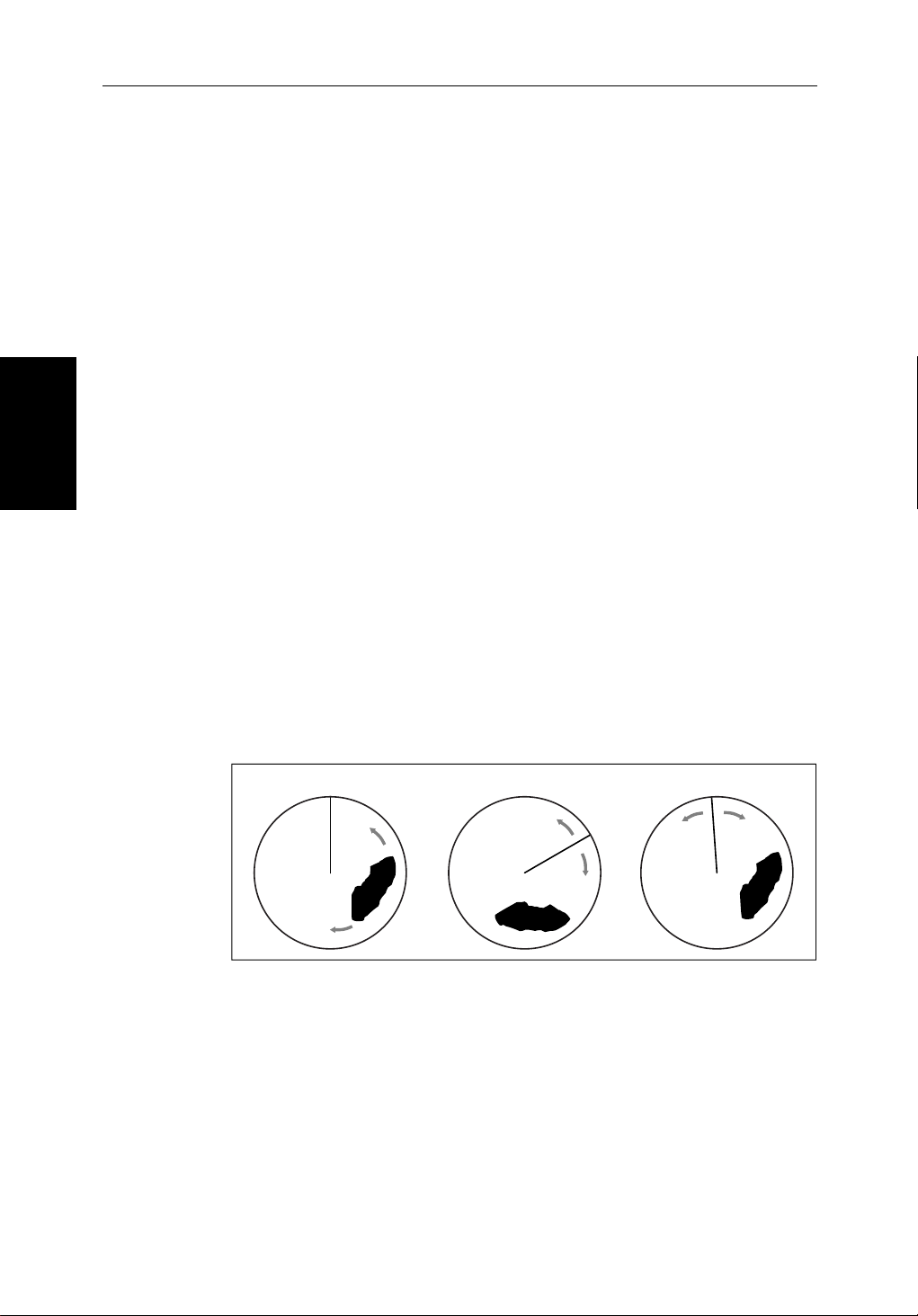
4-2 hsb
4.2 Changing the Heading Mode
Theradarpictureisnormallyshownwithyourvessel ’s dead ahead bearing
straightup,asindicatedbytheShip’sHeadingMarkerat0°relativebear ing.
ThisistheHeadUporientation.
Ifheadinginformationisavailabl evia a SeaTalkorNMEAconnection,you
canchooseadifferentheadin gmode. In Course Up and North Up mode you
canalsoselectrelativeor true motion.
2
PLUS Series Color LCD Display
Heading Mode
Changing the
Relativemotionisthedefaultfortheradar display.Inrelati vemotion your
ownship’ sposition remains fixed onthe radarscreenandallradartarget s
moverelativetoyourownship.
Intruemotion,fixedradartar getsmaintainaconstantpositionon the screen,
whilstyourownshipmovesacrosstheradarimageattheappropriatespeed
andheading.Amap-likeimageisthusdispl ayed,withallmovingvessels
travellingintrueperspecti v eto each other and to fixed land masses.
Asyourship’s position approaches the edge of the screen,theradardisplayis
automaticallyresettoreveal the area ahead of your ship. You can manually
resetyourship’s position at any time by pressing the TRUE REL soft key twice.
Heading Modes
Theheadingmodesareasfollows:
True and Relative Motion
Head Up
North Up Course Up
D3988-1
Figure 4-1: Radar Heading Modes
• HeadUp:Theradarpictureisdisplayedwith the vessel’scurrent heading
upwards.Astheheadingchangesthepicturewill rotate.
• NorthUp:Theradarpictureisstabilizedand displayed with north
upwards.Asyouchangeheading,theship’s heading marker moves.
• CourseUp:The radarpictureisstabilizedand displayed with the cur-
rentlysele ctedcourseupwards.Asyou changeheading,the ship’sheading
markermoves.Ifyouselectanewcourse,thepicture resets to display the
newcourseupwards.
Page 99

Chapter 4: Integrated Radar Operations 4-3
ThereferenceusedfortheCourseUpdependson theinformationavailable.
Thefirstavailableinthefol lowinglistisused:
1. A locked heading(i.e.theheadingbeingusedbyanautopilo t)over a
SeaTalk connection
2. The headingatthetimeCourseUpwasselected
If1.isinuseandanewcourse(lockedheading)is selected, the picture
automaticallyrotatesto thenewCourseUp.
If2.isinuse,presstheHDG MODE soft keythenCOURSE UP to manually reset
theCourseUptothenewcourse.
Selecting the Heading and Motion Mode
PresstheHDG MODE default softkeytoobtainthefollowingdisplay, when
headinginformationisavailable:
Motion
True and Re la tive
HDG MODE
Thecurrentlyselected mode ishighlighted,andis indicatedintheradar status
bar(N-UP, C-UP or H-UP and TM or RM).
➤ Tochangetheheadi ngand motion mode:
1. PresstheHDG MODE default soft key.
2. Pressthesoftkeycorrespondingtothemodeyourequire.Theradarpicture
changestotheselectedmode.
3. PressENTER toclear the heading mode soft keys.Thecurrentorientation
is indicated in the status bar.
Note:TrueMotionisonlyavailableinCourseUpandNorthup mode.
Ifyoure-selectCourseUpwhenthisisalreadythe current mode, the Course
Upreferenceisreassessedaccording to the current data.
Effect on VRM/EBLs
VRM/EBLsdonotmoveon thescreen,unlessyouchangetherange,offsetthe
centre,orchangetheheadingmode.
COURSE UPNORTH UP
HEAD UP
TRUE REL
D3641-3
• InHeadUpmode,theVRM/EBLsarefixedwithrespecttotheship’s
headingmarker.
• InNorthUpmode,theVRM/EBLsarefixedwithrespectto North.
• InCourseUpmode,theVRM/EBLsarefixedwithrespecttotheselected
course.
Page 100

4-4 hsb
4.3 Using Marks
TheMarksfunctionallowsyouto placeamarkanywhere ontheradarpicture.
You can also move existing marksordeletethem.You should be aware that
radarmarksarenotthesameaschartwaypointsandcannotbe used in routes,
norcantheybetransferredtootherdispl ays.
Marksareplacedwiththedefaultmark symbol at either cursor or vessel
position.Ifyouwishtouseadif ferentsymbol,youcanchangethedefault
settingfromtheRADAR SET UP menu (see Section 7.4). Mark symbols are
Using Marks
alwaysdisplayedwithina circle.
Marksarestoredwiththeirlatitude,longitude and symbol; the informationis
retainedwhentheradaristurnedoff. Up to 100 marks can be stored in each
displayunit.
2
PLUS Series Color LCD Display
MARKS
MARKS
PLACE MRK
AT CURSOR
PLACE MRK
AT VESSEL
Note:WhenyouusetheMARKS key to access the Marks function,simply
pressthekeymomentarilyandreleaseit.Ifyouholditdownfortwoseconds,
thePathfinderRadarwill enter man overboard(MOB)mode,asdescribed in
Section 4.4.
TheMarksfunctionisonlyavailablewhen yourvessel’spositionis knownvia
theSeaTalk or NMEA connection.
Placing a Mark
➤ Toplaceamarksymbol:
1. PresstheMARKS key. The soft keys PLACE MRK AT CURSOR and PLACE
MRK AT VESSEL aredisplayed.
2. Toplace a mark at the cursor,positionthecursor at the required point. If
youaredisplayingthecursorpositionbox showing the lat/long position,
youcancheckthecoordinatesto place the mark accurately.
PressthePLACE MARK AT CURSOR softkey.The mark is placedusingthe
defaultsymbol.
3. Toplace a mark at the vessel position,pressPLACE MRK AT VESSEL.The
markisplacedusingthedefaultsymbol.
Note:IftheMarkdatabaseisfull,awarningmessageis displayed, with the
position(inlatitudeandlongitude)of the oldest mark.Youhavethefollowi ng
options:
i. Press the YES softkeytoreplacethisoldmarkwiththenewmark.
ii. Pressthe NO softkeytokeeptheoldmarkanddisplaythe next oldest
mark.Youcan keeppressingNO tostepthroughthemarkdatabaseuntil
amarkyouwishtoreplaceisdisplayed,and then press YES.
iii. Press CLEAR tokeepalltheexistingmarks,and cancel the new mark
placement.
 Loading...