

Raymarine LIFETAG SYSTEM User Manual

LifeTag System
Installation &
Commissioning Guide
Document reference: 87064-3
Date: July 2006

Raymarine and SeaTalk are trademarks of Raymarine plc
© Handbook contents copyright Raymarine plc

LifeTag System Installation & Commissioning Guide i
Important Information
WARNINGS: LIFETAG SYSTEM
1. The Raymarine LifeTag System is an auxiliary safety system,
intended ONLY to provide additional protection to the vessel's crew.
DO NOT rely solely on this system for crew safety; DO ensure that all
safety instructions and procedures are obeyed in accordance with local
requirements.
2. Failure to operate the LifeTag System in accordance with its
operating instructions may result in unreliable or reduced system
performance.
3. The operation of some medical electronic devices, such as hearing
aids and pacemakers, may be affected if a LifeTag or LifeTag Base
Station is used next to them. Observe the manufacturers'
recommendations for such devices.
CAUTION: LITHIUM BATTERIES
The LifeTag System Tags use non-rechargeable lithium batteries. Do not
attempt to recharge these batteries. Do not incinerate these batteries.
Ensure that these batteries are replaced with batteries of the same type
and check local regulations when disposing of spent batteries.
Incorrectly fitting batteries or using the wrong battery types may result
in unreliable or reduced system performance.
RF Energy
The LifeTag and LifeTag Base Station are low-power radio transceivers. When on, they intermittently
transmit RF energy (radio waves). The LifeTag and LifeTag Base Station are designed to comply with
the limits for RF energy exposure for the general population set by national authorities and
international health agencies, for example BS EN 50371:2002.
Intended Use
The LifeTag and LifeTag Base Station are intended as an aid to safety on leisure vessels and small
workboats.
Waste Electrical and Electronic (WEEE) Directive
The WEEE Directive requires the recycling of waste electrical and electronic equipment.
Whilst the WEEE Directive does not apply to some of Raymarine's products, we support its policy
and ask you to be aware of how to dispose of this product.
The crossed out wheelie bin symbol, illustrated above, and found on our products signifies that this
product should not be disposed of in general waste or landfill.
Please contact your local dealer, national distributor or Raymarine Technical Services for
information on product disposal.

ii LifeTag System Installation & Commissioning Guide
LifeTag Installation & Commissioning Guide 1
LifeTag Installation & Commissioning Guide
Getting Started
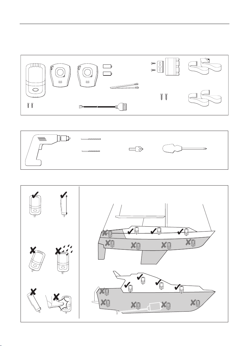
Base Station
Tags x2
No. 6 Self-tapping
screws x2
Figure 1 - Parts supplied
1
/8 inch (3.5 mm) drill
7
Power Drill
/
64
Figure 2 - Tools required
CR2 3V lithium
batteries x2
Buzzer, bracket and
Straps x2
fixing screws x2
Cable ties
SeaTalk cable
inch (2.5 mm) drill
Countersink bit
No. 8 Self-tapping
screws x2
Pozidriv screwdriver
Strap extensions x2
Fit Base Station as high up as possible, in a dry location
D8919-3
D9029-1
Figure 3 - Locating Base Station
D8955-2
2 LifeTag Installation & Commissioning Guide
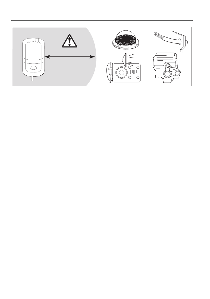
Min 3 ft 3 in (1m)
Figure 4 - Base Station separations
EMC Installation Guidelines
Raymarine equipment and accessories are designed to the best industry standards for use in the
recreational marine environment.
Their design and manufacture conforms to the appropriate Electromagnetic Compatibility (EMC)
regulations, but correct installation is required to ensure that performance is not compromised.
The guidelines given here describe the conditions for optimum EMC performance, but it is recognized that
it may not be possi ble to meet all of these cond itions in all situ ations. To ensure the best pos sible conditio ns
for EMC performance within the constraints imposed by any location, always ensure the maximum
separation possible between different items of electrical equipment.
For optimum EMC performance, it is recommended that wherever possible:
• Raymarine equipment and the cables connected to it are:
• At least 3 ft (1 m) from any equipment transmitting or cables carrying radio signals e.g. VHF radios,
cables and antennas. In the case of SSB radios, the distance should be increased to 7 ft (2 m).
• More than 7 ft (2 m) from the path of a radar beam. A radar beam can normally be assumed to
spread 20 degrees above and below the radiating element.
• The product is supplied from a separate battery from that used for engine start. Power supply voltages
below the minimum specified for a product, and starter motor transients, can cause the product to
reset. This will not damage the product, but may cause the loss of some information and may change
the operating mode.
• Raymarine specified cables are used. Cutting and rejoining these cables can compromise EMC performance and must be avoided unless doing so is detailed in the installation manual.
D9259-1
Suppression Ferrites
If a supplied cable is fitted with a suppression ferrite, the ferrite must not be removed , unless it is necessary
to facilitate installation. Any ferrite thus removed must be replaced in the original position immediately
installation is complete.
If additional suppression ferrites are required, use only ferrites supplied by Raymarine.
Connections to Other Equipment
If Raymarine equipment is to be connected to other equipment using a cable not supplied by Raymarine, a
Raymarine suppression ferrite MUST always be attached to the cable near the Raymarine unit.
 Loading...