

Raymarine Dragonfly-4, Dragonfly-5, Wi-Fish, Dragonfly-4Dragonfly-5 Installation And Operation Instructions Manual
Page 1

D
r a g o n fly-4
Dra g o n fly -5
Wi-F is h
TM
Installation and operation
instructions
English
Date: 12-2014
Document number: 81358-1-EN
© 2014 Raymarine UK Limited
R
elease 11
Page 2

Page 3

Trademarkandpatentsnotice
Raymarine,Tacktick,ClearPulse,Truzoom,HSB,SeaTalk,SeaTalk
hs
,SeaTalk
ng
,Micronet,Raytech,
GearUp,MarineShield,Seahawk,Autohelm,Automagic,andVisionalityareregisteredorclaimed
trademarksofRaymarineBelgium.
FLIR,DownVision,SideVision,Dragony,Instalert,InfraredEverywhere,andTheWorld’sSixth
SenseareregisteredorclaimedtrademarksofFLIRSystems,Inc.
Allothertrademarks,tradenames,orcompanynamesreferencedhereinareusedforidenticationonly
andarethepropertyoftheirrespectiveowners.
Thisproductisprotectedbypatents,designpatents,patentspending,ordesignpatentspending.
FairUseStatement
Youmayprintnomorethanthreecopiesofthismanualforyourownuse.Youmaynotmakeanyfurther
copiesordistributeorusethemanualinanyotherwayincludingwithoutlimitationexploitingthemanual
commerciallyorgivingorsellingcopiestothirdparties.
Softwareupdates
Checkthewebsitewww.raymarine.comforthelatestsoftwarereleasesforyourproduct.
Producthandbooks
ThelatestversionsofallEnglishandtranslatedhandbooksareavailabletodownloadinPDFformatfromthewebsite
www.raymarine.com.
Pleasecheckthewebsitetoensureyouhavethelatesthandbooks.
Copyright©2014RaymarineUKLtd.Allrightsreserved.
ENGLISH
Documentnumber:81358-1
Date:12-2014
Page 4

Page 5

Contents
Chapter1Importantinformation..........................7
TFTDisplays...............................................................8
Wateringress..............................................................8
Disclaimers.................................................................8
Memorycardsandchartcards.....................................8
EMCinstallationguidelines..........................................8
RFexposure...............................................................9
FCC............................................................................9
ComplianceStatement(Part15.19)..............................9
FCCInterferenceStatement(Part15.105(b))...............9
IndustryCanada..........................................................9
IndustryCanada(Français)..........................................9
Japaneseapprovals...................................................10
Thirdpartysoftwarelicenseagreements.....................10
Declarationofconformity............................................10
Pixeldefectpolicy......................................................10
Warrantypolicy..........................................................10
Warrantyregistration..................................................10
Productdisposal........................................................10
IMOandSOLAS........................................................10
Technicalaccuracy....................................................11
Chapter2Documentandproduct
information...........................................................13
2.1Documentinformation..........................................14
2.2Productoverview.................................................15
2.3CHIRPDownVision
TM
overview.............................16
2.4CHIRPSonaroverview.........................................17
Chapter3Planningtheinstallation...................19
3.1Installationchecklist.............................................20
3.2Partssupplied–DV,DVS,andProvariants...........20
3.3Partssupplied–5M.............................................21
3.4Partssupplied–Wi-Fish
TM
...................................21
3.5DownVision
™
transducercompatibility..................22
3.6T oolsrequiredforinstallation—Dragony-4DV
/4DVS/4Pro/5Pro...............................................23
3.7Toolsrequiredforinstallation—Dragony-5
M..............................................................................23
3.8Softwareupdates.................................................24
3.9Warningsandcautions.........................................24
3.10Selectingalocationforthetransducer.................25
3.11Cablerouting......................................................26
3.12Selectingalocationforthedisplay.......................26
3.13Installationprocess.............................................28
Chapter4Mounting.............................................29
4.1Mountingthetransommountbracket.....................30
4.2Mountingthetransducer.......................................30
4.3Removingthetransducer......................................31
4.4Mountingtheunit.................................................31
4.5T estingandadjustingthetransducer.....................32
4.6Finalizingthetransducermounting........................33
Chapter5Cablesandconnections....................35
5.1Generalcablingguidance.....................................36
5.2Connectionsoverview..........................................36
5.3Connectingthecable-DV,DVS,Proand
Wi-Fish
TM
.................................................................38
5.4Connectingthepowercable-5M.........................38
5.5Extensioncableconnection..................................40
Chapter6Wi-Fish
TM
............................................41
6.1Wi-Fishcontrols...................................................42
6.2Switchingtheunitonandoff.................................42
6.3Wi-Fish
TM
mobileapp..........................................43
6.4Wi-Fish
TM
initialsetup.........................................44
6.5DepthOffset........................................................44
6.6Switchingonthesimulator—Wi-Fish
TM
app...........................................................................45
6.7OpeningtheMicroSDcardreadercover................45
Chapter7Gettingstarted...................................47
7.1Controls—DV,DVS,ProandM..........................48
7.2Switchingtheunitonandoff.................................48
7.3Initialsetupprocedures........................................49
7.4Satellite-basednavigation.....................................50
7.5Checkingthesonarapplication.............................51
7.6CheckingtheDownVision
TM
application...............52
7.7Shortcutspage.....................................................52
7.8Applications.........................................................53
7.9Viewswitcher.......................................................54
7.10Memorycardsandchartcards............................55
7.11Learningresources.............................................56
Chapter8Fishnderapplications......................57
8.1DownVision
™
applicationoverview.......................58
8.2Sonarapplicationoverview...................................58
8.3Fishnderapplications'features............................60
8.4Fishnderapplications’controls............................60
8.5Zoom..................................................................61
8.6Range.................................................................62
8.7Scrolling..............................................................62
8.8A-Scopemode.....................................................63
8.9DisplayOptions....................................................63
8.10Colors...............................................................64
8.11Sensitivityadjustments.......................................65
8.12DVSystemsettingsmenuoptions.......................66
Chapter9Chartapplication................................67
9.1Chartapplicationoverview....................................68
9.2Electronicchartsoverview....................................69
9.3Chartapplicationcontrols.....................................72
9.4Waypointsoverview.............................................73
9.5Tracks.................................................................79
9.6ImportandExport................................................81
9.7Waypointsandtracksstoragecapacity..................82
9.8Navigation...........................................................82
5
Page 6

9.9Chartsettingsmenu—cartography
compatibility..............................................................83
9.10Chartselection...................................................84
9.11ChartDetail........................................................84
9.12Highresolutionbathymetry.................................85
9.13Chartorientation................................................85
9.14T extandSymbolsize..........................................86
9.15Boatposition......................................................87
9.16Communitylayer................................................87
9.17Sonarlogging.....................................................88
9.18COGVector.......................................................88
9.19DeepWater.......................................................89
9.20Chartobjects.....................................................89
9.215MSystemsettingsmenu..................................90
Chapter10Mobileapplications..........................91
10.1Wi-Fish
TM
mobileapp.........................................92
10.2ConnectingWi-Fi—Prodisplays........................92
Chapter11Tools&Settings...............................93
11.1SystemSettingsmenu........................................94
11.2Alarms.............................................................100
11.3Backupandreset.............................................103
11.4Wi-FiSettings...................................................105
Chapter12Maintenance...................................107
12.1Serviceandmaintenance.................................108
12.2Productcleaning..............................................108
12.3Transducercleaning.........................................109
Chapter13Troubleshooting..............................111
13.1Troubleshooting................................................112
13.2Poweruptroubleshooting..................................113
13.3GPStroubleshooting.........................................114
13.4Sonar/DownVisiontroubleshooting...................115
13.5Miscellaneoustroubleshooting...........................117
Chapter14Technicalsupport..........................119
14.1Raymarinecustomersupport............................120
14.2Learningresources...........................................120
Chapter15Technicalspecication..................121
15.1T echnicalspecication......................................122
Chapter16Sparesandaccessories................125
16.1Spares&Accessories......................................126
6
Dragony-4/Dragony-5/WiFish
Page 7

Chapter1:Importantinformation
Warning:Productinstallationand
operation
Thisproductmustbeinstalledand
operatedinaccordancewiththe
instructionsprovided.Failuretodoso
couldresultinpersonalinjury,damage
toyourvesseland/orpoorproduct
performance.
Warning:Ensuresafenavigation
Thisproductisintendedonlyasanaid
tonavigationandmustneverbeused
inpreferencetosoundnavigational
judgment.Onlyofcialgovernment
chartsandnoticestomarinerscontainall
thecurrentinformationneededforsafe
navigation,andthecaptainisresponsible
fortheirprudentuse.Itistheuser’s
responsibilitytouseofcialgovernment
charts,noticestomariners,cautionand
propernavigationalskillwhenoperating
thisoranyotherRaymarineproduct.
Warning:Potentialignitionsource
ThisproductisNOTapprovedforusein
hazardous/ammableatmospheres.Do
NOTinstallinahazardous/ammable
atmosphere(suchasinanengineroom
ornearfueltanks).
Warning:12Voltdconly
Thisproductmustonlybeconnectedtoa
12voltdcpowersource.
Warning:Highvoltages
Thisproductmaycontainhighvoltages.
DoNOTremoveanycoversorotherwise
attempttoaccessinternalcomponents,
unlessspecicallyinstructedinthe
documentationprovided.
Warning:Powersupplyvoltage
Connectingthisproducttoavoltage
supplygreaterthanthespecied
maximumratingmaycausepermanent
damagetotheunit.RefertotheTechnical
specicationsectionforvoltagerating.
Warning:Productgrounding
Beforeapplyingpowertothisproduct,
ensureithasbeencorrectlygrounded,in
accordancewiththeinstructionsprovided.
Warning:Switchoffpowersupply
Ensurethevessel’spowersupplyis
switchedOFFbeforestartingtoinstallthis
product.DoNOTconnectordisconnect
equipmentwiththepowerswitchedon,
unlessinstructedinthisdocument.
Warning:FCCWarning(Part15.21)
Changesormodicationstothis
equipmentnotexpresslyapprovedin
writingbyRaymarineIncorporatedcould
violatecompliancewithFCCrulesand
voidtheuser’sauthoritytooperatethe
equipment.
Caution:Serviceandmaintenance
Thisproductcontainsnouserserviceable
components.Pleasereferallmaintenance
andrepairtoauthorizedRaymarine
dealers.Unauthorizedrepairmayaffect
yourwarranty.
Caution:Transducercable
•DoNOTcut,shorten,orsplicethe
transducercable.
•DoNOTremovetheconnector.
Ifthecableiscut,itcannotberepaired.
Cuttingthecablewillalsovoidthe
warranty.
Caution:Powersupplyprotection
Wheninstallingthisproductensurethe
powersourceisadequatelyprotected
bymeansofasuitably-ratedfuseor
automaticcircuitbreaker.
Caution:Careofchartandmemory
cards
Toavoidirreparabledamagetoand/or
lossofdatafromchartandmemorycards:
•DONOTsavedataorlestoacard
containingcartographyasthecharts
maybeoverwritten.
•Ensurethatchartandmemorycards
arettedthecorrectwayaround.DO
NOTtrytoforceacardintoposition.
•DONOTuseametallicinstrumentsuch
asascrewdriverorplierstoinsertor
removeachartormemorycard.
Caution:Ensurecardreaderdoor
issecurelyclosed
Topreventwateringressandconsequent
damagetotheproduct,ensurethatthe
cardreaderdoorisrmlyclosed.
Importantinformation
7
Page 8

Caution:Productcleaning
Whencleaningproducts:
•Ifyourproductincludesadisplay
screen,doNOTwipethescreenwith
adrycloth,asthiscouldscratchthe
screencoating.
•DoNOTuseabrasive,oracidor
ammoniabasedproducts.
•DoNOTuseajetwash.
TFTDisplays
Thecolorsofthedisplaymayseemtovarywhen
viewedagainstacoloredbackgroundorincolored
light.Thisisaperfectlynormaleffectthatcan
beseenwithallcolorThinFilmTransistor(TFT)
displays.
Wateringress
Wateringressdisclaimer
Althoughthewaterproofratingcapacityofthis
productmeetsthestatedIPXstandard(refertothe
product’sTechnicalSpecication),waterintrusion
andsubsequentequipmentfailuremayoccurifthe
productissubjectedtocommercialhigh-pressure
washing.Raymarinewillnotwarrantproducts
subjectedtohigh-pressurewashing.
Disclaimers
Thisproduct(includingtheelectroniccharts)is
intendedtobeusedonlyasanaidtonavigation.It
isdesignedtofacilitateuseofofcialgovernment
charts,notreplacethem.Onlyofcialgovernment
chartsandnoticestomarinerscontainallthecurrent
informationneededforsafenavigation,andthe
captainisresponsiblefortheirprudentuse.Itis
theuser’sresponsibilitytouseofcialgovernment
charts,noticestomariners,cautionandproper
navigationalskillwhenoperatingthisoranyother
Raymarineproduct.Thisproductsupportselectronic
chartsprovidedbythirdpartydatasupplierswhich
maybeembeddedorstoredonmemorycard.Use
ofsuchchartsissubjecttothesupplier’sEnd-User
LicenceAgreementincludedinthedocumentation
forthisproductorsuppliedwiththememorycard
(asapplicable).
Raymarinedoesnotwarrantthatthisproductis
error-freeorthatitiscompatiblewithproducts
manufacturedbyanypersonorentityotherthan
Raymarine.
Thisproductusesdigitalchartdata,andelectronic
informationfromtheGlobalPositioningSystem
(GPS)whichmaycontainerrors.Raymarinedoes
notwarranttheaccuracyofsuchinformationand
youareadvisedthaterrorsinsuchinformationmay
causetheproducttomalfunction.Raymarineisnot
responsiblefordamagesorinjuriescausedbyyour
useorinabilitytousetheproduct,bytheinteraction
oftheproductwithproductsmanufacturedbyothers,
orbyerrorsinchartdataorinformationutilizedby
theproductandsuppliedbythirdparties.
Memorycardsandchartcards
MicroSDmemorycardscanbeusedtobackup/
archivedata(e.g.Waypoint,andTracks).Once
dataisbackeduptoamemorycardolddatacan
bedeletedfromthesystem,creatingcapacityfor
newdata.Thearchiveddatacanberetrievedatany
time.Chartcardsprovideadditionalorupgraded
cartography.
Itisrecommendedthatyourdataisbackeduptoa
memorycardonaregularbasis.DoNOTsavedata
toamemorycardcontainingcartography.
Compatiblecards
ThefollowingtypesofMicroSDcardsarecompatible
withyourdisplay:
•MicroSecureDigitalStandard-Capacity
(MicroSDSC)
•MicroSecureDigitalHigh-Capacity(MicroSDHC)
Note:
•Themaximumsupportedmemorycardcapacity
is32GB.
•MicroSDcardsmustbeformattedtouseeither
theFA TorFA T32lesystemformattoenable
usewithyourMFD.
Speedclassrating
Forbestperformanceitisrecommendedthatyou
useClass10orUHS(UltraHighSpeed)class
memorycards.
Chartcards
Yourproductispre-loadedwithelectroniccharts
(worldwidebasemap).Ifyouwishtousedifferent
chartdata,youcaninsertcompatiblechartcardsinto
theunit'smemorycardreader.
Usebrandedchartcardsandmemorycards
Whenarchivingdataorcreatinganelectronicchart
card,Raymarinerecommendstheuseofquality
brandedmemorycards.Somebrandsofmemory
cardmaynotworkinyourunit.Pleasecontact
customersupportforalistofrecommendedcards.
EMCinstallationguidelines
Raymarineequipmentandaccessoriesconformto
theappropriateElectromagneticCompatibility(EMC)
regulations,tominimizeelectromagneticinterference
betweenequipmentandminimizetheeffectsuch
interferencecouldhaveontheperformanceofyour
system
CorrectinstallationisrequiredtoensurethatEMC
performanceisnotcompromised.
8
Dragony-4/Dragony-5/WiFish
Page 9

Note:InareasofextremeEMCinterference,
someslightinterferencemaybenoticedonthe
product.Wherethisoccurstheproductandthe
sourceoftheinterferenceshouldbeseparatedby
agreaterdistance.
ForoptimumEMCperformancewerecommend
thatwhereverpossible:
•Raymarineequipmentandcablesconnectedto
itare:
–Atleast1m(3ft)fromanyequipment
transmittingorcablescarryingradiosignalse.g.
VHFradios,cablesandantennas.Inthecase
ofSSBradios,thedistanceshouldbeincreased
to7ft(2m).
–Morethan2m(7ft)fromthepathofaradar
beam.Aradarbeamcannormallybeassumed
tospread20degreesaboveandbelowthe
radiatingelement.
•Theproductissuppliedfromaseparatebattery
fromthatusedforenginestart.Thisisimportantto
preventerraticbehavioranddatalosswhichcan
occuriftheenginestartdoesnothaveaseparate
battery.
•Raymarinespeciedcablesareused.
•Cablesarenotcutorextended,unlessdoingsois
detailedintheinstallationmanual.
Note:Whereconstraintsontheinstallation
preventanyoftheaboverecommendations,
alwaysensurethemaximumpossibleseparation
betweendifferentitemsofelectricalequipment,to
providethebestconditionsforEMCperformance
throughouttheinstallation
RFexposure
ThisequipmentcomplieswithFCC/ICRFexposure
limitsforgeneralpopulation/uncontrolledexposure.
ThewirelessLAN/Bluetoothantennaismounted
behindthefrontfaciaofthedisplay.Thisequipment
shouldbeinstalledandoperatedwithaminimum
distanceof1cm(0.39in)betweenthedeviceand
thebody.Thistransmittermustnotbeco-located
oroperatinginconjunctionwithanyotherantenna
ortransmitter,exceptinaccordancewithFCC
multi-transmitterproductprocedures.
FCC
ComplianceStatement(Part15.19)
ThisdevicecomplieswithPart15oftheFCCRules.
Operationissubjecttothefollowingtwoconditions:
1.Thisdevicemaynotcauseharmfulinterference.
2.Thisdevicemustacceptanyinterference
received,includinginterferencethatmaycause
undesiredoperation.
FCCInterferenceStatement(Part
15.105(b))
Thisequipmenthasbeentestedandfoundtocomply
withthelimitsforaClassBdigitaldevice,pursuant
toPart15oftheFCCRules.
Theselimitsaredesignedtoprovidereasonable
protectionagainstharmfulinterferenceina
residentialinstallation.Thisequipmentgenerates,
uses,andcanradiateradiofrequencyenergyand,
ifnotinstalledandusedinaccordancewiththe
instructions,maycauseharmfulinterferencetoradio
communications.However,thereisnoguarantee
thatinterferencewillnotoccurinaparticular
installation.Ifthisequipmentdoescauseharmful
interferencetoradioortelevisionreception,which
canbedeterminedbyturningtheequipmentoff
andon,theuserisencouragedtotrytocorrectthe
interferencebyoneofthefollowingmeasures:
1.Reorientorrelocatethereceivingantenna.
2.Increasetheseparationbetweentheequipment
andreceiver.
3.Connecttheequipmentintoanoutletona
circuitdifferentfromthattowhichthereceiver
isconnected.
4.Consultthedealeroranexperiencedradio/TV
technicianforhelp.
IndustryCanada
ThisdevicecomplieswithIndustryCanada
License-exemptRSSstandard(s).
Operationissubjecttothefollowingtwoconditions:
1.Thisdevicemaynotcauseinterference;and
2.Thisdevicemustacceptanyinterference,
includinginterferencethatmaycauseundesired
operationofthedevice.
ThisClassBdigitalapparatuscomplieswith
CanadianICES-003.
IndustryCanada(Français)
Cetappareilestconformeauxnormesd'exemption
delicenceRSSd'IndustryCanada.
Sonfonctionnementestsoumisauxdeuxconditions
suivantes:
1.cetappareilnedoitpascauserd'interférence,et
2.cetappareildoitacceptertouteinterférence,
notammentlesinterférencesquipeuventaffecter
sonfonctionnement.
CetappareilnumériquedelaclasseBestconforme
àlanormeNMB-003duCanada.
Importantinformation
9
Page 10

Japaneseapprovals
Inthefrequencybandusedforthisdevice,campusradio
stations(radiosstationsthatrequirealicense)andspecied
lowpowerradiostations(radiostationsthatdonotrequire
license)formobileidenticationandamateurradiostations
(radiostationsthatrequirelicense)usedinindustriessuchas
microwaveovens,scientic,medicalequipmentdevicesand
productionlineofotherfactoriesarealsobeingoperated.
1.Beforeusingthisdevice,pleasemakesurethatcampus
radiostationsandspeciedlowpowerradiostationsfor
mobileidenticationandamateurradiostationsarenot
beingoperatednearby.
2.Incasethereisanycaseofharmfulinterferenceto
campusradiostationsformobileidenticationcausedby
thisdevice,pleaseimmediatelychangethefrequency
usedorstopthetransmissionofradiowavesandthen
consultaboutthemeasurestoavoidinterference(for
example,theinstallationofpartitions)throughthecontact
informationbelow.
3.Besides,whenintrouble,suchaswhenthereisany
caseofharmfulinterferencetospeciedlowpower
radiostationsformobileidenticationoramateurradio
stationscausedbythisdevice,pleaseconsultthrough
thefollowingcontactinformation.
Contactinformation:Pleasecontactyourlocalauthorized
Raymarinedealer.
Thirdpartysoftwarelicense
agreements
Thisproductissubjecttocertainthirdpartysoftware
licenseagreementsaslistedbelow:
•GNU—LGPL/GPL
•JPEGlibraries
•OpenSSL
•FreeType
Thelicenseagreementsfortheabovecanbefound
onthewebsitewww .raymarine.comandonthe
accompanyingdocumentationCDifsupplied.
Declarationofconformity
RaymarineUKLtd.declaresthatthisproductis
compliantwiththeessentialrequirementsofR&TTE
directive1999/5/EC.
TheoriginalDeclarationofConformitycerticate
maybeviewedontherelevantproductpageat
www.raymarine.com.
Pixeldefectpolicy
IncommonwithallTFTunits,thescreenmayexhibit
afewwrongly-illuminated(“dead”)pixels.These
mayappearasblackpixelsinalightareaofthe
screenorascoloredpixelsinblackareas.
IfyourdisplayexhibitsMOREthanthenumber
ofwrongly-illuminatedpixelsallowed(refertothe
producttechnicalspecicationfordetails),please
contactyourlocalRaymarineservicecenterfor
furtheradvice.
Warrantypolicy
Yourproductiswarrantedtobefreefromdefectsin
materialsandworkmanshipforaperiodof1year
fromthedateofrstpurchaseoftheproductor,if
installedonanewboat,thedateofrstboatdelivery
totheOriginalCustomer(pleaseretainproofof
purchaseincaseyouneedtoclaim).
ThefulldetailsoftheLimitedWarrantyPolicy
andregistrationprocessareavailableonlineat:
www.raymarine.com/warranty-dragony.
IfyoudonothaveaccesstotheInternet,please
phonetherelevantnumberbelowtoobtainwarranty
policyinformation:
IntheUSA:
•Tel:+16033247900
•TollFree:+18005395539
IntheUK,Europe,theMiddleEast,orFarEast:
•Tel:+44(0)1329246777
Warrantyregistration
ToregisteryourRaymarineproductownership,
pleasevisitwww.raymarine.comandregisteronline.
Itisimportantthatyouregisteryourproductto
receivefullwarrantybenets.Y ourunitpackage
includesabarcodelabelindicatingtheserialnumber
oftheunit.Y ouwillneedthisserialnumberwhen
registeringyourproductonline.Y oushouldretain
thelabelforfuturereference.
Productdisposal
Disposeofthisproductinaccordancewiththe
WEEEDirective.
TheWasteElectricalandElectronicEquipment
(WEEE)Directiverequirestherecyclingofwaste
electricalandelectronicequipment.Whilstthe
WEEEDirectivedoesnotapplytosomeRaymarine
products,wesupportitspolicyandaskyoutobe
awareofhowtodisposeofthisproduct.
IMOandSOLAS
Theequipmentdescribedwithinthisdocument
isintendedforuseonleisuremarineboatsand
workboatsNOTcoveredbyInternationalMaritime
Organization(IMO)andSafetyofLifeatSea
(SOLAS)CarriageRegulations.
10
Dragony-4/Dragony-5/WiFish
Page 11

Technicalaccuracy
Tothebestofourknowledge,theinformationinthis
documentwascorrectatthetimeitwasproduced.
However,Raymarinecannotacceptliabilityforany
inaccuraciesoromissionsitmaycontain.Inaddition,
ourpolicyofcontinuousproductimprovementmay
changespecicationswithoutnotice.Asaresult,
Raymarinecannotacceptliabilityforanydifferences
betweentheproductandthisdocument.Please
checktheRaymarinewebsite(www.raymarine.com)
toensureyouhavethemostup-to-dateversion(s)of
thedocumentationforyourproduct.
Importantinformation
11
Page 12

12
Dragony-4/Dragony-5/WiFish
Page 13

Chapter2:Documentandproductinformation
Chaptercontents
•2.1Documentinformationonpage14
•2.2Productoverviewonpage15
•2.3CHIRPDownVision
TM
overviewonpage16
•2.4CHIRPSonaroverviewonpage17
Documentandproductinformation
13
Page 14
2.1Documentinformation
Thisdocumentcontainsimportantinformation
relatedtotheinstallationofyourRaymarineproduct.
Thedocumentincludesinformationtohelpyou:
•planyourinstallationandensureyouhaveallthe
necessaryequipment;
•installandconnectyourproductaspartofawider
systemofconnectedmarineelectronics;
•troubleshootproblemsandobtaintechnical
supportifrequired.
ThisandotherRaymarineproductdocuments
areavailabletodownloadinPDFformatfrom
www.raymarine.com.
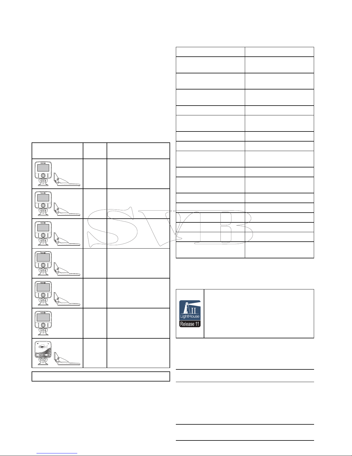
Applicableproducts
Thisdocumentisapplicabletothefollowingproducts:
Part
numberDescription
E70291
Dragony-4DV
Standalonesinglechannel
Fishnderdisplaywith
transducer
E70292
Dragony-4DVS
Standalonedualchannel
Fishnderdisplaywith
transducer
E70294
Dragony-4Pro
Standalonedualchannel
Fishnder/Chartplotter
displaywithtransducer
E70306
Dragony-5DVS
Standalonedualchannel
Fishnderdisplaywith
transducer
E70293
Dragony-5Pro
Standalonedualchannel
Fishnder/Chartplotter
displaywithtransducer
E70295
Dragony-5MStandalone
Chartplotterdisplay
E70290
Wi-Fish
TM
Standalone
singlechannelWi-Fisonar
module
Note:Dragony
®
productsarenotnetworkable.
Applicablechapters
Somechaptersinthismanualareonlyapplicable
tocertainproductvariants.Thetablebelowshows
whichchaptersareapplicabletoeachproduct
variant.
ChapterVariant
Chapter1Important
information
All
Chapter2Documentand
productinformation
All
Chapter3Planningthe
installation
All
Chapter4Mounting
All
Chapter5Cablesand
connections
All
Chapter6Wi-Fish
TM
Wi-Fish
TM
Chapter7GettingstartedDV,DVS,MandPro
Chapter8Fishnder
applications
DV,DVSandPro
Chapter9Chartapplication
MandPro
Chapter10Mobile
applications
Pro
Chapter11Tools&SettingsDVSandPro
Chapter12Maintenance
All
Chapter13Troubleshooting
All
Chapter14T echnicalsupport
All
15.1T echnicalspecication
All
Chapter16Sparesand
accessories
All
Softwarerevision
Raymarineregularlyupdatesproductsoftwareto
addnewfeaturesandimproveexistingfunctionality .
Release 11
Thishandbookcoverssoftwareversion—
LightHouseIIRelease11.
PleaserefertotheSoftwareReleasessection
fordetailsonsoftwarereleases.
ChecktheRaymarinewebsitetoensureyou
havethelatestsoftwareandusermanuals.
www.raymarine.com.
Productdocumentation
Thefollowingdocumentationisapplicabletoyour
product:
DescriptionPartnumber
Dragony-4,Dragony-5andWi-Fish
TM
installationandoperationinstructions
Installationandoperationalinstructions
fortheDragony–4,Dragony-5and
Wi-Fish
TM
displaysandtheCPT-DVand
CPT-DVStransducer
81358
CPT-DVandCPT-DVSTransommount
transducermountingtemplate
87238
14
Dragony-4/Dragony-5/WiFish
Page 15

Documentconventions
Thefollowingconventionsareusedthroughoutthis
handbook.
Select
Theterm‘Select’isusedtodescribetheactionof
usingtheproduct’sdirectionalcontrolstohighlight
anitemandthenpressingtheOKbuttontoconrm
theselection.
Directionalcontrols
Theterm‘Directionalcontrols’isusedtodescribe
theUp,Down,LeftandRightcontrols.
Documentillustrations
Yourproductmaydifferslightlyfromthatshown
intheillustrationsinthisdocument,dependingon
productvariantanddateofmanufacture.
Allimagesareprovidedforillustrationpurposesonly.
UsermanualsPrintShop
RaymarineprovidesaPrintShopservice,enabling
youtopurchaseahigh-quality,professionally-printed
manualforyourRaymarineproduct.
Printedmanualsareidealforkeepingonboardyour
vessel,asausefulsourceofreferencewhenever
youneedassistancewithyourRaymarineproduct.
Visithttp://www.raymarine.co.uk/view/?id=5175to
orderaprintedmanual,delivereddirectlytoyour
door.
ForfurtherinformationaboutthePrintShop,
pleasevisitthePrintShopFAQpages:
http://www.raymarine.co.uk/view/?id=5751.
Note:
•Acceptedmethodsofpaymentforprinted
manualsarecreditcardsandPayPal.
•Printedmanualscanbeshippedworldwide.
•FurthermanualswillbeaddedtothePrintShop
overthecomingmonthsforbothnewandlegacy
products.
•Raymarineusermanualsarealsoavailableto
downloadfree-of-chargefromtheRaymarine
website,inthepopularPDFformat.ThesePDF
lescanbeviewedonaPC/laptop,tablet,
smartphone,oronthelatestgenerationof
Raymarinemultifunctiondisplays.
2.2Productoverview
Dragony
®
productsarestandaloneFishnderand/
orChartplotterproducts.
D13240-1
Thefollowingproductsareavailable:
ProductFeatures
Wi-Fish
TM
•1xCHIRPDownVision
™
channel
•SuppliedwithCPT-DV(CHIRP
DownVision
™
andtemperaturetransom
mounttransducer
•Built-inWi-Fi(displayonAndroid4and
iOS7compatiblesmartdevices)
•Easyballandsocketdisplaymounting
Dragony-4DV
•4.3’BrightallweatherLEDdisplay
•1xCHIRPDownVision
™
channel
•SuppliedwithCPT-DV(CHIRP
DownVision
™
andtemperaturetransom
mounttransducer
•Easyballandsocketdisplaymounting
Dragony-4
DVS
•4.3’BrightallweatherLEDdisplay
•DualchannelCHIRPDownVision
™
and
CHIRPSonarchannels.
•SuppliedwithCPT-DVS(Combined
CHIRPDownVision
™
,CHIRPsonar
andtemperaturetransommount
transducer
•Easyballandsocketdisplaymounting
Dragony-4
Pro
•4.3’BrightallweatherLEDdisplay
•DualchannelCHIRPDownVision
™
and
CHIRPSonarchannels.
•SuppliedwithCPT-DVS(Combined
CHIRPDownVision
™
,CHIRPsonar
andtemperaturetransommount
transducer
•Easyballandsocketdisplaymounting
•Built-inWi-Fi(displayonAndroid4and
iOS7compatiblesmartdevices)
•Built-inGNSS(GPS/GLONASS)
receiver
Documentandproductinformation
15
Page 16

ProductFeatures
•CompatiblewithLightHousecharts,
Navionics
®
andC-Mapchartsby
Jeppesen
®
Dragony-5
DVS
•5’BrightallweatherLEDdisplay
•DualchannelCHIRPDownVision
™
and
CHIRPSonarchannels.
•SuppliedwithCPT-DVS(Combined
CHIRPDownVision
™
,CHIRPsonar
andtemperaturetransommount
transducer
•Easyballandsocketdisplaymounting
Dragony-5
Pro
•5’BrightallweatherLEDdisplay
•DualchannelCHIRPDownVision
™
and
CHIRPSonarchannels.
•SuppliedwithCPT-DVS(Combined
CHIRPDownVision
™
,CHIRPsonar
andtemperaturetransommount
transducer
•Easyballandsocketdisplaymounting
•Built-inWi-Fi(displayonAndroid4and
iOS7compatiblesmartdevices)
•Built-inGNSS(GPS/GLONASS)
receiver
•CompatiblewithLightHousecharts,
Navionics
®
andC-Mapchartsby
Jeppesen
®
Dragony-5M
•5’BrightallweatherLEDdisplay
•Easyballandsocketdisplaymounting
•Built-inGNSS(GPS/GLONASS)
receiver
•CompatiblewithLightHousecharts,
Navionics
®
andC-Mapchartsby
Jeppesen
®
2.3CHIRPDownVision
TM
overview
DownVision
TM
producesawide–angleside-to-side
beamandathinfore-to-aftbeam.Thecoverageof
theDownVision
TM
beamisawatercolumndirectly
beneathandtothesidesofthevessel.
DownVision
TM
beam
D12777-2
DownVision
TM
iseffectiveatlowervesselspeeds.In
deeperwaterstheCHIRPbandwidthisautomatically
optimizedtoimprovebottomlockandthedetectionof
movingobjects(e.g.sh)inthewiderwatercolumn.
Thewide,thinbeamproducescleartargetreturns.
TheuseofCHIRPprocessingandahigheroperating
frequencyprovideamoredetailedimage,making
iteasiertoidentifybottomstructuresaroundwhich
shmayreside.
CHIRPDownVision
TM
screenexample
16
Dragony-4/Dragony-5/WiFish
Page 17

2.4CHIRPSonaroverview
CHIRPsonarproducesaconicalshapedbeam,the
coverageoftheconicalbeamisthewatercolumn
directlybeneaththevessel
Conicalbeam
D12784-2
Sonariseffectiveatarangeofspeeds.Indeeper
waterstheCHIRPbandwidthisautomatically
optimizedtoimprovebottomlockandthedetection
ofmovingobjects(e.g.sh)inthewiderwater
column.
CHIRPsonarscreenexample
Documentandproductinformation
17
Page 18

18
Dragony-4/Dragony-5/WiFish
Page 19

Chapter3:Planningtheinstallation
Chaptercontents
•3.1Installationchecklistonpage20
•3.2Partssupplied–DV,DVS,andProvariantsonpage20
•3.3Partssupplied–5Monpage21
•3.4Partssupplied–Wi-Fish
TM
onpage21
•3.5DownVision
™
transducercompatibilityonpage22
•3.6Toolsrequiredforinstallation—Dragony-4DV/4DVS/4Pro/5Proonpage23
•3.7Toolsrequiredforinstallation—Dragony-5Monpage23
•3.8Softwareupdatesonpage24
•3.9Warningsandcautionsonpage24
•3.10Selectingalocationforthetransduceronpage25
•3.11Cableroutingonpage26
•3.12Selectingalocationforthedisplayonpage26
•3.13Installationprocessonpage28
Planningtheinstallation
19
Page 20

3.1Installationchecklist
Installationincludesthefollowingactivities:
InstallationTask
1Planyoursystem.
2
Obtainallrequiredequipmentandtools.
3
Siteallequipment.
4Routeallcables.
5
Drillcableandmountingholes.
6Makeallconnectionsintoequipment.
7
Secureallequipmentinplace.
8Poweronandtestthesystem.
3.2Partssupplied–DV,DVS,andPro
variants
Thepartssuppliedwithyourproductareshown
below.
D13178-1
1
9
10
16
6
7
8
2
3
4
5
17
x3
x3
x3
x3
111812 13 14 15
1.Displayunit
2.Lockingcollar
3.Pivotball
4.M6Hexbolt
5.Displaybracketbase
6.3xM5pozi-drivebolt
7.3xM5washer
8.3xM5lockingnut
9.Ratchetarm
10.Mountingbracket
11.M5Hexratchetbolt
12.Ratchetplate
13.Compressionwasher
14.M5washer
15.M5lockingnut
16.3xSelftappingscrews
17.Documentation
18.Transducerwithcombinedpowercable
20
Dragony-4/Dragony-5/WiFish
Page 21

3.3Partssupplied–5M
Thepartssuppliedwithyourproductareshown
below.
D13179-1
1
9
10
6
7
8
2
3
4
5
x3
x3
x3
1.Displayunit
2.Lockingcollar
3.Pivotball
4.M6Hexbolt
5.Displaybracketbase
6.3xM5pozi-drivebolt
7.3xM5washer
8.3xM5lockingnut
9.Documentation
10.1.5m(4.9ft.)Powercable
3.4Partssupplied–Wi-Fish
TM
Thepartssuppliedwithyourproductareshown
below.
D13180-1
1
9
10
16
6
7
8
2
3
4
5
17
x3
x3
x3
x3
111812 13 14 15
1.Wi-Fish
TM
unit
2.Lockingcollar
3.Pivotball
4.M6Hexbolt
5.Unitbracketbase
6.3xM5pozi-drivebolt
7.3xM5washer
8.3xM5lockingnut
9.Ratchetarm
10.Mountingbracket
11.M5Hexratchetbolt
12.Ratchetplate
13.Compressionwasher
14.M5washer
15.M5lockingnut
16.3xSelftappingscrews
17.Documentation
18.Transducerwithcombinedpowercable
Planningtheinstallation
21
Page 22

3.5DownVision
™
transducer
compatibility
TransducerDescription
Compatible
displays
CPT-DV(R70373)Singlebeam
DownVision
TM
transducer(3
keywayconnector)
•DV
•Wi-Fish
CPT-DVS
(R70374)
Dualbeam
DownVision
TM
andSonar
transducer(3
keywayconnector)
•DVS
•Pro
•Updated
Dragony-6
•Updated
Dragony-7
•*Legacy
Dragony-6
•*LegacyDragony-7
•Updated
CPT-60
(A80195)
•Updated
CPT-70
(A80278)
•Updated
CPT-80
(A80279)
Dualbeam
DownVision
TM
andSonar
transducer(3
keywayconnector)
•DVS
•Pro
•Updated
Dragony-6
•Updated
Dragony-7
•*Legacy
Dragony-6
•*LegacyDragony-7
•LegacyCPT-60
(A80195)
•LegacyCPT-70
(A80278)
•LegacyCPT-80
(A80279)
Dualbeam
DownVision
TM
andSonar
transducer(1
keywayconnector)
•Legacy
Dragony-6
•LegacyDragony-7
•*DVS
•*Pro
Note:*Adaptorcablerequiredforconnection.
Note:
•ConnectingaCPT-DVtoaDVSoraProwill
preventtheSonarapplicationfromfunctioning.
•ConnectingaCPT-DVStoaDVoraorWi-Fish
willnotenabletheSonarapplication.
•TheMcannotbeconnectedtoatransducer.
Legacyandupdatedproducts
CurrentDragony-6,Dragony-7displaysand
CPT-60/CPT-70/CPT-80transducerdesignshave
beenmodiedtoincludetheimproved3keyway
connectors.
Thetablebelowidentiestheeffectivemanufacturing
datefortheimprovedkeywayconnectors.
Product
3keyway
introductiondate
3keyway
introduction
serialnumber
Dragony-6
display
January2015E700850150001
Dragony-7
display
November2014E702311140712
CPT-60
December2014A801951240023
CPT-70
February2015
TBC
CPT-80
February2015
TBC
22
Dragony-4/Dragony-5/WiFish
Page 23

3.6T oolsrequiredforinstallation—
Dragony-4DV/4DVS/4Pro/5Pro
1 3
5
2
4
6
D13176-1
1.Cordlessdrill
2.Pozi-drivescrewdriver
3.8mmwrench(spanner)
4.5mmHexwrench(allenkey)
5.4mmHexwrench(allenkey)
6.Drillbit
Youwillalsorequire:
•marinegradesealant
•awaterprooffuseholderand5Ainlinefuse.
•apaperclip(incaseyouneedtoremovethe
transducerfromthebracket.)
3.7T oolsrequiredforinstallation—
Dragony-5M
1 3
2
4 5
D13177-1
1.Cordlessdrill
2.Pozi-drivescrewdriver
3.8mmwrench(spanner)
4.5mmHexwrench(allenkey)
5.Drillbit
Youwillalsorequire:
•awaterprooffuseholderand5Ainlinefuse.
Planningtheinstallation
23
Page 24

3.8Softwareupdates
Thesoftwarerunningontheproductcanbeupdated.
•Raymarineperiodicallyreleasessoftwareupdates
toimproveproductperformanceandaddnew
features.
•Y oucanupdatethesoftwareforyourproductusing
aconnectedandcompatiblemultifunctiondisplay.
•Refertowww.raymarine.com/software/forthe
latestsoftwareupdatesandthesoftwareupdate
procedureforyourproduct.
•Ifindoubtastothecorrectprocedureforupdating
yourproductsoftware,refertoyourdealeror
Raymarinetechnicalsupport.
Caution:Downloadingsoftware
updates
Thesoftwareupdateprocessiscarried
outatyourownrisk.Beforeinitiatingthe
updateprocessensureyouhavebacked
upanyimportantles.
Ensurethattheunithasareliablepower
supplyandthattheupdateprocessisnot
interrupted.
Damagecausedbyincompleteupdates
arenotcoveredbyRaymarinewarranty.
Bydownloadingthesoftwareupdate
package,youagreetotheseterms.
3.9Warningsandcautions
Important:Beforeproceeding,ensurethatyou
havereadandunderstoodthewarningsand
cautionsprovidedintheChapter1Important
informationsectionofthisdocument.
24
Dragony-4/Dragony-5/WiFish
Page 25

3.10Selectingalocationforthe
transducer
Thisproductissuppliedwithatransommount
transducer.Theguidelinesbelowshouldbefollowed
whenselectingalocationforthetransducer.
Note:Thetransducerisnotsuitableformounting
onvesselswherethetransomisaftofthe
propeller(s).
Forbestperformancethetransducermustbe
installedinalocationwiththeleastturbulenceand
aeration.Themosteffectivewaytodeterminethis
isbycheckingthewaterowaroundthetransom
whilstunderway.
D13184-1
•Mountclosetothekeel(centerline),inaposition
wherethetransducerelementwillbefully
submergedwhenthevesselisplaningandturning.
•Mountasuitabledistancefromthepropeller(s)to
avoidwake.
•Forclockwiserotatingpropellers,mount
thetransduceronthestarboardside,for
counter-clockwise,mountontheportside.
•Onatwinenginevesselmountthetransducer
betweentheengines.
•Turbulencecanbecausedbyanumberofother
factorssuchassteps(1),ribs(2),rowsofrivets
(3)andstrakes(4).Theturbulenceappearsaft
oftheselocations.
1
2
4
3
D1263 6-1
•Airtrappedunderthefrontofthevesselcantravel
underthehullandappearasaerationaft.
•Ifinstallingonthestepofasteppedtransom,
allowsufcientroomabovethetransducerfor
transducerkickup.
D13185-1
Note:Optimumtransducerlocationwill
varydependingonvesseltype.Optimum
transducerheightandangleshouldbe
obtainedbytestingthetransducerwiththe
vesselinthewater.
Productdimensions–CPT-DVandCPT-DVS
Thetransducer’sdimensionsincludingthetransom
mountingbracketareshownbelow.
D13183-1
65 mm (2.6 in.)228 mm (8.97 in.)
111.2 mm (4.4 in.)
•TheCPT-DVcablelengthis4m(13.1ft.)
•TheCPT-DVScablelengthis6m(19.7ft.)
Planningtheinstallation
25
Page 26

3.11Cablerouting
Cableroutingrequirementsforthetransducercable.
Important:T oavoidinterference,thecablemust
beroutedasfarawayfromVHFradioantenna
cablesaspossible.
•Thecablecanberoutedthroughoroverthe
transom.
•Checkthatthecableislongenoughtoreach
theequipmentthatitwillbeconnectedto.An
optional4m(13.1ft)extensioncableisavailable
ifrequired.
•Ensurethereisenoughslackinthetransducer
cable,atthetransducerend,toallowthe
transducertopivotupanddown.
•Securethecableatregularintervalsusingthe
suppliedcableclips.
•Fillalltransommountingholeswithmarine-grade
sealantpriortotighteningsecuringscrews.
•Fillthetransomcableholewithmarine-grade
sealantafterroutingthecable(ifroutingthrough
thetransom).
•Usethesuppliedescutcheontocoverover
thetransomcablehole(ifroutingthroughthe
transom).
•Anyexcesscablecanbecoiledupataconvenient
location.
3.12Selectingalocationforthe
display
Generallocationrequirements
Whenselectingalocationfortheunititisimportant
toconsideranumberoffactors.
Ventilationrequirements
Toprovideadequateairow:
•Ensurethatequipmentismountedina
compartmentofsuitablesize.
•Ensurethatventilationholesarenotobstructed.
•Ensureadequateseparationofequipment.
Mountingsurfacerequirements
Ensureunitsareadequatelysupportedonasecure
surface.DoNOTmountunitsorcutholesinplaces
whichmaydamagethestructureofthevessel.
Cableroutingrequirements
Ensuretheunitismountedinalocationwhichallows
properroutingandconnectionofcables:
•Minimumcablebendradiusof100mm(3.94in)is
requiredunlessotherwisestated.
•Usecablesupportstopreventstresson
connectors.
Electricalinterference
Selectalocationthatisfarenoughawayfrom
devicesthatmaycauseinterference,suchas
motors,generatorsandradiotransmitters/receivers.
GPSlocationrequirements
Inadditiontogeneralguidelinesconcerningthe
locationofmarineelectronics,thereareanumber
ofenvironmentalfactorstoconsiderwheninstalling
equipmentwithaninternalGPSantenna.
Mountinglocation
•AboveDecksmounting:
Itisrecommendedthatthedisplayismounted
abovedecksasthisprovidesoptimalGPS
performance.
•BelowDecksmounting:
GPSperformancemaybelesseffectivewhen
mountedbelowdecks.
Vesselconstruction
Theconstructionofyourvesselcanhaveanimpact
onGPSperformance.Forexample,theproximity
ofheavystructuressuchasastructuralbulkhead,
ortheinterioroflargervesselsmayresultina
reducedGPSsignal.Beforelocatingequipment
withaninternalGPSantennabelowdecks,seek
professionalassistance.
Prevailingconditions
Theweatherandlocationofthevesselcanaffectthe
GPSperformance.Typicallycalmclearconditions
provideforamoreaccurateGPSx.Vesselsat
extremenortherlyorsoutherlylatitudesmayalso
26
Dragony-4/Dragony-5/WiFish
Page 27

receiveaweakerGPSsignal.GPSantennamounted
belowdeckswillbemoresusceptibletoperformance
issuesrelatedtotheprevailingconditions.
Compasssafedistance
Topreventpotentialinterferencewiththevessel's
magneticcompasses,ensureanadequatedistance
ismaintainedfromthedisplay.
Whenchoosingasuitablelocationforthedisplay
youshouldaimtomaintainthemaximumpossible
distancebetweenthedisplayandanycompasses.
Typicallythisdistanceshouldbeatleast1m(3ft)
inalldirections.Howeverforsomesmallervessels
itmaynotbepossibletolocatethedisplaythisfar
awayfromacompass.Inthissituation,thefollowing
guresprovidetheminimumsafedistancethat
shouldbemaintainedbetweenthedisplayandany
compasses.
D1265 0-1
200 mm
(7.87 in)
350 mm
(13.8 in)
700 mm
(27.5 in)
500 mm
(19.7 in)
250 mm
(9.84 in)
00
0
1
2
3
300 mm
(
1
1.8 in)
4
5
6
Item
Compass
positionin
relationto
display
Minimumsafe
distancefrom
display
1Top
200mm(7.87in.)
2Rear
500mm(19.7in.)
3Right-handside
350mm(13.8in.)
4Underside
300mm(11.8in.)
5
Front
700mm(27.5in.)
6
Left-handside250mm(9.84in.)
Viewingangleconsiderations
Asdisplaycontrastandcolorareaffectedbythe
viewingangle,Ifyouintendtosurfacemountthe
display,itisrecommendedthatyoutemporarily
powerupthedisplaywhenplanningtheinstallation,
toenableyoutoidentifywhichlocationgivesthe
optimumviewingangle.
Productdimensions–4DV ,4DVS,4Pro,5
Mand5Pro
145 mm (5.7 in.)
145 mm (5.7 in.)
56 mm (2.2 in.)
90 mm (3.5 in.)
120 mm (4.7 in.) min.
D13181-1
Carepoints:
•Forvariantswithbuilt-inGPS,installinalocation
wheretheGPSperformancewillnotbeaffected
byvesselstructure;testGPSperformancebefore
installation.
•Allowaminimumof120mm(4.7in.)behindthe
displayforinsertingandremovingaMicroSDcard.
•Allowenoughroomfordisplayangleadjustment.
•Allowenoughheadroomtoremovethedisplay
fromthebracket.
Productdimensions—Wi-Fish
TM
145 mm (5.7 in.)
145 mm (5.7 in.)
54 mm (2.1 in.)
90 mm (3.5 in.)
120 mm (4.7 in.) min.
D13182-1
Carepoints:
•Allowofminimumof120mm(4.7in.)behindthe
unitforinsertingandremovinganMicroSDcard.
•Allowenoughroomforunitangleadjustment.
•Allowenoughheadroomtoremovetheunitfrom
thebracket.
Planningtheinstallation
27
Page 28

3.13Installationprocess
Thestepslistedbelowarerequiredtosuccessfully
installyourproductandensureoptimum
performance.
1.Mountingthetransducer.
2.Mountingthedisplay.
3.T estingthetransducer.
4.Finishingthetransducermounting.
28
Dragony-4/Dragony-5/WiFish
Page 29

Chapter4:Mounting
Chaptercontents
•4.1Mountingthetransommountbracketonpage30
•4.2Mountingthetransduceronpage30
•4.3Removingthetransduceronpage31
•4.4Mountingtheunitonpage31
•4.5Testingandadjustingthetransduceronpage32
•4.6Finalizingthetransducermountingonpage33
Mounting
29
Page 30
4.1Mountingthetransommount
bracket
Thetransducermustbemountedonthetransom
usingthemountingbracketprovided.Thesteps
belowdescribetheinitialmountingstepsrequired
inordertotestyourtransducersperformance.
Aftertestingthetransduceryoumustnishthe
mountingfollowingtheinstructionsintheFinishing
thetransducermountingsection.
1.Fixthetransducermountingtemplatetothe
selectedlocation,usingmaskingorself-adhesive
tape.
1
2
3
D12632-2
1Transducermountingtemplate
2Waterline
3
Mountingawayfrompropeller
2.Ensurethetemplateisparalleltothewaterline.
3.Drill2xholesfortheadjustmentslotscrewsas
indicatedonthetemplate.
Note:DoNOTdrillthethirdmountingholeatthis
stage.
4.Fillthe2holeswithmarinegradesealant.
5.Usingapozi-drivescrewdriverandthescrews
provided,securethetransommountbracket
usingthe2adjustmentslots.
D13186-1
Note:Thethirdlockingscrewisnotuseduntilthe
transducerhasbeensuccessfullytested.
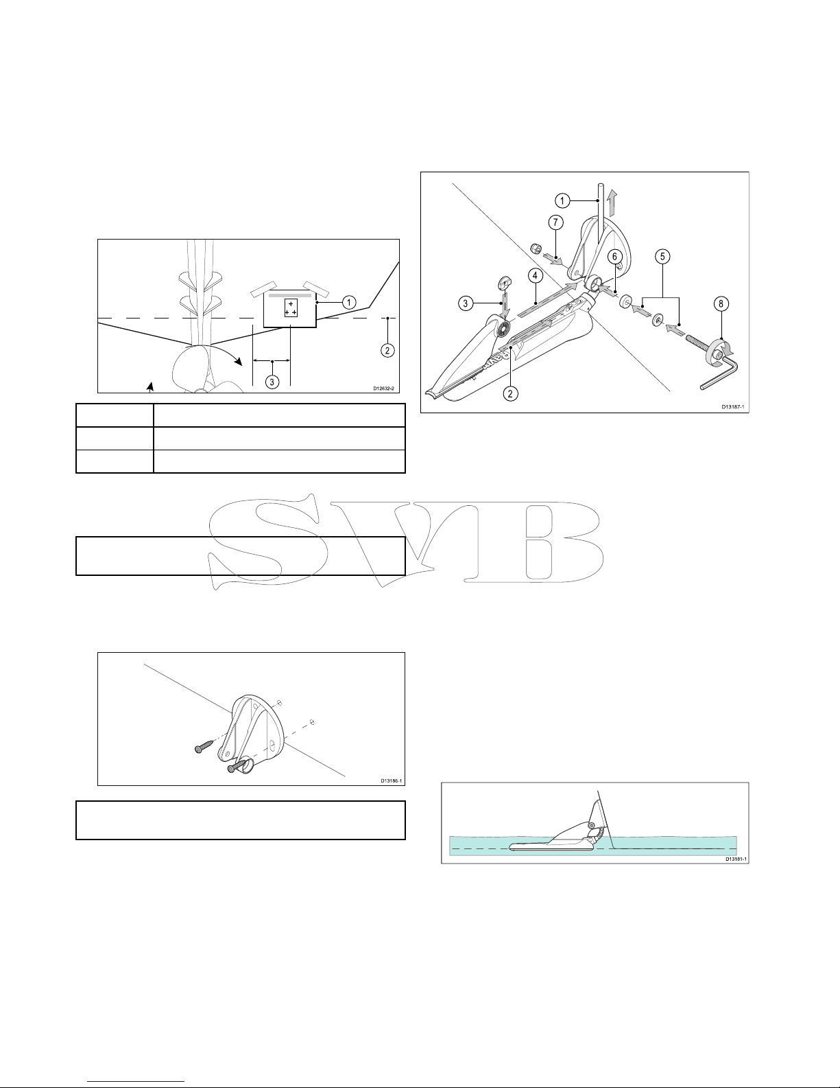
4.2Mountingthetransducer
Thetransducermustbemountedonthetransom
usingthemountingbracketprovided.Thesteps
belowdescribetheinitialmountingstepsrequired
inordertotestyourtransducersperformance.
Aftertestingthetransduceryoumustnishthe
mountingfollowingtheinstructionsintheFinishing
thetransducermountingsection.
D13187-1
2
1
3
6
8
7
4
5
1.Feedthetransducercablebetweenthepostson
themountingbracketasshown.
2.Slidetheratchetarmintotheguideonthetopof
thetransducer,ensuringitlocksinplace.
3.Holdtheratchetplateinplaceontheratchetarm
asshown.
4.Inserttheratchetarmbetweenthemounting
bracketposts,aligningthecenterholewiththe
holesintheposts.
5.SlidetheM5washerandthenthecompression
washerontotheratchetbolt.
6.Slidetheratchetboltthroughthemounting
bracketassembly.
7.InserttheM5lockingnutintothecaptivehousing
onthemountingbracket.
8.Usinga4mmHexwrench(allenkey)tighten
theratchetboltuntiltheratchetmechanismis
engagedbutcanstillbeadjustedbyhand.
9.Positionthetransducersothatthebottomfaceof
thetransducerwillbeparallelwiththewaterline
andtightentheratchetbolt.
D13181-1
Thetransducerpositionwillbeadjustedfurther
duringtesting.
30
Dragony-4/Dragony-5/WiFish
Page 31

4.3Removingthetransducer
Thetransducercanbereleasedfromthebracketby
insertingasmallmetalrodsuchasapaperclipinto
thetransducerreleaseholelocatedasshown.
D13189-1
1.Insertthemetalrodintothetransducerrelease
hole.
2.Slidethetransduceroffofthebracket.
4.4Mountingtheunit
Theunitismountedusingthebracketprovided.
Beforemountingensurethatyouhave:
•selectedasuitablelocation.
•installedthetransducerandroutedthe
power/transducercabletotheselectedlocation.
1 2
D13191-1
3 4
D13192-1
1.SlidetheHex(allen)boltthroughthepivotball,
thenslidethepivotballthroughthecenterofthe
bracketlockingcollar.
2.Usinga5mmHex(allen)key(notsupplied),
screwtheHex(allen)boltintotheundersideof
theunit,ensuringthelocatingtabsarecorrectly
aligned.
3.Usingthexingsprovidedmountthebracket
basetothemountingsurfaceasfollows:
i.Markthelocationofthebracketbase’s
mountingholesonthechosenmounting
surface.
ii.Drillholesforthexingsusingasuitabledrill,
ensuringthereisnothingbehindthesurface
thatmaybedamaged.
iii.Useapozi-drivescrewdriverandan8mm
wrench(spanner)toattachthebracketbase
securelytothemountingsurfaceusingthe
xingsprovided.
4.Positiontheunitatthedesiredangleandsecure
bytighteningthelockingcollar.
Mounting
31
Page 32

Theunitcanberemovedfromthebracket,by
unscrewingthelockingcollar.
4.5Testingandadjustingthe
transducer
Oncetheinitialmountingprocedureshavebeen
carriedout,thetransducermustbetestedpriorto
nishingthemounting.
Thetestingshouldbecarriedoutwithyourvessel
inthewater,withadepthgreaterthan0.7m(2.3
ft)butlessthanthemaximumdepthrangeofthe
transducer.
Important:TheSonarchannelwillbeableto
maintainreadingsathighervesselspeedsandat
greaterdepthsthantheDownVision
TM
application.
1.PressandholdthePowerbuttontopowerthe
uniton.
2.CompletetheStart-upwizardandtutorial.
3.Opentherelevantapplication.
Thebottomshouldbevisibleonscreenanda
depthreadingdisplayed.
4.Startmovingyourvesselatalowspeed,ensuring
youhaveadepthreadingandaclearimageis
displayed.
5.Graduallyincreasethevesselspeedwhilst
checkingthedisplay,iftheimagebecomespoor
orthebottomismissingatlowerspeedsthenthe
transducerneedstobeadjusted.
6.Angleandheightadjustmentsshouldbemadein
smallincrementsandre-testedeachtimeuntil
youobtainoptimumperformance.
D13195-1
D13196-1
7.Loosentheratchetarmbolttoadjustthe
transducerangle.
8.Loosenthe2mountingbracketscrewstoadjust
thetransducerheight.
9.Re-tightentheratchetarmboltandmounting
screwsbeforere-testing.
32
Dragony-4/Dragony-5/WiFish
Page 33

Note:
•Itmaynotalwaysbepossibletoobtaindepth
readingsathigherspeedsduetoairbubbles
passingunderthetransducer.
•Itmaybenecessarytomakeseveral
adjustmentstothetransducerbeforeobtaining
optimumperformance.
•Ifthetransducerrequiresrepositioningensure
alloldholesarelledwithmarinegradesealant.
4.6Finalizingthetransducermounting
Onceyouhaveachievedoptimumperformanceat
thedesiredvesselspeedsthetransducermustbe
lockedintopositiontocompletetheinstallation.
D13197-1
1.Drillthelockingholelocationtakingcarenotto
damagethemountingbracket.
2.Fillthelockingholewithmarinegradesealant.
3.Securethetransducerandbracketbyfully
tighteningall3mountingscrews.
4.Securetheratchetarmbolt,bytighteninguntil
thecompressionwasheriscompressedandthen
addanother1/4turn.Ifthetransducerkicksupat
speedthentightenfurther.
Note:Overtighteningmaycausedamage.
Mounting
33
Page 34

34
Dragony-4/Dragony-5/WiFish
Page 35

Chapter5:Cablesandconnections
Chaptercontents
•5.1Generalcablingguidanceonpage36
•5.2Connectionsoverviewonpage36
•5.3Connectingthecable-DV,DVS,ProandWi-Fish
TM
onpage38
•5.4Connectingthepowercable-5Monpage38
•5.5Extensioncableconnectiononpage40
Cablesandconnections35
Page 36

5.1Generalcablingguidance
Cabletypesandlength
Itisimportanttousecablesoftheappropriatetype
andlength
•Unlessotherwisestateduseonlystandardcables
ofthecorrecttype,suppliedbyRaymarine.
•Ensurethatanynon-Raymarinecablesareofthe
correctqualityandgauge.Forexample,longer
powercablerunsmayrequirelargerwiregauges
tominimizevoltagedropalongtherun.
Routingcables
Cablesmustberoutedcorrectly ,tomaximize
performanceandprolongcablelife.
•DoNOTbendcablesexcessively.Wherever
possible,ensureaminimumbenddiameterof200
mm(8in)/minimumbendradiusof100mm(4in).
100 mm (4 in)
200 mm (8 in)
•Protectallcablesfromphysicaldamageand
exposuretoheat.Usetrunkingorconduitwhere
possible.DoNOTruncablesthroughbilgesor
doorways,orclosetomovingorhotobjects.
•Securecablesinplaceusingtie-wrapsorlacing
twine.Coilanyextracableandtieitoutoftheway.
•Whereacablepassesthroughanexposed
bulkheadordeckhead,useasuitablewatertight
feed-through.
•DoNOTruncablesneartoenginesoruorescent
lights.
Alwaysroutedatacablesasfarawayaspossible
from:
•otherequipmentandcables,
•highcurrentcarryingacanddcpowerlines,
•antennae.
Strainrelief
Ensureadequatestrainreliefisprovided.Protect
connectorsfromstrainandensuretheywillnotpull
outunderextremeseaconditions.
Cableshielding
Ensurethatthecableisproperlyshieldedthatthe
cableshieldingisintact(e.g.hasn’tbeenscrapedoff
bybeingsqueezedthroughatightarea).
5.2Connectionsoverview
Dragony-4/Dragony-5,Wi-Fish
TM
productsand
theCPT-DVandCPT-DVSincludeconnectorswitha
3keywayguide.Dependingondateofmanufacture
Dragony-6,Dragony-7productsandCPT-60/
CPT-70/CPT-80transducersareavailablewith1
keywayguide(Legacy)or3keywayguide(Updated).
Adaptorcablescanbeusedtoconnect1keyway
connectorsto3keywayconnectors.
Rearconnector/Lockingcollar
ConnectorDescription
Unit/
Display
Compatible
transducer
Red–1
keyway
•Legacy
Dragony-6
•Legacy
Dragony-7
•Legacy
CPT-60
•Legacy
CPT-70
•Legacy
CPT-80
Green–3
keyway
•DVS
•Pro
•Updated
Dragony-6
•Updated
Dragony-7
•CPT-DVS
•Updated
CPT-60
•Updated
CPT-70
•Updated
CPT-80
Yellow–3
keyway
•DV
•Wi-Fish
TM
•CPT-DV
Black–3
keyway
•5M
•N/A–5
Mpower
connector
36
Dragony-4/Dragony-5/WiFish
Page 37

Transducercableconnectors
Cable
ConnectorDescriptionTransducer
Compatible
unit/display
Black–1
keyway
•Legacy
CPT-60
•Legacy
CPT-70
•Legacy
CPT-80
•Legacy
Dragony-6
•Legacy
Dragony-7
Green–3
keyway
•CPT-DVS
•Updated
CPT-60
•Updated
CPT-70
•Updated
CPT-80
•DVS
•Pro
•Updated
Dragony-6
•Updated
Dragony-7
Yellow–3
keyway
•CPT-DV
•DV
•Wi-Fish
TM
Black–3
keyway
•N/A–5
Mpower
connector
•5M
Adaptorcables
Adaptorcablesareavailabletoenableconnectionof
theolder1keywayconnectorstothenew3keyway
connectors.
Adaptorcable
Compatible
transducer
Compatible
display/unit
A80331—
CPT-DV/
CPT-DVS(3
keyway)toLegacy
Dragony-6/
Dragony-7(1
keyway)adaptor
cable
•CPT-DVS
•CPT-DV
•Updated
CPT-60
•Updated
CPT-70
•Updated
CPT-80
•Legacy
Dragony-6
•Legacy
Dragony-7
A80332—
Legacy(1
keyway)CPT-60/
CPT-70/CPT-80
transducer
toDragony-4
/Dragony-5
andWi-Fish
TM
(3
keyway)adaptor
cable
•LegacyCPT-60
•LegacyCPT-70
•LegacyCPT-80
•DV
•DVS
•Pro
•Wi-Fish
TM
•Updated
Dragony-6
•Updated
Dragony-7
Legacyandupdatedproducts
CurrentDragony-6,Dragony-7displaysand
CPT-60/CPT-70/CPT-80transducerdesignshave
beenmodiedtoincludetheimproved3keyway
connectors.
Thetablebelowidentiestheeffectivemanufacturing
datefortheimprovedkeywayconnectors.
Product
3keyway
introductiondate
3keyway
introduction
serialnumber
Dragony-6
display
January2015E700850150001
Dragony-7
display
November2014E702311140712
CPT-60
December2014A801951240023
CPT-70
February2015
TBC
CPT-80
February2015
TBC
Cablesandconnections37
Page 38

5.3Connectingthecable-DV,DVS,
ProandWi-Fish
TM
Theunithasacombinedpowerandtransducer
cablethatisattachedtothetransducer.
D13190-1
2
4
5
3
1
12 V dc
1.Connectthetransducer/powerconnectorto
therearoftheunitandsecureusingthelocking
collar.
2.Thedrainwireshouldbeconnectedtothevessel
RFgroundpoint.Ifyourvesselhasnoground
pointconnecttothenegativesideofthevessel’s
powersupply .
3.TheNegativewiremustbeconnectedtothe
negativesideofthe12Vdcpowersupply.
4.Afuseholder(notsupplied)MUSTbettedtothe
positivewireusinga5Ainlinefuse.
5.Thepositivewiremustbeconnectedtothe
positivesideofthe12Vdcpowersupply.
5.4Connectingthepowercable-5M
D13193-1
2
4
5
3
1
12 V dc
1.Connectthepowercabletotherearofthedisplay
andsecureusingthelockingcollar.
2.Thedrainwireshouldbeconnectedtothevessel
RFgroundpoint.Ifyourvesselhasnoground
pointconnecttothenegativesideofthevessel’s
powersupply .
3.TheNegativewiremustbeconnectedtothe
negativesideofthe12Vdcpowersupply.
4.Afuseholderand5Ainlinefuse(notsupplied)
MUSTbettedtothepositivewire.
5.Thepositivewiremustbeconnectedtothe
positivesideofthe12Vdcpowersupply.
Connectingthecabletothedisplay
00
0
00
0
D12779-2
2
1
1.Unlocked
2.Locked
1.Ensurethelockingcollarisintheunlocked
position.
2.Ensurethatthecableconnectorisorientated
sothatthenotchlinesupwiththeguideinthe
connector.
3.Pushthecableconnectorallthewayintothe
displayconnector.
4.Rotatethelockingcollarclockwiseuntilinthe
lockedposition(2clicks).
Warning:12Voltdconly
Thisproductmustonlybeconnectedtoa
12voltdcpowersource.
38
Dragony-4/Dragony-5/WiFish
Page 39

Warning:Powersupplyvoltage
Connectingthisproducttoavoltage
supplygreaterthanthespecied
maximumratingmaycausepermanent
damagetotheunit.RefertotheTechnical
specicationsectionforvoltagerating.
Warning:Productgrounding
Beforeapplyingpowertothisproduct,
ensureithasbeencorrectlygrounded,in
accordancewiththeinstructionsprovided.
Grounding—Dedicateddrainwire
Thepowercablesuppliedwiththisproductincludes
adedicatedshield(drain)wireforconnectiontoa
vessel'sRFgroundpoint.
ItisimportantthataneffectiveRFgroundis
connectedtothesystem.Asinglegroundpoint
shouldbeusedforallequipment.Theunitcanbe
groundedbyconnectingtheshield(drain)wireof
thepowercabletothevessel'sRFgroundpoint.
OnvesselswithoutanRFgroundsystemtheshield
(drain)wireshouldbeconnecteddirectlytothe
negativebatteryterminal.
Thedcpowersystemshouldbeeither:
•Negativegrounded,withthenegativebattery
terminalconnectedtothevessel'sground.
•Floating,withneitherbatteryterminalconnected
tothevessel'sground
Warning:Positivegroundsystems
Donotconnectthisunittoasystemwhich
haspositivegrounding.
Breakers,fusesandcircuitprotection
Theinformationbelowisprovidedasguidance
tohelpprotectyourproduct.Theexample
illustrationsprovidedareforcommonvesselpower
arrangements,ifyouareunsurehowtoprovidethe
correctlevelofprotectionthenpleaseconsulta
Raymarineauthorizeddealerforsupport.
Distributionpanelconnection
Itisrecommendedthatyourproductiswiredthrough
yourvessel’sdistributionpanelviaathermalbreaker
orfuse.
D13017-1
2 31
4 5
6 7
1.Vesselpowersupplypositive(+)
2.In-linefuse.(Ifyourproductspowercabledoes
nothaveanin-linefusethenanonefuseshould
betted.)
3.Productpowercable
4.Vesselpowersupplynegative(-)
5.*Drainwire
6.Vesseldistributionpanel
7.VesselRFgroundpointconnection
BatteryconnectionwithRFground
Ifyourvesseldoesnothaveadistributionpanelthen
yourproductmaybewireddirectlytothebatterywith
thedrainwireconnectedtothevessel’sRFground
point.
D13018-1
2 4 51 3
6 7
1.Vesselpowersupplypositive(+)
2.Vesselpowersupplynegative(-)
3.In-linefuse(Ifyourproductspowercabledoes
nothaveabuiltinfusethenanin-linefuse
shouldbetted.)
4.*Drainwire
5.Productpowercable
6.Vesselbattery
7.VesselRFgroundpointconnection
BatteryconnectionwithnoRFground
Ifyourvesseldoesnothaveadistributionpanel
oranRFgroundpointthenyourproductmaybe
wireddirectlytothebatterywiththedrainwirealso
connectedtothebattery’snegativeterminal.
D13019-1
2 4 51 3
6
1.Vesselpowersupplypositive(+)
2.Vesselpowersupplynegative(-)
3.In-linefuse(Ifyourproductspowercabledoes
nothaveabuiltinfusethenanin-linefuse
shouldbetted.)
4.Drainwireconnectedtovesselnegativepower
supply.
5.Productpowercable
6.Vesselbattery
In-linefuseandthermalbreakerratings
Thefollowingin-linefuseandthermalbreakerratings
applytoyourproduct:
In-linefuseratingThermalbreakerrating
2Aslowblow
3A(ifonlyconnectingone
device)
Cablesandconnections39
Page 40

Note:
•Thesuitablefuseratingforthethermalbreaker
isdependentonthenumberofdevicesyouare
connecting.Ifindoubtconsultanauthorized
Raymarinedealer.
•Y ourproduct’spowercablemayhavetted
in-linefuse,ifnotthenyoucanaddanin-line
fusetothepositivewireofyourproductspower
connection.
5.5Extensioncableconnection
Anoptionalextensioncablecanbeusedtoextend
thedistancefromthetransducertotheunitbyup
to4m(13.1ft).
12 V dc
D13241-1
2
1
3
1.Existingcable.
2.Extensioncable(connectedtothevessel’s
powersupplyandtotheexistingcable.
3.Isolatedpowersupplywiresonexisting
transducercable.
Note:
•Only1extensioncableshouldbeusedper
installation.
•Thelengthofthepowersupplywiresonthe
extensioncableis2m(6.6ft).
Maximumtransducercablelength
Themaximumcablelengthfromthetransducerto
theunitisshownbelow.
CPT-DV8m(26.2ft.)—4m(13.1ft.)
suppliedcable+4m(13.1ft.)
extensioncable
CPT-DVS10m(32.8ft.)—6m(19.7
ft.)suppliedcable+4m(13.1
ft.)extensioncable
Note:Extendingthetransducercablefurtherthan
themaximumstateddistancewillcausepoor
performance.
40
Dragony-4/Dragony-5/WiFish
Page 41

Chapter6:Wi-Fish
TM
Chaptercontents
•6.1Wi-Fishcontrolsonpage42
•6.2Switchingtheunitonandoffonpage42
•6.3Wi-Fish
TM
mobileapponpage43
•6.4Wi-Fish
TM
initialsetuponpage44
•6.5DepthOffsetonpage44
•6.6Switchingonthesimulator—Wi-Fish
TM
apponpage45
•6.7OpeningtheMicroSDcardreadercoveronpage45
Wi-Fish
TM
41
Page 42

6.1Wi-Fishcontrols
D13199-1
2 3 4
1
1.Powerindicator(quickGreenash=initializing,
slowGreenash=normaloperation,Red=
devicefailed)
2.Wi-Ficonnectionindicator(quickBlueash=
notconnected,slowBlueash=connected)
3.Powerbutton
4.MicroSDcardreader
6.2Switchingtheunitonandoff
Poweringtheuniton
1.PressandholdthePowerbuttonfor
approximately3secondstopoweruptheunit.
*Ondisplayproductsafterapproximately5
secondsthesplashscreenisdisplayed.
2.*PressOKtoaccepttheLimitationsofUse
disclaimerwhenitappears.
Note:*DoesnotapplytoWi-Fish
TM
.
Poweringtheunitoff
1.PressandholdthePowerbuttonfor
approximately6seconds.
Ondisplayproductsa3secondcount-downtimer
willbedisplayed.
Note:T ocancelthepoweroffprocess,releasethe
powerbuttonbeforetheunitpowersoff.
42
Dragony-4/Dragony-5/WiFish
Page 43

6.3Wi-Fish
TM
mobileapp
Raymarine’sWi-Fish
TM
mobileappisavailableon
iOS7orgreaterandAndroid4orgreaterwhichmust
beusedtocontroltheWi-Fish
TM
Wi-Fisonarmodule
usingasmartdevicesuchasatabletorsmartphone.
D13242-1
TheWi-Fish
TM
appcanbedownloadedfromthe
relevantappstores.
ConnectingWi-Fi—Wi-Fish
TM
D13198-1
Model No E70290
Product: Wi-Fish
Serial No. 1040009
SSID: 1234567890
Passphrase: ************
EXAMPLE
1.InstalltheWi-Fish
TM
appfromtherelevantapp
store.
2.Connectyoursmartdevice’sWi-Fitothe
Wi-Fish
TM
unit.
Theproduct’suniquebroadcastingIDknownas
theSSID(ServiceSetIdentier)andPassphrase
foryourproductcanbefoundontheproductlabel
xedtothebottomoftheunit.Itisrecommended
thatyoutakenoteoftheseandretainsomewhere
safeforfuturereference.
3.OpentheWi-Fish
TM
app.
Connectingyoursmartdevice
Yoursmartdevice’sWi-Ficonnectionmustbe
connectedtotheproducttoenableuseofthemobile
Wi-Fish
TM
app.
WiththeWi-Fish
TM
mobileappinstalledonyour
smartdevice:
D13243-1
3 4
1 2
1.OpentheWi-Fisettingsonyoursmartdevice
andselectyourproduct’sSSIDfromthelistof
availabledevices.
Yourproduct’sSSIDcanbefoundontheproduct
labellocatedonthebottomoftheunit.
2.Enteryourproductpassphrase.
Yourproduct’spassphrasecanalsobefoundon
theproductlabellocatedonthebottomofthe
unit.
3.Yourdevicewillnowconnecttotheunitand
obtainanIPaddress.
4.Onceyourdeviceisconnectedyoucanopenthe
Wi-Fish
TM
app.
Wi-Fish
TM
43
Page 44

6.4Wi-Fish
TM
initialsetup
OncetheWi-Fish
TM
unitisinstalledandconnected
toyoursmartdevice,whichisrunningthelatest
versionoftheWi-Fish
TM
app,itisrecommended
thatthefollowingtasksarecompleted:
•Congureunitsofmeasurefordepthand
temperaturereadings
•Setatransduceroffset
•Viewtheapp’sHelppages
•Familiarizeyourselfwiththeproductusing
SimulatorMode.
TheseoptionsareavailableintheWi-Fish
TM
mobile
app’sMoremenuwhichincludesthefollowing
settings:
•Settings
–Transducerdepthoffset
–Depthunits
–Temperatureunits
–Simulator
•Help
•About
.
6.5DepthOffset
Depthsaremeasuredfromthetransducertothesea
bed,butyoucanapplyanoffsetvaluetothedepth
data,sothatthedisplayeddepthreadingrepresents
thedepthtotheseabedfromeitherthekeelorthe
waterline.
Beforeattemptingtosetawaterlineorkeel
offset,ndouttheverticalseparationbetweenthe
transducerandeitherthewaterlineorthebottomof
thekeelonyourvessel,asappropriate.Thensetthe
appropriatedepthoffsetvalue.
D9343--2
1 2 3
1
Waterlineoffset
2
Transducer/Zerooffset
3
Keeloffset
Ifanoffsetisnotapplied,displayeddepthreadings
representthedistancefromthetransducertothe
seabed.
Assigningatransducerdepthoffset—
Wi-Fish
TM
app
Followthestepsbelowtoassignadepthoffsetvalue
toyourdepthreadings.
WiththeWi-Fish
TM
mobileappconnectedand
runningonyoursmartdevice:
1.SelecttheMoreicon(threeverticaldots).
2.SelectSettings.
3.SelectTransducerDepthOffset.
4.Adjustthedepthoffsettotherequiredvalue.
44
Dragony-4/Dragony-5/WiFish
Page 45

6.6Switchingonthesimulator—
Wi-Fish
TM
app
Thesimulatormaybeusedtofamiliarizeyourself
withthefeaturesandfunctionsoftheproduct.
WiththeWi-Fish
TM
mobileappconnectedtoyour
Wi-Fish
TM
unitandrunning:
1.Select.
2.SelectSettings.
3.SelectSimulator.
4.SelectOntoswitchsimulatormodeon,or
5.SelectOfftoswitchthesimulatormodeoff.
Insimulatormodetheappwillhavethesame
functionality,howeversimulatedsonardatais
displayedinsteadoflivesonardata.
6.7OpeningtheMicroSDcardreader
cover
TheMicroSDcardreaderislocatedontherearofthe
unit.Thecardreaderisprotectedbyaweatherproof
cover.
D13244-1
1 2
3
1.Coverclosed
2.Openingcover
3.Coveropen
1.Openthecardreadercoverbypullingbackwards
onthecover’shandleuntilthecoverispositioned
asshownin(3)above.
Thecoverhasatighttandmayrequiresome
forcetoopenthecover.
2.Whenclosingthecoverensurethatitisfully
closedallthewayaroundtheedge,thiswill
providetheweatherproofseal.
InsertingaMicroSDcard
1 2
D13245-1
Withthecardreader’scoveropen:
1.Insertthecardwiththecontactsfacingdown.
Wi-Fish
TM
45
Page 46

2.GentlypresstheMicroSDcardallthewayinto
thecardreaderslot.
3.T opreventwateringressanddamagetotheunit,
ensurethecardreader’scoverisfullyclosed.
RemovingaMicroSDcard
1 2
D13246-1
1.OndisplayproductsselectEjectSDCardfrom
theShortcutspage.
2.Openthecardreader’scover.
3.PinchtheprotrudingedgeoftheMicroSDcard
betweenyourindexngerandthumbandpullthe
cardclearofthecardreaderslot.
4.T opreventwateringressanddamagetotheunit,
ensurethecardreader’scoverisfullyclosed.
46
Dragony-4/Dragony-5/WiFish
Page 47

Chapter7:Gettingstarted
Chaptercontents
•7.1Controls—DV,DVS,ProandMonpage48
•7.2Switchingtheunitonandoffonpage48
•7.3Initialsetupproceduresonpage49
•7.4Satellite-basednavigationonpage50
•7.5Checkingthesonarapplicationonpage51
•7.6CheckingtheDownVision
TM
applicationonpage52
•7.7Shortcutspageonpage52
•7.8Applicationsonpage53
•7.9Viewswitcheronpage54
•7.10Memorycardsandchartcardsonpage55
•7.11Learningresourcesonpage56
Gettingstarted
47
Page 48

7.1Controls—DV,DVS,ProandM
1 2 3 4 5 6
D13194-1
1
–buttonZoomout/Rangeout
2
+buttonZoomin/Rangein
3
DirectionaltrackpadwithOKbutton—Usedfor
navigatingmenusandapplicationsandselecting
items.
4
Backbutton/Viewswitcherbutton
•Pressoncetoreturntoapreviousmenuor
applicationstate.
•PressintheChartapplicationtoexitcursormode
andcentrethevesselon-screen.
•PressintheSonarorDownVisionapplicationsto
resumescrollingfromapausedstate.
•Fromthetoplevelapplicationstate(Motionmode
orScrollingmode)pressoncetoopentheView
switcher(DVSandProvariantsonly).
5
Power/Shortcutspagebutton
•Pressoncetopowertheuniton.
•Whenturnedon,pressingthepowerbuttonwill
displaytheShortcutspage.
•Pressandholdtoturnthedisplayoff.
6
MicroSDcardreader–openthechartreadercover
toinsertorremoveaMicroSDcard.Thecardreader
canbeusedforsoftwareupdates,electroniccharts
andarchivingdataandusersettings.
Note:Electroniccartographycanonlybeused
withtheProandMvariants.
7.2Switchingtheunitonandoff
Poweringtheuniton
1.PressandholdthePowerbuttonfor
approximately3secondstopoweruptheunit.
*Ondisplayproductsafterapproximately5
secondsthesplashscreenisdisplayed.
2.*PressOKtoaccepttheLimitationsofUse
disclaimerwhenitappears.
Note:*DoesnotapplytoWi-Fish
TM
.
Poweringtheunitoff
1.PressandholdthePowerbuttonfor
approximately6seconds.
Ondisplayproductsa3secondcount-downtimer
willbedisplayed.
Note:T ocancelthepoweroffprocess,releasethe
powerbuttonbeforetheunitpowersoff.
48
Dragony-4/Dragony-5/WiFish
Page 49

7.3Initialsetupprocedures
Onceyourdisplayhasbeeninstalledand
commissioned,itisrecommendedthatyougo
throughtheinitialstartupwizardandtutorial.
Startupwizard
Whenyoupower-upthedisplayforthersttimeor
afterasystemreset,theStartupWizardisdisplayed
afteryouhaveacceptedtheLimitationsOnUse
disclaimer.TheStartupWizardguidesyouthrough
thefollowinginitialsettings:
1.Languageselection.
2.Congureunits.
3.Finish/Tutorial.
Note:Thesesettingscanalsobesetatanytime
usingtheSystemSettingsmenuaccessiblefrom
theTools&Settingspage.
Additionaltasks
InadditiontothesettingscoveredbytheWizard,it
isalsorecommendedthatthefollowingtasksare
completed:
•Setyourdateandtimepreferences(ifapplicable).
•Setyourtransducerdepthoffset(ifapplicable).
•Familiarizeyourselfwiththeproductusing
SimulatorMode.
Accessingthesystemsettingsmenu
Dependingondisplayvariant,theSystemSettings
menucanbeaccessedby:
•selectingSystemSettingsfromtheTools&
Settingspage(DVSandPro),orby
•selecting:Menu>SystemSettingsfromthe
applicationmenu(DVand5M).
Settingtimeanddatepreferences
UnitsthatincludeaninternalGNSS
(GPS/GLONASS)receivercantimestamp
waypointsandtrackswiththedateandtimeinyour
preferredformat.Fishnderonlyproductsdonot
includedateandtimesettings.
FromtheSystemSettingsmenu:
1.SelectTimeandDateSet-up.
2.UsetheDateFormat,TimeFormat,andLocal
Time:menuitemstosetyourtimeanddate
preferences.
DepthOffset
Depthsaremeasuredfromthetransducertothesea
bed,butyoucanapplyanoffsetvaluetothedepth
data,sothatthedisplayeddepthreadingrepresents
thedepthtotheseabedfromeitherthekeelorthe
waterline.
Beforeattemptingtosetawaterlineorkeel
offset,ndouttheverticalseparationbetweenthe
transducerandeitherthewaterlineorthebottomof
thekeelonyourvessel,asappropriate.Thensetthe
appropriatedepthoffsetvalue.
D9343--2
1 2 3
1
Waterlineoffset
2
Transducer/Zerooffset
3
Keeloffset
Ifanoffsetisnotapplied,displayeddepthreadings
representthedistancefromthetransducertothe
seabed.
Settingthedepthoffset
OnFishnderproductsyoumustapplyanoffset
valuefordepthreadings.
FromtheSystemSettingsmenu:
1.SelectSonarSet-up.
2.SelectDepthOffset.
Thedepthoffsetnumericadjustcontrolis
displayed.
3.Adjusttheoffsettotherequiredvalue.
4.SelectOktoconrmthenewvalueandclosethe
numericadjustcontrol.
Simulatormode
TheSimulatormodeenablesyoutopractice
operatingyourdisplaywithoutdatafromtheGPS
receiverortransducer.
Thesimulatormodeisswitchedon/offinthe
SystemSettingsmenu.
Note:RaymarinerecommendsthatyoudoNOT
usethesimulatormodewhilstnavigating.
Note:ThesimulatorwillNOTdisplayanyreal
data.Thisincludessafetymessages.
Enablinganddisablingsimulatormode
Youcanenableanddisablesimulatormodeby
followingthestepsbelow.
FromtheSystemSettingsmenu:
1.SelectSimulator:.
2.SelectOntoturnsimulatormodeon,or
3.SelectOfftoturnsimulatormodeoff.
Note:TheDemomovieoptionisforretail
demonstrationpurposesonly.
Gettingstarted
49
Page 50

7.4Satellite-basednavigation
GPSStatus
ProductswithaninternalGPSreceiverorGNSS
(GPS/GLONASS)receivercanusetheGPSstatus
pagetoviewthestatusoftheavailablesatellitesthat
arecompatiblewithyourreceiver.
Thesatelliteconstellationsareusedtopositionyour
boatintheChartapplication.Y oucansetupyour
receiverandcheckitsstatusfromtheGPSSet-up
menu.Foreachsatellite,thescreenprovidesthe
followinginformation:
1
2
3
D13122-1
1.Skyview
2.Satellitestatus
3.Positionandxinformation
Skyview
Skyviewisavisualrepresentationthatshows
thepositionofnavigationsatellitesandtheirtype.
Satellitetypesare:
•Circle—Acircleidentiesasatellitefromthe
GPSconstellation.
•Square—Asquareidentiesan(SBAS)
differentialsatellite.
•Diamond—Adiamondidentiesasatellitefrom
theGLONASSconstellation.
Satellitestatusarea
TheSatellitestatusareadisplaysthefollowing
informationabouteachsatellite:
•Type—Identieswhichconstellationthesatellite
belongsto.
•ID—Displaysthesatellitesidenticationnumber.
•CNO(Carrier-to-noiseratio)—Displaysthesignal
strengthofeachsatelliteshownintheSkyview:
–Grey=searchingforsatellite
–Green=satelliteinuse
–Orange=trackingsatellite
•AzimuthandElevation—Providestheangleof
elevationandazimuthbetweenthelocationofthe
receiverandthesatellite.
Positionandxinformation
Thefollowingpositionalandxinformationis
provided:
•HorizontalDilutionofPrecision(HDOP)
—HDOPisameasureofsatellitenavigation
accuracy,calculatedfromanumberoffactors
includingsatellitegeometry,systemerrorsin
thedatatransmissionandsystemerrorsinthe
receiver.Ahigherguresigniesagreater
positionalerror.Atypicalreceiverhasanaccuracy
ofbetween5and15m.Asanexample,assuming
areceivererrorof5m,anHDOPof2would
representanerrorofapproximately15m.Please
rememberthatevenaverylowHDOPgureis
NOguaranteethatyourreceiverisprovidingan
accurateposition.Ifindoubt,checkthedisplayed
vesselpositionintheChartapplicationagainst
youractualproximitytoaknownchartedobject.
•EstimatedHorizontalPositionError(EHPE)
—EHPEisameasureoftheestimatederrorof
apositionxinthehorizontalplane.Thevalue
displayedindicatesthatyourpositioniswithina
circleradiusofthestatedsize50%ofthetime.
•Fixstatus—indicatestheactualmodethe
receiverisreporting:
–Fix—Satellitexhasbeenacquired.
–NoFix—Nosatellitexcanbeacquired.
–DFix—Adifferentialbeaconxhasbeen
acquired.
–SDFix—Adifferentialsatellitexhasbeen
acquired.
•Position—Displaysthelatitudeandlongitude
positionofyourreceiver.
•Date/Time—Displaysthecurrentdateandtime
generatedbythepositionxinUTCformat.
•Mode—Identieswetherthereceiverisworking
indifferentialmodeornon-differentialmode.
•Datum—Thereceiver'sdatumsettingaffects
theaccuracyofthevesselpositioninformation
displayedintheChartapplication.Inorderforyour
receiverandMFDtocorrelateaccuratelywithyour
papercharts,theymustbeusingthesamedatum.
CheckingGPSoperation
YoucancheckthattheGPSisfunctioningcorrectly
usingtheChartapplication.
1.OpentheChartapplication.
2.Checkthescreen.
Youshouldsee:
Yourvesselposition(indicatesaGPSx).
Yourcurrentpositionisrepresentedbyavessel
symbolorsolidcircle.
Asolidcircleonthechartindicatesthatthe
vesselspeedistoolow(i.e.lessthan0.15kts)to
provideCourseOverGround(COG)data.
50
Dragony-4/Dragony-5/WiFish
Page 51

Note:Itisrecommendedthatyoucheckthe
displayedvesselpositionintheChartapplication
againstyouractualproximitytoaknowncharted
object.GNSSreceiverstypicallyhaveanaccuracy
ofbetween5mand15m.
Note:AGPSStatusscreenprovidessatellite
signalstrengthandotherrelevantinformation.
7.5Checkingthesonarapplication
ProductswhichincludetheSonarapplicationandthe
CPT-DVStransducercanusetheSonarapplication
tohelptargetsh.
FromtheSonarapplication:
1.Checkthedisplay .
Withthetransduceractiveyoushouldseea
scrolling(lefttoright)imagethatshowsthe
bottomandunderwaterstructure,youshouldalso
seeadepthreadinginthetopleftdatabox.
Gettingstarted
51
Page 52

7.6CheckingtheDownVision
TM
application
ProductswhichincludetheDownVision
TM
applicationandtheCPT-DVorCPT-DVStransducer
canusetheDownVision
TM
applicationtodisplay
underwaterstructureandobjects.
FromtheDownVision
TM
application:
1.Checkthedisplay .
Withthetransduceractiveyoushouldseea
scrolling(lefttoright)imagethatshowsthe
bottomstructure,youshouldalsoseeadepth
readinginthetopleftdatabox.
7.7Shortcutspage
Theshortcutspageprovidesaccesstothefollowing
functions:
D12781-2
2
4
5
3
1
1Brightnesscontrol.
2
PowerSavemode—selectingwillactivate
PowerSavemode.
3
Enable/DisableSonar—selectingwillenableor
disabletheinternalsonarandDownVision.
4
EjectSDcard—selecttosafelyremovethe
memorycard.
5
Screencapture—selectingsavesascreenshotto
memorycard.
Openingtheshortcutspage
Withthedisplaypoweredon:
1.PressthePowerbuttononce.
Theshortcutspageisdisplayed.
2.UsetheDirectionalcontrolstohighlightan
option.
3.PresstheOKbuttontoselecttheoption.
Adjustingthedisplaybrightness
1.PressthePOWERbuttononce.
TheShortcutspageisdisplayed.
2.Adjustthebrightnesstotherequiredlevelusing
theT rackpad.
Note:Thebrightnesslevelcanalsobeincreased
bypressingthePowerbuttonmultipletimes.
PowerSavemode
InPowerSavemodeallfunctionsoftheproduct
remainactive,butthedisplayisplacedintoalow
powerstate.PowerSavemodeiscancelledby
pressingaphysicalbuttonorwhenanalarmevent
occurs.
EnablingPowerSavemode
ToenablePowerSavemodefollowthestepsbelow.
1.PressthePOWERbutton.
Theshortcutsmenuisdisplayed.
2.SelectPowerSaveMode.
ThedisplayisnowinPowerSavemode.
3.YoucanwakethedisplayfromPowerSavemode
atanytimebypressingaphysicalbutton.
Note:PowerSavemodeisautomaticallycancelled
ifanalarmeventoccurs.
52
Dragony-4/Dragony-5/WiFish
Page 53

DisablingandenablingtheSonar
Thetransducerpingcanbedisabledandenabled
fromtheshortcutspage.
1.SelectDisableSonartostopthetransducer
pinging.
2.SelectEnableSonartostartthetransducer
pinging.
Note:
•Whenenabled,thesonarelementwillpingifthe
viewdisplayedcontainstheSonarapplication
ortheChartapplication
•Whenenabled,theDownVision
TM
element
willpingonlyiftheviewdisplayedincludesthe
DownVision
TM
application.
Screenshots
Youcantakeascreenshotofwhatiscurrently
displayedonthescreen.
Screenshotsaresavedin.png(PortableNetwork
Graphic)formattoaMicroSDCard.Thesaved
imagescanbeviewedfromanydevicecapableof
viewing.pngimages.
Takingascreenshot
Youcantakeascreenshotbyfollowingthesteps
below.
1.InsertaMicroSDcardwithsuitablefreespace
intothecardreader.
2.PressthePowerbutton.
TheShortcutspageisdisplayed:
3.SelecttheCameraicon.
Aconrmationmessageisdisplayed.
4.SelectOK.
ThescreenshotisnowsavedtotheMicroSD
card.
TipIfyourdisplayhasaBackbuttonyoucanalso
takeascreenshotbypressingandholdingtheBack
buttonuntiltheconrmationmessageappears.
7.8Applications
Theapplicationsavailableonyourdisplayare
dependentuponproductvariant.
Description
Applicable
Products
Chartapplication—providesa
2Dgraphicalviewofyourcharts
tohelpyounavigate.Waypoint
andtrackfunctionsenableyouto
navigatetoaspeciclocationor
recordwhereyou'vebeen.Chart
cardsprovidehigherlevelsof
detail.
•Pro
•M
Sonarapplication—this
applicationusesCHIRPprocessing
tohelpyoutargetshbeneathyour
vessel.Y oucanalsoviewwater
depth,watertemperatureandmark
pointsofinterestsuchasshing
spotsorwrecks.
•DVS
•Pro
DownVisionapplication—
thisapplicationgivesincreased
coverageeithersideofthevesselin
highdenition.CHIRPprocessing
andhigheroperatingfrequency
allowsgreaterdepthresolution,
makingiteasiertoidentifybottom
structuresaroundwhichshmay
reside.Y oucanalsoviewwater
depth,watertemperatureandmark
pointsofinterestsuchasshing
spotsorwrecks.
•DV
•DVS
•Pro
Tools&Settings—provides
accesstoalarms,systemsettings,
backupandresetfeatures.
•DVS
•Pro
Gettingstarted
53
Page 54

7.9Viewswitcher
Productsthatincludemorethan1applicationuse
theViewSwitchertocyclethroughavailableviews.
Fullscreenandsplitscreenapplicationviewsare
available.
3
4
2
1
D12634-1
1Viewthumbnails
2Activeapplication
3Viewswitcher
4Viewswitchertitlebar
Theviewsavailablearedependentonproduct
variantbutcaninclude:
•Chartapplication
•Sonarapplication
•DownVisionapplication
•DownVision/Sonarapplication—splitscreen
•Chartapplication/Sonarapplication—splitscreen
•Chartapplication/DownVisionapplication—
splitscreen
•T ools&Settings
OpeningtheViewswitcher
Fromthetoplevelapplicationstate(Motionmode
orScrollingmode):
1.PresstheBackbutton.
UsingtheViewswitcher
Toselectaviewfollowthestepsbelow.
WiththeViewswitcherdisplayed:
1.UsetheDirectionalcontrolstohighlightaview.
2.PresstheOKbuttontodisplaythechosenview.
Selectingtheactivepaneinsplitscreen
views
Whenasplitscreenviewisdisplayedyoucan
changetheactivepane(thepanethatyouwantto
control)usingtheViewswitcher.
Withasplitscreenviewdisplayed.
1.IfrequiredpresstheBackbuttontochangethe
ChartapplicationtoMotionmode,ortheSonar
andDownVisionapplicationstoScrollingmode.
2.PresstheBackbuttonagain.
TheViewswitcherisdisplayed.
3.UsetheDirectionalcontrolstohighlightthe
paneyouwanttomakeactive.
4.PresstheOKbuttontoconrm.
Theselectedviewisdisplayedandaborderis
placedaroundtheactivepane.
54
Dragony-4/Dragony-5/WiFish
Page 55

7.10Memorycardsandchartcards
MicroSDmemorycardscanbeusedtobackup/
archivedata(e.g.Waypoint,andTracks).Once
dataisbackeduptoamemorycardolddatacan
bedeletedfromthesystem,creatingcapacityfor
newdata.Thearchiveddatacanberetrievedatany
time.Chartcardsprovideadditionalorupgraded
cartography.
Itisrecommendedthatyourdataisbackeduptoa
memorycardonaregularbasis.DoNOTsavedata
toamemorycardcontainingcartography.
Compatiblecards
ThefollowingtypesofMicroSDcardsarecompatible
withyourdisplay:
•MicroSecureDigitalStandard-Capacity
(MicroSDSC)
•MicroSecureDigitalHigh-Capacity(MicroSDHC)
Note:
•Themaximumsupportedmemorycardcapacity
is32GB.
•MicroSDcardsmustbeformattedtouseeither
theFA TorFA T32lesystemformattoenable
usewithyourMFD.
Speedclassrating
Forbestperformanceitisrecommendedthatyou
useClass10orUHS(UltraHighSpeed)class
memorycards.
Chartcards
Yourproductispre-loadedwithelectroniccharts
(worldwidebasemap).Ifyouwishtousedifferent
chartdata,youcaninsertcompatiblechartcardsinto
theunit'smemorycardreader.
Usebrandedchartcardsandmemorycards
Whenarchivingdataorcreatinganelectronicchart
card,Raymarinerecommendstheuseofquality
brandedmemorycards.Somebrandsofmemory
cardmaynotworkinyourunit.Pleasecontact
customersupportforalistofrecommendedcards.
Caution:Careofchartandmemory
cards
Toavoidirreparabledamagetoand/or
lossofdatafromchartandmemorycards:
•DONOTsavedataorlestoacard
containingcartographyasthecharts
maybeoverwritten.
•Ensurethatchartandmemorycards
arettedthecorrectwayaround.DO
NOTtrytoforceacardintoposition.
•DONOTuseametallicinstrumentsuch
asascrewdriverorplierstoinsertor
removeachartormemorycard.
OpeningtheMicroSDcardreadercover
TheMicroSDcardreaderislocatedontherearofthe
unit.Thecardreaderisprotectedbyaweatherproof
cover.
D13244-1
1 2
3
1.Coverclosed
2.Openingcover
3.Coveropen
1.Openthecardreadercoverbypullingbackwards
onthecover’shandleuntilthecoverispositioned
asshownin(3)above.
Thecoverhasatighttandmayrequiresome
forcetoopenthecover.
2.Whenclosingthecoverensurethatitisfully
closedallthewayaroundtheedge,thiswill
providetheweatherproofseal.
InsertingaMicroSDcard
1 2
D13245-1
Withthecardreader’scoveropen:
1.Insertthecardwiththecontactsfacingdown.
2.GentlypresstheMicroSDcardallthewayinto
thecardreaderslot.
Gettingstarted
55
Page 56

3.T opreventwateringressanddamagetotheunit,
ensurethecardreader’scoverisfullyclosed.
RemovingaMicroSDcard
1 2
D13246-1
1.OndisplayproductsselectEjectSDCardfrom
theShortcutspage.
2.Openthecardreader’scover.
3.PinchtheprotrudingedgeoftheMicroSDcard
betweenyourindexngerandthumbandpullthe
cardclearofthecardreaderslot.
4.T opreventwateringressanddamagetotheunit,
ensurethecardreader’scoverisfullyclosed.
7.11Learningresources
Raymarinehasproducedarangeoflearning
resourcestohelpyougetthemostoutofyour
products.
Videotutorials
Raymarineofcialchannelon
YouTube:
•http://www.youtube.com/u-
ser/RaymarineInc
VideoGallery:
•http://www.rayma-
rine.co.uk/view/?id=2679
ProductSupportvideos:
•http://www.rayma-
rine.co.uk/view/?id=4952
Note:
•Viewingthevideosrequiresadevicewithan
Internetconnection.
•SomevideosareonlyavailableinEnglish.
Trainingcourses
Raymarineregularlyrunsarangeofin-depthtraining
coursestohelpyoumakethemostofyourproducts.
VisittheTrainingsectionoftheRaymarinewebsite
formoreinformation:
•http://www.raymarine.co.uk/view/?id=2372
FAQsandKnowledgeBase
RaymarinehasproducedanextensivesetofFAQs
andaKnowledgeBasetohelpyoundmore
informationandtroubleshootanyissues.
•http://www.raymarine.co.uk/knowledgebase/
Technicalsupportforum
YoucanusetheT echnicalsupportforumtoask
atechnicalquestionaboutaRaymarineproduct
ortondouthowothercustomersareusing
theirRaymarineequipment.Theresourceis
regularlyupdatedwithcontributionsfromRaymarine
customersandstaff:
•http://raymarine.ning.com/
56
Dragony-4/Dragony-5/WiFish
Page 57

Chapter8:Fishnderapplications
Chaptercontents
•8.1DownVision
™
applicationoverviewonpage58
•8.2Sonarapplicationoverviewonpage58
•8.3Fishnderapplications'featuresonpage60
•8.4Fishnderapplications’controlsonpage60
•8.5Zoomonpage61
•8.6Rangeonpage62
•8.7Scrollingonpage62
•8.8A-Scopemodeonpage63
•8.9DisplayOptionsonpage63
•8.10Colorsonpage64
•8.11Sensitivityadjustmentsonpage65
•8.12DVSystemsettingsmenuoptionsonpage66
Fishnderapplications
57
Page 58

8.1DownVision
™
applicationoverview
TheDownVision
™
applicationusesacompatible
transducertoproduceadetailedstructureviewof
thewatercolumnbeneathyourvesselThisenables
youtoaccuratelydistinguishbottomstructure,and
underwaterobjects.DownVision
™
usesCHIRP
processingwithacentered350KHzpingfrequency,
whichprovidesahigherresolutionimagethanthe
Sonarapplication.
TheDownVision
™
applicationdisplaysascrolling
imagewhichscrollsfromrighttoleftacrossthe
screen.
TheDownVision
™
applicationusesmonochrome
palettesandshadingtodifferentiatebetweentarget
strengths.
D12780-1
7
1
3
6
2
4
5
1
Depthreading—Currentdepthofthebottom.
2
Scrollingpaused—Scrollingpauseswhenthe
Joystickisusedtomovethecursoraroundthescreen).
3Depthlines—Horizontaldashedlinesdrawnatregular
intervalstoindicatethedepthfromthesurface.
4
Cursor—Displayedincursormode.
5
Depthmarkers—Thesenumbersindicatedepth.
6
Speed—CurrentvesselSpeedOverGround(SOG).
OnlyapplicabletodisplayswithGPS/GNSSreceivers
7
Watertemperature—Currentwatertemperature.
8.2Sonarapplicationoverview
TheSonarapplicationusesacompatibletransducer
toproduceadetailedviewofshandthewater
columnincludingbottomunderyourvessel.This
enablesyoutoaccuratelydistinguishbetween
differentsizesofsh,bottomstructure,and
underwaterobjects.TheSonarapplicationuses
CHIRPprocessingwithacentered200KHzping
frequency,whichprovidesagreaterdepthrange
thanDownVision™butlessdetail.
TheSonarapplicationdisplaysascrollingimage
whichscrollsfromrighttoleftacrossthescreen.
TheSonarapplicationusesdifferentcolorsto
differentiatetargetstrengths.Thecolorsusedare
dependentupontheselectedcolorpalette(e.g.the
classicbluecolorpaletteusesbluetoidentifythe
weakesttargetsandredforthestrongest).
D12782-1
8 9
1
3
5
7
2
4
6
1
Depthreading—Currentbottomdepth.
2
Scrollingpaused—Scrollingpauseswhenthe
Joystickisusedtomovethecursoraroundthescreen).
3Depthlines—Horizontaldashedlinesdrawnatregular
intervalstoindicatethedepthfromthesurface.
4
Cursor—Displayedincursormode.
5
Bottomline—Displaysathicklinetoidentifythe
bottom.
6Depthmarkers—Thesenumbersindicatedepth.
7
Speed—CurrentvesselSpeedOverGround(SOG).
OnlyapplicabletodisplayswithGPS/GNSSreceivers
8
Watertemperature—Currentwatertemperature.
9DepthTargetID—Depthsaredisplayedagainst
recognizedtargets.ThesensitivityoftheseIDsis
directlylinkedtotheFishAlarmsensitivity;thegreater
theshalarmsensitivity,thegreaterthenumberof
labelledreturns.
Thesonarimage
Interpretingthebottomusingsonar
Itisimportanttounderstandhowtocorrectlyinterpret
thebottomstructurerepresentedon-screen.
Thebottomusuallyproducesastrongecho.
Thefollowingimagesshowhowdifferentbottom
conditionsarerepresentedon-screen:
58
Dragony-4/Dragony-5/WiFish
Page 59

D6855-3
1
2
3
ItemDescription
1
Ahardbottom(sand)producesathinline.
2
Asoftbottom(mudorseaweedcover)produces
awideline.
3Arockyorunevenbottomorawreckproduces
anirregularimagewithpeaksandtroughs.
Thedarklayersindicateagoodecho;thelighter
areasindicateweakerechoes.Thiscouldmeanthat
theupperlayerissoftandthereforeallowingsound
wavestopasstothemoresolidlayerbelow.
Itisalsopossiblethatthesoundwavesaremaking
twocompletetrips–hittingthebottom,bouncingoff
thevessel,thenreectingoffthebottomagain.This
canhappenifthewaterisshalloworthebottomis
hard.
Factorsinuencingthesonarimage
Thequalityandaccuracyofthedisplaycanbe
inuencedbyanumberoffactorsincludingvessel
speed,depth,objectsizeandbackgroundnoise.
Vesselspeed
Theshapeofthetargetchangesalongwithyour
speed.Slowerspeedsreturnatter,morehorizontal
marks.Higherspeedscausethetargettothicken
andarchslightly,atfastspeedsthemarkresembles
adoubleverticalline.
Targetdepth
Thecloserthetargettothesurface,thelargerthe
markonscreen.
Thedepthofindividualtargetscanbedisplayedby
switchingontheTargetDepthIDinthesonarmenu
Menu>DisplayOptions.Thenumberoftarget
depthsdisplayedisinuencedbytheshalarm
sensitivitylevel.
Waterdepth
Aswaterdepthincreasessignalstrengthdecreases,
resultinginalighteron-screenimageofthebottom.
Sizeofthetarget
Thelargerthetarget,thelargerthereturnon-screen.
Thesizeofashtargetisalsodependentuponthe
sizeofthesh’sswimbladderratherthanitsoverall
size.Theswimbladdervariesinsizebetween
differentbreedsofsh.
Clutter/Backgroundnoise
Thesonarimagemaybeimpairedbyechoes
receivedfromoatingorsubmergeddebris,
particulatematter(suchasplankton,phytoplankton,
orsiltetc.),airbubblesoreventhevessel's
movement.Thisisknownas‘backgroundnoise’or
‘clutter’andiscontrolledbytheSensitivitysettings.
Ifrequiredyoucanadjustthesettingmanually.
Fishnderapplications
59
Page 60

8.3Fishnderapplications'features
Usingwaypointstomark
shingspotsortarget
locations(Proonly)
•Placingawaypoint
Determiningtargetdepths.
•Enabling/Disabling
TargetDepthID
•Enabling/DisablingDepth
Lines
Adjustingthespeedofthe
scrollingimage.
•8.7Scrolling
Settingalarms(sh,depthor
watertemperature).
•11.2Alarms
UsingZoom.•8.5Zoom
*UsingA-Scopemode.•8.8A-Scopemode
Changingtheon-screen
depthrange.
•8.6Range
AdjustingSensitivitySettings
tohelpoptimizeandsimplify
thedisplayedimage.
•8.11Sensitivity
adjustments
Note:*NotavailableinDownVisionapplication.
8.4Fishnderapplications’controls
TheSonarapplicationsconsistsof2modes:
ScrollingmodeandCursor/Pausemode.The
behaviorofsomecontrolsaredependentuponmode
andproductvariant.
Scrollingmode
Sonarapplication
DownVision
TM
application
Scrollingmodeisthedefaultmode.InScrolling
modeanimageisdisplayedwhichscrollsfromright
toleftacrossthescreen.
InScrollingmodethecontrolsbehaveasfollows:
•fromthedefaultview,pressingthe+button
enablesZoommode.
–wheninZoommodeuse+and–buttonsto
increaseordecreasethezoomlevel.
•pressingtheOKbuttonopenstheapplication
menu.
•pressingtheBackbuttonopenstheView
switcher(notapplicabletoDVvariants).
•usinganyoftheDirectionalcontrolswillswitch
toCursor/Pausemode.
Cursor/Pausemode
Important:TheDVandDVSvariantsdonot
displayacursorinCursor/Pausemode.
Sonarapplication
DownVision
TM
application
InCursor/Pausemodethescrollingimageis
pausedanddependingonproductvariant,thecursor
canbemovedaroundthescreen.
InCursor/Pausemodethecontrolsbehaveas
follows:
•fromthedefaultview,pressingthe+button
enablesZoommode.
–wheninZoommodeuse+and–buttonsto
increaseordecreasethezoomfactor.
•usinganyoftheDirectionalcontrolswillmove
thecursorinthatdirection(notapplicabletoDV
andDVSvariants).
•pressingtheOkbuttonopensthecontextmenu.
•pressingtheBackbuttonreturnstheapplication
toScrollingmode.
Menusanddialogs
Withamenuordialogopenthecontrolsbehaveas
follows:
60
Dragony-4/Dragony-5/WiFish
Page 61

•TheDirectionalcontrolscanbeusedtoscroll
throughtheavailablemenuoptions.
•PressingtheOkbuttonselectsthehighlighted
optionorconrmsanddismissespopup
messages.
•pressingtheBackbuttonreturnstotheprevious
menuorclosesthemenu.
Placingawaypoint
DisplayswithaGPS/GNSSreceivercanuse
waypointstomarkpointsofinterest.
1.UsetheDirectionalcontrolstohighlightthe
desiredlocationwiththecursor.
2.PresstheOKbutton.
Thecontextmenuisdisplayed.
3.SelectPlaceWaypoint.
Aconrmationpopupmessageisdisplayed.
4.SelectOktoplacethewaypoint,orEdittoedit
thewaypointdetails.
Awaypointisplacedatthecursor’slocation.
Contextmenu
AcontextmenuisavailableondisplayswithaGPS/
GNSSreceiver,whichprovidesdataandshortcuts
tomenuitems.
Thecontextmenuprovidesthepositionofthecursor:
•Depth
•Range
Thecontextmenualsoprovidesthefollowingmenu
items:
•PlaceWaypoint
Accessingthecontextmenu
Youcanaccessthecontextmenubyfollowingthe
stepsbelow.
1.UsetheDirectionalcontrolstohighlightan
objectorarea.
2.PresstheOKbutton.
Thecontextmenuisdisplayed.
8.5Zoom
TheZoomfunctiondisplaysmoredetailonscreenby
magnifyingaspecicareaoftheimage.
WhenusingZoomthescreenissplitanddisplays
thezoomedimagealongsidethestandardimage.
Sonarapplication
DownVisionapplication
Thisenablesyouto:
•selectanareafromthestandardviewthatis
magniedanddisplayedalongside.
•increaseanddecreasethezoomlevel.
Thezoomedsectionisindicatedonthestandard
screenbythezoombox.
AdjustingtheZoomlevel
ToadjusttheZoomlevelandareafollowthesteps
below.
Withthestandardviewdisplayed:
1.Pressingthe+buttontoenableZoommode.
2.Subsequentpressesofthe+buttonwillincrease
theZoomlevel
3.Pressingthe–buttonwilldecreasetheZoom
levelandnallyreverttothestandardview.
SelectingaZoomarea
WhenusingZoomtheareadisplayedinthe
magniedareaofthescreencanbechanged.
WithZoomenabled:
1.UsetheUpandDownDirectionalcontrolsto
movethemagniedareaupanddownthrough
thewatercolumn.
Fishnderapplications
61
Page 62

8.6Range
TheRangefunctionenablesyoutochangetherange
ofdepthdisplayedonscreen.Whereapplicable
changestotheRangewillapplytoboththeSonar
andDownVision
TM
applications.
Bydefault,theRangeissettoautomatic,thisadjusts
theRangetoensurethebottomisalwaysdisplayed
onscreen.Thisisusefulfortargetingbiggershand
otherobjectslocatedclosertothebottomsuchas
wrecks
ManualRangeallowsyoutospecifyaShallowrange
depthandDeeprangedepthwhichdenesthearea
displayedonscreen.
Sonarapplication
DownVision
TM
application
Auto
Range
Manual
Range
SwitchingbetweenAutoandManualrange
Fromtheapplicationmenu:
1.SelectRange.
2.SelectRange:toswitchbetweenAutoandMan.
3.Withmanualmodeselectedyoucannowadjust
thedepthrangeshownonscreen.
Manuallyadjustingrange
Tospecifytheareaofdepthtobedisplayedonscreen
followthestepsbelow.
Fromtheapplicationmenu:
1.SelectRange.
2.SelectRange:sothatManisselected.
3.SelectShallowRange.
TheShallowRangedenesthedepththatwill
beshownatthetopofthescreen.
4.AdjusttheShallowRangetotherequireddepth.
5.SelectDeepRange.
TheDeepRangedenesthedepththatwillbe
shownatthebottomofthescreen.
6.AdjusttheDeepRangetotherequireddepth.
8.7Scrolling
Theimagescrollsfromrighttoleft.Thescrollspeed
canbeadjustedtohelpwithtargetidentication.The
scrollingcanbepausedbyenteringCursormode.
Scrollspeed
Thedefaultscrollingspeedis100%.Thescroll
speedcanbesloweddownto10%ofthedefault
speed.
Adjustingthescrollspeed
FromtheDisplayOptionsmenu:
1.SelectScrollSpeed.
TheScrollspeedadjustmentcontrolisdisplayed.
2.UsetheUpandDownDirectionalcontrolsto
adjustthescrollspeedbetween10%and100%.
3.PresstheOkorBackbuttontoconrmandclose
theadjustmentcontrol.
62
Dragony-4/Dragony-5/WiFish
Page 63

8.8A-Scopemode
A-ScopemodeisavailableintheSonarapplication
only.A-Scopemodedisplaysasplitscreenshowing
thestandardviewalongsidealiveimageofthewater
columndirectlybeneaththetransducer.
TheareacoveredbytheA-Scopeisindicatedatthe
bottomofthewindow.A-Scopeprovidesamore
preciseandeasiertointerpretindicationofthetarget
strength.
SwitchingbetweenA-ScopeandStandard
view
Youcanswitchbetweenthestandardviewand
A-Scopemodeatanytimefollowingthestepsbelow.
WiththestandardviewdisplayedintheSonar
application:
1.SelectMenu.
2.SelectDisplayOptions.
3.SelectA-Scope:.
SelectingA-Scope:willswitchA-Scopemode
OnandOff.
Note:IfZoommodeisenabled,Thescreenwill
notshowtheA-ScopeuntiltheZoomhasbeen
disabled.
8.9DisplayOptions
TheapplicationcanbecustomizedusingtheDisplay
Optionsmenu.
Thedisplayoptionscanbeusedtooverlayadditional
depthfeaturesandmanipulatetheimagetoenable
easiershtargeting.
Availabledepthfeatures:
•TargetDepthID—NotavailableinDownVision
™
application
•DepthLines
•WhiteLine—NotavailableinDownVision
™
application
Enabling/DisablingTargetDepthID
Youcandisplaythedepthoftargetson-screen.
Fromtheapplicationmenu:
1.SelectDisplayOptions.
2.SelectTargetDepthID.
SelectingTargetDepthIDwillswitchthetarget
depthindicatorOnandOff.
Note:Thestrengthoftargetswhichdisplaya
depthIDisrelatedtotheFishsensitivitysetting,
accessiblefromtheAlarmsmenu.
Enabling/DisablingDepthLines
Youcandisplayhorizontaldepthlineson-screen.
Fromtheapplicationmenu:
1.SelectDisplayOptions.
2.SelectDepthLines.
SelectingDepthLineswillswitchthehorizontal
depthlinesOnandOff.
Enabling/DisablingtheWhiteLine
Youcandisplayathicklineon-screentorepresent
thebottom,thislineisprimarilywhiteincolor
(dependinguponcolorpalettechosen).
Fromtheapplicationmenu:
1.SelectDisplayOptions.
2.SelectWhiteLine.
SelectingWhiteLinewillswitchthebottomline
OnandOff.
Fishnderapplications
63
Page 64

8.10Colors
Variouscolorpalettesareavailabletosuitdifferent
conditionsandyourpersonalpreference.
Thenewcolorpaletteremainsselectedafterapower
cycle,Thecolorpaletteisaglobalsettingwhichwill
applytoallviews.
Sonarapplicationcolorpalettes
ClassicBlue(default)
ClassicBlack
ClassicWhite
Sunburst
NightVision
DownVision
TM
applicationcolorpalettes
Copper
Inv.Copper
SlateGray
Inv.SlateGray
Selectingcolors
TheColorsusedcanbechangedatanytimeby
selectinganoptionfromtherelevantmenu:
•Menu>DisplayOptions>ColorPalette(DV
variants)
•Menu>DisplayOptions>SonarColors(DVS
andProvariants)
•Menu>DisplayOptions>DownVisionColors
(DVSandProvariants)
64
Dragony-4/Dragony-5/WiFish
Page 65

8.11Sensitivityadjustments
Theonscreenimagecanbeenhancedusingthe
Sensitivitysettings.
Sensitivityoptionsare:
•Gain
•Contrast
•NoiseFilter
Gain
TheGainsettingadjuststhereturnthreshold(echo
strength)atwhichanobjectwillbedisplayed
onscreen.Adjustingthesettingcanimprovetarget
identication,howeverforoptimumperformancein
mostconditions,itisrecommendedthatyouusethe
autosetting.
Gaincanbesettoautomaticormanual:
•Automatic—InAutomode,thesettingis
automaticallyadjustedtosuitcurrentconditions.
Anyadjustmentsmadeapplytoallviewsusing
thatapplication.
•Manual—Ifnecessaryyoucanadjustthesetting
manually,betweenavalueof0%to100%.The
higherthesettingthemoredetailwillappear
onscreen.Thisvalueshouldbesethighenough
toseeshandbottomdetailwithouttoomuch
backgroundnoise.Generallyahighersettingis
usedindeepand/orclearwater;alowsettingin
shallowand/ormurkywater.
SonarDownVision
40%
100
%
Thenewvalueswillpersistoverapowercycle.
AdjustingGain
Fromtheapplicationmenu:
1.SelectSonarSensitivityorDownVision
Sensitivity.
2.SelectGain.
3.UsetheUpandDownDirectionalcontrolsto
adjusttheGainsettingtotherequiredvalue,or
4.PresstheOKbuttontoswitchbetweenAutoand
Manual.
Contrast
TheContrastsettingchangesthesignalstrength
thresholdforthestrongestcolor/shading.Adjusting
thesettingcanimprovetargetidentication,however
foroptimumperformanceinmostconditions,itis
recommendedthatyouusetheautosetting.
Allechoeswithasignalstrengthabovethespecied
valuearedisplayedinthestrongestcolor/shade.
Thosewithaweakervaluearedividedequally
betweentheremainingcolors/shades.
•Settingalowvalueproducesawidebandforthe
weakestcolor/shade,butasmallsignalbandfor
theothercolors/shades.
•Settingahighvaluegivesawidebandforthe
strongestcolor/shade,butasmallsignalbandfor
theothercolors/shades.
TheContrastsettingcanbesettoautomaticor
manual:
•Automatic—InAutomodethecontrastsettingis
automaticallyadjustedtosuitcurrentconditions.
Anyadjustmentsmadeapplytoallviews.
•Manual—Y oucansetthecontrastmanually ,
betweenavalueof0%to100%.
SonarDownVision
0%
100%
Thenewvalueswillpersistoverapowercycle.
AdjustingtheContrast
Fromtheapplicationmenu:
1.SelectSonarSensitivityorDownVision
Sensitivity.
2.SelectContrast.
3.UsetheUpandDownDirectionalcontrolsto
adjusttheContrasttotherequiredvalue,or
4.PresstheOKbuttontoswitchbetweenAutoand
Manual.
NoiseFilter
TheNoiseFilterreducestheamountofclutter
displayedonscreenbyvaryingthegainthroughout
thecolumnofwater.Adjustingthesettingcan
improvetargetidentication,howeverforoptimum
performanceinmostconditions,itisrecommended
thatyouusetheautosetting.
TheNoiseFiltercanbesettoautomaticoradjusted
manually:
•Automatic—InAutomodetheNoiseFilterisset
to20%.
•Manual—YoucanadjusttheNoiseFilter
manually,betweenavalueof0%to100%.
Fishnderapplications
65
Page 66

–Alowvaluedecreasesthedepthatwhichthe
lterisapplied.
–Ahighvalueincreasesthedepthatwhichthe
lterisapplied.
SonarDownVision
0%
100%
Thenewvalueswillpersistoverapowercycle.
AdjustingtheNoiseFilter
Fromtheapplicationmenu:
1.SelectSonarSensitivityorDownVision
Sensitivity.
2.SelectNoiseFilter.
3.UsetheUpandDownDirectionalcontrolsto
adjusttheNoiseFiltertotherequiredvalue,or
4.PresstheOKbuttontoswitchbetweenAutoand
Manual.
8.12DVSystemsettingsmenuoptions
TheSystemSettingsmenuontheDVvariant
displayislocatedinthemainapplicationmenu.
Referto1 1.1SystemSettingsmenufordetailson
availableoptionsforyourdisplayvariant.
66
Dragony-4/Dragony-5/WiFish
Page 67

Chapter9:Chartapplication
Chaptercontents
•9.1Chartapplicationoverviewonpage68
•9.2Electronicchartsoverviewonpage69
•9.3Chartapplicationcontrolsonpage72
•9.4Waypointsoverviewonpage73
•9.5Tracksonpage79
•9.6ImportandExportonpage81
•9.7Waypointsandtracksstoragecapacityonpage82
•9.8Navigationonpage82
•9.9Chartsettingsmenu—cartographycompatibilityonpage83
•9.10Chartselectiononpage84
•9.11ChartDetailonpage84
•9.12Highresolutionbathymetryonpage85
•9.13Chartorientationonpage85
•9.14TextandSymbolsizeonpage86
•9.15Boatpositiononpage87
•9.16Communitylayeronpage87
•9.17Sonarloggingonpage88
•9.18COGVectoronpage88
•9.19DeepWateronpage89
•9.20Chartobjectsonpage89
•9.215MSystemsettingsmenuonpage90
Chartapplication
67
Page 68

9.1Chartapplicationoverview
TheChatapplicationisavailableonproductsthat
includeaninternalGPS/GNSSreceiver.The
Chartapplicationprovidesanelectronicchart
withnavigationfeatures.Ituses2Dperspective
andprovidesavarietyofcartographicinformation
regardingyoursurroundingsandchartedobjects.
TheChartapplicationispre-loadedwithRaymarine
®
LightHouseCharts,Navionics
®
andC-Mapby
Jeppesen
®
worldbasemaps.Compatibleelectronic
chartscanbeusedtoexpandtheinformationand
detailregardingyoursurroundingsandcharted
objects.
D12778-1
11 12 13 14
4
5
9
7
8
6
10
1 2 3
1
Depth—Currentwaterdepth(onlyavailablewith
transducerconnected).
2Navigationoriginline—Duringnavigation,shows
asolidlinefromthestartingpointtothetarget
waypoint.
3
Speed—Currentvesselspeed(showninselected
systemunits).
4
Orientation—Statestheorientationmodethatthe
chartisusing(North-up,orCourse-up).
5
Range—Chartscaleindicator(showninselected
systemunits).
6
Vesselsymbol—Showsyourcurrentposition.
7
Vesselpositionline—Duringnavigation,shows
adottedlinefromthevessel’scurrentpositionto
thetargetwaypoint.
8Waypoint—Inactive.
9BearinganddistancetoWaypoint—During
activenavigationdisplaysthedistanceandbearing
tothetargetwaypoint(showninselectedsystem
units).
Watertemperature—Whennotinactivenavigation
currentwatertemperatureisdisplayed(shownin
selectedsystemunits).
10Bearing—Inmotionmodethevessel’scurrent
COGbearingisdisplayed.
Bearinganddistance—Incursormodethe
distanceandbearingtothecursor’slocationis
displayed(showninselectedsystemunits).
11
WaypointTTG—Duringactivenavigationthe
estimated‘timetogo’tothetargetwaypointbased
onyourcurrentspeedisdisplayed.
Watertemperature—Whennotinactivenavigation
currentwatertemperatureisdisplayed(shownin
selectedsystemunits).
12
Cursor—Usedtoselectchartobjectsandmove
aroundthechartarea.
13
Targetwaypoint—Currenttargetwaypoint.
14Vesselcoordinates—Inmotionmodethecurrent
vesselcoordinatesaredisplayed.
Cursorcoordinates—Incursormodethe
coordinatesofthecursor’slocationisdisplayed.
TheChartapplicationincludesthefollowing
featurestohelpyounavigateyourvesselsafelyand
effectively:
Features
Usingsatellite-based
navigation.
•7.4Satellite-based
navigation
Planningwithwaypointsand
tracks.
•9.4Waypointsoverview
•9.5Tracks
•
Navigatingusingwaypoints
andtracks.
•9.8Navigation
Choosingelectronic2D
cartography.
•9.10Chartselection
•9.2Electroniccharts
overview
–LightHousecharts
–Navionicscharts
Backingupandtransferring
WaypointsandTracks.
•Savinguserdataanduser
settings
DisplayingCOGvectors•9.18COGVector
Viewinginformationfor
chartedobjects.
•9.20Chartobjects
Controllingthelevelof
informationdisplayedonthe
Chartapplication
•9.11ChartDetail
AlteringtheChart
application’sorientation
tobettersuityourneeds.
•9.13Chartorientation
Changingtheboatsymbol
positionintheChart
application.
•9.15Boatposition
ChangingtheDepthatwhich
theDeepWatercontour
changescolor.
•9.19DeepWater
Note:T oobtainfullchartdetails,youmusthave
acartographychartcardfortheappropriate
geographicareainsertedintothecardreader.
68
Dragony-4/Dragony-5/WiFish
Page 69

9.2Electronicchartsoverview
Yourmultifunctiondisplayincludesbasicworld
basemaps.Electronicchartsprovideadditional
cartographicinformation.
Thelevelofcartographicdetailshownvariesfor
differentcharttypes,geographiclocationsandchart
scales.Thechartscaleinuseisindicatedbythe
on-screenscaleindicator,thevaluedisplayedisthe
distancethatthelinerepresentsacrossthescreen.
Youcanremoveandinsertchartcardsatanytime.
Thechartscreenisautomaticallyredrawnwhenthe
systemdetectsthatacompatiblechartcardhas
beeninsertedorremoved.
Usingadualviewpageitispossibletodisplay
differentcartographytypessimultaneously.
Caution:Careofchartandmemory
cards
Toavoidirreparabledamagetoand/or
lossofdatafromchartandmemorycards:
•DONOTsavedataorlestoacard
containingcartographyasthecharts
maybeoverwritten.
•Ensurethatchartandmemorycards
arettedthecorrectwayaround.DO
NOTtrytoforceacardintoposition.
•DONOTuseametallicinstrumentsuch
asascrewdriverorplierstoinsertor
removeachartormemorycard.
LightHous e
CHARTS
LightHousecharts
WiththeintroductionoftheLightHouseIIsoftware,
Raymarinemultifunctiondisplaysnowsupportthe
useofRaymarine’snewLightHousecharts.
LightHousechartsarederivedfromvectorandraster
basedcharts,theLightHousechartengineenables
Raymarinetooffernewcharttypesandregionsfrom
aroundtheglobe.
RefertotheRaymarinewebsite:forthelatest
informationonavailableLightHousecharts.
Rastercharts
Rasterchartsareanexactcopy/scanofanexisting
paperchart.Allinformationisembeddeddirectlyin
thechart.Ranginginandoutofrasterchartswill
makeeverythingappearlargerorsmalleronthe
screen,includingtext.WhenchangingtheChart
application’sorientationeverythingonthechartwill
rotate,includingthetext.Asrasterchartsarea
scannedimagethelesizeisnormallybiggerwhen
comparedtothevectorequivalent.
Vectorcharts
Vectorchartsarecomputergenerated,consisting
ofaseriesofpointsandlinesthatmakeupthe
chart.Chartobjectsandoverlaysonvectorcharts
canbeswitchedonandoffandchartobjectscan
beselectedtoprovidefurtherinformation.Ranging
inandoutofvectorchartswillmakegeographical
featuresappearlargerorsmalleronthescreen,
howevertextandchartobjectswillremainthesame
sizeregardlessofrange.WhenchangingtheChart
application’sorientationgeographicalfeatureswill
rotatebuttextandchartobjectswillremaininthe
correctorientationforthedisplay .Asvectorcharts
aregeneratedratherthanascannedimagethele
sizeisnormallysmallerwhencomparedtotheraster
equivalent.
DownloadingLightHouse
TM
charts
LightHouse
TM
chartscanbedownloadedthrough
theRaymarinewebsite.
Important:Y oumustreadandagreeto
theLightHouse
TM
chartsEndUserLicense
Agreement(EULA)beforedownloadingandusing
LightHouse
TM
charts.
Chartapplication
69
Page 70

1.GototheLightHousechartspageofthe
Raymarinewebsite:http://www.rayma-
rine.com/lighthousecharts/.
2.SelecteithertheRasterorVectorcharts.
TheChartregionspageisdisplayed.
3.Selectyourregion.
Thechartregiondownloadpageisdisplayed.
4.Click‘Viewthetermsofuse’.
5.ReadandensureyouFULLYunderstandtheEnd
UserLicenseAgreement(EULA).
Youshouldonlyproceedtothenextstepifyou
agreetothetermsoftheEULA.
6.Enteryourdetailsintherelevantelds.
7.Clickthecheckboxagainst‘Ihavereadand
agreetotheLightHouseChartstermsofuse.
8.ClickDownloadChart.
Thedownloadshouldstartautomatically.Alinkis
providedifthedownloaddoesnotcommence.
Note:
•Duetothelesizethedownloadmaytakesome
time.
•Downloadtimeswilldifferdependingon
connectionspeed.
•Asthelesarelargeitisrecommendedthatyou
useadownloadmanager/acceleratorwhich
canspeedupyourdownloadtimeandensure
thatifthedownloadfailsthedownloadcanbe
resumedratherthandownloadingtheentirele
again.
9.Waitforthedownloadtonish.
Thedownloadedlecannowbeunzipped/extracted
tomemorycardforusewithyourmultifunction
display.
Unzippinglestomemorycard
TheLightHousechartsdownloadlemustbe
unzipped/extractedtomemorycardforuseonyour
multifunctiondisplay.
Note:Theinstructionsbelowareprovidedfor
guidanceonly.DependingonyourPC’soperating
systemandthearchiving(zip)softwareinusethe
stepsrequiredmaydifferslightlyfromthoseshown
below.Ifyouareunsurepleaseconsultyour
operatingsystem’sandorarchivingsoftware’s
helples.
Tounzip/extractchartswithalesizeover4GByou
mayneedtoinstall3rd-partyarchiving(zip)software
suchas7zip:http://www.7–zip.org/.
Ensureyouhaveamemorycardwithsufcientspace
forthechartsyouwanttodownload.TheFilesizeis
displayedoneachchartregion’sdownloadpage.
Forbestperformanceitisrecommendedthatyou
useClass10orUHS(UltraHighSpeed)class
memorycards.
1.Locatethedownloadedle.
Thelewillbestoredinthefolderyouselected
orinyournormaldownloadsfolder.
70
Dragony-4/Dragony-5/WiFish
Page 71

2.RightclickontheleandselecttheExtractHere
optionfromthezipoptions.
3.Onceallleshavebeenextractedselectthe
chartles.
4.RightclickandchooseSendto>Removable
Disk
TheChartleswillnowbecopiedtoyourmemory
card.
5.Checkthattheleshavebeensuccessfully
placedonyourmemorycardbyviewingits
contentsinyourlebrowser.
6.SafelyremoveyourmemorycardfromyourPC’s
cardreader.
7.Insertyourmemorycardintothecardreaderof
yourmultifunctiondisplay .
8.OpentheChartapplicationonyourmultifunction
display.
9.SelectthenewchartfromtheChartselection
menu:Menu>Presentation>ChartSelection.
TheChartscreenwillberedrawntodisplaythe
newlyselectedcharttype.
Navionicscharts
Yourdisplayissuppliedwithabasemapand
dependingonunitaNavionicschartcard.Youmay
alsopurchaseNavionicschartcardstogetenhanced
chartdetailsandadditionalchartfeatures.
Yourdisplayiscompatiblewiththefollowing
Navionicschartcards:
•Silver
•Gold
•Gold+
•Hotmaps
Note:RefertotheRaymarinewebsite
(www.raymarine.com)forthelatestlistof
supportedchartcards.
Jeppesencharts
Yourdisplayissuppliedwithworldbasemapsand
dependingonpurchasingoptionsaJeppesenchart
card.Y oumayalsopurchaseextraJeppesenchart
cardstogetenhancedchartdetailsandadditional
chartfeatures.
Yourdisplayiscompatiblewiththefollowing
Jeppesenchartcards:
•C-MAPEssentials
•C-MAP4DMAX
•*C-MAP4DMAX+
RefertotheRaymarinewebsite(www.rayma-
rine.com)forthelatestlistofsupportedchartcards.
Note:*C-MAP4DMAX+cartographywillwork
withDragony
®
productshoweverthe‘+’features
willnotbeavailable.
Chartapplication
71
Page 72

9.3Chartapplicationcontrols
TheChartapplicationconsistsof2modes:Motion
modeandCursormode.Thebehaviorofsome
controlsaredependentuponmode.Optionsand
settingscanalsobeaccessedfromtheChartcontext
menu.
Motionmode
MotionmodeisthedefaultChartapplicationmode.
InMotionmodetheboatsymbolremainscentered
onscreenandtheChartareamovesaroundtheboat
symbol.
InMotionmodethecontrolsbehaveasfollows:
•pressingthe+buttonrangesin.
•pressingthe–buttonrangesout.
•pressingtheOkbuttonopenstheChartapplication
menu.
•pressingtheBackbuttonopenstheView
switcher.
•pressinganyoftheDirectionalcontrolsenters
Cursormode.
Cursormode
InCursormodetheDirectionalcontrolsareused
tomovearoundtheChartarea.Whenthecursor
reachestheedgeofthescreentheChartareawill
paninthatdirection.
InCursormodethecontrolsbehaveasfollows:
•usingtheDirectionalcontrolsinanydirection
pansthechartareainthatdirection.
•pressingthe+buttonrangesin.
•pressingthe–buttonrangesout.
•pressingtheOkbuttonopensthecontextmenu.
•pressingtheBackbuttonreturnstheapplication
toMotionmode.
Menusanddialogs
Withamenuordialogopenthecontrolsbehaveas
follows:
•theDirectionalcontrolscanbeusedtoscroll
throughthemenu’savailableoptions.
•pressingtheOkbuttonselectsthehighlighted
option,orconrmsanddismissespopup
messages.
•pressingtheBackbuttonreturnstotheprevious
menuorclosesthemenu.
Chartcontextmenu
Placingthecursoroveranareainthechart
applicationandpressingtheOKbuttondisplaysa
contextmenushowingthecursor’spositionaldata
andmenuitems.
Thecontextmenuprovidesthefollowingpositional
dataforthecursorpositioninrelationtoyourvessel:
•Latitude
•Longitude
•Range
•Bearing
Thefollowingmenuitemsareavailable:
•GotoCursor/StopGoto
•PlaceWaypoint
•Photo(onlyavailablefromaphotoicon.)
•TideStation(onlyavailableifatidestationis
selected.)
•CurrentStation(onlyavailableifacurrentstation
isselected.)
•PilotBook(onlyavailableatcertainports.)
•ChartObjects
72
Dragony-4/Dragony-5/WiFish
Page 73

9.4Waypointsoverview
Waypointsarepositionmarkersusedforthe
purposesofnavigation.Y ourdisplaycancreate
waypoints,whichcanthenbeselectedforactive
navigation.
Therearearangeoffeaturesforplacing,navigating
andmanagingwaypoints,thesecanbeaccessed
fromtheWaypointsmenuandWaypointcontext
menu.Waypointsarerepresentedonscreenusing
customizablewaypointsymbols.Waypointscanbe
created,moved,deleted.Waypointscanalsobe
exportedorimported.
Waypointdisplayexamples
Waypointsinthechartapplication
Inthechartapplicationbothactiveandinactive
waypointsareshown.Anactivewaypointistheone
thatyouarenavigatingto.
D11761 -3
1 2
3
ItemDescription
1Inactivewaypoint
2Activewaypoint
3Alternativewaypointsymbols
Thedefaultwaypointsymbolisared‘X’.Alternative
symbolscanbeusedifrequired.
WaypointsinthesonarandDownVision
applications
WaypointscanbeplacedintheSonarand
DownVisionapplications.
WaypointsinthesonarandDownVisionapplications
arerepresentedbyaverticallinelabelledWPT .
Example1—Sonarapplication
Example2—DownVisionapplication
Waypointcontextmenu
Thewaypointcontextmenushowsthewaypoint's
positionaldataandrelatedmenuitems.
Thecontextmenuprovidesthefollowingpositional
dataforthewaypointinrelationtoyourvessel:
•Latitude
•Longitude
•Range
•Bearing
Thefollowingmenuitemsareavailable:
•GotoWaypoint/StopGoto
•EraseWaypoint
•EditWaypoint
•MoveWaypoint
Chartapplication
73
Page 74

Accessingthecontextmenu
Youcanaccessthecontextmenubyfollowingthe
stepsbelow.
1.UsetheDirectionalcontrolstohighlightthe
waypoint.
ThecursorchangestotheWPTcursor.
2.PresstheOKbutton.
TheWaypointcontextmenuisdisplayed.
Waypointplacement
Placingawaypoint
DisplayswithaGPS/GNSSreceivercanuse
waypointstomarkpointsofinterest.
1.UsetheDirectionalcontrolstohighlightthe
desiredlocationwiththecursor.
2.PresstheOKbutton.
Thecontextmenuisdisplayed.
3.SelectPlaceWaypoint.
Aconrmationpopupmessageisdisplayed.
4.SelectOktoplacethewaypoint,orEdittoedit
thewaypointdetails.
Awaypointisplacedatthecursor’slocation.
Placingawaypointatyourvessel'sposition
FromtheChartapplication:
1.IfrequiredpresstheBackbuttontoentermotion
mode.
2.PresstheOKbuttonagaintoopenthemenu.
3.SelectPlaceWaypoint.
Aconrmationpopupmessageisdisplayed.
4.SelectOktoplacethewaypoint,orEdittoedit
thewaypointdetails.
Waypointgroups
Waypointsareorganizedintogroups.Bydefaultall
waypointsareplacedinthe“UNSORTED”group.
Newwaypointgroupscanbecreatedandeach
waypointcanbeassignedtoawaypointgroup.For
example;youcouldcreateawaypointgroupcalled
“Fishing”andplaceallofyourwaypointswhereyou
caughtshintothatgroup.
WaypointgroupscanbemanagedfromtheWaypoint
groupslist.
D13015-1
5 6 7
1
3
2
4
1.Allwaypoints—Displaysalistofallwaypoints
savedonyoursystem.
2.T oday’sWaypoints—Displaysalistofall
waypointscreatedormodiedtoday.
3.Unsorted—Bydefaultnewwaypointsare
addedtotheUNSORTEDwaypointgroup.
Selectingthegroupwilldisplayalistofall
waypointsthathavenotbeenassignedtoa
specicgroup.
4.WaypointGroups—Allwaypointgroupsare
displayedinthelist.
5.Search—Y oucansearchforwaypointsusing
keywordsbyselectingSearch.
6.NewGroup—Anewwaypointgroupcanbe
addedbyselectingNewGroup.
7.Import/Export—Waypointscanbeexportedto
orimportedfromamicroSDcardbyselecting
Import/Export.RefertoSavinguserdataand
usersettingsfordetails.
Selectingawaypointsgroupfromthelistdisplaysa
listofallwaypointsinthatgroup.Additionalfunctions
areavailabletohelpmanageyourwaypoints.
D13013-1
5 6 7 8
4
1 2 3
1.SortBy:—SortwaypointsbyName,Range,
SymbolorDate.
2.Search—Searchforwaypointsusingkeywords.
3.Export—Exportsthewaypointgroupcurrently
displayedtoamemorycard.
4.Waypointgroup—Thisisthecurrentlyselected
waypointgroup.
5.RenameGroup—Renamethecurrentgroup.
6.EraseWpts—Eraseallwaypointsinthegroup.
7.MoveWpts—Moveallwaypointsinthegroup.
8.AssignSymbol—Assignanewsymboltoall
waypointsinthegroup.
Displayingthewaypointsgrouplist
FromtheChartapplication:
1.Ifrequired,PresstheBackbuttontoentermotion
mode.
2.PresstheOkbuttontoopentheChartapplication
menu.
3.SelectWaypoints.
Thewaypointsgrouplistisdisplayed.
Makinganewwaypointgroup
WiththeWaypointGroupListdisplayed:
1.SelectNewGroup.
Theon-screenkeyboardisdisplayed.
74
Dragony-4/Dragony-5/WiFish
Page 75

2.Usetheon-screenkeyboardtoentertherequired
nameforthenewgroup.
3.selectSAVE.
Renamingawaypointgroup
WiththeWaypointgrouplistdisplayed:
1.Selectthegroupyouwanttorename.
Groupdetailsaredisplayed.
2.SelectRenameGroup.
Theon-screenkeyboardisdisplayed.
3.Usingtheon-screenkeyboardchangethegroup
nameasrequired.
4.SelectSAVE.
Assigninganewsymboltoawaypointgroup
Youcanassignanewwaypointsymboltoallthe
waypointsinagroup.
FromtheWaypointgrouplist:
1.Selectthegroupthatyouwanttoassignanew
waypointsymbolto.
Agroupdetailslistisdisplayedshowingall
waypointsintheselectedgroup.
2.SelectAssignSymbol.
Alistofallavailablesymbolsisdisplayed.
3.Selectthesymbolthatyouwanttouseforthe
waypointsintheselectedgroup.
Aconrmationdialogisdisplayed.
4.SelectY estoapplythenewsymbolstothe
waypoints,orselectNotocancel.
Movingawaypointtoadifferentgroup
WiththeWaypointsgrouplistdisplayed:
1.SelectALLWA YPOINTS.
Alistofallwaypointscurrentlyonyoursystemis
displayed.
2.Selectthewaypointyouwanttomove.
Thewaypointdetailspageisdisplayed.
3.SelecttheGroupeld
Alistofallgroupsisdisplayed.
4.SelecttheGroupthatyouwanttomovethe
waypointto,or
5.SelectCreateNewGrouptomovethewaypoint
toanewgroup.
Thewaypointismovedtotheselectedgroup.
Movingallwaypointsinagrouptoadifferent
group
Youcanmoveallwaypointsinagrouptoadifferent
group.
WiththeWaypointsgrouplistdisplayed:
1.SelecttheGroupthatcontainsthewaypointsyou
wanttomove.
2.SelectMoveWpts.
Alistofallgroupsisdisplayed.
3.Selectthegroupfromthelistthatyouwantto
movethewaypointstoo.
Aconrmationdialogisdisplayed.
4.SelectYestomovethewaypointsorNoto
cancel.
Thewaypointshavenowbeenmovedtothenew
group.
Erasingallwaypointsinagroup
Youcaneraseallwaypointsinaselectedgroup.
Withthewaypointgroupslistdisplayed:
1.Selectthegroupthatcontainthewaypointsyou
wanttoerase.
Alistisdisplayedshowingallwaypointsinthe
selectedgroup.
2.SelectEraseWpts.
Aconrmationdialogisdisplayed.
3.SelectYestoeraseallwaypointsinthegroup,or
Notocancel.
Allofthewaypointsintheselectedgroupareerased
fromthesystemandthegroupwillnowbeempty .
Erasingawaypointgroup
Beforeyoucaneraseawaypointgroupyoumust
moveoreraseallthewaypointsassignedtothat
group.
WiththeWaypointGroupdisplayed:
1.Selectthewaypointgroupthatyouwanttoerase.
2.SelectEraseGroup.
Thegroupisdeletedfromthesystem.
Waypointinformation
Whenyoucreateawaypoint,thesystemassigns
informationregardingthelocationmarked.Y oucan
viewandeditthedetailsofanywaypointthathas
beencreatedandstored.
Thefollowinginformationisassignedorcaptured
foreachwaypoint:
•Symbol(adefaultsymbolisassigned,oryoucan
selectanalternative.)
Chartapplication
75
Page 76

•Name(adefaultnameisassigned,oryoucan
selectanalternative.)
•Position(LatitudeandLongitudeofthewaypoint.)
•BearingandRange(Bearingandrangefrom
vessel.)
•Temperature(requiresappropriatesensor,only
forwaypointscapturedatthevesselposition.)
•Depth(requiresappropriatesensor,onlyfor
waypointscapturedatthevesselposition.)
•Dateandtime
•Comment(youcanaddyourowntextcomments
toawaypoint.)
Fromthewaypointinformationpageyoucanalso
performthefollowingactions:
•Goto(Startactivenavigationtothewaypoint.)
•ShowonChart(Showthewaypointlocationin
thechartapplication.)
•Delete(Deletethewaypointfromthewaypoints
list.)
Editingwaypointdetails
WiththeWaypointListdisplayed:
1.Selectthewaypointyouwanttoedit.
Thewaypointinformationpageisdisplayed.
2.Selecttheeldyouwanttoedit.
3.Usetheon-screenkeyboardtomakethe
changes,thenselecttheon-screenkeyboard's
SAVEbutton.
Editingawaypointusingthecontextmenu
Withtheapplicationpagedisplayed:
1.Selectthewaypointsymbolon-screen.
Thewaypointcontextmenuisdisplayed.
2.SelectEditWaypoint.
Theeditwaypointdialogisdisplayed.
3.Selecttheeldyouwanttoedit.
4.Usetheon-screenkeyboardtomakethe
changes,andthenselecttheon-screen
keyboard'sSAVEkey.
Movingwaypoints
Movingawaypointusingthecontextmenu
Withtheapplicationpagedisplayed:
1.Selectthewaypointsymbolon-screen.
Thewaypointcontextmenuisdisplayed.
2.SelectMoveWaypoint.
3.Selectthenewpositionforthewaypoint.
Movingawaypointbyenteringnewcoordinates
WiththeWaypointListdisplayed:
1.SelectAllWaypoints.
2.Selecttherelevantwaypoint.
Thewaypointinformationpageisdisplayed.
3.SelectthePositioneld.
4.Usetheon-screenkeyboardtomakethe
changes,andthenselecttheon-screen
keyboard'sSAVEkey.
Erasingwaypoints
Erasingawaypointusingthecontextmenu
Withtheapplicationpagedisplayed:
1.Selectthewaypointsymbolon-screen.
Thewaypointcontextmenuisdisplayed.
2.SelectEraseWaypoint.
Theerasewaypointpopupmessageisdisplayed.
3.SelectYestoconrm,orNotocancel.
Erasingawaypointusingthewaypointlist
WiththeWaypointListdisplayed:
1.SelectAllWaypoints.
2.Selectthewaypointyouwanttoerase.
Thewaypointinformationpageisdisplayed.
3.SelectErase.
Theerasewaypointpopupmessageisdisplayed.
4.SelectYestoconrm,orNotocancel.
Erasingallwaypointsfromthesystem
Note:Thefollowingprocedurepermanently
deletesallWaypointsfromthedisplay.BEFORE
proceeding,ensurethatyoubackupanydatathat
youwanttokeepontoaMicroSDcard.
FromtheBackup&Resetmenu:
1.SelectErasefromSystem.
2.SelectEraseWaypointsfromSystem.
Aconrmationdialogisdisplayed.
3.SelectYestoconrm.
Accessingthebackup&resetmenu
Dependingondisplayvariant,theBackup&Reset
menucanbeaccessedby:
•selectingBackup&ResetfromtheTools&
Settingspage(Provariants),orby
•selecting:Menu>Systemsettings>Backup&
Resetfromtheapplicationmenu(5M).
Waypointsearch
Thewaypointsearchfeatureallowsyoutosearchfor
waypointsonyoursystem.
ThesearchfeatureisavailablebyselectingSearch
fromtheWaypointslist.
Waypointscanbesearchedforby:
•Nameorkeyword
•Symbol
•Area
76
Dragony-4/Dragony-5/WiFish
Page 77

Fromthesearchresultsyoucaneraseallthe
waypointsinthesearchlist,movethemtoanexisting
ornewwaypointgrouporassignallofthewaypoints
thesamewaypointsymbol.
Searchingforwaypointsbynameorkeyword
Waypointscanbesearchedforbynameorkeyword.
FromtheWaypointslist:
1.SelectSearch.
Thesearchpageisdisplayed.
2.Usetheon-screenkeyboardtoenterthewaypoint
nameorkeyword.
3.SelectSearch.
Thesearchresultsaredisplayed.
4.SelectEraseWptstoerasethelistofwaypoints
fromyoursystem,or
5.SelectMoveWptstomovethewaypointstoa
neworexistinggroup,or
6.SelectAssignSymboltoassignanewsymbol
toallthewaypointsinthesearchresultslist.
Youcanalsoselectawaypointfromthelisttoview
itsdetails,orifaccessedfromtheChartapplication
setagotoordisplaythewaypointintheChart
application.
Searchingforwaypointsbysymbol
Waypointscanbesearchedforbywaypointsymbol.
FromtheWaypointslist:
1.SelectSearch.
Thesearchpageisdisplayed.
2.SelectSymbol.
Thewaypointssymbollistisdisplayed.
3.Selectthesymbolthatisassignedtothe
waypoint(s)youwanttosearchfor.
Alistofallwaypointsusingtheselectedsymbol
isdisplayed.
4.SelectEraseWptstoerasethelistofwaypoints
fromyoursystem,or
5.SelectMoveWptstomovethewaypointstoa
neworexistinggroup,or
6.SelectAssignSymboltoassignanewsymbol
toallthewaypointsinthesearchresultslist.
Youcanalsoselectawaypointfromthelisttoview
itsdetails,orifaccessedfromtheChartapplication
setagotoordisplaythewaypointintheChart
application.
Searchingforwaypointsbyarea
Waypointscanbesearchedforbyselectinganarea
intheChartapplication.
FromtheChartapplicationmenu:
1.SelectWaypoints.
Thewaypointslistisdisplayed.
2.SelectSearch.
Thesearchpageisdisplayed.
3.SelectArea.
TheChartapplicationisdisplayedwiththearea
searchmenuopen.
4.Selectthelocationfortherstcornerpointofthe
searcharea.
5.Selectthelocationfortheoppositecornerofthe
searcharea.
Aboxisdrawnonthescreenwhichcoversthe
selectedarea.
Iftheboxisdrawninthewrongplaceyoucan
drawanewareabyselecting2newcornerpoints.
6.SelectSearchfromthemenu.
Alistofallwaypointsintheselectedareais
displayed.
Chartapplication
77
Page 78

7.SelectEraseWptstoerasethelistofwaypoints
fromyoursystem,or
8.SelectMoveWptstomovethewaypointstoa
neworexistinggroup,or
9.SelectAssignSymboltoassignanewsymbol
toallthewaypointsinthesearchresultslist.
Youcanalsoselectawaypointfromthelisttoview
itsdetails,setagotoordisplaythewaypointinthe
Chartapplication.
Waypointsymbols
ARangeofwaypointsymbolsareavailablethatcan
beusedtorepresentdifferentwaypointtypes.
BlackCrossRedCross
BlackCircleRedCircle
BlackSquareRedSquare
BlackTriangleRedTriangle
BlueCrossGreenCross
BlueCircleGreenCircle
BlueSquareGreenSquare
BlueTriangle
GreenTriangle
AnchorWreck
BuoyFuel
ToiletsRestaurant
Ramp
Caution
Greenracemark
anti-clockwise
GreenRacemark
clockwise
Yellowracemark
anti-clockwise
YellowRacemark
clockwise
Redracemark
anti-clockwise
RedRacemark
clockwise
MarkerRestriction
BottomMarkTopMark
RouteStart
RouteEnd
DiverDownDiverDown2
OilRigFilledCircle
FAD(Fish
Attracting
Device)
ConcreteRubble
SeaweedOyster
GreenCanGreenNun
RedCan
RedNun
YellowCan
YellowNun
FishTrapBrushpile
PreferredMarks
Post
LedgeFish
Fish1StarFish2Star
Fish3StarSchoolFish
78
Dragony-4/Dragony-5/WiFish
Page 79

Lobster
SmallFish
Rocks
Reef
PrivateReefPublicReef
Dolphin
Shark
Billsh
Tank
ReefBallSailboat
Sportssher
Trawler
Swimmer
Martini
TreeTower
HillorPeakBridge
Airplane
Car
Skull
DiamondT
Diamond
Quarter
FilledTriangle
9.5Tracks
Atrackisanon-screentrailthatshowsthepassage
youhavetaken.Thistrailismadeupofaseriesof
trackpointswhicharecreatedautomatically.Y ou
cansavethetracktocreateapermanentrecordof
whereyouhavebeen.
D11754 -2
Creatingatrack
Fromthechartapplicationmenu:
1.SelectNavigate.
2.SelectStartTrack.
Thestarttrackpopupmessageisdisplayed.
3.SelectOk.
Asyounavigateyourvessel,yourjourneyis
automaticallyrecordedasatrack.
Note:Ifthepowerfailswhilstatrackisbeing
recordedorthepositionxislost,abreakwill
occurinthetrack.
Note:Ifthemaximumnumberoftrackingpoints
isreached,youwillbewarned.Thetrackwill
continuetoberecordedwiththeearliertracking
pointsbeingoverwritten.
4.T ocompleteyourtrackselectStopTrackfrom
theNavigatemenu:Menu>Navigate>Stop
Track.
Thetrackstoppedpopupmessageisdisplayed.
5.SelectSave,EraseorCancel.
•Save—WillsavethetrackandopentheEdit
trackPropertiesdialogwhereyoucanname
thetrackandchooseacolorforthetrackline.
•Erase—Willerasethetrack.
•Cancel—WillcanceltheStopTrackaction.
Trackcontextmenu
TheTrackcontextmenushowsthetracklength,
numberofpointsandmenuitems.
Thecontextmenuprovidesthefollowingmenuitems:
•StopTrack(onlyavailableduringtrackcreation.)
•StopGoto(onlyavailableduringactive
navigation.)
Chartapplication
79
Page 80

•EraseTrack(notavailableduringtrackcreation.)
•EditTrack
Accessingthecontextmenu
Youcanaccessthecontextmenubyfollowingthe
stepsbelow.
1.UsetheDirectionalcontrolstohighlightthe
Track.
ThecursorchangestotheTrackcursor.
2.PresstheOKbutton.
TheTrackcontextmenuisdisplayed.
Trackediting
Youcaneditaspectsofthestoredtracks.
Youcan:
•Eraseatrack.
•Changethenameofatrack.
•Changethecolorofatrack.
Displayingthetracklist
Todisplaythetracklistfollowthestepsbelow.
FromtheChartapplicationmenu:
1.SelectTracks.
Thetracklistisdisplayed.
Renamingatrack
Youcanchangethenameofasavedtrack.
Withthetracklistdisplayed.
1.Selectthetrackyouwanttoedit.
Thetrackoptionspageisdisplayed.
2.SelectEditName.
Theon-screenkeyboardisdisplayed.
3.Usetheon-screenkeyboardtochangethetrack
name.
4.WhennishedSelectSA VE.
YoucanalsoedittrackdetailsbyselectingEdit
Trackfromthetrackcontextmenu.
Changingthecolorofatrack
Youcanchangethecolorofasavedtrack.
Withthetracklistdisplayed.
1.Selectthetrackyouwanttoedit.
Thetrackoptionspageisdisplayed.
2.SelectEditColor.
Alistofcolorsisdisplayed.
3.Selectthecoloryouwanttouse.
YoucanalsoedittrackdetailsbyselectingEdit
Trackfromthetrackcontextmenu.
Erasingtracks
Erasingatrack
Youcanerasetracksfromthesystem.
FromtheChartapplication:
1.SelecttheTrackon-screen
Thetrackcontextmenuisdisplayed.
2.SelectEraseTrack.
Aconrmationpop-updialogisdisplayed.
3.SelectYestoerasethetrack,or
4.SelectNotokeepthetrack.
Youcanalsoeraseatrackbyselectingtherelevant
trackfromtheTracklistandselectingEraseTrack.
80
Dragony-4/Dragony-5/WiFish
Page 81

9.6ImportandExport
WaypointsandTrackscanbeimportedandexported
usingaMicroSDcard.
Savingwaypointsandtrackstoamemory
card
Chartplottervariantdisplayscansavetheirwaypoints
andtrackstoMicroSDcard.
Ensureablankcard(NOTacartographycard)is
insertedintothecardreader.
FromtheChartapplication:
1.IfrequiredpresstheBackbuttontoenterMotion
mode.
2.PresstheOKbuttontodisplaythemenu.
3.SelectWaypointsorTracksasrequired.
TheWaypointsorTracklistisdisplayed.
4.SelectImport/Export.
5.SelectSaveWaypointstoCardorSaveTracks
toCardasrequired.
6.SelecttheWaypointsorTracksthatyouwantto
save,orselectSelectAll.
7.SelectSave.
Theonscreenkeyboardisdisplayed.
8.EnteraFilename.
ThedefaultlenamesareWaypointsand
Tracks.
9.SelectSave.
Aconrmationdialogisdisplayed.
10.SelectOKtoacknowledgeandreturntonormal
operation,or
11.SelectEjectdeviceifyouwanttoremovethe
MicroSDcardfromthecardreader.
Importingwaypointsortracksfroma
memorycard
Chartplottervariantdisplayscanimportwaypoints
andtracksfromMicroSDcard.
EnsurethattheMicroSDcardthatcontainsyour
savedwaypointsand/ortracksisinsertedintothe
cardreader.
FromtheChartapplication:
1.IfrequiredpresstheBackbuttontoenterMotion
mode.
2.PresstheOKbuttontodisplaythemenu.
3.SelectWaypointsorTracksasrequired.
TheWaypointsorTracklistisdisplayed.
4.SelectImport/Export.
5.SelectRetrievefromCard.
Thelebrowserisdisplayed.
6.Navigatetothegpxleyouwanttoimport.
7.Selectthele.
Aconrmationdialogisdisplayed.
8.Ifthereisanamingconictbetweenwaypointsor
tracksalreadyonyoursystemandthewaypoints
ortracksyouaretryingtoimportyouwillbe
promptedtoeither:
i.CopyasnewWaypoint—Thewaypointor
trackwillbeimportedandbeassignedthe
nextdefaultname.
ii.Copy&Replace—Thewaypointortrack
onyoursystemwillbeoverwrittenwiththe
importedwaypointortrackwiththesame
name.
iii.Don’tCopy—Thewaypointortrackwiththe
namingconictwillnotbeimported.
WhencompletedaRetrievingcompletedialog
boxisdisplayed.
9.SelectOK.
Chartapplication
81
Page 82

9.7Waypointsandtracksstorage
capacity
Thedisplaycanstorethefollowingquantitiesof
waypointsandtracks.
Waypoints•3000Waypoints
•100waypointgroups,eachgroupcancontain
upto3000waypoints
Tracks•15tracks,eachtrackcancontainupto
10,000points
9.8Navigation
Navigatingtothecursor'slocation
InCursormodeyoucansettheChartapplicationto
guideyoutothecursor’slocation.
1.UsetheDirectionalcontrolstomovethecursor
tothedesiredlocation.
2.PresstheOKbutton.
Thecontextmenuisdisplayed.
3.SelectGotoCursor.
Navigatingtoawaypoint
YoucansettheChartapplicationtoguideyoutoa
waypoint.
1.UsetheDirectionalcontrolstohighlighta
waypoint.
2.PresstheOKbutton.
Thecontextmenuisdisplayed.
3.SelectGotoWaypoint.
Navigatingtoawaypointfromthewaypoints
list
FromtheChartapplication:
1.Ifrequired,presstheBackbuttontoentermotion
mode.
2.PresstheOKbuttontoopenthemenu.
3.SelectWaypoints.
TheWaypointslistisdisplayed.
4.Selectthewaypointyouwanttonavigateto.
TheWaypointinformationpageisdisplayed.
5.SelectGoto.
Cancellingnavigationtoawaypoint
1.Selectanypositionanywhereon-screen.
Thewaypointcontextmenuisdisplayed.
2.SelectStopGoto.
3.Alternatively,inthechartapplication,goto:Menu
>Navigate>StopGoto.
Note:Oncenavigationisnolongeractive,the
waypointsymbolreturnstoitsnormalstate,and
thedashedlinebetweenyourvesselandthe
waypointisremoved.
Arrivingatawaypoint
Asyourvesselapproachesthetargetwaypoint,the
waypointarrivalalarmprovidesawarning.
1.SelectOkonthewaypointarrivalalarmpopup
message.
Note:Youcansettheapproachdistance(radius)
atwhichthewaypointarrivalalarmwillsound
usingtheWaypointArrivalalarmlocatedinthe
Alarmsmenu
Accessingthealarmsmenu
Dependingondisplayvariant,theAlarmsmenucan
beaccessedby:
82
Dragony-4/Dragony-5/WiFish
Page 83

•selectingT ools&SettingsfromtheView
Switcher(Dragony-4Pro,Dragony-5Pro,and
Dragony–7),orby
•selectingSystemSettingsfromtheapplication
menu(Dragony-4DV,Dragony-4DVS,
Dragony-5DVSandDragony-5M).
9.9Chartsettingsmenu—cartography
compatibility
TheoptionsavailableintheChartsettingsmenu
aredependentonthecartographyinuse.Ifthe
cartographyinuseisnotcompatiblethenthemenu
optionwillnotbeshown.
MenuoptionCompatiblecartography
ChartSelection•LightHouseCharts
•Navionics
®
Charts
•Jeppesen
®
ChartDetail•LightHouseCharts
•Navionics
®
Charts
•Jeppesen
®
HighResBathy•Jeppesen
®
ChartOrientation•LightHouseCharts
•Navionics
®
Charts
•Jeppesen
®
Text/SymbolSize
•Jeppesen
®
BoatPosition
•Navionics
®
Charts
CommunityEdits•LightHouseCharts
•Navionics
®
Charts
•Jeppesen
®
SonarLogs•Navionics
®
Charts
COGVector•LightHouseCharts
•Navionics
®
Charts
•Jeppesen
®
DeepWaterFrom
•LightHouseCharts
•Navionics
®
Charts
•Jeppesen
®
Chartapplication
83
Page 84

9.10Chartselection
Youcanselectthecartographytypetobeusedin
theChartapplication.TheChartselectionapplies
totheactiveChartinstance.Youmusthavethe
necessarycartographychartcardsinsertedintoyour
multifunctiondisplayinordertodisplaydifferent
cartographytype.
SelectingtheCartographytype
Youcanselectthecartographytypeyouwantto
displayintheChartapplication.
Ensureyouhaveinsertedthechartcardthat
containsthecartographytypeyouwanttodisplay.
FromtheChartapplicationmenu:
1.SelectChartSettings.
2.SelectChartSelection.
Alistofavailablecartographyisdisplayed.
3.Selectthecartographytypeyouwanttodisplay
TheChartwindowisre-drawntoshowtheselect
cartographytype.
9.11ChartDetail
Thechartdetailsettingdeterminestheamountof
detailshownintheChartapplication.
SelectingtheLowoptionfortheChartDetail
disablesthefollowingobjects:
•CommunityLayer
•ChartText
•ChartBoundaries
•LightSectors
•RoutingSystems
•CautionAreas
•MarineFeatures
•LandFeatures
•PanoramicPhoto
•Roads
•AdditionalWrecks
•ColorSeabedAreas
•DepthContours
Changingthelevelofchartdetail
Youcanchangethelevelofdetail,displayedinthe
Chartapplication.
InMotionmode:
1.PresstheOKbutton.
TheChartapplicationmenuisdisplayed.
2.SelectChartSettings.
3.SelectChartDetail.
SelectingChartDetailswitchedthedetail
betweenHighandLow.
84
Dragony-4/Dragony-5/WiFish
Page 85

9.12Highresolutionbathymetry
Ifsupportedbyyourcartographytype,youcan
switchthedisplaytoviewhighresolutionbathymetry
datausingtheHighResBathymenuoption.
Note:WithHighResBathyswitchedonthe
cartographyisnotsuitablefornavigation.
OffOn
SwitchingHighResBathyonandoff
Ifsupportedbyyourcartographytype,thechartcan
beswitchedtodisplayhighresolutionbathymetry
data.
FromtheChartapplicationmenu:
1.SelectChartSettings.
2.SelectHighResBathy:sothatOnisselectedto
displayhighresolutionbathymetrydata,or
3.SelectHighResBathy:sothatOffisselectedto
turnoffhighresolutionbathymetrydata.
9.13Chartorientation
Theorientationofachartreferstotherelationship
betweenthechartandthedirectionthatyouare
travellingin.
Themodeyouchooseappliestoallchartviews,and
isrestoredatpowerup.
Thefollowingoptionsareavailable:
NorthUp
InNorthUpmode,theChartOrientationis
xedwithtruenorthpointingup(thisistheusual
orientationfornauticalcharts).Asyourheading
changesthevesselsymbolrotatesaccordingly.This
isthedefaultorientationfortheChartapplication.
CourseUp
InCourseUpmode,duringactivenavigation,
theChartapplicationdisplaysthevessel’scurrent
destinationwaypointdirectlyup.AsyourCOG
changes,theboatsymbolmovesaccordingly.Ifyou
selectanewcourse,thepicturewillresettodisplay
thenewcourseupwards.
IfCOGdatabecomesunavailableCourseUpmode
issuspendedandtheChartapplicationwillsetCOG
to0°.
Settingthechartorientation
Fromthechartapplicationmenu:
1.SelectChartsettings.
Chartapplication
85
Page 86

2.SelectChartOrientation.
SelectingChartOrientationswitchesbetween
NorthUpandCourseUp.
9.14TextandSymbolsize
Ifsupportedbyyourcartographytype,youcan
switchthedisplaytextandsymbolssizefromNormal
toLarge.
NormalLarge
Switchingtextandsymbolsize
Ifsupportedbyyourcartographytype,thedisplay
textandsymbolssizecanbeincreased.
FromtheChartapplicationmenu:
1.SelectChartSetting.
2.SelectT ext/SymbolSize:sothatLargeis
selectedtoincreasethesizeoftextandsymbols
intheChartapplication,or
3.SelectText/SymbolSize:sothatNormalis
selectedtoreducetextandsymbolsizeto
normal.
86
Dragony-4/Dragony-5/WiFish
Page 87

9.15Boatposition
TheBoatpositionfunctiondeterminestheposition
oftheboatsymbolon-screen.
Center
WithBoatpositionsettoCentertheboatsymbol
remainsinthecenterofthescreen.
Offset
WithBoatpositionsettoOffsettheboatsymbol
isoffsetfromthecenterofthescreensothatmore
Chartareaisvisibleinfrontoftheboatsymbol.
Changingtheboatposition
Youcanchangethepositionthevesseliconis
displayedon-screen.
FromtheChartapplicationmenu:
1.SelectChartSettings.
2.SelectBoatPosition.
SelectingBoatPositionswitchestheboatposition
betweenCenterandOffset.
9.16Communitylayer
Ifsupportedbyyourcartographytype,youcan
displayUserGeneratedContent(UGC)ontheChart
application.
D13008-1
1
2
1.CommunityfeatureOn.
2.CommunityfeatureOff.
TocheckifyourNavionicscartographysupports
communityeditsdownloadspleasereferthe
Navionicswebsite:forinformationandinstructions
ondownloadingtheupdatestoyourchartcard.
Switchingthecommunitylayeronandoff
Ifsupportedbyyourcartographytype,theUser
GeneratedContent(UGC)overlaycanbeswitched
onandoffbyfollowingthestepsbelow.
FromtheChartapplicationmenu:
1.SelectChartSetting.
2.SelectCommunityEdits:sothatOnisselected
todisplayUGC,or
3.SelectCommunityEdits:sothatOffisselected
toturnoffUGC.
Chartapplication
87
Page 88

9.17Sonarlogging
WhenusingcompatibleNavionics
®
cartography
youcansharesonarinformationusingNavionics
®
SonarCharts
™
.
TheSonarLoggingfunctionallowsloggingofdepth
andpositiondatatoacompatibleNavionics
®
chart
card.Thesaveddatacanthenbeuploadedtothe
Navionics
®
websitetohelpimprovethecontour
detailofSonarChartsonyourMFD.Refertothe
Navionics
®
websiteforinstructionsonhowto
uploadyoursonarlogs.
EnablinganddisablingSonarlogs
Sonarloggingcanbeenabledordisabledatany
time.
FromtheChartapplicationmenu:
1.SelectChartSetting.
2.SelectSonarLogs:sothatOnisselectedto
enablesonarlogging,or
3.SelectSonarLogs:sothatOffisselectedto
disablesonarlogging.
9.18COGVector
Thechartapplicationcanbesettodisplayagreen
linetorepresentCourseOverGround(COG).
Thegreenlineindicatesthevessel’sactualcourse.
EnablinganddisablingtheCOGvector
YoucanenableanddisabletheCOGvector.
FromtheChartapplicationmenu:
1.SelectChartSettings.
2.SelectCOGVectortoswitchbetweenOnand
Off.
88
Dragony-4/Dragony-5/WiFish
Page 89

9.19DeepWater
Waterdepthcanberepresentedusingblueshading
withwhiteusedtorepresentdeepwater.
Thedepthatwhichwatercolorturnsfromblue
shadingtowhitecanbechangedtosuituser
requirements.
Example1—Deepwaterfrom:60ft
Example2—Deepwaterfrom:6ft
Thedeepwaterfeaturecanalsobeturnedoffsothat
allwaterappearsaswhite.
Note:TheDeepWaterfunctionisrestrictedtothe
depthdataavailableonyourchartcard.
ChangingtheDeepWaterFromsetting
Youcanchoosethedepththatwaterchangescolor
towhite.
FromtheChartapplicationmenu:
1.SelectChartSettings.
2.SelectDeepWaterFrom:.
3.Selecttherelevantdepth,orselectOff.
SelectingOffwilldisplayallwateraswhiteregardless
ofdepth.
9.20Chartobjects
Ifsupportedbyyourcartographytype,youcan
displayadditionalinformationinthechartapplication
forcartographicobjects,ports,ormarinas.
Dependingonthechartcardyouareusing,you
canviewsomeorallofthefollowingadditional
information:
•Detailsofeachcartographicobjectthatismarked
onthechart,includingsourcedataforstructures,
lines,openseaareas,andsoon.
•Detailsofports,portfeatures,andbusiness
services.
•Pilotbookinformation(similartowhatyouwould
seeinamarinealmanac).Pilotbookinformation
isavailableatcertainports.
•Panoramicphotosofportsandmarinas.The
availabilityofphotosisindicatedbyacamera
symbolonthechartdisplay.
Thisinformationcanbeaccessedusingthechart
contextmenuoptions.
Note:Theamountofobjectinformationavailable
dependsupontheelectronicchartsthatyouare
usingforyoursystem.Forfulldetailsofthe
featuresavailableforyourchartcardscontactyour
chartcardsupplier.
Displayingpilotbookinformation
Fromthechartapplication,whenaportsymbolis
displayedforaportwhichhasapilotbook:
1.Selecttheportsymbol.
Thechartcontextmenuwillbedisplayed.
2.SelectPilotBook.
3.Selecttherelevantchapter.
Displayingpanoramicphotos
Fromthechartapplication,whenacamerasymbolis
displayed,indicatingtheavailabilityofaphoto:
1.Selectthecamerasymbol.
Thechartcontextmenuisdisplayed.
2.SelectPhoto.
Thephotoisdisplayedonscreen.
Note:Notallcartographytypesarecapableof
displayingpanoramicphotos.
Displayingchartobjectinformation
Fromthechartapplication:
1.Selectanobject.
Thechartcontextmenuisdisplayed.
2.SelectChartObjects.
TheChartObjectDialogisdisplayed.
3.Selectingavailableoptionswilldisplaydetailed
informationaboutthatitem.
4.Selectingthepositioninthedialogwillclosethe
informationdialogandpositionthecursorover
theobject.
Chartapplication
89
Page 90

9.215MSystemsettingsmenu
TheSystemSettingsmenuonthe5Mvariant
displayislocatedinthemainapplicationmenu.
Referto1 1.1SystemSettingsmenufordetailson
availableoptionsforyourdisplayvariant.
90
Dragony-4/Dragony-5/WiFish
Page 91

Chapter10:Mobileapplications
Chaptercontents
•10.1Wi-Fish
TM
mobileapponpage92
•10.2ConnectingWi-Fi—Prodisplaysonpage92
Mobileapplications
91
Page 92

10.1Wi-Fish
TM
mobileapp
Raymarine’sWi-Fish
TM
mobileappisavailableon
iOS7orgreaterandAndroid4orgreaterwhich
enablescontroloftheProvariantdisplaysusinga
smartdevicesuchasatabletorsmartphone.
D13242-1
TheWi-Fish
TM
appcanbedownloadedfromthe
relevantappstores.
10.2ConnectingWi-Fi—Prodisplays
D13216-1
1.InstalltheWi-Fish
TM
appfromtherelevantapp
store.
2.Connectyoursmartdevice’sWi-Fitothedisplay.
Theproduct’suniquebroadcastingIDknownas
theSSID(ServiceSetIdentier)andPassphrase
foryourproductcanbefoundIntheWi-Fisettings
menuandcanbechangedifdesired:Tools&
Settings>WiFiSettings.
3.OpentheWi-Fish
TM
app.
Connectingyoursmartdevice
Yoursmartdevice’sWi-Ficonnectionmustbe
connectedtotheproducttoenableuseofthemobile
Wi-Fish
TM
app.
WiththeWi-Fish
TM
mobileappinstalledonyour
smartdevice:
D13243-1
3 4
1 2
1.OpentheWi-Fisettingsonyoursmartdevice
andselectyourproduct’sSSIDfromthelistof
availabledevices.
Yourproduct’sSSIDcanbefoundontheproduct
labellocatedonthebottomoftheunit.
2.Enteryourproductpassphrase.
Yourproduct’spassphrasecanalsobefoundon
theproductlabellocatedonthebottomofthe
unit.
3.Yourdevicewillnowconnecttotheunitand
obtainanIPaddress.
4.Onceyourdeviceisconnectedyoucanopenthe
Wi-Fish
TM
app.
92
Dragony-4/Dragony-5/WiFish
Page 93

Chapter11:Tools&Settings
Chaptercontents
•11.1SystemSettingsmenuonpage94
•11.2Alarmsonpage100
•11.3Backupandresetonpage103
•11.4Wi-FiSettingsonpage105
Tools&Settings
93
Page 94

11.1SystemSettingsmenu
TheoptionsavailableintheSystemsettingsmenuaredependentonthedisplayvariant.
MenuitemApplicabledisplaysDescriptionOptions
Alarms•DV
Youcancongurethebehavior
ofcertainalarmsbyselecting
therelevantmenuoptionfrom
theAlarmsmenu.
•Deepwaterarrival
•Shallowwaterarrival
•Watertemperature
KeyBeep•DV
•DVS
•Pro
•5M
Anaudiblesoundcanbe
madeeachtimeabuttonis
pressed.
•On(default)
•Off
Language
•DV
•DVS
•Pro
•5M
Allowsselectionofthesystem
language.
SeetheSystemLanguages
sectionfordetails.
UnitsSet-up
•DV
•DVS
•Pro
•5M
Allowsselectionofunitsof
measurementthatwillbeused
inallapplications.
•*DistanceUnits
•*SpeedUnits
•DepthUnits
•TemperatureUnits
Note:*Onlyavailableon
displayswithaninternal
GPS/GNSSreceiver.
BearingMode•Pro
•5M
Determineshowbearingdata
isdisplayed.
•True
•Magnetic(default)
WaypointArrivalAlarm•5MWhenyouarriveatawaypoint,
analarmistriggered.This
settingallowsyoutospecify
thedistancefromthetarget
waypointatwhichthealarmis
triggered.
•0.01nmto9.99nm(or
equivalentunits)
GPSSet-up
•Pro
•5M
ProvidesGPSsettingoptions.•ViewSatelliteStatus
•COG/SOGFilter:
•RestartGPS
SonarSet-up
•DV
•DVS
•Pro
Providessonarsetting
options.
•DepthOffset(W)
•SonarReset
TimeandDateSet-up
•Pro
•5M
Allowsselectionofdateand
timeformats.
•DateFormat:
•TimeFormat:
•LocalTime:
Simulator
•DV
•DVS
•Pro
•5M
SwitchessimulatormodeOn
orOff.
•Off(default)
•On
•On(Demomovie)
94
Dragony-4/Dragony-5/WiFish
Page 95

MenuitemApplicabledisplaysDescriptionOptions
Backup&Reset
•5M
TheBackup&Resetmenu
providesimport,exportand
resetoptions.
Seethe11.3Backupandreset
sectionfordetails.
Maintenance•DV
•DVS
•Pro
•5M
Providesdiagnostic
information.Alsoenables
youtoresetthedisplayto
factorysettings.
SeetheMaintenancemenu
sectionfordetails.
Accessingthesystemsettingsmenu
Dependingondisplayvariant,theSystemSettings
menucanbeaccessedby:
•selectingSystemSettingsfromtheTools&
Settingspage(DVSandPro),orby
•selecting:Menu>SystemSettingsfromthe
applicationmenu(DVand5M).
DVSystemsettingsmenuoptions
TheSystemSettingsmenuontheDVvariant
displayislocatedinthemainapplicationmenu.
Referto1 1.1SystemSettingsmenufordetailson
availableoptionsforyourdisplayvariant.
5MSystemsettingsmenu
TheSystemSettingsmenuonthe5Mvariant
displayislocatedinthemainapplicationmenu.
Referto1 1.1SystemSettingsmenufordetailson
availableoptionsforyourdisplayvariant.
SystemLanguages
Thesystemcanoperateinthefollowinglanguages:
English(US)English(UK)
Arabic
Bulgarian
ChineseCroatian
Czech
DanishDutch
FinnishFrench
German
Greek
IcelandicItalian
JapaneseKoreanNorwegian
PolishPortuguese
(Brazilian)
Russian
SlovenianSpanishSwedish
Turkish
Selectingalanguage
FromtheTools&Settingsmenu:
1.SelectSystemSettings.
2.SelectLanguage:
3.Selecttherelevantlanguagefromthelist.
Tools&Settings
95
Page 96

Unitsset-up
Youcanspecifyyourpreferencefortheunitsofmeasurementthatwillbeusedinallapplications.
MenuitemDescriptionOptions
DistanceUnits
Theunitsofmeasurethatwillbeusedinall
applicationsforthedisplayofallvaluesrelated
todistance.
•NauticalMiles
•NM&m(Nauticalmilesandmeters)
•StatuteMiles
•Kilometers
SpeedUnitsTheunitsofmeasurethatwillbeusedinall
applicationsforthedisplayofallvaluesrelated
tospeed.
•Knots
•MPH(MilesPerHour)
•KPH(KilometersPerHour)
DepthUnits
Theunitsofmeasurethatwillbeusedinall
applicationsforthedisplayofallvaluesrelated
todepth.
•Feet
•Meters
•Fathoms
TemperatureUnits
Theunitsofmeasurethatwillbeusedinall
applicationsforthedisplayofallvaluesrelated
totemperature.
•Fahrenheit
•Celsius
GPSSet-upmenu
TheoptionsavailablefromtheGPSset-upmenuare
shownbelow.
MenuitemDescriptionOptions
ViewSatellite
Status
DisplaystheGPS
statuspage.
COG/SOG
Filter:
Refertothe
COG/SOGFilter
sectionfordetails.
•Low
•Medium(default)
•High
RestartGPSSelectingRestart
GPSwillrebootthe
internalGPS.
GPSStatus
ProductswithaninternalGPSreceiverorGNSS
(GPS/GLONASS)receivercanusetheGPSstatus
pagetoviewthestatusoftheavailablesatellitesthat
arecompatiblewithyourreceiver.
Thesatelliteconstellationsareusedtopositionyour
boatintheChartapplication.Y oucansetupyour
receiverandcheckitsstatusfromtheGPSSet-up
menu.Foreachsatellite,thescreenprovidesthe
followinginformation:
1
2
3
D13122-1
1.Skyview
2.Satellitestatus
3.Positionandxinformation
Skyview
Skyviewisavisualrepresentationthatshows
thepositionofnavigationsatellitesandtheirtype.
Satellitetypesare:
•Circle—Acircleidentiesasatellitefromthe
GPSconstellation.
•Square—Asquareidentiesan(SBAS)
differentialsatellite.
•Diamond—Adiamondidentiesasatellitefrom
theGLONASSconstellation.
Satellitestatusarea
TheSatellitestatusareadisplaysthefollowing
informationabouteachsatellite:
•Type—Identieswhichconstellationthesatellite
belongsto.
•ID—Displaysthesatellitesidenticationnumber.
•CNO(Carrier-to-noiseratio)—Displaysthesignal
strengthofeachsatelliteshownintheSkyview:
–Grey=searchingforsatellite
–Green=satelliteinuse
–Orange=trackingsatellite
•AzimuthandElevation—Providestheangleof
elevationandazimuthbetweenthelocationofthe
receiverandthesatellite.
Positionandxinformation
Thefollowingpositionalandxinformationis
provided:
•HorizontalDilutionofPrecision(HDOP)
—HDOPisameasureofsatellitenavigation
accuracy,calculatedfromanumberoffactors
includingsatellitegeometry,systemerrorsin
thedatatransmissionandsystemerrorsinthe
receiver.Ahigherguresigniesagreater
positionalerror.Atypicalreceiverhasanaccuracy
ofbetween5and15m.Asanexample,assuming
areceivererrorof5m,anHDOPof2would
96
Dragony-4/Dragony-5/WiFish
Page 97

representanerrorofapproximately15m.Please
rememberthatevenaverylowHDOPgureis
NOguaranteethatyourreceiverisprovidingan
accurateposition.Ifindoubt,checkthedisplayed
vesselpositionintheChartapplicationagainst
youractualproximitytoaknownchartedobject.
•EstimatedHorizontalPositionError(EHPE)
—EHPEisameasureoftheestimatederrorof
apositionxinthehorizontalplane.Thevalue
displayedindicatesthatyourpositioniswithina
circleradiusofthestatedsize50%ofthetime.
•Fixstatus—indicatestheactualmodethe
receiverisreporting:
–Fix—Satellitexhasbeenacquired.
–NoFix—Nosatellitexcanbeacquired.
–DFix—Adifferentialbeaconxhasbeen
acquired.
–SDFix—Adifferentialsatellitexhasbeen
acquired.
•Position—Displaysthelatitudeandlongitude
positionofyourreceiver.
•Date/Time—Displaysthecurrentdateandtime
generatedbythepositionxinUTCformat.
•Mode—Identieswetherthereceiverisworking
indifferentialmodeornon-differentialmode.
•Datum—Thereceiver'sdatumsettingaffects
theaccuracyofthevesselpositioninformation
displayedintheChartapplication.Inorderforyour
receiverandMFDtocorrelateaccuratelywithyour
papercharts,theymustbeusingthesamedatum.
COG/SOGFilter
TheCOG/SOGlteraveragesthevelocityvectorsto
compensatefortheoscillatingmotionofthevessel,
givingaclearerindicationofthevessel’scourseand
speed.
Thelterdoesnotaffectthecalculationofyour
receiver’sreportedposition.Thevelocityvectors
calculatedfromthesignalprovideaninstantaneous
measureofspeedanddirectionofthereceiver.The
COGandSOGcanthereforseemerraticunder
certainconditions.Forexample,whenavesselis
movingslowlythroughroughseas,thereceiver
movesfromsidetosideaswellasinthedirection
oftravel.
Slowmovingvessels,orvesselssailinginrough
seaswillbenetfromahighsetting,whereasa
powerboatthatcanquicklychangespeedand
directionwillbenetfromalowsetting.
SonarSet-upmenu
TheSonarSet-upmenuprovidesthefollowing
options.
Depth
Offset:
Offsetrepresents
thedepthofthe
transducerrelativeto:
•Waterline=0.0ft
andabove.
•Keel=0.1ftand
below.
•–9.8to+9.8feet—
orequivalentunits
SonarReset
Restoreallsettings
onthesonarmodule
tofactorydefault.
Whenperforminga
SonarReset,itis
normaltobrieylose
connectionwiththe
sonarmodule.
•Yes
•No
Tools&Settings
97
Page 98

TimeandDateset-up
Youcanspecifyyourpreferenceforthewaythattimeanddatewillappearinallapplications.
MenuitemDescriptionOptions
DateFormat
Allowsyoutospecifythepreferredformatforthe
displayofdateinformationinallapplications.
•MM:DD:YY(Month,Day ,Y ear)
•DD:MM:YY(Day,Month,Y ear)
TimeFormat
Allowsyoutospecifythepreferredformatforthe
displayoftimeinformationinallapplications.
•12hr
•24hr
LocalTime:UTCAllowsyoutospecifythelocaltimezonethatwill
beused,intermsofanoffsetfromUTC(Universal
CoordinatedTime),in0.5hourincrements.
•–13to+13hours(in0.5hour
increments)
Simulatormode
TheSimulatormodeenablesyoutopractice
operatingyourdisplaywithoutdatafromtheGPS
receiverortransducer.
Thesimulatormodeisswitchedon/offinthe
SystemSettingsmenu.
Note:RaymarinerecommendsthatyoudoNOT
usethesimulatormodewhilstnavigating.
Note:ThesimulatorwillNOTdisplayanyreal
data.Thisincludessafetymessages.
Enablinganddisablingsimulatormode
Youcanenableanddisablesimulatormodeby
followingthestepsbelow.
FromtheSystemSettingsmenu:
1.SelectSimulator:.
2.SelectOntoturnsimulatormodeon,or
3.SelectOfftoturnsimulatormodeoff.
Note:TheDemomovieoptionisforretail
demonstrationpurposesonly.
98
Dragony-4/Dragony-5/WiFish
Page 99

Maintenancemenu
Thismenuprovidesaccesstosystemssettingsresetanddiagnostics.
MenuitemDescriptionOptions
AboutThisUnit
Displaysalistofdetailsaboutyourunit.
•Device
•SerialNo.
•Software
SettingsResetThisoptionresetsyourmenuoptionstofactory
default.ItwillNOTaffectyourwaypointsortracks.
•Yes
•No
SettingsandDataReset
Inadditiontothesettingsresetdetailedabove,
performingasettingsanddataresetwillalso
removeALLwaypointandtrackdata.
•Yes
•No
Back-upSettings
Back-upsettingstoamemorycard.
RestoreSettingsRestoresavedsettingsfromamemorycard.
SaveLogsAllowsyoutosaveerrorlogstoSDcardfor
troubleshootingpurposes.
EraseLogs
Selectingthisoptionwilleraseanycrashlogson
thedevice.
Tools&Settings
99
Page 100

11.2Alarms
Alarmsalertyoutoasituationorhazardrequiringyourattention.
Youcancongurethebehaviorofcertainalarmsby
selectingtherelevantmenuoptionfromtheAlarms
menu.
Accessingthealarmsmenu
Dependingondisplayvariant,theAlarmsmenucan
beaccessedby:
•selectingT ools&SettingsfromtheView
Switcher(Dragony-4Pro,Dragony-5Pro,and
Dragony–7),orby
•selectingSystemSettingsfromtheapplication
menu(Dragony-4DV,Dragony-4DVS,
Dragony-5DVSandDragony-5M).
100
Dragony-4/Dragony-5/WiFish
 Loading...