

Page 1
C-Series Widescreen
Multifunction Display
Installation instructions
C90W, C120W and C140W models
Page 2

Page 3

Trademarksandregisteredtrademarks
Autohelm,HSB,RayT echNavigator,SailPilot,SeaT alkandSportpilotareUKregisteredtrademarksofRaymarineUKLimited.
PathnderandRaymarineareUKregisteredtrademarksofRaymarineHoldingsLimited.45STV,60STV ,AST,Autoadapt,AutoGST ,
AutoSeastate,AutoTrim,Bidata,GSeries,HDFI,LifeT ag,MarineIntelligence,Maxiview,OnBoard,Raychart,Raynav ,Raypilot,RayT alk,
Raystar,ST40,ST60+,Seaclutter,SmartRoute,Tridata,UniControlandWaypointNavigationaretrademarksofRaymarineUKLimited.
Allotherproductnamesaretrademarksorregisteredtrademarksoftheirrespectiveowners.
Copyright©2008RaymarineUKLtd.Allrightsreserved.
ENGLISH
Documentnumber:87101-1
Date:November2008
Page 4

Page 5

Contents
Chapter1ImportantInformation.............................7
TFTLCDDisplays..........................................................8
Wateringress.................................................................8
Disclaimers....................................................................8
CompactFlashcards.......................................................9
EMCinstallationguidelines.............................................9
Suppressionferrites........................................................10
Connectionstootherequipment......................................10
Declarationofconformity.................................................10
Productdisposal.............................................................10
Warrantyregistration.......................................................10
IMOandSOLAS.............................................................11
Technicalaccuracy.........................................................11
Chapter2Planningtheinstallation........................13
2.1Handbookinformation...............................................14
2.2Installationchecklist..................................................14
2.3C-Seriessystems......................................................15
2.4Packcontents...........................................................17
2.5T ools........................................................................19
Chapter3Cablesandconnections.........................21
3.1Generalcablingguidance..........................................22
3.2Connectionsoverview...............................................23
3.3Powerconnection.....................................................23
3.4SeaT alk
hs
network.....................................................26
3.5NMEA0183connection.............................................32
3.6SeaT alkconnection...................................................33
3.7Alarmconnection......................................................34
3.8GPSconnection........................................................35
3.9AISconnection..........................................................36
3.10Fastheadingconnection...........................................36
3.11SeaT alk
ng
connections.............................................37
3.12NMEA2000connection...........................................38
3.13Videoconnection.....................................................39
Chapter4Locationandmounting..........................41
4.1Selectingalocation...................................................42
4.2Flushmounting.........................................................45
4.3Bracket(trunnion)mounting.......................................46
4.4Frontbezel...............................................................48
Chapter5Systemchecks........................................51
5.1Initialpowerontest...................................................52
5.2GPScheck...............................................................53
5.3Radarcheck.............................................................54
5.4Sonarcheck.............................................................56
5.5Languageselection...................................................57
5
Page 6

Chapter6Troubleshooting......................................59
6.1Troubleshooting........................................................60
6.2Poweruptroubleshooting..........................................60
6.3Radartroubleshooting...............................................61
6.4GPStroubleshooting.................................................62
6.5Sonartroubleshooting...............................................63
6.6Systemdatatroubleshooting......................................64
6.7SeaT alk
hs
LEDindications..........................................65
6.8Miscellaneoustroubleshooting...................................66
Chapter7T echnicalsupport...................................69
7.1Raymarinetechnicalsupport......................................70
7.2Siriussupport............................................................70
7.3Navionicssupport.....................................................71
Chapter8T echnicalspecication...........................73
8.1T echnicalspecication...............................................74
Chapter9Optionsandaccessories.......................77
9.1SeaT alkaccessories..................................................78
9.2SeaT alk
9.3SeaT alk
9.4Sparesandaccessories............................................81
ng
accessories...............................................78
hs
accessories...............................................79
AppendixCNMEA2000sentences........................87
AppendixAConnectorsandpinouts.....................83
AppendixBNMEA0183sentences........................85
6C-SeriesWidescreeninstallation
Page 7
Chapter1:ImportantInformation
Warning:Productinstallation
Thisequipmentmustbeinstalledinaccordancewith
theRaymarineinstructionsprovided.Failuretodoso
couldresultinpoorproductperformance,personal
injury,and/ordamagetothevessel.
Warning:Potentialignitionsource
ThisproductisNOTapprovedforusein
hazardous/ammableatmospheres.DoNOTinstallin
ahazardous/ammableatmosphere(suchasinan
engineroomornearfueltanks).
Warning:Highvoltages
Thisproductcontainshighvoltages.DoNOTremove
anycoversorotherwiseattempttoaccessinternal
components,unlessspecicallyinstructedinthis
document.
Warning:Grounding
Thisdisplayisnotintendedforuseon“positive”
groundboats.Thepowerinputcabledrainwiresmust
beconnecteddirectlytotheboatsground.
Warning:Switchoffpowersupply
Ensuretheboat’spowersupplyisswitchedOFF
beforestartingtoinstallthisproduct.DoNOTconnect
ordisconnectequipmentwiththepowerswitchedon,
unlessinstructedinthisdocument.
Warning:Radarscannersafety
Beforerotatingtheradarscanner,ensureallpersonnel
areclear.
Warning:Radartransmissionsafety
Theradarscannertransmitselectromagneticenergy.
Ensureallpersonnelareclearofthescannerwhen
theradaristransmitting.
Warning:Sonaroperation
•NEVERoperatethesounderwiththeboatoutof
thewater.
•NEVERtouchthetransducerfacewhenthesounder
ispoweredon.
•SWITCHOFFthesounderifdiversarelikelytobe
within25ft(5m)ofthetransducer.
Caution:Powersupplyprotection
Wheninstallingthisproductensurethepower
sourceisadequatelyprotectedbymeansofa
suitably-ratedfuseorautomaticcircuitbreaker.
ImportantInformation
7
Page 8

Caution:Careofchartcards
Toavoidirreparabledamagetoand/orlossofdata
fromchartcards:
•Ensurethatchartcardsarettedthecorrectway
around.DONOTtrytoforceacardintoposition.
•DONOTsavedata(waypoints,routes,andso
on)toaNavionicschartcard,asthechartsmay
beoverwritten.
•DONOTuseametallicinstrumentsuchasa
screwdriverorplierstoremoveachartcard.
•DONOTremoveachartcardwhileinformation
isbeingwrittentoorreadfromit.
Caution:Ensurechartcarddooris
securelyclosed
Topreventwateringressandconsequentdamage
tothedisplay,ensurethatthechartcarddooris
rmlyclosed.Thiscanbeconrmedbyanaudible
click.
Caution:Usethesuncovers
Toprotectyourproductagainstthedamaging
effectsofultravioletlight,alwaystthesun
coverswhentheproductisnotinuse.
Caution:Cleaning
WhencleaningthisproductdoNOTuseacid,
ammonia-basedorabrasiveproducts,anddoNOT
usehighpressurewashing(jetwash)equipment.
TFTLCDDisplays
Thecolorsofthedisplaymayseemtovarywhenviewedagainst
acoloredbackgroundorincoloredlight.Thisisaperfectlynormal
effectthatcanbeseenwithallcolorLiquidCrystalDisplays(LCDs).
IncommonwithallThinFilmTransistor(TFT)LCDunits,thescreen
mayexhibitafew(lessthan7)wronglyilluminatedpixels.These
mayappearasblackpixelsinalightareaofthescreenorascolored
pixelsinblackareas.
Wateringress
Asitexceedsthewaterproofratingcapacityoutlinedbystandards
IPX6,subjectinganyRaymarineequipmenttocommercial
highpressurewashingequipmentmaycausewaterintrusion
andsubsequentequipmentfailure.Raymarinewillnotwarrant
equipmentsubjectedtohighpressurewashing.
Disclaimers
Thisproduct(includingtheelectroniccharts)isintendedtobeused
onlyasanaidtonavigation.Itisdesignedtofacilitateuseofofcial
governmentcharts,notreplacethem.Onlyofcialgovernment
chartsandnoticestomarinerscontainallthecurrentinformation
neededforsafenavigation,andthecaptainisresponsiblefortheir
8C-SeriesWidescreeninstallation
Page 9

prudentuse.Itistheuser’sresponsibilitytouseofcialgovernment
charts,noticestomariners,cautionandpropernavigationalskill
whenoperatingthisoranyotherRaymarineproduct.Thisproduct
supportselectronicchartsprovidedbythirdpartydatasuppliers
whichmaybeembeddedorstoredonmemorycard.Useofsuch
chartsissubjecttothesupplier’sEnd-UserLicenceAgreement
includedinthedocumentationforthisproductorsuppliedwiththe
memorycard(asapplicable).
Raymarinedoesnotwarrantthatthisproductiserror-freeorthatit
iscompatiblewithproductsmanufacturedbyanypersonorentity
otherthanRaymarine.
Thisproductusesdigitalchartdata,andelectronicinformationfrom
theGlobalPositioningSystem(GPS)whichmaycontainerrors.
Raymarinedoesnotwarranttheaccuracyofsuchinformationand
youareadvisedthaterrorsinsuchinformationmaycausethe
producttomalfunction.Raymarineisnotresponsiblefordamages
orinjuriescausedbyyouruseorinabilitytousetheproduct,bythe
interactionoftheproductwithproductsmanufacturedbyothers,or
byerrorsinchartdataorinformationutilizedbytheproductand
suppliedbythirdparties.
CompactFlashcards
Navionicschartcards
TheDisplayispre-loadedwithNavionicschartdata.Ifyouwishto
usedifferentchartdata,youcaninsertNavionicschartcardsinto
theCompactFlashcardslotontheunit.
Usebrandedchartcards
Whenarchivingdata,RaymarinerecommendstheuseofSanDisk
CFmemorycards.OtherbrandsofCFmemorycardmaynotwork
inyourunit.
EMCinstallationguidelines
Raymarineequipmentandaccessoriesconformtotheappropriate
ElectromagneticCompatibility(EMC)regulations,tominimize
electromagneticinterferencebetweenequipmentandminimizethe
effectsuchinterferencecouldhaveontheperformanceofyour
system
CorrectinstallationisrequiredtoensurethatEMCperformanceis
notcompromised.
ForoptimumEMCperformancewerecommendedthatwherever
possible:
•Raymarineequipmentandcablesconnectedtoitare:
–Atleast1m(3ft)fromanyequipmenttransmittingorcables
carryingradiosignalse.g.VHFradios,cablesandantennas.
InthecaseofSSBradios,thedistanceshouldbeincreased
to7ft(2m).
–Morethan2m(7ft)fromthepathofaradarbeam.Aradar
beamcannormallybeassumedtospread20degreesabove
andbelowtheradiatingelement.
•Theproductissuppliedfromaseparatebatteryfromthatused
forenginestart.Thisisimportanttopreventerraticbehavior
anddatalosswhichcanoccuriftheenginestartdoesnothave
aseparatebattery.
•Raymarinespeciedcablesareused.
•Cablesarenotcutorextended,unlessdoingsoisdetailedin
theinstallationmanual.
ImportantInformation
9
Page 10
Note:Whereconstraintsontheinstallationpreventanyof
theaboverecommendations,alwaysensurethemaximum
possibleseparationbetweendifferentitemsofelectrical
equipment,toprovidethebestconditionsforEMCperformance
throughouttheinstallation
Suppressionferrites
TheoriginalDeclarationofConformitycerticatemaybeviewedon
therelevantproductpageatwww.raymarine.com
Productdisposal
DisposethisproductinaccordancewiththeWEEEDirective.
Donotremoveferrite
Raymarinecablesmaybettedwithsuppressionferrites.These
areimportantforcorrectEMCperformance.Ifaferritehastobe
removedforanypurpose(e.g.installationormaintenance),itmust
bereplacedintheoriginalpositionbeforetheproductisused.
Useonlyferritesofthecorrecttype,suppliedbyRaymarine
authorizeddealers.
TheWasteElectricalandElectronicEquipment(WEEE)
Directiverequirestherecyclingofwasteelectricalandelectronic
equipment.WhilsttheWEEEDirectivedoesnotapplytosome
Raymarineproducts,wesupportitspolicyandaskyoutobeaware
ofhowtodisposeofthisproduct.
Warrantyregistration
Connectionstootherequipment
Requirementforferritesonnon-Raymarinecables
IfyourRaymarineequipmentistobeconnectedtootherequipment
usingacablenotsuppliedbyRaymarine,asuppressionferrite
MUSTalwaysbeattachedtothecableneartheRaymarineunit.
ToregisteryourC-Seriesmultifunctiondisplayownership,please
takeafewminutestolloutthewarrantyregistrationcardfoundin
thebox,orvisitwww.raymarine.comandregisteron-line.
Declarationofconformity
RaymarineLtd.declaresthattheC-SeriesMultifunctionDisplays
areincompliancewiththeessentialrequirementsofEMCdirective
2004/108/EC.
10C-SeriesWidescreeninstallation
Page 11

Itisimportantthatyouregisteryourproducttoreceivefullwarranty
benets.Yourunitpackageincludesabarcodelabelindicatingthe
serialnumberoftheunit.Y oushouldstickthislabeltothewarranty
registrationcard.
IMOandSOLAS
Theequipmentdescribedwithinthisdocumentisintendedforuse
onleisuremarineboatsandworkboatsnotcoveredbyInternational
MaritimeOrganization(IMO)andSafetyofLifeatSea(SOLAS)
CarriageRegulations.
Technicalaccuracy
Tothebestofourknowledge,theinformationinthisdocumentwas
correctatthetimeitwasproduced.However ,Raymarinecannot
acceptliabilityforanyinaccuraciesoromissionsitmaycontain.In
addition,ourpolicyofcontinuousproductimprovementmaychange
specicationswithoutnotice.Asaresult,Raymarinecannotaccept
liabilityforanydifferencesbetweentheproductandthisdocument.
ImportantInformation
11
Page 12

12
C-SeriesWidescreeninstallation
Page 13

Chapter2:Planningtheinstallation
Chaptercontents
•2.1Handbookinformationonpage14
•2.2Installationchecklistonpage14
•2.3C-Seriessystemsonpage15
•2.4Packcontentsonpage17
•2.5T oolsonpage19
Planningtheinstallation
13
Page 14

2.1Handbookinformation
2.2Installationchecklist
Thishandbookcontainsimportantinformationoninstallingthe
C-SeriesWidescreenrangeofmultifunctiondisplays.
Thehandbookisforusewiththefollowingmodels:
•C90WWidescreenMultifunctionDisplay
•C120WWidescreenMultifunctionDisplay
•C140WWidescreenMultifunctionDisplay
C-Serieshandbooks
TheC-SeriesWidescreenMultifunctionDisplayhasthefollowing
handbooksavailable.
AlldocumentsareavailabletodownloadasPDFsfrom
www.raymarine.com
C-Serieshandbooks
DescriptionPartnumber
Installationandcommissioning
instructions
Operatinginstructions(quick
reference)
Userreferencehandbook
87101
86135
81312
Installationincludesthefollowingactivities:
InstallationT ask
1Planyoursystem
2
3
4Routeallcables.
5
6Makeallconnectionsintoequipment.
7
8Powerontestthesystem.
Obtainallrequiredequipmentandtools
Siteallequipment
Drillcableandmountingholes.
Secureallequipmentinplace.
Additionalhandbooks
DescriptionPartnumber
ng
SeaTalk
14
referencemanual
81300
C-SeriesWidescreeninstallation
Page 15
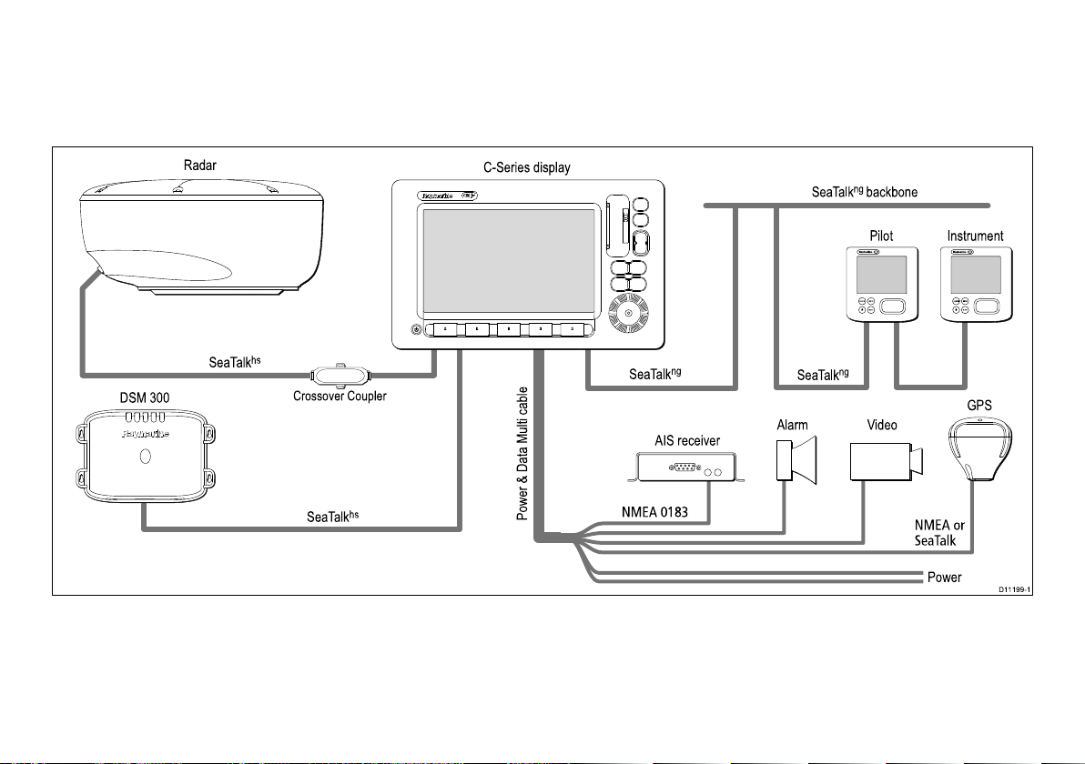
2.3C-Seriessystems
ENTERCANCEL
MENU
ENTERCANCEL
MENU
D11199-1
Pilot Instrument
SeaTalk
ng
backbone
SeaTalk
ng
SeaTalk
ng
SeaTalk
hs
SeaTalk
hs
DSM 300
Crossover Coupler
C-Series display
AIS receiver
Power & Data Multi cable
Radar
NMEA 0183
NMEA or
SeaTalk
GPS
Alarm
Power
Video
TheC-Seriesdisplaycanbeusedinanumberofsystemtypes.
Someexamplesareoutlinedhere.
Examplesystem
Planningtheinstallation
15
Page 16

C-Seriesprotocols
YourC-SeriesWidescreenMultifunctionDisplaycanconnectto
variousinstrumentsanddisplaystoshareinformationandso
improvethefunctionalityofthesystem.Theseconnectionsmaybe
madeusinganumberofdifferentprotocols.Fastandaccuratedata
collectionandtransferisachievedbyusingacombinationofthe
followingdataprotocols:
•SeaT alk
•SeaT alk
•NMEA2000
•SeaT alk
•NMEA0183
Note:Y oumayndthatyoursystemdoesnotuseallofthe
connectiontypesorinstrumentationdescribedinthissection.
hs
ng
SeaTalk
ng
utilizesasinglebackbonecabletowhichcompatible
instrumentsconnectusingaspur.Dataandpowerarecarriedwithin
thebackbone.Devicesthathavealowdrawcanbepoweredfrom
thenetwork,althoughhighcurrentequipmentwillneedtohavea
separatepowerconnection.
SeaTalk
CANbustechnology.CompatibleNMEA2000andSeaTalk/
SeaTalk
ng
isaproprietaryextensiontoNMEA2000andtheproven
2
devicescanalsobeconnectedusingtheappropriate
interfacesoradaptorcablesasrequired.
NMEA2000
NMEA2000offerssignicantimprovementsoverNMEA0183,most
notablyinspeedandconnectivity .Upto50unitscansimultaneously
transmitandreceiveonasinglephysicalbusatanyonetime,
witheachnodebeingphysicallyaddressable.Thestandard
wasspecicallyintendedtoallowforawholenetworkofmarine
electronicsfromanymanufacturertocommunicateonacommon
busviastandardizedmessagetypesandformats.
SeaTalk
SeaTalk
hs
hs
isanethernetbasedmarinenetwork.Thishighspeed
protocolallowscompatibleequipmenttocommunicaterapidlyand
sharelargeamountsofdata.
InformationsharedusingtheSeaT alk
hs
networkincludes:
•Sharedcartography(betweencompatibledisplays.
•Digitalradardata.
•Sonardata.
Seatalk
SeaTalk
ofcompatiblemarineinstrumentsandequipment.Itreplacesthe
olderSeaT alkandSeaTalk
ng
ng
(NewGeneration)isanenhancedprotocolforconnection
2
protocols.
SeaTalk
SeaTalkisaprotocolwhichenablescompatibleinstrumentsto
connecttoeachotherandsharedata.
TheSeaT alkcablesystemisusedtoconnectcompatible
instrumentsandequipment.Thecablecarriespoweranddataand
enablesconnectionwithouttheneedforacentralprocessor .
AdditionalinstrumentsandfunctionscanbeaddedtoaSeaT alk
system,simplybypluggingthemintothenetwork.SeaT alk
equipmentcanalsocommunicatewithothernon-SeaTalkequipment
viatheNMEA0183standard,providedasuitableinterfaceisused.
NMEA0183
TheNMEA0183DataInterfaceStandardwasdevelopedby
theNationalMarineElectronicsAssociationofAmerica.Itisan
internationalstandardtoenableequipmentfrommanydifferent
manufacturerstobeconnectedtogetherandshareinformation.
16C-SeriesWidescreeninstallation
Page 17

TheNMEA0183standardcarriessimilarinformationtoSeaT alk.
Howeverithastheimportantdifferencethatonecablewillonly
carryinformationinonedirection.ForthisreasonNMEA0183is
generallyusedtoconnectadatareceiverandatransmittertogether,
e.g.acompasssensortransmittingheadingtoaradardisplay.This
informationispassedin‘sentences’,eachofwhichhasathree
lettersentenceidentier.Itisthereforeimportantwhenchecking
compatibilitybetweenitemsthatthesamesentenceidentiersare
usedsomeexamplesofwhichare:
•VTG-carriesCourseandSpeedOverGrounddata.
•GLL-carrieslatitudeandlongitude.
•DBT-carrieswaterdepth.
•MWV-carriesrelativewindangleandwindspeeddata.
NMEAbaudrates
TheNMEA0183standardoperatesatanumberofdifferent
speeds,dependingupontheparticularrequirementorequipment
capabilities.Typicalexamplesare:
•4800baudrate.Usedforgeneralpurposecommunications,
includingFastHeadingdata.
•9600baudrate.UsedforNavtex.
•38400baudrate.UsedforAISandotherhighspeedapplications.
2.4Packcontents
Unpackthedisplayunitcarefullytopreventdamage.Savethe
cartonandpackingincasetheunithastobereturnedforservice.
Planningtheinstallation
17
Page 18
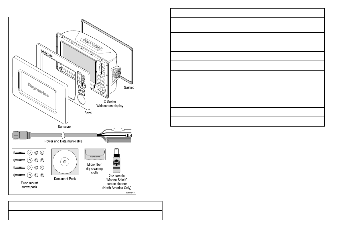
Allmodelscontainthefollowingitems:
D11194-1
Flush mount
screw pack
Power and Data multi-cable
C-Series
Widescreen display
Bezel
Suncover
Gasket
Document Pack
Micro fiber
dry cleaning
cloth
2oz sample
“Marine Shield”
screen cleaner
(North America Only)
SHI ELD
MARINE
Description
Bezel
Gasket
Suncover
1.5m(4.9ft)Poweranddatacable
Screwpack
Documentpack,includes:
•MultilingualCD
•Installationinstructions
•Cuttingtemplate
Microbercleaningcloth
Marineshieldscreencleansample(NorthAmericaonly)
Description
C-SeriesWidescreenMultifunctionDisplay
18C-SeriesWidescreeninstallation
Page 19
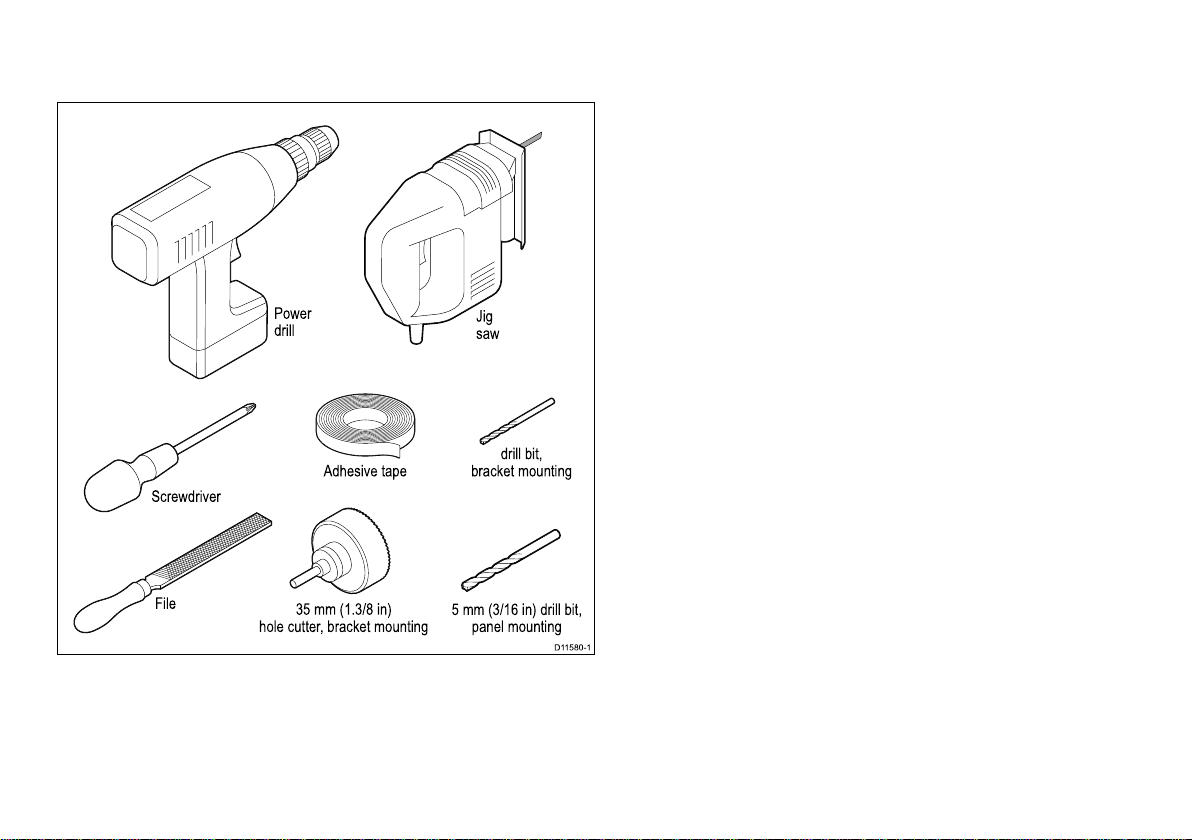
2.5Tools
D11580-1
Adhesive tape
Power
drill
Jig
saw
File
5 mm (3/16 in) drill bit,
panel mounting
35 mm (1.3/8 in)
hole cutter, bracket mounting
drill bit,
bracket mounting
Screwdriver
Toolsrequiredforinstallation
Planningtheinstallation
19
Page 20

20C-SeriesWidescreeninstallation
Page 21

Chapter3:Cablesandconnections
Chaptercontents
•3.1Generalcablingguidanceonpage22
•3.2Connectionsoverviewonpage23
•3.3Powerconnectiononpage23
•3.4SeaT alk
•3.5NMEA0183connectiononpage32
•3.6SeaT alkconnectiononpage33
•3.7Alarmconnectiononpage34
•3.8GPSconnectiononpage35
•3.9AISconnectiononpage36
•3.10Fastheadingconnectiononpage36
•3.11SeaT alk
•3.12NMEA2000connectiononpage38
•3.13Videoconnectiononpage39
hs
networkonpage26
ng
connectionsonpage37
Cablesandconnections
21
Page 22
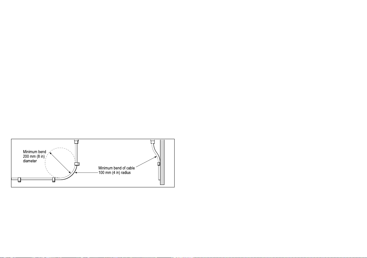
3.1Generalcablingguidance
Minimum bend of cable
100 mm (4 in) radius
Minimum bend
200 mm (8 in)
diameter
Cabletypesandlength
Itisimportanttousecablesoftheappropriatetypeandlength
•Unlessotherwisestateduseonlystandardcablesofthecorrect
type,suppliedbyRaymarine.
•Ensurethatanynon-Raymarinecablesareofthecorrectquality
andgauge.Forexample,longerpowercablerunsmayrequire
largerwiregaugestominimizevoltagedropalongtherun.
Routingcables
Cablesmustberoutedcorrectly,tomaximizeperformanceand
prolongcablelife.
•DoNOTbendcablesexcessively.Whereverpossible,ensurea
minimumbendradiusof100mm.
•Protectallcablesfromphysicaldamageandexposuretoheat.
Usetrunkingorconduitwherepossible.DoNOTruncables
throughbilgesordoorways,orclosetomovingorhotobjects.
•Securecablesinplaceusingtie-wrapsorlacingtwine.Coilany
extracableandtieitoutoftheway.
•Whereacablepassesthroughanexposedbulkheadordeckhead,
useasuitablewatertightfeed-through.
22
•DoNOTruncablesneartoenginesoruorescentlights.
Alwaysroutedatacablesasfarawayaspossiblefrom:
•otherequipmentandcables,
•highcurrentcarryingacanddcpowerlines,
•antennae.
Strainrelief
Ensureadequatestrainreliefisprovided.Protectconnectorsfrom
strainandensuretheywillnotpulloutunderextremeseaconditions.
Circuitisolation
Appropriatecircuitisolationisrequiredforinstallationsusingboth
ACandDCcurrent:
•Alwaysuseisolatingtransformersoraseparatepower-inverter
torunPC’s,processors,displaysandothersensitiveelectronic
instrumentsordevices.
•AlwaysuseanisolatingtransformerwithWeatherFAXaudio
cables.
•AlwaysuseanRS232/NMEAconverterwithopticalisolationon
thesignallines.
•AlwaysmakesurethatPC’sorothersensitiveelectronicdevices
haveadedicatedpowercircuit.
Cableshielding
Ensurethatalldatacablesareproperlyshieldedthatthecable
shieldingisintact(e.g.hasn’tbeenscrapedoffbybeingsqueezed
throughatightarea).
C-SeriesWidescreeninstallation
Page 23
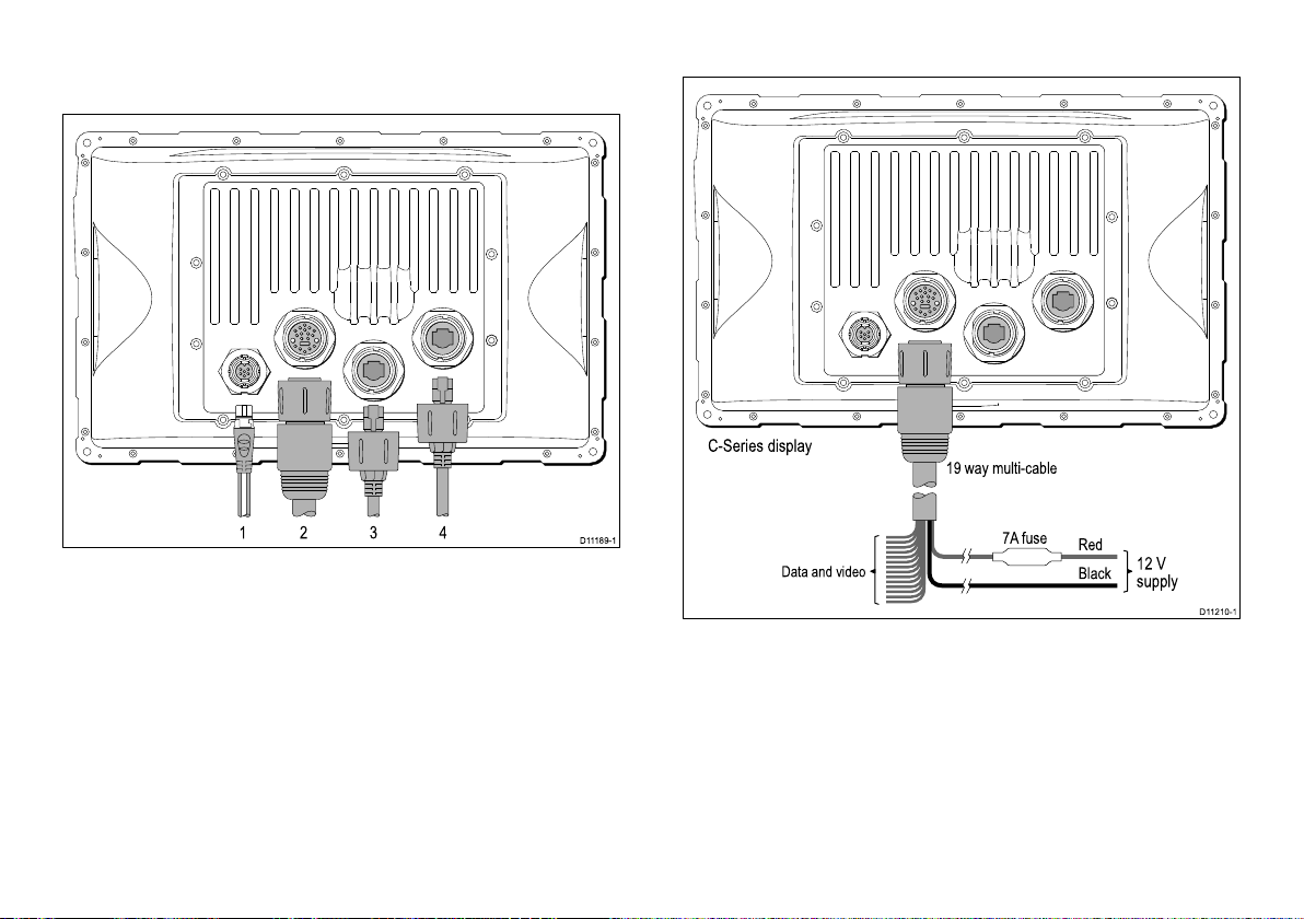
3.2Connectionsoverview
1 2 3 4
D11189-1
C-Series display
19 way multi-cable
Red
7A fuse
Black
12 V
supply
Data and video
D11210-1
Cableconnectorsareontherearofthedisplay
3.3Powerconnection
1.SeaTalk
ng
2.Poweranddata
3.SeaTalk
4.SeaTalk
hs
hs
Powerdistribution
Raymarinerecommendthatallpowerconnectionsaremadeviaa
distributionpanel.
•Allequipmentmustbepoweredfromabreakerorswitch,with
appropriatecircuitprotection.
•Allequipmentshouldwherepossiblebewiredtoindividual
Cablesandconnections23
breakers.
Page 24
Warning:Grounding
Thisdisplayisnotintendedforuseon“positive”
groundboats.Thepowerinputcabledrainwiresmust
beconnecteddirectlytotheboatsground.
Grounding
ThefollowingrequirementsapplywhengroundingRaymarine
equipment:
•Useadedicatedearthingplate(e.g.dynaplate)incontactwith
thewater.
•Groundcablesmayberoutedtoacommonpoint(e.g.withinthe
switchpanel.Withasingle(appropriatelyrated)copperbraid
connectingtotheearthingplate.
•Useattinnedcopperbraid,30Arating(1/4inch)orgreater.
Equivalentstrandedwirediameter4mmorgreater.
•Keepthelengthoftheearthbraidasshortaspossible.
Powercable
TheC-Seriesdisplayissuppliedwithacombinedpoweranddata
multicable,thiscanbeextendedifrequired.
Powercablesupplied
CablePartnumberNotes
1.5m(4.9ft)Powerand
datacable
R62131
SuppliedwithC-Series
unit
•Cablemustbeofasuitablegaugeforthecircuitload.
•Eachunitshouldhaveitsowndedicatedpowercablewiredback
tothedistributionpanel.
Totallength(max)Supplyvoltage
0–5m(0–16.4ft)
5–10m(16.4–32.8ft)
10–15m(32.8–49.2ft)
15–20m(49.2–65.5ft)
Note:Thesedistancesarefora2wirepowercablerunfromthebatteryto
thedisplay(approximatelythedistancefromthebatterytothedisplay).T o
calculatetheroundtriplength,doublethegurestatedhere.
12V18
24V20
12V14
24V18
12V12
24V16
12V12
24V14
Cablegauge
(AWG)
Breakers,fusesandcircuitprotection
TheC-SeriesWidescreenpowercableincludesanin-linefuse.You
canuseanadditionalthermalbreakerorfuseatthedistribution
panelifyouwish.
Cableextension
Thefollowingrestrictionsapplytoanyextensiontothepowercable:
24
C-SeriesWidescreeninstallation
Page 25
DisplayFuse
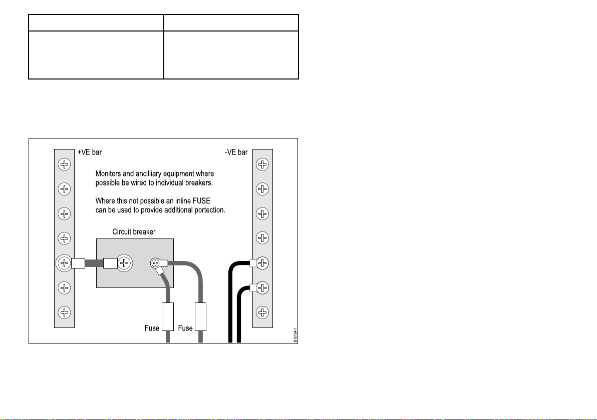
D10164-1
+VE bar
Circuit breaker
FuseFuse
Monitors and ancilliary equipment where
possible be wired to individual breakers.
Where this not possible an inline FUSE
can be used to provide additional portection.
-VE bar
•C90W
•C120W
7Ain-linefusettedwithinpower
cable.
•C140W
Sharingabreaker
Wheremorethan1pieceofequipmentsharesabreakeryoumust
provideprotectionfortheindividualcircuits.E.g.anin-linefusefor
eachpowercircuit
Cablesandconnections25
Page 26

3.4SeaTalk
D11214-1
SeaTalk
ng
SeaTalk
hs
SeaTalk
hs
SeaTalk
hs
Master C-Series display C-Series display
DSM300
Multi cable
POWER
Radar
POWER
SeaTalk
NMEA0183
Alarm buzzer output
Video input
Multi cable
Crossover Coupler
hs
network
TheSeaTalk
hs
networkallowsyoutonetworkcompatibledisplays
andotherdigitaldevices.
TheC-SeriesWidescreenDisplaycanuseSeaT alk
hs
toconnectto:
•AnotherC-SeriesWidescreenDisplay.
•Adigitalradarscanner.
•ADSM300orDSM30sonarmodule.
•ASeaTalk
TypicalSeaTalk
26C-SeriesWidescreeninstallation
hs
switch.
hs
network
Page 27
SeaTalk
hs
displaytodisplaycables
Radarconnection
Youcanconnectupto2C-SeriesWidescreendisplaystogether
usingSeaTalk
hs
.ConnectthedisplaysdirectlyoruseaSeaTalk
switch.
hs
SeaTalk
ConnectfromtheSeaTalk
networkcables
hs
switchintotherearofthedisplay.
CablePartnumberNotes
hs
1.5m(4.9ft)SeaT alk
E55049
networkcable
hs
5m(16.4ft)SeaTalk
E55050
networkcable
hs
10m(32.8ft)SeaTalk
E55051
networkcable
20m()SeaTalk
hs
E55052
networkcable
FullywaterproofSeaTalk
hs
networkcables
Connectdirectlyfromdisplaytodisplay .
CablePartnumberNotes
1.5m(4.9ft)Dualend
hs
SeaTalk
15m(49.2ft)Dualend
SeaTalk
networkcable.
hs
networkcable
A62245
A62246
Cablehaswaterproof
connectorsatbothends.
Cablehaswaterproof
connectorsatbothends.
hs
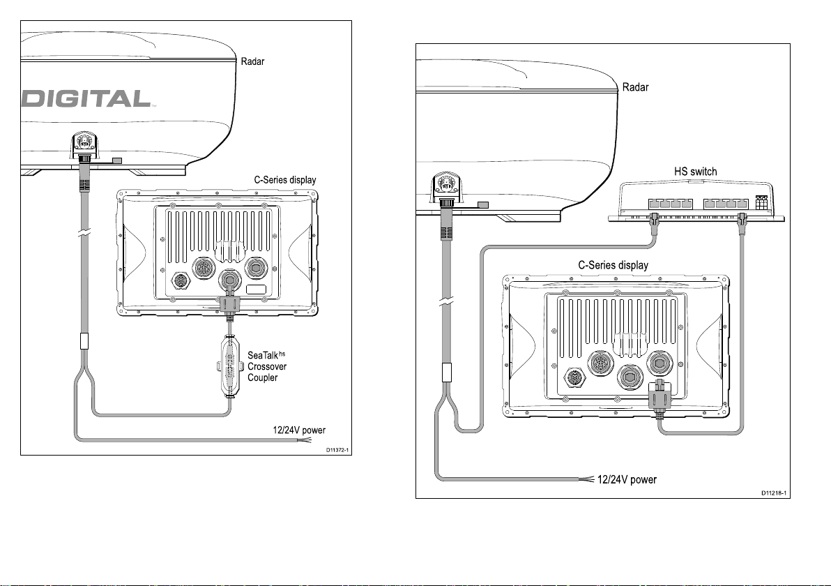
C-SeriesWidescreendisplaysarecompatiblewithRaymarinedigital
radarscanners.ThescannerisconnectedusingaSeaT alk
ThedigitalradarcanbeconnectedeitherdirectlytotheC-Series
displayorviaaSeaT alk
hs
switch.
hs
cable.
RadarconnecteddirectlytotheC-Seriesunit
Note:Theconnectoronthefreeendoftheradarcabledoesnot
havealocking/weathertightmechanism.Theuseofacrossover
couplerisimportanttocreateaweatherproofconnection.
Cablesandconnections
27
Page 28
C-Series display
Radar
D11372-1
SeaTalk
hs
Crossover
Coupler
12/24V power
HS switch
C-Series display
Radar
D11218-1
12/24V power
RadarconnectedusingSeaTalk
hs
switch
28C-SeriesWidescreeninstallation
Page 29

Digitalradarcables
Youwillneedatleast2cablestoconnectthedigitalradarscanner .
OnecableconnectsthescannertoaSeaT alk
hs
switch(orcross
overcoupler).Thesecondcablethenconnectsintothedisplay.
Note:Themaximumcablelengthincludingallextensionsis25m
(82ft).
RadarscannertoSeaT alk
hs
switch(orcrossovercoupler)
Digitalscannercables
ConnecttheRadarscannertotheSeaT alk
hs
switch(orcrossovercoupler)and
powersupply.Thesecablescontainbothpoweranddatawires.
CablePartnumberNotes
5m(16.4ft)Digitalcable
10m(32.8ft)Digital
cable
A55076
A55077Yourradarscannermay
includethe10mcable
(dependinguponthe
modelpurchased)
15m(49.2ft)Digital
A55078
cable
25m(82.0ft)Digital
A55079
cable
Extensioncables
UseofoneofthesecablestoextendtheradarconnectiontotheSeaTalk
hs
switch
(orcrossovercoupler)andpowersupply.Thesecablescontainbothpowerand
datawires.
CablePartnumberNotes
2.5m(8.2ft)extension
A92141
cable
5m(16.4ft)extension
A55080
cable
10m(32.8ft)extension
A55081
cable
SeaTalk
SeaTalk
ConnectfromtheSeaT alk
hs
switch(orcrossovercoupler)todisplayunit
hs
networkcables
hs
switchorthecrossovercouplerintotherearofthe
display.
CablePartnumberNotes
hs
1.5m(4.9ft)SeaT alk
E55049
networkcable
hs
5m(16.4ft)SeaTalk
E55050
networkcable
hs
10m(32.8ft)SeaTalk
E55051
networkcable
hs
20m(65.6ft)SeaTalk
E55052
networkcable
SeaTalk
hs
hardware
ToconnectthedigitalradartotheC-Seriesdisplayyouwillneed
toincludeoneofthefollowing
Cablesandconnections29
Page 30

CablePartnumberNotes
D11219-1
DSM300
C-Series display
SeaTalk
hs
hs
SeaTalk
SeaTalk
switch
hs
coupler
E55058
E55060
8wayhubfornetwork
connectionofmultiple
SeaTalk
Coupleforconnection
hs
devices.
ofasingleSeaT alk
device.
Sonarconnection
Thesonarconnectionisrequiredforshnderapplications.The
C-Seriesdisplayisconnectedtoasonarmodule(DSM)usinga
SeaTalk
connectedtotheDSMunit.
hs
cable.Youwillalsorequireacompatibletransducer
hs
TheC-SeriesdisplaycanbeusedwiththefollowingDSMunits
•DSM300
•DSM30
TheC-Seriescansupport1DSMmodule
30C-SeriesWidescreeninstallation
Page 31

TypicalDSMsystem
Transducer
DSM300
D11584-1
C Series Display Unit
SeaTalk
hs
Cable
CablePartnumberNotes
hs
10m(32.8ft)SeaTalk
E55051
networkcable
hs
20m(65.6ft)SeaTalk
E55052
networkcable
Sonarcable
ConnecttheDSMunitdirectlytoyourdisplay ,orconnectviathe
SeaTalk
SeaTalk
ConnectfromtheSeaTalk
hs
hs
switch.
networkcables
hs
switchintotherearofthedisplay.
CablePartnumberNotes
hs
1.5m(4.9ft)SeaT alk
E55049
networkcable
hs
5m(16.4ft)SeaTalk
E55050
networkcable
FullywaterproofSeaTalk
hs
networkcables
ConnectdirectlyfromDSMtotherearofthedisplay.
CablePartnumberNotes
hs
1.5m(4.9ft)SeaT alk
A62245
networkcable.
hs
10m(32.8ft)SeaTalk
A62246
networkcable
Cablehaswaterproof
connectorsatbothends.
Cablehaswaterproof
connectorsatbothends.
Cablesandconnections31
Page 32

3.5NMEA0183connection
White
IN
+ve
Green
IN
-ve
Yellow
OUT
+ve
OUT
+ve
OUT
-veIN+ve
Brown
OUT
-ve
IN
-ve
Orange/
White
IN
+ve
Orange/
Green
IN
-ve
Orange/
Yellow
OUT
+ve
OUT
+ve
OUT
-veIN+ve
Orange/
Brown
OUT
-ve
IN
-ve
NMEA
DEVICE
4800 baud
(transmit to
C-Series
only)
C-Series display
NMEA
DEVICE
4800/9600 baud
NMEA
DEVICE
4800/9600/38400 baud
Blue/
White
IN
+ve
Blue/
Green
IN
-ve
OUT
+ve
OUT
-ve
D11200-1
ConnectionstoNMEA0183devicesaremadeusingthesupplied
Poweranddatacable.
TheC-Serieshas3NMEAportsavailable:
•Port1:Inputandoutput,4800/9600baudrate.
•Port2:Inputandoutput,upto38400baudrate.
•Port3:Inputonly,4800baudrate.
NMEA0183cable
YoucanextendtheNMEA0183wireswithinthesuppliedpower
anddatacable.
Datacableextension
ThefollowingrestrictionsapplytoanyextensiontotheNMEA0183datawires.
Totallength(max)Cable
Upto5mHighqualitydatacable:
•2xtwistedpairwithoverallshield.
•50to75pF/mcapacitancecoreto
core.
32C-SeriesWidescreeninstallation
Page 33

3.6SeaTalkconnection
C-Series display
19 way multi-cable
D11215-1
White/Red
White/Black
White/Yellow
Black
Red
Yellow
5 A fused,
12 V dc supply
SeaTalk devices
Power, data and video
ConnectionstoSeaT alkequipmentaremadeusingthesupplied
multi-cable.
SeaTalkcable
ForSeaTalkcablesandextensions,useRaymarineSeaT alkcable
accessories.
Note:PowertoSeaT alkinstrumentsisnotprovidedbythe
C-SeriesWidescreenDisplay.
Cablesandconnections33
Page 34

3.7Alarmconnection
C-Series display
Red
Black
Black
Alarm
Grey
Black
D11216-1
-ve supply
(from battery/
breaker)
19 way multi-cable
Power, data and video
Analarmbuzzercanbeconnectedusingthepower/datacable
providedwiththedisplay .
Typicalalarmconnection
Note:Thealarmoutputisratedfor100mAmaximumload
34C-SeriesWidescreeninstallation
Page 35

Highalarmloadsandthirdpartyalarms
High current load
Battery +
Battery --
0v return
Relay
Suppression
diode
Alarm out
(+ve)
D11591-1
3.8GPSconnection
Youcanusethealarmoutputtoswitcharelay.Thismaybeuseful
forconnectinghighloadssuchasthirdpartyalarmsoundersor
inductiveloadstotheC-Seriesmultifunctiondisplay.Ifyouarein
anydoubtastohowtomakesuchconnectionspleaseconsultan
authorizedinstaller.
TheC-Seriesmultifunctiondisplayhasapositiveswitchedalarm
output.Thefollowingcircuitshowsthearrangementforconnection
ofarelayswitch.
Alarmoutputconguredtoswitcharelay
Note:Whenconnectingtheoutputtoarelayorotherinductive
deviceyoushouldtaspikesuppressiondiodee.g.1N4001.
DependinguponyourGPStypeitmaybeeitherconnectedvia
SeaTalkorNMEA0183.
Seealso
•ForSeaTalkconnectionreferto:3.6SeaT alkconnection.
•ForNMEA0183connectionreferto:3.5NMEA0183connection.
Cablesandconnections35
Page 36

3.9AISconnection
D11221-1
AIS receiver
VHF radio
VHF antenna
NMEA 0183 (4800)
e.g.fast heading
NMEA0183 (38400)
VHF (antenna signal)
C Series display
NMEA 0183 (4800)
e.g GPS data to VHF radio
D11220-1
ENTERCANCEL
MENU
C Series display
NMEA0183
Autopilot
Pilot control head Fluxgate compass
3.10Fastheadingconnection
AcompatibleAIScanbeconnectedusingNMEA0183.
Fastheadingdatarequiredforradartargetacquisition(MARPA)may
comefromeithertheautopilotoraseparateRaymarineFastheading
sensor.
TypicalfastheadingfromNMEA0183compatibleautopilot
Note:TheconnectioncanbemadeintoanyNMEA0183port.
36C-SeriesWidescreeninstallation
Page 37

3.11SeaTalk
C Series
Display
Depth
Transducer
Speed
Transducer
Wind
Transducer
Transducer
Pod
Transducer
Pod
ST70
Instrument
ST70
Pilot Controller
Transducer
Pod
Autopilot
(Course
Computer)
12 V / 24 V dc
12 V dc + Data
D11195-1
ENTERCANCEL
MENU
ENTERCANCEL
MENU
Power Supply
SeaTalk
ng
backbone
ng
connections
TypicalSeaTalk
ng
system
TheC-SeriesWidescreenDisplaycanconnectaspartofa
SeaTalk
TheC-SeriescanuseSeaT alk
•SeaT alk
•SeaT alk
ng
computer)
network.
ng
tocommunicatewith:
ng
instruments(e.g.ST70)
ng
autopilots(e.g.ST70withSmartPilotSPXcourse
Cablesandconnections37
Page 38

SeaTalk
SeaTalk
ng
to DeviceNet cable
SeaTalk
ng
backbone
NMEA 2000
equipment
(e.g. engine via
appropriate
manufacturers
interface)
D11198-1
SeaTalk
ng
cabling
ng
cables
Connection/CableNotes
Backbonecables(variouslengths)Themaincablecarryingdata.Spurs
fromthebackboneareusedto
connectSeaTalk
ng
devices.
T-piececonnectorsUsedtomakejunctionsinthe
backbonetowhichdevicescanthen
beconnected.
Terminators
Requiredateitherendofthe
backbone.
Spurcables
Usedtoconnectdevices.Devices
maybedaisychainedorconnected
directlytotheT-pieces.
3.12NMEA2000connection
NMEA2000devicesareconnectedusingtheSeaT alk
displaycanreceivedatafromNMEA2000devices(e.g.datafrom
compatibleengines).YoumayconnectNMEA2000compatible
devicesusingappropriateadaptorcables
ng
bus.The
Seatalk
TheSeaT alk
ng
power
ng
busrequiresa12Vpowersupply.Thismaybe
providedfrom:
•Raymarineequipmentwitharegulated12Vsupply .(e.g.a
SmartPilotSPXcoursecomputer)
•Othersuitable12Vsupply .
Note:SeaT alk
ng
doesNOTsupplypowertomultifunctiondisplays
andotherequipmentwithadedicatedpowersupplyinput.
38C-SeriesWidescreeninstallation
Page 39

3.13Videoconnection
C-Series display
19 way
multi-cable
Power, data and video
BNC
D11222-1
TheC-Serieshasaninputforconnectionofcamerasorother
typesofvideoequipment.Thevideoconnectionismadeusing
thecombinedpoweranddatacablesuppliedwiththeunit.The
connectioniscompatiblewithNTSCandPALequipment.
Videoconnection
Cablesandconnections39
Page 40

40C-SeriesWidescreeninstallation
Page 41

Chapter4:Locationandmounting
Chaptercontents
•4.1Selectingalocationonpage42
•4.2Flushmountingonpage45
•4.3Bracket(trunnion)mountingonpage46
•4.4Frontbezelonpage48
Locationandmounting
41
Page 42

4.1Selectingalocation
Warning:Potentialignitionsource
ThisproductisNOTapprovedforusein
hazardous/ammableatmospheres.DoNOTinstallin
ahazardous/ammableatmosphere(suchasinan
engineroomornearfueltanks).
Generallocationrequirements
Whenselectingalocationforyourdisplayitisimportanttoconsider
anumberoffactors.
Keyfactorswhichcanaffectproductperformanceare:
•Ventilation
Toensureadequateairow:
–Ensurethatequipmentismountedinacompartmentofsuitable
size.
–Ensurethatventilationholesarenotobstructed.Allow
adequateseparationofequipment.
Anyspecicrequirementsforeachsystemcomponentare
providedlaterinthischapter.
•Mountingsurface.
Ensureequipmentisadequatelysupportedonasecuresurface.
Donotmountunitsorcutholesinplaceswhichmaydamagethe
structureofthevessel.
•Cableentry
Ensuretheunitismountedinalocationwhichallowsproper
routingandconnectionofcables:
–Minimumbendradiusof100mm(3.94in)unlessotherwise
stated.
–Usecablesupportstopreventstressonconnectors.
•Wateringress
Thedisplayissuitableformountingbothaboveandbelowdecks.
ItiswaterprooftoIPX6standard.Althoughtheunitiswaterproof,
itisgoodpracticetolocateitinaprotectedareaawayfrom
prolongedanddirectexposuretorainandsaltspray.
•Viewingangle
ThecontrastandcolorsseenonallLCDunitsvariesslightlywith
viewingangleandarebestviewedperpendiculartothedisplay .
Avoidlocationswhereexcessivereectionwilloccurinnormaluse
•Electricalinterference
Selectalocationthatisfarenoughawayfromdevicesthat
maycauseinterference,suchasmotors,generatorsandradio
transmitters/receivers.
•Magneticcompass
Selectalocationthatisatleast3ft(1m)awayfromamagnetic
compass.
•Powersupply
42
C-SeriesWidescreeninstallation
Page 43

Selectalocationthatisascloseaspossibletotheboat’sDC
C90W, C120W and C140W dimensions
D11190-1
B
E
A
D
C
Model
C90
12.45 in
(316 mm)
A
7.74 in
(197 mm)
B
4.43 in
(113 mm)
C
6.14 in
(156 mm)
D
8.3 in
(211 mm)
C120
14.97 in
(380 mm)
10.0 in
(245 mm)
4.43 in
(113 mm)
6.14 in
(156 mm)
10.2 in
(260 mm)
C140
16.66 in
(423 mm)
10.9 in
(277 mm)
4.43 in
(113 mm)
6.14 in
(156 mm)
11.46 in
(291 mm)
E
powersource.Thiswillhelptokeepcablerunstoaminimum
C-SeriesWidescreendimensions
Mountinglocation
•AboveDecksmounting.
ProvidesoptimalGPSperformance.(Forequipmentwith
appropriatewaterproofrating.)
•BelowDecksmounting.
ProvidesgoodperformancewithGRPconstructionvessels,
howeverGPSmaybelesseffectiveinpoorprevailingconditions.
Note:Belowdecksmountingonvesselsofnon-GRPconstruction
mayrequireanexternalGPSmountedabovedecks.
InternalGPSenvironment
Inadditiontogeneralguidelinesconcerningthelocationofmarine
electronics,thereareanumberofenvironmentalfactorstoconsider
wheninstallingequipmentwithaninternalGPSantenna.
Locationandmounting
43
Page 44

TypicallocationsandGPSperformance
Optimal GPS performance (above decks)
GPS performance affected by prevailing conditions
Not recommended
D11537-1
bulkhead,ortheinterioroflargervesselsmayresultinareduced
GPSsignal.
•Otherconstructions.GPSperformancemaybeadversely
affectedbelowdecks.Seekprofessionalassistanceandconsider
useofanexternalGPSantennamountedabovedecks.
Prevailingconditions
TheweatherandlocationoftheboatcanaffecttheGPS
performance.Typicallycalmclearconditionsprovideforamore
accurateGPSx.Vesselsatextremenortherlyorsoutherlylatitudes
mayalsoreceiveaweakerGPSsignal.GPSantennamounted
belowdeckswillbemoresusceptibletoperformanceissuesrelated
totheprevailingconditions.
Vesselconstruction
•GRPvessels.Unitcanbemountedaboveandbelowdecks.
Althoughtheproximityofheavystructuresuchasastructural
44
C-SeriesWidescreeninstallation
Page 45

4.2Flushmounting
D11193-1
ThestandardmethodformountingaC-Seriesdisplayisaush
orpanelmountingarrangement.
Beforemountingtheunit,ensurethatyouhave:
•Selectedasuitablelocation
•Identiedthecableconnectionsandroutethatthecableswilltake
•Detachedthefrontbezel
Locationandmounting
1.Checktheselectedlocationfortheunit.Aclear,atareawith
suitableclearancebehindthepanel,isrequired.
2.Fixtheappropriatecuttingtemplatesuppliedwiththeproduct,to
theselectedlocation,usingmaskingorself-adhesivetape.
3.Usingasuitableholesaw(thesizeisindicatedonthetemplate),
makeapilotholeineachcornerofthecut-outarea.
4.Usingasuitablesaw,cutalongtheinsideedgeofthecut-outline.
45
Page 46

5.Ensurethattheunittsintotheremovedareaandthenle
aroundthecutedgeuntilsmooth.
6.Drillfour4.5mm(3/16in)holesasindicatedonthetemplate
toacceptthesecuringbolts.
7.Placethegasketontothedisplayunitandpressrmlyontothe
ange.
8.Connectthepower ,dataandothercablestotheunit.
9.Slidetheunitintoplaceandsecureusingboltsprovided.
Onceyouhavesecuredthedisplayinplace,proceedandattach
thefrontbezel.
Fixingbolts
Whenushmountingyourdisplayitisimportanttouseboltsof
anappropriatelength.Thelengthusedisdependantuponthe
thicknessofthemountingsurface.
Thickness(mm)Boltlength(mm)
<312
3–716
7–1120
11–1524
15–1928
19–2332
4.3Bracket(trunnion)mounting
TheC-Serieswidescreendisplaycanbemountedonanoptional
bracket.
REQUIRESTHEOPTIONALMOUNTINGBRACKETACCESSORY .
Beforemountingtheunitensurethatyouhave:
•Selectedasuitablelocation
•Identiedthecableconnectionsandroutethatthecableswilltake
•Attachedthefrontbezel
46C-SeriesWidescreeninstallation
Page 47

D11191-1
Note:Bracket(trunnion)mountingkitisavailableasanoptional
accessory.
1.Markthelocationofthemountingbracketscrewholesonthe
chosenmountingsurface.
2.Drillpilotholesforthescrewsusingasuitabledrill,takingcare
thattherearenocablesoranythingthatmaybedamaged
behindthesurface.
3.Usethescrewssuppliedtoattachthemountingbracketsecurely .
4.FitthetrimringtotherearofthedisplayusingtheM4bolts
supplied.
5.Attachthedisplayunittothemountingbracket.
Onceyouhavesecuredthedisplayinplace,proceedandmake
therequiredcableconnections.
Locationandmounting
47
Page 48

4.4Frontbezel
D11196-1
Clip recess
Attachingthefrontbezel
Beforettingthebezelyoumusthavemountedtheunitinits
requiredlocation.
1.Carefullyliftoneedgeofthescreenprotectionlm,sothatitis
accessibleforremovingwhenunitinstallationiscomplete.
2.PlacethebezeloverthefrontoftheC-SeriesDisplay,ensuring
thatlockinglugslocatedatthebottomedgeofthebezelare
latchedintoposition.
3.Ensurethatthecontrolbuttonspassthroughtheirrespective
openings.
4.Applyrmbutevenpressuretothebezelalongthe:
i.Outeredges-workfromthesidesupwardsandthenalong
thetopedge,toensurethatitclipssecurelyintoposition.
ii.Inneredges-particularlyalongthechartcarddooredge,to
ensurethatthebezelsitsat.
48C-SeriesWidescreeninstallation
Page 49

5.Checkthatallcontrolbuttonsarefreetooperate.Itissuggested
D11197-1
thatyouuseyourthumborforengerinacircularmotiontodo
this.
Removingthefrontbezel
1.Whenremovingthebezel,startatthebottom-middleandwork
aroundtothesidesandtopedge.
Locationandmounting
49
Page 50

50C-SeriesWidescreeninstallation
Page 51

Chapter5:Systemchecks
Chaptercontents
•5.1Initialpowerontestonpage52
•5.2GPScheckonpage53
•5.3Radarcheckonpage54
•5.4Sonarcheckonpage56
•5.5Languageselectiononpage57
Systemchecks
51
Page 52

5.1Initialpowerontest
1
2
3
Note:Youcanchangetherequiredpagesetatanytimeduring
normaloperation.
UniControl
TheUniControlprovidesanumberofkeyfunctionsinasingle
control.
1.RotaryControl.Usethistoselectmenuoptionsandadjustthe
valueofvariousitems.
2.Trackpad.Usethistoselectmenuitems,optionsandmove
thecursor.
3.OKbutton.Usethistoconrmaselectionorentry.
Poweringthedisplayon
1.PressandholdthePOWERbuttonuntiltheRaymarinelogo
appears.
2.PressOKtoacknowledgethewarningwindow.
Selectapageset
Selectingapageset
Toselectapagesetatrsttimepoweron:
1.UsetheUniControltoselecttherequiredsetofpages.
2.PressOK.
Whenyourstturnthedisplayonyouwillbepromptedtoselecta
pagesetfromthoseavailable.
52C-SeriesWidescreeninstallation
Page 53

5.2GPScheck
CheckingGPSoperation
YoucancheckthattheGPSisfunctioningcorrectlyusingthechart
application.
1.PressthePAGEbuttontoshowtheavailablepagesinthe
toolbar.
2.PressthePAGEbuttontoswitchbetweentheavailablepages.
3.PressOKwhenthechartisdisplayed.
Note:Asolidcircleonthechartindicatesthatneitherheading
norCourseOverGround(COG)dataisavailable.
4.Checkthescreen.
Withthechartdisplayed,youshouldsee:
Yourboatposition(indicatesaGPSx).Yourcurrentposition
isrepresentedbyaboatsymbolorsolidcircle.Yourpositionis
alsodisplayedinthedatabarunderVESPOS.
Systemchecks
53
Page 54

5.3Radarcheck
Checkingtheradar
TypicalHDdigitalradarscreen
Warning:Radarscannersafety
Beforerotatingtheradarscanner,ensureallpersonnel
areclear.
Warning:Radartransmissionsafety
Theradarscannertransmitselectromagneticenergy.
Ensureallpersonnelareclearofthescannerwhen
theradaristransmitting.
1.SelectaRadarpage:
•PressthePAGEbuttontoselectfromthecurrentpageset.
•PressandholdthePAGEbuttontoselectfromallavailable
pages.
TheRadarscannerswillnowinitializeinstandbymode,this
processwilltakeapproximately70seconds.
2.PressthePOWERbutton.
3.PresstheRadarTx/StdbysoftkeyandsettoTx.
Thescannersshouldnowbetransmittingandreceiving.
4.Checkthattheradarscreenisoperatingcorrectly .
54C-SeriesWidescreeninstallation
Note:Analogandnon-HDradarscreenswillhavedifferent
coloring/appearance.
Pointstocheck:
•Radarsweepwithechoresponsesareshownonscreen.
•Radarstatusiconrotatingintoprighthandcorner.
Checkandadjustbearingalignment
Bearingalignment
Theradarbearingalignmentensuresthatradarobjectsappearat
thecorrectbearingrelativetoyourboat’sbow.Youshouldcheck
thebearingalignmentforanynewinstallation.
Page 55

Examplemisalignedradar
Target object dead ahead
(bearing alignment will be required)
D11590-1
Radar target not aligned
Checkingthebearingalignment
1.Withyourvesselunderway:Alignthebowwithastationary
objectidentiedontheradardisplayAnobjectbetween1&2
NMdistantisideal.
2.Notethepositionoftheobjectontheradardisplay.Ifthetarget
isnotundertheshipsheadingmarker(SHM),thereisan
alignmenterrorandyouwillneedtocarryoutbearingalignment
adjustment.
Adjustingthebearingalignment
Onceyouhavecheckedthebearingalignmentyoucanproceedand
makeanyrequiredadjustments.
Withtheradarpagedisplayed:
1.Selectthebearingalignmentmenu.
2.PresstheBEARINGALIGNMENTsoftkey.
3.Usetherotarycontroltoplacetheselectedtargetunderthe
Ship’sHeadingMarker.
4.PressOKwhencomplete.
Adjustingradaroffset(parking)
Thissettingisapplicabletoopenarrayscanners.Itisusedto
ensurethescannerparksinthecorrectpositionwhenrotationstops.
Beforeyouproceed,ensurethat:
•Theradarpageisselected
•Theradarscannerisinitializedstandbymode
1.PresstheMENUbuttonandthenselecttheradarsetupmenu
(withtheradarinstandbymode).
2.SelectthePARKINGOFFSEToption,thenadjusttheoffset
anglerequiredtoparktheradarsothattheantennacomesto
restfacingforward(youshouldseetheRaymarinelogowording
fromthefrontofthevessel)whenyouplaceitineitherstandby
orswitchitoff.
3.PressOKwhencomplete.
Systemchecks
55
Page 56

5.4Sonarcheck
Warning:Sonaroperation
•NEVERoperatethesounderwiththeboatoutof
thewater.
•NEVERtouchthetransducerfacewhenthesounder
ispoweredon.
•SWITCHOFFthesounderifdiversarelikelytobe
within25ft(5m)ofthetransducer.
Selecttheshndertransducer
Youmustsetthesetupthesystemforthetransducerconnectedto
yourDSM.Usetheshndersetupmenustoselecttheappropriate
transducer.
Selectingtheshndertransducer
Fromthemainshnderscreen:
1.PresstheMENUbutton.
2.SelectFishnderSetupfromthelistofoptions.
3.SelectTransducerSettingsfromthelistofmenuoptions:
4.UsetheSelectTransduceroptionandselecttheappropriate
transducerfromthoseavailable.
3.PressOKwhentheshnderisdisplayed.
4.Checktheshnderscreen.
Withtheshnderactiveyoushouldsee:
•Depthreading(indicatesthetransducerisworking).The
depthisshowninlargewhitenumbersatthebottomleftof
thescreen.
Checkingthesonar
Sonarchecksaremadeusingtheshnderapplication.
1.PressthePAGEbuttontoshowtheavailablepagesinthe
toolbar.
2.PressthePAGEbuttontoswitchbetweentheavailablepages.
56C-SeriesWidescreeninstallation
Page 57

5.5Languageselection
TheC-Seriesmultifunctiondisplaycanoperateinthefollowing
languages:
English(US)English(UK)Chinese
DanishDutchFinnish
French
IcelandicItalianJapanese
KoreanNorwegianPortuguese
Russian
1.PresstheMENUbuttontoopenthesetupmenu.
2.Usethetrackpadup/downtoselecttheSystemSetupmenu.
3.Usethetrackpadrighttoopenthesub-menu.
4.UsethetrackpadtoselecttheLanguageoptions.
5.Selectfromthelanguagesavailable.
6.PressOKtoacceptandsavethechange.
7.PressOKagaintoreturnbackthroughthemenustothenormal
display.
GermanGreek
SpanishSwedish
Systemchecks
57
Page 58

58C-SeriesWidescreeninstallation
Page 59

Chapter6:Troubleshooting
Chaptercontents
•6.1Troubleshootingonpage60
•6.2Poweruptroubleshootingonpage60
•6.3Radartroubleshootingonpage61
•6.4GPStroubleshootingonpage62
•6.5Sonartroubleshootingonpage63
•6.6Systemdatatroubleshootingonpage64
•6.7SeaT alk
•6.8Miscellaneoustroubleshootingonpage66
hs
LEDindicationsonpage65
Troubleshooting
59
Page 60

6.1Troubleshooting
6.2Poweruptroubleshooting
Thetroubleshootinginformationprovidespossiblecausesand
correctiveactionrequiredforcommonproblemsassociatedwith
marineelectronicsinstallations.
AllRaymarineproductsare,priortopackingandshipping,subjected
tocomprehensivetestandqualityassuranceprograms.However,
ifyouexperienceproblemswiththeoperationofyourC-Series
multifunctiondisplay,thissectionwillhelpyoutodiagnoseand
correctproblemsinordertorestorenormaloperation.
Ifafterreferringtothissectionyouarestillhavingproblemswithyour
unit,pleasecontactRaymarineT echnicalSupportforfurtheradvice.
Problemsatpowerupandtheirpossiblecausesandsolutionsare
describedhere.
ProblemPossiblecausesPossiblesolutions
Thedisplaydoesnot
startup.
Problemwithpowerto
theunit.
Checkrelevantfuses
andbreakers.
Checkthatthepower
supplycableissound
andthatallconnections
aretightandfreefrom
corrosion.
Checkthatthepower
sourceisofthecorrect
voltageandsufcient
current.
60C-SeriesWidescreeninstallation
Page 61

6.3Radartroubleshooting
Problemswiththeradarandtheirpossiblecausesandsolutions
aredescribedhere.
ProblemPossiblecausesPossiblesolutions
NoDataorNoscanner
message.
Radarscannerpower
supply.
SeaTalk
hs
network
problem.
Softwaremismatch
betweenequipmentmay
preventcommunication.
Switchatscanner
pedestalinOFFposition.
Checkthatthescanner
powersupplycable
issoundandthatall
connectionsaretight
andfreefromcorrosion.
Checkrelevantfuses
andbreakers.
Checkpowersourceis
ofthecorrectvoltage
andsufcientcurrent
(usingvoltageboosterif
appropriate).
CheckthattheScanner
iscorrectlyconnected
tothedisplayviaa
crossovercoupleror
hs
SeaTalk
Checkthestatusofthe
SeaTalk
switch.
hs
Switch.
CheckthatSeaT alk
cablesarefreefrom
damage.
ContactRaymarine
technicalsupport.
Ensurescanner
pedestalswitchisin
ONposition.
hs
Troubleshooting
61
Page 62

ProblemPossiblecausesPossiblesolutions
Thebearingofatarget
ontheradarscreenis
incorrect.
Theradarbearing
alignmentrequires
correcting.
Checkandadjustradar
bearingalignment.
6.4GPStroubleshooting
ProblemswiththeGPSandtheirpossiblecausesandsolutions
aredescribedhere.
ProblemPossiblecausesPossiblesolutions
“NoFix”GPSstatus
iconisdisplayed.
Geographiclocationor
prevailingconditions
preventingsatellitex.
ExternalGPSantenna
conictwithinternal
GPS.
InternalGPSantenna
hasbeendisabled.
ExternalGPS
connectionfault.
Unitmountedinpoor
location.
Forexample:
•BelowdecksonSteel
constructionvessel.
•Closeproximity
totransmitting
equipmentsuchas
VHFradio.
ExternalGPSantennainEnsureGPSantenna
Checkperiodicallyto
seeifaxisobtained
inbetterconditionsor
anothergeographic
location.
DisableinternalGPS
fromwithinthesetup
menus.
EnableinternalGPS
fromwithinthesetup
menus.
EnsurethatGPS
connectionsandcabling
arecorrectandfault
free..
Ensurethattheunitis
mountedinaccordance
withtheinstructions.
62C-SeriesWidescreeninstallation
Page 63

poorposition.hasaclearviewofthe
sky.
GPSinstallation
problem.
Refertomanufacturers
handbookforinstallation
details.
Note:AGPSStatusscreenisavailablewithintheSetup
menu.Thisprovidessatellitesignalstrengthandotherrelevant
information.
6.5Sonartroubleshooting
Problemswiththesonarandtheirpossiblecausesandsolutions
aredescribedhere.
ProblemPossiblecausesPossiblesolutions
Nodatasourceforthe
shnder.
DSMpowersupplyfault.ChecktheDSMpower
OtherDSMfault.Refertotheinstructions
hs
SeaTalk
network
problem.
Softwaremismatch
betweenequipmentmay
preventcommunication.
supplyandcables.
suppliedwiththeDSM
unit.
CheckthattheDSMis
correctlyconnectedto
thedisplayorSeaTalk
switch.
Checkthestatusofthe
hs
SeaTalk
Switch.
CheckthatSeaT alk
cablesarefreefrom
damage.
ContactRaymarine
technicalsupport.
hs
hs
Troubleshooting
63
Page 64

ProblemPossiblecausesPossiblesolutions
Problematicdepth
readingsorsonar
image.
GainorFrequency
settingsmaybe
inappropriateforpresent
conditions.
DSMcablefault.
OtherDSMfault.Refertotheinstructions
Checktheshnder
presets,gainand
frequencysettings.
Ensurethatthepower,
transducerandallother
cablestotheDSMunit
areproperlyconnected
andfreefromdamage.
suppliedwiththeDSM
unit.
6.6Systemdatatroubleshooting
Aspectsoftheinstallationcancauseproblemswiththedatashared
betweenconnectedequipment.Suchproblems,theirpossible
causesandsolutionsaredescribedhere.
ProblemPossiblecausesPossiblesolutions
Instrument,engine
orothersystemdata
isunavailableatall
displays.
Dataisnotbeing
receivedatthedisplay.
Checkthedatabus
(e.g.SeaTalk
andconnectiontothe
display.
Checktheoverall
integrityofthedata
bus(e.g.SeaT alk
wiring.
Ifavailablereferto
thereferenceguide
forthedatabus.(e.g.
SeaTalk
manual)
Datasource(e.g
ST70instrumentor
engineinterface)isnot
operating.
Checkthesourceofthe
missingdata(e.g.ST70
instrumentorengine
interface).
Checkthepowertothe
SeaTalkbus.
Refertothe
manufacturer’s
handbookforthe
equipmentinquestion.
Softwaremismatch
betweenequipmentmay
ContactRaymarine
technicalsupport.
preventcommunication.
64C-SeriesWidescreeninstallation
ng
)wiring
ng
)
ng
reference
Page 65

Instrumentorother
systemdataismissing
fromsomebutnotall
displays.
hs
SeaTalk
network
problem
Softwaremismatch
betweenequipmentmay
preventcommunication.
Checkthatallrequired
equipmentisconnected
totheSeaT alk
Checkthestatusofthe
SeaTalk
hs
hs
Switch.
CheckthatSeaT alk
cablesarefreefrom
damage.
ContactRaymarine
technicalsupport
6.7SeaTalk
switch.
LEDindicationsassociatedwiththeSeaT alk
hs
LEDindications
hs
switcharedescribed
here.
LEDstatePossiblecauses
hs
Forallconnectedchannels:1steady
and1ashinggreenLED.
Noproblemdetected(SteadyLED
indicatesnetworkconnectionFlashing
LEDindicatesnetworktrafc).
NoLEDsareilluminated.
NopowertotheSeaT alk
hs
switch.
SomeLEDsarenotilluminated.•Cable/connectionfaultsonthe
channelswithnon-illuminated
LEDs.
•Equipmentconnectedto
non-illuminatedLEDsmaybe
faulty.
Troubleshooting
65
Page 66

6.8Miscellaneoustroubleshooting
ProblemPossiblecausesPossiblesolutions
Miscellaneousproblemsandtheirpossiblecausesandsolutions
aredescribedhere.
ProblemPossiblecausesPossiblesolutions
Displaybehaves
erratically:
•Frequentunexpected
resets.
•Systemcrashesor
othererraticbehavior.
Intermittentproblemwith
powertothedisplay.
Buttonstrappedbyfront
bezel.
Softwaremismatch
onsystem(upgrade
required).
Corruptdata/other
unknownissue.
Checkrelevantfuses
andbreakers.
Checkthatthepower
supplycableissound
andthatallconnections
aretightandfreefrom
corrosion.
Checkthatthepower
sourceisofthecorrect
voltageandsufcient
current.
Ensurethatthefront
bezelisttedcorrectly
andthatallbuttonsare
freetooperatecorrectly.
Goto
www.raymarine.com
andclickonsupport
forthelatestsoftware
downloads.
Performafactoryreset.
Thisoptioncanbefound
withinMenu>System
Setup>Settingsand
DataReset.
Important:This
willresultinthe
lossofanysettings
anddata(suchas
waypoints)storedon
thedisplay.Please
saveanyimportant
datatoaCFcard
beforeresetting.
66C-SeriesWidescreeninstallation
Page 67

Troubleshooting
67
Page 68

68C-SeriesWidescreeninstallation
Page 69

Chapter7:Technicalsupport
Chaptercontents
•7.1Raymarinetechnicalsupportonpage70
•7.2Siriussupportonpage70
•7.3Navionicssupportonpage71
Technicalsupport
69
Page 70

7.1Raymarinetechnicalsupport
7.2Siriussupport
Websupport
Pleasevisitthecustomersupportareaofourwebsiteat:
www.raymarine.com
ThiscontainsFrequentlyAskedQuestions,servicinginformation,
e-mailaccesstotheRaymarineT echnicalSupportDepartmentand
detailsofworldwideRaymarineagents.
Telephonesupport
IntheUSAcall:
+16038815200extension2444
IntheUK,Europe,theMiddleEast,orFarEastcall:
+44(0)2392714713
Productinformation
Ifyouneedtorequestservice,pleasehavethefollowinginformation
tohand:
•Productname.
•Productidentity .
•Serialnumber .
•Softwareapplicationversion.
Youcanobtainthisproductinformationusingthemenuswithinyour
product.
Viewingproductinformation
Siriusmarineweather
www.sirius.com/marineweather
Siriusaudio
www.sirius.com
1.OpenthesystemSetupmenu.
2.SelectSystemDiagnostics.
3.SelectSoftwareServices.
4.SelecttheSoftwareServicesmenu:
70C-SeriesWidescreeninstallation
Page 71

7.3Navionicssupport
Navionicswebsite
www.navionics.com
Technicalsupport
71
Page 72

72
C-SeriesWidescreeninstallation
Page 73

Chapter8:Technicalspecication
Chaptercontents
•8.1T echnicalspecicationonpage74
Technicalspecication
73
Page 74

8.1Technicalspecication
Nominalsupplyvoltage12or24Vdc
Operatingvoltagerange
Fuse/BreakersIn-linefuse(ttedwithinpowercable)
Current
Powerconsumption32Wtypicalpowerconsumption
EnvironmentalInstallationenvironment
10.7to32Vdc
•7A.(Standard20mmglassfuse)
4Amaxoperatingcurrent
•Operatingtemperature:–10ºCto
50º(14ºFto122ºF
•Non-operatingtemperature:
—20ºCto70ºC(-4ºFto158ºF)
•Relativehumidity:max95%
•WaterprooftoIPX6
Storageconditions(whenpacked):
•T emperature:—25ºCto55ºC
(-13ºFto158ºF)
•Relativehumidity:max75%
Weight
•C90W:3.8kg(8.5lb)
•C120W:4.8kg(10.5lb)
•C140W:5.6kg(12.3lb)
Displayscreen
TFTLCDdisplay,24bitcolor(16.7M
colors)
•C90W:9indisplay,800x480pixels
•C120W:12indisplay,1280x800
pixels
•C140W:14indisplay,1280x800
pixels
Dataconnections.3xNMEA0183ports:
•NMEAport1:I/O4800/9600baud.
•NMEAport2:I/O4800/9600/38400
baud.
•NMEAport3:Inputonly ,4800
baud.
1xSeaTalkport.
2xSeaT alk
•10/100Mbits/S
1xSeaT alk
hs
RJ45typeconnections
ng
connection
74
C-SeriesWidescreeninstallation
Page 75

GPS
•12channelreceiver
Cartography
•Sirfstarchipsetforhighsensitivity
andrapidx
•Frequencyofoperation:1575.43
Mhz+/-1Mhz(C/Acode),L1
Conformance•Europe:R&TTE1999/5/EC
•Sensitivity:–159dBm(tracking),
–142dBmacquisition·
Navionicsembeddedcartography
appropriatetopurchaseregion.(North
America,EuropeorRestofWorld,as
appropriate)
•AustraliaandNewZealand:C-Tick,
ComplianceLevel2
•SignalAcquisition:Automatic
•ColdStart35secondsto2.5
minutesundergoodsignal
conditions
•SBAS:WAAS/EGNOScompatible
•Almanacupdate:Automatic
•HorizontalPositionalAccuracy:
<=15metre@95%oftime(without
SA),<=5metres@95%with
WAAS/EGNOS
•GeodeticDatum:WGS-84
(alternativesavailablethrough
Raymarinedisplay)
•Updaterate:Onceasecond
•Helicalantennaforevenantenna
gainacrossmostdisplay
orientations
•GPSdatabridgedtoNMEA0183,
SeaTalkandSeaT alk
ng
outputs.
Technicalspecication
75
Page 76

76C-SeriesWidescreeninstallation
Page 77

Chapter9:Optionsandaccessories
Chaptercontents
•9.1SeaT alkaccessoriesonpage78
•9.2SeaT alk
•9.3SeaT alk
•9.4Sparesandaccessoriesonpage81
ng
accessoriesonpage78
hs
accessoriesonpage79
Optionsandaccessories
77
Page 78

9.1SeaTalkaccessories
9.2SeaTalk
ng
accessories
SeaTalkcablesandaccessoriesforusewithcompatibleproducts.
DescriptionPartNoNotes
NMEA/SeaTalk
E85001
converter
3m(9.8ft)SeaT alk
D285
extensioncable
5m(16.4ft)SeaT alk
D286
extensioncable
9m(29.5ft)SeaT alk
D287
extensioncable
12m(39.4ft)SeaTalk
E25051
extensioncable
20m(65.6ft)SeaTalk
D288
extensioncable
SeaTalk
ng
cablesandaccessoriesforusewithcompatibleproducts.
DescriptionPartNoNotes
BackboneKitA25062Includes:
ng
SeaTalk
0.4m(1.3ft)
A06038
spur
ng
SeaTalk
1m(3.3ft)
A06039
spur
ng
SeaTalk
3m(9.8ft)
A06040
spur
ng
SeaTalk
5m(16.4ft)
A06041
spur
ng
SeaTalk
0.4m(1.3ft)
A06033
backbone
ng
SeaTalk
1m(3.3ft)
A06034
backbone
•2x5m(16.4ft)
Backbonecable
•1x20m(65.6ft)
Backbonecable
•4xT-piece
•2xBackbone
terminator
•1xPowercable
78C-SeriesWidescreeninstallation
Page 79

DescriptionPartNoNotes
ng
SeaTalk
3m(9.8ft)
A06035
backbone
ng
SeaTalk
5m(16.4ft)
A06036
backbone
ng
SeaTalk
20m(65.6ft)
A06037
backbone
ng
SeaTalk
-bareends1
A06043
m(3.3ft)spur
ng
SeaTalk
-bareends3
A06044
m(9.8ft)spur
ng
SeaTalk
—SeaTalk2
A06048
0.4m(1.3ft)spur
ng
SeaTalk
SeaTalk
SeaTalk
SeaTalk
SeaTalk
ng
ng
ng
ng
Powercable
Terminator
T-Piece
E-Piece
Blankingplug
A06049
A06031
A06028
A06064
A06032
9.3SeaTalk
hs
accessories
Digitalradarscannercables
Scannercables
ConnecttheRadarscannertoeithertheSeaTalk
hs
switchorthecrossovercoupler.
CablePartnumberNotes
5m(16.4ft)Digitalcable
10m(32.8ft)Digital
cable
A55076
A55077Yourradarscannermay
includethe10mcable
(dependinguponthe
modelpurchased)
15m(49.2ft)Digital
A55078
cable
25m(82.0ft)Digital
A55079
cable
Scannerextensioncables
Useofoneofthesecablestoextendtheconnectionbetweentheradarscanner
andtheSeaT alk
hs
switchorcrossovercoupler.
CablePartnumberNotes
2.5m(8.2ft)extension
A92141
cable
5m(16.4ft)extension
A55080
cable
10m(32.8ft)extension
A55081
cable
Optionsandaccessories
79
Page 80

SeaTalk
SeaTalk
hs
networkcables
hs
networkcables
StandardnetworkcablesconnectcompatibleequipmenttotheSeaT alk
crossovercoupler),theyhaveawaterproofconnectoratoneend.
CablePartnumberNotes
hs
1.5m(4.9ft)SeaT alk
E55049
networkcable
hs
5m(16.4ft)SeaTalk
E55050
networkcable
hs
10m(32.8ft)SeaTalk
E55051
networkcable
hs
20m(65.6ft)SeaTalk
E55052
networkcable
SeaTalk
hs
hardware
CablePartnumberNotes
hs
switch(or
hs
SeaTalk
SeaTalk
switch
hs
coupler
E55058
E55060
8wayhubfornetwork
connectionofmultiple
hs
SeaTalk
devices.
Coupleforconnection
ofasingleSeaT alk
hs
device.
FullywaterproofSeaTalk
hs
networkcables
Connectdirectlyfromdisplaytodisplay .
CablePartnumberNotes
1.5m(4.9ft)Dualend
hs
SeaTalk
15m(49.2ft)Dualend
SeaTalk
80C-SeriesWidescreeninstallation
networkcable.
hs
networkcable
A62245
Cablehaswaterproof
connectorsatbothends.
A62246
Cablehaswaterproof
connectorsatbothends.
Page 81

9.4Sparesandaccessories
OptionsandaccessoriesfortheC-SeriesWidescreenMultifunction
displays.
Optionalaccessories
DescriptionPartNoNotes
Trunnion(bracket)
mountkit(C190W)
Trunnion(bracket)
mountkit(C120W)
Trunnion(bracket)
mountkit(C140W)
Spare/replacementparts
DescriptionPartNoNotes
Flushmountkit(C90W)
Flushmountkit(C120W)
Flushmountkit(C140W)
TrunnionknobR08001
Suncover(C90W)
Suncover(C120W)
Suncover(C140W)
A62132
A62133
A62134
R62125
R62126
R62127
R62122
R62123
R62124
DescriptionPartNoNotes
1.5m(4.9ft)Powerand
R62131
datacable—straight
1.5m(4.9ft)Powerand
R62227
datacable—90degree
hs
SeaTalk
SeaTalk
dustcap
ng
dustcap
R62228
R62229
Servicespares
DescriptionPartNoNotes
Chartdoor
R62184
RotaryTrackpadR62185
SealSet(C90W)
SealSet(C120W)
SealSet(C140W)
R62186
R62187
R62188
KeymatsetR62189
KeycapsetR62190
Frontpanel(C90W)
Frontpanel(C120W)
Frontpanel(C140W)
BondedLCDAssembly
R62191
R62192
R62193
R62199
(C90W)
Optionsandaccessories
81
Page 82

DescriptionPartNoNotes
BondedLCDAssembly
R62200
(C120W)
BondedLCDAssembly
R62206
(C140W)
Chartreaderassembly
Chartreadercable
R62209
R62210
assembly
Lowerkeyboardassy
R6221 1
(C90W)
Lowerkeyboardassy
R62212
(C120W)
Lowerkeyboardassy
R62213
(C140W)
Sidekeyboardassy
R62214
RotarykeyboardassyR62215
KeyboardcableassyR62216
GPSassembly(C90W)
GPSassembly(C120W)
GPSassembly(C140W)
GPScableassy
LVDScableassy
CCFLcableassy
R62217
R62218
R62218
R62219
R62221
R62220
(C140WOnly)
DescriptionPartNoNotes
I/OPCBassy
CPUpcbassy
CPU-IOcableassy
EMCpad
R62222
R62223
R62224
R62225
HeatpadsetR62226
82C-SeriesWidescreeninstallation
Page 83

AppendixAConnectorsandpinouts
1
2 3
4
8
7
18
13 14
151716
19
10
11 12
9
5
6
Power,dataandvideoconnector
ItemRemarks
IdenticationPWR/NMEA/ST/Video
Connectortype
CurrentsourcetonetworkNocurrentsourcedforexternal
Currentsinkfromnetwork•PSU:MainPowerinput.
Power,dataandvideocablecoresandcolors
SignalPinCableAWG
BATT+18
BATT-19
Connectorsandpinouts
SignalPinCableAWG
SCREEN
NMEA1
17notused
6
7/0.15
TX+
NMEA1
9
7/0.15
26Y ello
26
ingColor
Twisted
pair
Brown
TX-
Group-
NMEA1
RX+
NMEA1
4
7/0.15
26White
Twisted
pair
8
7/0.15
26
Green
RX-
19pintwist-lock
devices.
NMEA2
TX+
NMEA2
TX-
NMEA2
•NMEA:Nopowerrequiredfor
interface.
•ST1:<50mA(Interfacedriveonly).
•Video:Nopowerrequiredfor
interface.
RX+
NMEA2
RX-
NMEA3
RX+
NMEA3
RX-
GroupingColor
32/0.2
32/0.2
18Red
18Black
ST1
BATT+
ST1DATA
1
3
7/0.15
7/0.15
26
26
Twisted
pair
Orange/
Yellow
Orange/
Brown
7
11
7/0.15
7/0.15
26
26
Twisted
pair
Orange/
White
Orange/
Green
5
2
7/0.15
7/0.15
26
26
Twisted
pair
Blue/
White
Blue/
Green
10
7/0.15
26
White/
Red
12
7/0.15
26
White/
Yellow
83
Page 84

SignalPinCableAWG
1
2
3
4
5
6
1
8
HONK
ST1
16
14
7/0.15
7/0.15
BATT-
VIDEO
15
RG179
75Rcoax
(orequivalent)
VIDEO
13
Screen
RTN
GroupingColor
26
26
Grey
White/
Black
PinSignal
1+12V
20V
3
4
5
6
Screen
CanH
CanL
SeaTalk(notconnected)
Note:UseonlyRaymarinecableswhenconnectingtoSeaT alk
ng
SeaTalk
ng
connector
SeaTalk
ItemRemarks
IdenticationST2/NMEA2000
ConnectortypeSTNG
CurrentsourcetonetworkNocurrentsourcedforexternaldevices
Currentsinkfromnetwork<160mA(Interfacedriveonly)
84C-SeriesWidescreeninstallation
hs
connector
ItemRemarks
IdenticationSTHS
ConnectortypeRJ45(withsuitablewaterproong)
CurrentsourcetonetworkNocurrentsourcedforexternaldevices
CurrentsinkfromnetworkNopowerrequiredforinterface
Page 85

PinSignal
1Tx+
2Tx-
3Rx+
4Notconnected
5
6Rx-
7
8Notconnected
Note:UseonlyRaymarinecableswhenconnectingtoSeaT alk
Notconnected
Notconnected
AppendixBNMEA0183sentences
TheC-SeriesWidescreendisplaysupportsthefollowingNMEA
0183sentences.TheseareapplicabletoNMEA0183andSeaT alk
protocols.
Transmit
APBAutopilotb
BWCBearinganddistancetowaypoint
BWR
DBTDepthbelowtransducer
hs
DPTDepth
MTWWatertemperature
RMB
RSDRadarsystemdata
TTMTrackedtargetmessage
VHWWaterspeedandheading
VLWDistancetravelledthroughthewater
GGAGlobalpositioningsystemxdata
GLLGeographicpositionlatitudelongitude
GSAGPSDOPandactivesatellites
GSVGPSsatellitesinview
RMA
Bearinganddistancetowaypoint
rhumbline
Recommendedminimumnavigation
information
Recommendedminimumspecic
lorancdata
NMEA0183sentences85
Page 86

RMC
GPStransitdata
VTGCourseovergroundandgroundspeed
ZDATimeanddate
MWVWindspeedandangle
RTERoutessentence
WPLWaypointlocationsentence
Receive
AAMWaypointarrivalalarmsentence
DBTDepthbelowtransducersentence
DPTDepthsentence
DTMDatumreferencesentence
APBAutopilotbsentence
Bearinganddistancetowaypoint
Recommendedminimumspecic
BWC
sentence
Bearinganddistancetowaypoint
BWR
rhumblinesentence
Digitalselectivecallinginformation
DSC
sentence
DSEDistresssentenceexpansion
Globalpositioningsystemxdata
GGA
sentence
Geographicpositionlorancsentence
GLC
Geographicpositionlatitudelongitude
GLL
sentence
GPSDOPandactivesatellites
GSA
sentence
GSVGPSsatellitesinviewsentence
Headingdeviationandvariation
HDG
sentence
HDTHeadingtruesentence
HDMHeadingmagneticsentence
MSKMSKreceiverinterfacesentence
MSSMSKreceiversignalstatussentence
MTWWatertemperaturesentence
WMVWindspeedandanglesentence
Recommendedminimumspecic
RMA
lorancdatasentence
Recommendedminimumnavigation
RMB
informationsentence
Recommendedminimumspecic
RMC
GPStransitdatasentence
VHWWaterspeedandheadingsentence
Distancetravelledthroughthewater
VLW
sentence
Courseovergroundandgroundspeed
VTG
sentence
86C-SeriesWidescreeninstallation
Page 87

XTECrosstrackerrormeasuredsentence
ZDATimeanddatesentence
MDAMeteorologicalcompositesentence
GBS
RTERoutessentence
WPLWaypointlocationsentence
GPSsatellitefaultdetectiondata
sentence
AppendixCNMEA2000sentences
TheC-SeriesWidescreendisplaysupportsthefollowingNMEA
2000sentences.TheseareapplicabletoNMEA2000,SeaT alk
andSeaT alk2protocols.
Transmit
128267Waterdepth
129283Crosstrackerror
129291Setanddriftrapidupdate
129301Timetomark
130578Vesselspeedcomponents
129026COGSOGrapidupdate
130577Directiondata
129550
129551
129029GNSSpositiondata
129540GNSSsatsinview
129284Navigationdata
129025Positionrapidupdate
128275Distancelog
128259Speed
127237Headingtrackcontrol
GNSSdifferentialcorrectionreceiver
interface
GNSSdifferentialcorrectionreceiver
signal
ng
NMEA2000sentences87
Page 88

127245Rudder
127250Vesselheading
126992Systemtime
129033Timeanddate
130310Environmentalparameters
130306Winddata
129044Datum
126464Pgnlist
126996Productinformation
Receive
NMEA2000COGandSOGrapid
129026
updatemessage
129283NMEA2000crosstrackerrormessage
129044NMEA2000datummessage
130577NMEA2000directiondatamessage
128275NMEA2000distancelogmessage
NMEA2000environmental
130310
parametersmessage
NMEA2000environmental
130311
parametersmessage
NMEA2000GNSSdifferential
129550
correctionreceiverinterfacemessage
NMEA2000GNSSdifferential
129551
correctionreceiversignalmessage
129539NMEA2000GNSSDOPsmessage
129029GNSSpositiondata
NMEA2000GNSSRAIMoutput
129545
message
129540GNSSSatsinview
127237Heading/trackcontrol
129284Navigationdata
129025Positionrapidupdate
127245Rudder
129291Setanddriftrapidupdate
128259Speed
126992Systemtime
129033Timeanddate
129301Timetoorfrommark
127250Vesselheading
130578Vesselspeedcomponents
128267Waterdepth
130306Winddata
130576Smallcraftstatus
127489Dynamicengineparameters
127488Engineparametersrapidupdate
127493Dynamictransmission
88C-SeriesWidescreeninstallation
Page 89

127505Fluidlevel
127498Staticengineparameters
126464PGNList
126996Productinformation
NMEA2000sentences89
Page 90

90C-SeriesWidescreeninstallation
Page 91

Page 92

Raymarine plc
Anchorage Park, Portsmouth,
Hampshire PO3 5TD,
United Kingdom.
Tel: +44 (0) 23 9269 3611
Fax: +44 (0) 23 9269 4642
www.raymarine.com
Raymarine Inc.
21 Manchester Street, Merrimack,
New Hampshire 03054-4801,
USA.
Tel: +1 603.881.5200
Fax: +1 603.864.4756
www.raymarine.com
 Loading...