

Page 1

Distributed by
Any reference to Raytheon or
RTN in this manual should be
interpreted as Raymarine.
The names Raytheon and RTN
are owned by the
Raytheon Company.
Page 2

ST6001+ Autopilot Control Unit
Owner’s Handbook
Document number: 81190-2
Date: May 2001
Page 3

ii ST6001+ Autopilot Control Unit - Owner’s Handbook
Autohelm, HSB (High Speed Bus), SailPilot, SeaTalk and SportPilot
are registered trademarks of Raymarine Ltd.
Raymarine, AST (Advanced Steering T echnology), AutoAdapt,
AutoLearn, AutoRelease, AutoSeastate, AutoTack, AutoTrim,
FastTrim, GyroPl us, RayGyro, RayPilot and W indTrim are
trademarks of Raymarine Ltd.
Handbook contents © Raymarine Ltd 2001.
Page 4

Preface iii
Contents
About this handbook ......................................................... vii
Important Information ..................................................... viii
Warranty ...................................................................................viii
Safety notices ...........................................................................viii
EMC conformance .....................................................................ix
Handbook information ...............................................................ix
Chapter 1: Introduction ............................................................1
Chapter 2: Basic Operation .......................................................3
2.1 Using the control unit ................................................................4
Start-up mode ............................................................................4
Keypad functions ......................................................................4
Display layout ...........................................................................5
2.2 Using Auto mode ......................................................................6
Engaging the autopilot (Auto mode) .........................................6
Disengaging the autopilot (Standby mode) ..............................6
Changing course in Auto mode .................................................7
Adjusting performance – T ype 150G/400G .............................7
Adjusting performance – T y pes 150/400 and 100/300 ............. 8
Off Course warning .................................................................10
Dodging obstacles and then resuming course ......................... 10
Using sail boat features ...........................................................12
2.3 Adjusting display/keypad lighting .........................................14
Chapter 3: Advanced Operation ............................................15
3.1 Using Track mode ...................................................................16
Selecting Track mode .............................................................16
Exiting Track mode ............................................................. ....17
Cross track error ......................................................................17
Tidal stream compensation .....................................................18
W aypoint arrival and advanc e .................................................19
W aypoint Advance warning – summary .................................20
Dodges in Track m ode ............................................................ 21
Safety in Track mode .............................................................. 22
3.2 Using Wind Vane mode – sail boats ........................................23
About Wind Vane mode .......................................................... 23
Selecting Wind Vane mode ..................................................... 24
Exiting Wind Vane mode ........................................................24
Adjusting the locked wind angle .............................................24
Page 5

iv ST6001+ Autopilot Control Unit - Owner’s Handbook
Returning to the previous wind angle (LAST WND) ............. 25
Dodges in Wind Vane mode .................................................... 25
Wind Shift warning .................................................................26
Using AutoT ack in W ind Vane mode ......................................26
Operating hints for Wind Vane mode ...................................... 27
3.3 Adjusting the rudder gain ........................................................27
3.4 Displaying data pages ............................................................. 29
W atch timer ............................................................................. 30
W arning messages ..................................................................31
Chapter 4: Fault Finding & Maintenance ..............................33
4.1 Fault finding ............................................................................34
Common autopilot problems ..................................................34
Autopilot alarm messages ....................................................... 35
4.2 General maintenance .............................................................. 37
Routine checks ........................................................................37
Cleaning the display ................................................................37
EMC advice ............................................................................ 37
4.3 Product support ....................................................................... 38
Chapter 5: Installing the ST6001+ ..........................................43
5.1 Select the location ...................................................................44
Site requirements .................................................................... 44
5.2 Control unit installation .......................................................... 47
Surface mount control units .................................................... 47
Flush mount control units ....................................................... 48
5.3 SeaTa lk connections ............................................................... 49
5.4 NMEA connections ................................................................ 50
Receiving NMEA data ............................................................50
5.5 Functional test – repeater units only .......................................53
Chapter 6: Commissioning the Autopilot ............................55
6.1 Dockside Checks .................................................................... 56
Step 1 - Switch on ................................................................... 56
Step 2 - Check the SeaT alk and NMEA connections .............. 57
Step 3 - Check the autopilot operating sense ...........................58
Step 4 - Adjust basic autopilot settings ................................... 59
6.2 Seatrial Calibration ................................................................. 63
Calibrating the compass .......................................................... 64
Adjusting autopilot settings .................................................... 68
Page 6

Preface v
Chapter 7: Adjusting Autopilot Settings ..............................75
7.1 Calibration basics ....................................................................76
Calibration groups ..................................................................76
Accessing the Calibration mode .............................................78
7.2 Display Calibration ................................................................ 79
Display Calibration screens ....................................................79
7.3 User Calibration ......................................................................83
User Calibration screens .........................................................83
7.4 Seatrial Calibration .................................................................87
7.5 Dealer Calibration ...................................................................88
Accessing Dealer Calibration .................................................88
Dealer Calibration screens and settings ..................................88
Dealer Calibration defaults: T ypes 150/150 G & 400/400G ...97
Dealer Calibration options: T ypes 150/150G & 400/400G .... 98
Appendix: Using the ST6001+
With Non-150/400 Autopilots ............................................. 99
Using the autopilot (non-150/400 systems) ............................100
Commissioning the autopilot (non-150/400 systems) ............101
Dockside Checks ..................................................................101
Seatrial Calibration ............................................................... 101
Calibration mode (non-150/400 systems) ............................... 102
Calibration groups ................................................................102
Dealer Calibration screens ....................................................104
Dealer Calibration: possible settings with T ype 10 0/300 ..... 110
Specifications .....................................................................111
ST6001+ control unit ..............................................................111
Course computer functions .....................................................111
Glossary ..............................................................................112
Index ....................................................................................115
Page 7

vi ST6001+ Autopilot Control Unit - Owner’s Handbook
Page 8
Preface vii
About this handbook
W elcome to the handbook for the ST6001+ autopilot control unit.
This handbook contains two main parts :
Part 1: Using the ST6001+
Chapter 1: Introduction
1
Introduces the autopilot, its features and its use.
Chapter 2: Basic Operation
Covers basic autopilot operation: using Auto mode,
2
adjusting autopilot performance, and changing the control
unit lighting.
Chapter 3: Advanced Operation
Explains how to use Track and Wind Vane modes, adjust
3
rudder gain and display data pages.
Chapter 4: Fault Finding & Maintenance
Provides general maintenance procedures and
4
trouble-shooting information (including alarm messages).
page 1
page 3
page 15
page 33
Part 2: Installing the ST6001+
Chapter 5: Installing the ST6001+
Explains how to install your ST6001+ control unit and
5
connect it to your autopilot system.
Chapter 6: Commissioning the Autopilot
Covers dockside checks after installation, and the initial
6
seatrial calibration.
Chapter 7: Adjusting Autopilot Settings
Provides details on adjusting the control unit and autopilot
7
settings in Calibration mode.
page 43
page 55
page 75
At the end of this handbook we have inclu ded an appendix, product
specifications, a glossary , an index, installation templates, and
warranty information.
Note: T his handbook contains important information about
installing, using and maintainin g your new Raymarine product. To
get the best from the product, please read this h andbook thoroughly.
Page 9

viii ST6001+ Autopilot Control Unit - Owner’s Handbook
Important Information
Warranty
T o register your new Raymarine product, please take a few minutes to
fill out the warranty card. It is important that you complete the owner
information and return the card to us to receive full warranty benefits.
Safety notices
WARNING: Product installation
This equipment must be installed and operated in accordance
with the instructions contained in this handbook. Failure to do so
could result in poor pr oduct performance, personal injury
and/or damage to your boat.
WARNING: Electrical safety
Make sure the power supply is switched off befor e you make any
electrical connections.
WARNING: Calibration
We supply th is product calibrated to default settings tha t should
provide initial stable performance for most boats. T o ensur e
optimum performance on your boat, you must complete Chapter
6: Commissioning the Autopilot before use.
WARNING: Navigation aid
Although we have designed this pr oduct to be accurate and
reliable, many factors can affect its performance. As a result, it
should only be used as an aid to n avigation and should never
replace common s ense and navigational judgement. A lways
maintain a permanent watch so you can respond t o situations as
they develop.
Y our Raymarine autopilot will add a new dim ension to your boating
enjoyment. However, it is the skipper’s responsibility to ensure the
safety of the boat at all times by following these basic rules:
• Ensure that someone is present at the helm A T ALL TIMES, to
take manual control in an emergency .
Page 10

Preface ix
• Make sure that all members of crew know how to disengage the
autopilot.
• Regularly check for other boats and any obstacles to navigation –
no matter how clear the sea may appear, a dangerous situation can
develop rapidly.
• Maintain an accurate record of the boat’s posit ion by using either
a navigation aid or visual bearings.
• Maintain a continuous plot of your boat’s position on a current
chart. Ensure that the locked autopilot heading will steer the boat
clear of all obstacles. Make proper allowance for tidal set – the
autopilot cannot.
• Even when your autopilot is locked onto the desired track using a
navigation aid, always maintain a log and make regular positional
plots. Navigation signals can produce signifi cant errors under
some circumstances and the autopilot will not be able to detect
these errors.
EMC conformance
All Raymarine equipment and accessories are designed to the best
industry standards for use in the recreational marine environment.
The design and manufacture of Raymarine equipment and
accessories conform to the appropriate Electromagnetic
Compatibility (EMC) standards, but correct installation is required to
ensure that performance is not compromised.
Handbook information
T o the best of our knowledge, the information in this handbook was
correct when it went to press. However, Raymarine cannot accept
liability for any inaccuracies or omissions it may contain. In addition,
our policy of continuous product improv ement may change
specifications without notice. As a result, Raymarine cannot accept
liability for any differences between the product and th e handbook.
Page 11

x ST6001+ Autopilot Control Unit - Owner’s Handbook
Page 12

Part 1: Using the ST6001+
Part 1: Using the ST6001+
Page 13

Part 1: Using the ST6001+
Page 14
Chapter 1: Introduction 1
Chapter 1: Introduction
The Raymarine ST6001 Plus (ST6001+) is a SeaT alk® compatible
autopilot control unit. It is designed as the main control uni t for
Raymarine T ype 150, 150G, 400 and 400G course computers.
The ST6001+ control unit has the following modes:
1.
Standby: autopilot off (see page 6)
2.
Auto: autopilot steers the boat to maintain a locked heading
(see page 6)
Track: autopilot steers the boat to maintain a track between two
3.
waypoints created on a navigation aid (see page 16)
4.
Wind Vane: autopilot steers the boat to maintain a course relative
to a true or apparent wind angle (see page 23)
5.
Calibration: so y ou can ad just the aut opilot to give opt imum
performance for your boat (see page 76). This includes autom atic
compass deviation correction (all autopilots) and AutoLearn
automatic steering calibration (T ype 150G/400G systems only)
1 Introduction
D5460-1
The ST6001+ also provides:
• automatic tack (AutoT ack) in Auto and W ind V ane modes
• Northerly/So utherly heading compensation
• waypoint advance feature in Track mode
Page 15

2 ST6001+ Autopilot Control Unit - Owner’s Handbook
Functions with Type 150/150G and 400/400G autopilots
The functions provided with T ype 150/150G and Type 400/4000G
autopilots depend on whether the course computer contains an
internal GyroPlus yaw sensor:
Type 150G/400G (with GyroPlus) Type 150/400 (without GyroPlus)
1 Introduction
Internal GyroPlus yaw sensor provides
enhanced course keeping using AST
(Advanced Steering Technology)
Improved track-keeping Improved track-keeping
Steering to true and apparent wind in
Wind Vane mode
Improved calibration access, including
AutoLearn (self-learning calibration)
Full basic functionality: uses Raymarine
steering algorithm without AST
Steering to true and apparent wind in
Wind Vane mode
Improved calibration access, but
without AutoLearn
Extended systems
Y ou can connect the ST6001+ to other Raymarine SeaT alk
equipment so it can send and receive SeaTalk data:
• it can use wind information from a SeaTalk wind instrument for
Wind Vane steering
• it can use waypoint information from a SeaT alk navigation
instrument to provide track control
• it can use boat speed from a SeaTalk speed instrument to optimize
track-keeping performance
Y ou can also use the ST6 001+ autopilot with any navigator
(GPS, Decca, Loran) or wind instrument that transmits National
Marine Electronics Association (NMEA) 0183 data.
The ST6001+ can display SeaT alk and NMEA instrument data in a
user-defined selection of data pages. When you are usin g the
ST6001+ to repeat instrument data, i t shows a ‘pop-up’ pilot page for
5 seconds whenever you make a change in autopilot control.
Compatibility with other autopilots
The ST6001+ is also compatible with Raymarine T ype 100 and
T ype 300 course computers (see the Appendix for more details).
Y ou can also use it as an additional repeater control unit for any
SeaTalk autopilot system, allowing autopilot control from a
secondary location.
Page 16
Chapter 2: Basic Operation 3
Chapter 2: Basic Operation
The sections in this chapter explain how to use the basic functions on
your ST6001+ autopilot control unit:
Using the control unit
2.1
2.2
2.3
Summarizes the key functions and screen layout on the
ST6001+ control unit.
Using Auto mode
Provides instructions for engaging/disengaging the
autopilot, using Auto mode and adjusting the
autopilot’s performance.
Adjusting display/keypad lighting
Explains how to c hange the lighting on the control unit
display and keypad.
Note: If you are using the control unit with a non-150/40 0 autopilot
system, re fer to the no tes in the A ppendix.
page 4
page 6
page 14
2 Basic Operation
Page 17
4 ST6001+ Autopilot Control Unit - Owner’s Handbook
2.1 Using the control unit
Start-up mode
The autopilot always powers up in S tandby mode with the display
showing the boat’s current compass heading.
Note: Y ou can press
steering.
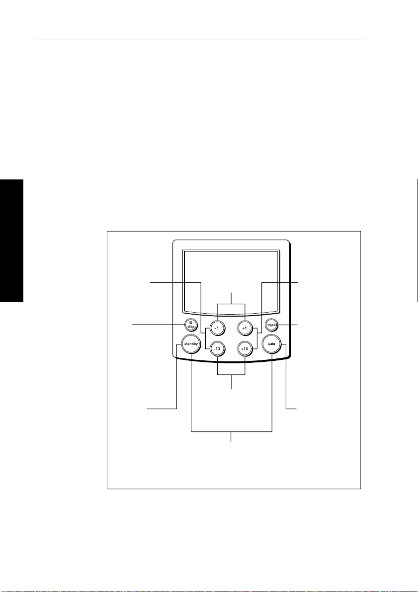
Keypad functions
The autopilot is controlled using si mple push-button operations, all of
which are confirmed with a short beep. In addition to the main
single-key functions, there are several dual key operations.
2 Basic Operation
-1 plus -10
Press together
for AutoTack
to port
standby at any time to return to manual
-1 plus +1
Press for Response level
Press for 1 second
for Rudder Gain
+1 plus +10
Press together
for AutoTack
to starboard
DISP
Press to display
data pages
Press for 1 second
for lamp control
STANDBY
Press for
Standby mode
Press for 2 seconds
to enter Calibration mode
Course change keys
Port 1˚ Starboard 1˚
Port 10˚ Starboard 10˚
STANDBY plus AUTO
Press for Wind Vane mode
(if a wind vane is connected)
Press for 1 second for Last Wind
Press again to accept Last Wind
TRACK
Press for Track
mode from Auto
(if a navigator is
connected)
Press to accept
waypoint advance
Press for 1 second
to skip waypoint
AUTO
Press for Auto mode
Press for 1 second
for Last Heading
Press again to
accept Last Heading
D5449-1
Page 18
Chapter 2: Basic Operation 5
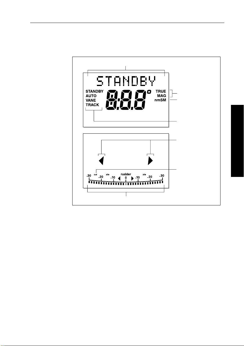
Display layout
The ST6001+ display screen provides the following informati on:
Variable text region (up to 9 characters/digits)
Heading indicators
Distance units:
• no units = kilometres
• nm = nautical miles
• SM = statute miles
Autopilot mode
indicators
Port and Starboard
direction-to-steer
indicators
Calibration mode
indicator (displayed on
calibration pages)
2 Basic Operation
Rudder position indicator or error bar
D5457-1
The bar graph at the bottom of the screen is normally a rudder position
indicator. This indicates the current position of the rudder , as
measured by the rudder position sensor .
Note: You can change this to a headi ng/cross track/wind error bar in
Display Calibration, seepage 79.
Page 19
6 ST6001+ Autopilot Control Unit - Owner’s Handbook
2.2 Using Auto mode
CAUTION:
Before using Auto mode, make sure that the pilot has been
correctly commissioned.
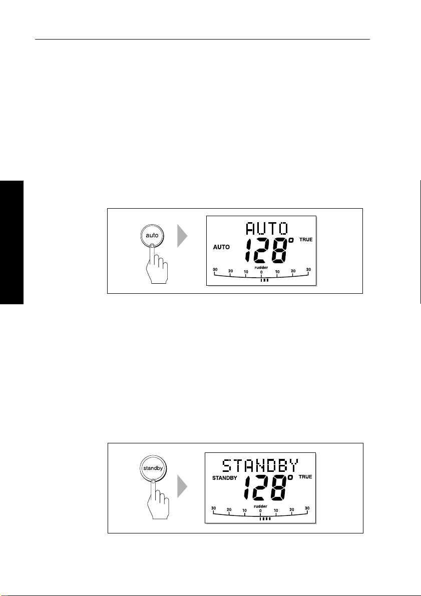
Engaging the autopilot (Auto mode)
T o engage the autopilot:
1. Steady the boat on the required heading.
2. Press
2 Basic Operation
CAUTION:
Autopilot course control makes it easier to sail a boat, but it is
NOT a substitute for good seamanship. ALW A YS maintai n a
permanent watch by the helm.
auto:
• in Auto mode, the display shows the locked autopilot heading
D3560-3
Disengaging the autopilot (Standby mode)
Press standby to disengage the autopilot:
• in Standby mode, the display shows t he boat’s current compass
heading.
• the last heading is memorized and can be recalled (see page 11).
D3561-3
Page 20
Chapter 2: Basic Operation 7
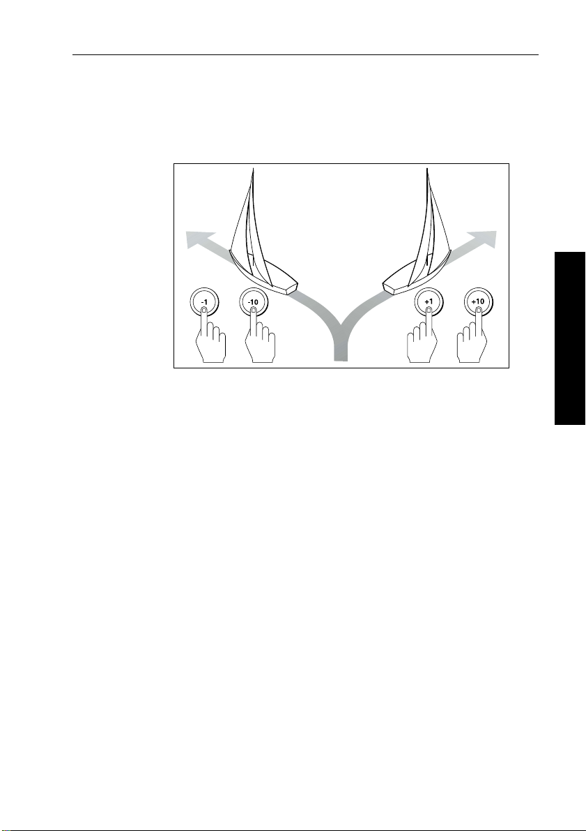
Changing course in Auto mode
In Auto mode, use the -1 and -10 (port) and +1 and +10 (starboard )
keys to change the locked heading in steps of 1° or 10°. For example:
press
-10 three times for a 30° co urse change to port.
Port Starboard
Adjusting performance – Type 150G/400G
The main way you can adjust the performance of T ype 150G/400G
(GyroPlus) autopilot systems is by changing the response level. Thi s
is the only user adjustment you should need to make to t he autopilot
on a regular basis.
The response level controls the relationship between the autopilot’s
course keeping accuracy and the amount of helm/drive activity.
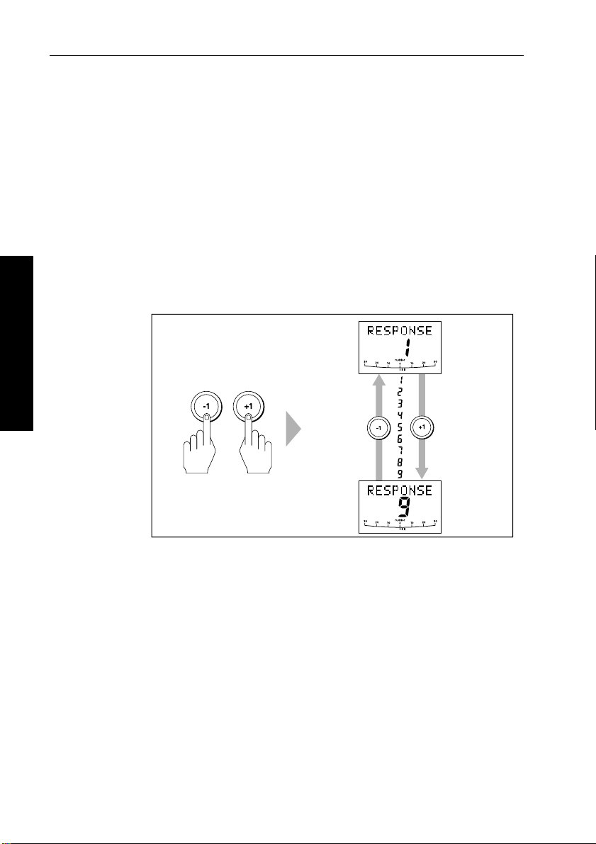
T ype 150G and 400G autopilot systems have 9 l evels of response:
• level 1 gives the least pilot activity to conserve power, but may
compromise short-term course-keeping accuracy
• levels 4 to 6 should give good course keeping under nor mal
operating conditions – with crisp, well controlled turns but
without being over-aggressi ve
• level 9 gives the tightest course keeping and gr eatest rudder
activity , but may lead to a rough passage in open waters as the
autopilot may ‘fight’ the sea
oror
2 Basic Operation
D3320-2
When you require extra tight course keeping (e.g. for pilotage in
confined and sheltered waters), increase the setting. If you want t o
minimize drive activity and conserve battery power , decrease
the setting.
Page 21
8 ST6001+ Autopilot Control Unit - Owner’s Handbook
Y ou ca n adjust the default response level in either User or Dealer
Calibration (see page 85). This determines the default power-up
response level.
However, when using your aut opilot on a day-to-day basis, you can
make temporary adjus tments to the response level. By doing this
you can match autopilot performance to different conditio ns.
Temporary changes to response – Type 150G/400G
With these points in mind, you should use the following procedure to
make temporary adjustments to the response level when required:
1. Display the
together momentarily .
2 Basic Operation
RESPONSE screen by pressing the -1 and +1 keys
Decrease
response
Increase
response
D5452-1
Note: The RESPONSE screen is set as a default data page (see
page 81) so you can also access it by pressing
disp and then scrolling
through the data pages.
2. Press
3. Press
-1 or +1 to change the response level.
disp or wait for 5 seconds to return to the previous display .
Note: Y ou will lose these temporary changes to response level
whenever the system is powered off. You can make permanent
adjustments in User or Dealer Cali bration (see page 85).
Adjusting performance – Types 150/400 and 100/300
T o adjust the performance of T ype 150/400 (non-GyroPlus) and
T ype 100/300 autopilot systems you can change the respon se level.
Page 22

Chapter 2: Basic Operation 9
Response level – Types 150/400 and 100/300
The response level controls the relationship between the autopilot’s
course keeping accuracy and the amount of helm/drive activity.
Y ou can adjust the default response level in either User or Dealer
Calibration (see page 85). This determines the default power-up
response level.
However, when usi ng your autopilot on a day-to-day basis, you will
need to make temporary adjustments to the response level. By doing
this you can match autopilot performance to different conditi ons.
T ype 150/400 (without GyroPlus ) and T ype 100/300 autopilot
systems have three different response levels:
• Response Level 1: AutoSeastate on ( Automatic deadband )
This setting causes the autopilot to gradually ignore repetitive
boat movements and only react to true variations in course. This
provides the best compromise between power consumptio n and
course keeping accuracy, and is the default calibration setting.
• Response Level 2: AutoSeastate off (Minimum deadband)
This setting provides tighter course keeping. How ever, this
results in increased power consumption and drive unit activity .
• Response Level 3: AutoSeastate off + yaw damping
This setting provides the tightes t possible course keeping by
introducing counter rudder yaw damping. You can adjust the
counter rudder setting in Dealer Calibration (see page 91)
2 Basic Operation
To make a temporary change to the response setting:
1. Display the
together momentarily .
2. Press
3. Press
Note: Y ou will lose these temporary changes to response level
whenever the system is powered off. You can make permanent
adjustments in User or Dealer Calibr ation (see page 85).
RESPONSE screen by pressing the -1 and +1 keys
-1 or +1 to change the response between levels 1 to 3.
disp or wait for 5 seconds to return to the pr evious display .
Page 23
10 ST6001+ Autopilot Control Unit - Owner’s Handbook
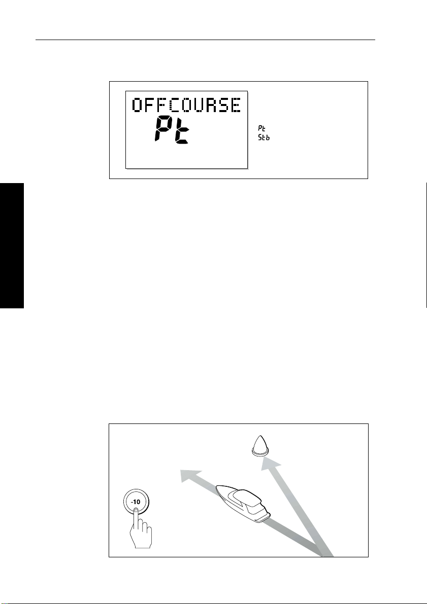
Off Course warning
= deviation to port
= deviation to starboard
D3315-2
The ST6001+ activates the OFF COURSE warning when the boat has
been off course from the locked heading by more than the specified
angle* for longer than 20seconds. It shows whether the deviation is to
port or starboard.
Note: * Y ou can adjust this specified off course angle i n Dealer
Calibration (see page 93).
2 Basic Operation
1. T o cancel the off course warning, press
steering.
standby t o return to hand
2. Check whether your boat is carrying too much sail, or whether the
sails are badly balanced. Y ou can usually signif icantly improve
course keeping by improving the sail balance.
Note: T he ST6001+ also clears the warning if the heading r ecovers,
if you change the course, or if you change the operating mode.
Dodging obstacles and then resuming course
T o avoid an obstacle when your boat is under autopilot contr ol, you
can dodge the obstacle and then resume your previous course.
Dodging an obstacle
Obstacle
Original
course
Dodge
D3303-2P
Page 24
Chapter 2: Basic Operation 11
Dodging an obstacle
1. Select a course change in the appropriate direction. For example,
press
-10 three times for a 30° dodge to port.
2. When safely clear of the obstacle, you can either:
• reverse the previous course change (for example, press
+10
three times), or
• return to the previous locked heading (
LAST HDG) as described
below
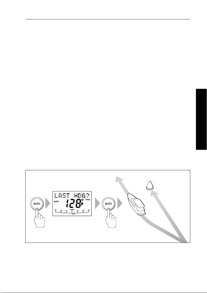
Returning to the previous heading (LAST HDG?)
When the boat is in Auto mode and you have steered the boat away
from the selected locked heading for any reason (for example, to
execute a dodge maneuver), you can return to the prev ious locke d
heading (the most recent heading held for 20 seconds). To do this:
2 Basic Operation
1. Press
2. T o accept this heading, and resume this course, press
Note: If you do not press
autopilot will maintain the current heading.
Returning to last heading
1 SECOND
auto for 1 second. The display flashes and shows t he
previous locked heading (
LAST HDG?) for 10 seconds. The
direction-to-steer indicator shows the direction the boat will turn.
auto when
the display is flashing.
auto while the display is flashing, the
Resumed
course
Obstacle
Original
course
Dodge
D5499-1
Page 25
12 ST6001+ Autopilot Control Unit - Owner’s Handbook
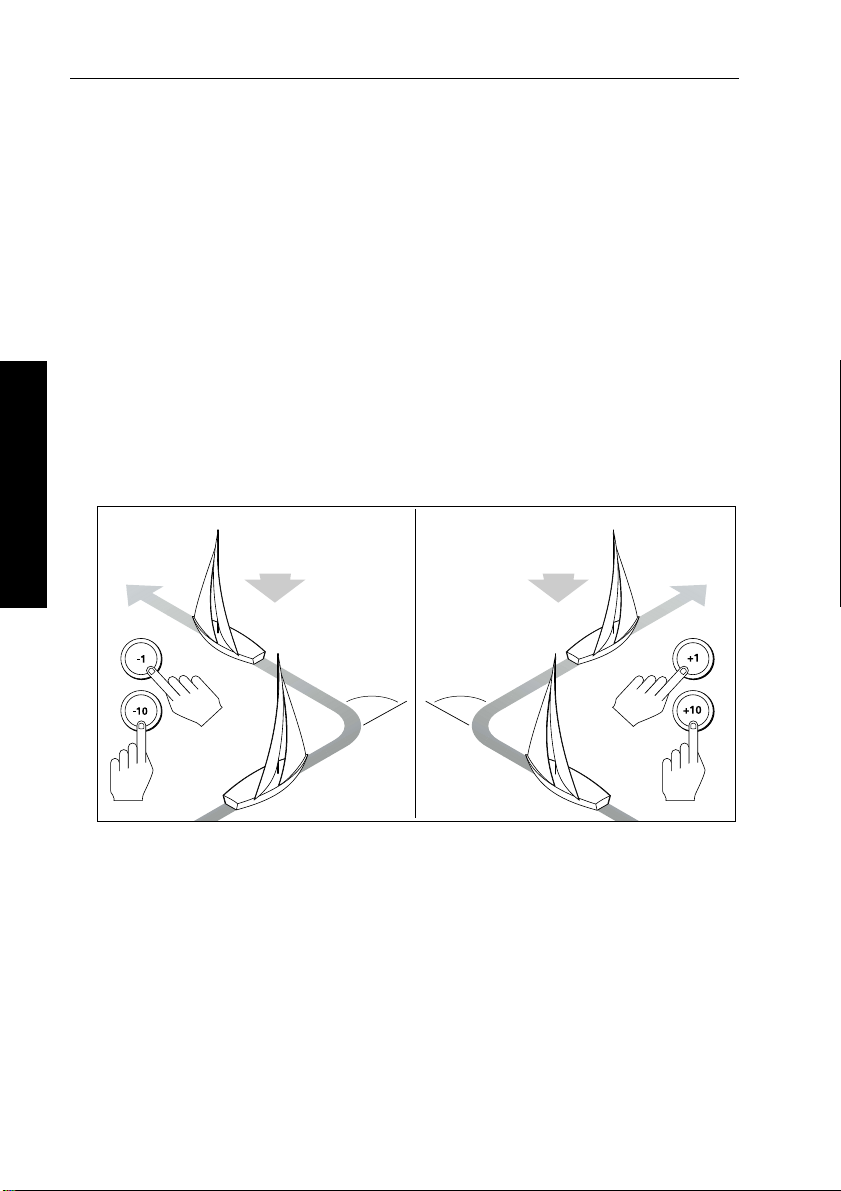
Using sail boat features
Automatic tack (AutoTack)
The ST6001+ has a built in automatic tack facility (AutoT ack) that
turns the boat through 100° in the required direction. If you have s et
the vessel type to
angle in User or Dealer calibration (see page 83).
SAIL BOAT, you can adjust the default AutoTack
• to AutoTack to port: press the
• to AutoTack to starboard: press the
-1 and -10 keys together
+1 and +10 keys together
CAUTION:
When making major course changes, the trim on the boat may
change substantially. Becau se of this, the autopilot may take
some time to settle accurately onto the new course.
AutoTack - Port
AutoTack - Starboard
2 Basic Operation
Wind
AutoTack
angle
AutoTack
angle
Wind
D5399-1
Preventing accidental gybes
Note: For the gybe inhibit feature to work, the autopilot needs
suitable wind information (see page23).
The gybe inhibit feature stops the boat from performing an AutoT ack
away from the wind – this will prevent accidental gybes. On T ype
150/150G and 400/400G autopilots, you can turn of f this feature if
required:
Page 26

Chapter 2: Basic Operation 13
• with gybe inhibit on:
• you will be able to perform an AutoTack into the wind
• to prevent accidental gybes, the autopilot will prevent the bo at
from performing an AutoT ack away from the wind
• with gybe inhibit off:
• you can perform an AutoT ack into or away from the wind.
Note: Gy be inhibit is switched on as a default. On T ype 150/150G
and Type 400/400G autopilots you can swit ch it off in User or Dealer
Calibration (see page 83).
Gusty conditions
In gusty conditions, the course may tend to wander sl ightly ,
particularly if the sails are badly balanced. If you take the following
precautions, the autopilot will be able to maintain competent control
even in gale force conditions:
• Y ou can significantl y improve course keeping by improving the
sail balance:
• do not allow the boat to heel over excessively
• ease the mainsheet traveller to leeward to reduce heeling and
weather helm
• if necessary, reef the mainsail a little early
• In very strong winds and lar ge seas, you should avoid sailing with
the wind dead astern:
• ideally, bring the wind at least 30° away from a dead run
• in severe conditions, you may also need to remove the
mainsail and sail under headsail only
2 Basic Operation
Page 27
14 ST6001+ Autopilot Control Unit - Owner’s Handbook
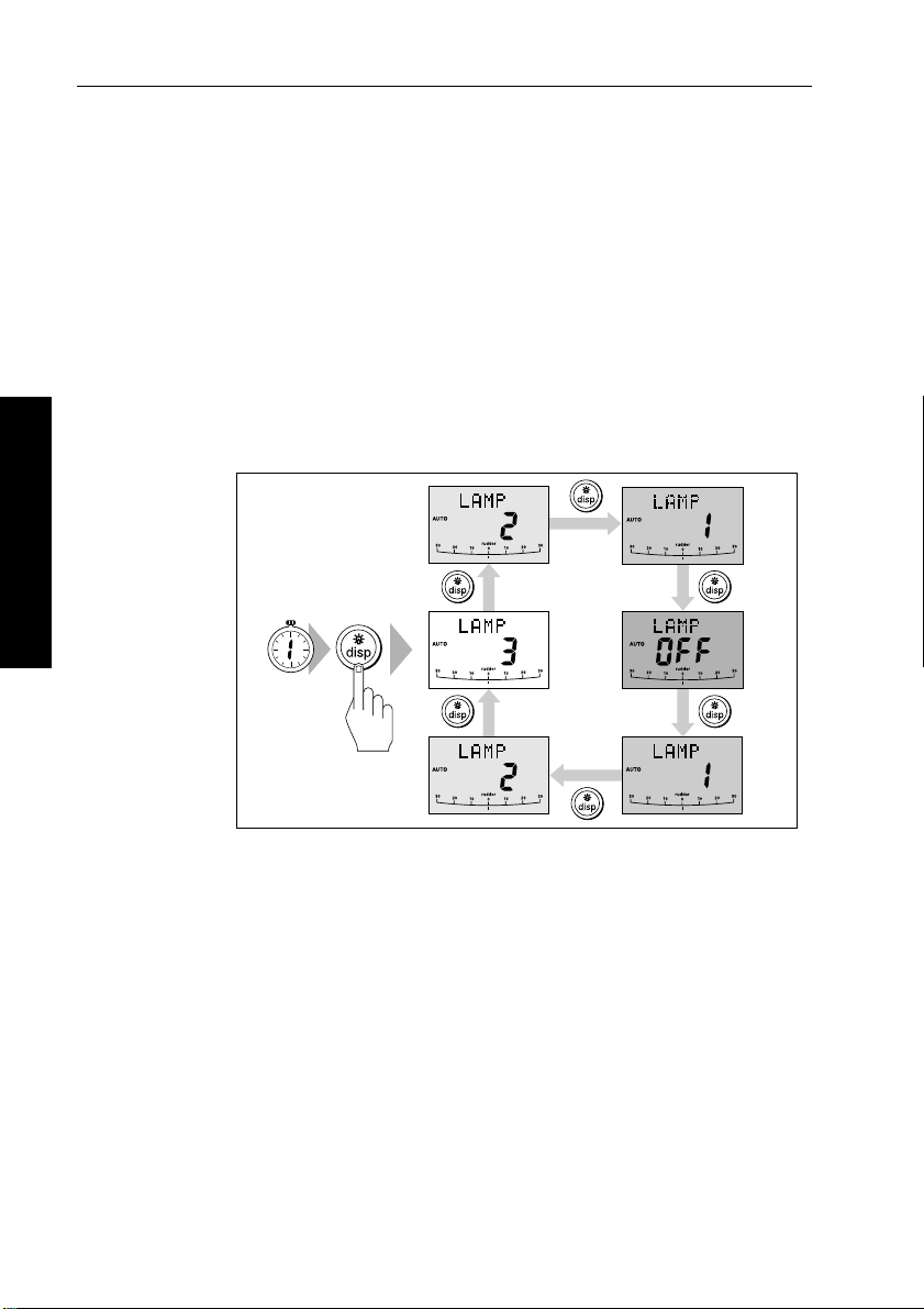
2.3 Adjusting display/keypad lighting
Note: When the display lighting is off, the control unit illuminates the
keys at a courtesy level.
T o adjust the display and keypad lighting:
1. Press
2. Press the
.
2 Basic Operation
disp for 1 second from any mode to access the LAMP screen
and turn on the lights.
disp key to cycle through the poss ible illumination
settings:
LAMP 1, LAMP 2, LAMP 3
LAMP 3 (the brightest setting), LAMP 2, LAMP 1, OFF,
and so on:
• as you change the setting, the illumination on any other
SeaTalk instruments or con trol units will also change
SECOND
D3313-3
3. The display automatically returns to the previous mode if you do
not press a key for 10 seconds:
• if you press another mode key within 10 seconds you wil l
select the mode assigned to that key (for example:
auto
selects Auto mode, standby selects Standby mode)
Note: You can als o adjust the lighting level from any other SeaTalk
instrument or control unit .
Note: W hen you switch off the unit you lose any changes you have
made to the lighting level.
Page 28
Chapter 3: Advanced Operation 15
Chapter 3: Advanced Operation
The sections in this chapter explain how to use the more advanced
functions on your autopilot:
Using Track mode
3.1
3.2
3.3
3.4
Tracking between waypoints created on navigation
equipment connected to the autopilot system.
Using Wind Vane mode – sail boats
Using the autopilot to maintain a course relative to a
true or apparent wind angle.
Adjusting the rudder gain
Explains how to adjust the rudder gain setting (mainly
applies to non-GyroPlus Type 150/400 systems).
Displaying data pages
Describes how to use d ata pages to display SeaTalk and
NMEA information on the cont rol unit. This section also
explains the Watch timer feature.
page 16
page 23
page 27
page 29
Note: If you are using the control unit with a non-150/40 0 autopilot
system, re fer to the no tes in the A ppendix.
3 Advanced Operation
Page 29

16 ST6001+ Autopilot Control Unit - Owner’s Handbook
3.1 Using Track mode
Note: Y ou can only use Track mode if you have connected the
autopilot to a suitable navigation sys tem providing SeaTalk or
NMEA navigation information.
The autopilot system can receive track information from either:
• a SeaTalk navigation ins trument or chartplotter (see page 49 for
information on connecting to SeaT alk), or
• a non-SeaT alk navigation system transmitting dat a in the
NMEA 0183 format (see page 50 for information on connecting
NMEA equipment)
In Track mode, the autopilot maintains a t rack between waypoints
created on the navigation system. The autopilot makes any course
changes necessary to keep your boat on track, automatically
compensating for tidal streams and leeway.
Selecting Track mode
CAUTION:
When you enter T rack mode, the autopilot will bring the boat
onto the track in a controlled way. The closer the boat is to the
correct heading and track, the quicker the autopilot will settle the
boat onto the new course. T o avoid a n unexpected turn,
approximately ali gn the boat with the requir ed track before
entering Track mode.
3 Advanced Operation
T o select Track mode:
1. Star t with the a utopilot in Auto mo de.
2. Press
3. W ait for the W aypoint Advance warning t o sound. The display
4. Check that it is safe for the boat to turn onto the new course.
5. Press the
track to enter Track mode.
will show the bearing to the next planned waypoint and the
direction the boat will turn to reach this waypoint.
track key :
• the autopilot will turn the boat onto the new course in a
controlled way
• the display shows the heading required to achieve the
required track
Page 30
Chapter 3: Advanced Operation 17
Note: T he closer the boat is to the correct heading and track when
you press
track, the quicker the autopilot will bring the boat onto the
new course. If the boat is more than 0.3 nm from the track, the Large
Cross Track Error warning will so und (see page 17).
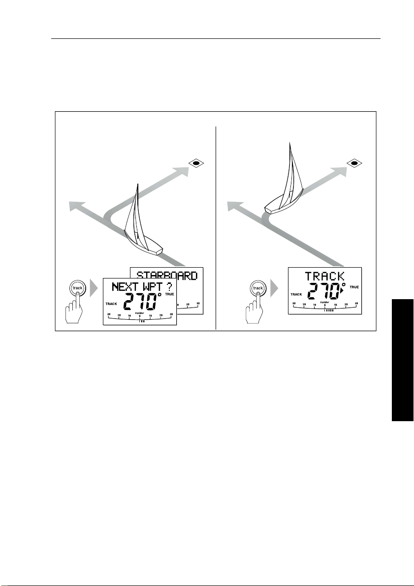
Automatic track acquisition
From auto mode, press track to enter Track mode: Then press track again to turn boat to waypoint:
Waypoint
at 270˚
Waypoint
at 270˚
Current
heading
Exiting Track mode
Y ou can exit T rack mode and return to Auto or Standby mode by :
• pressing
• pressing
Cross track error
Cross track error (XTE) is the distance between the current position
and a planned route. The autopilot receives the cross track error
information from the navigation equipment, and displays the XTE in
nautical miles (
Previous
heading
auto to return t o Auto mode
standby to steer manually in Standby mode
nm), statute miles (SM) or kilometres.
D5414-1
3 Advanced Operation
If the cross track error is greater than 0.3 nm, the ST6001+ will sound
the Large Cross Track Error warning and show whether you are to the
port
(Pt) or starboard (Stb) of the planned track.
Page 31

18 ST6001+ Autopilot Control Unit - Owner’s Handbook
Cross track error (XTE)
more than 0.3 nm
Actual route
Planned route
Waypoint 2
3 Advanced Operation
Waypoint 1
Tidal stream compensation
Under most conditions, the autopilot will hold the selected track to
within ±0.05 nm (300 ft) or better. The autopilot takes account o f the
boat’s speed when computing course changes to ensure optimum
performance over a wide range of boat speeds.
Boat's speed over ground
D5415-1
Waypoint 2
Tidal component
Boat's speed through water
Waypoint 1
D3261-2
Page 32

Chapter 3: Advanced Operation 19
In order of preference, the autopilot uses:
• measured boat speed (speed through water)
• if this is not available, it uses the speed over ground (SOG)
• if this is not available, it uses the cruise speed specified in Dealer
Calibration (see page 95)
Waypoint arrival and advance
Note: W aypoint advance only operates if the ST6001+ is receiving
valid bearing to waypoint and waypoint nam e information.
Arrival
As the boat arrives at the target waypoint the navigation aid will select
the next target waypoint and transmit this to the autopilot. The
autopilot will then detect the new target waypoint name, sound the
W aypoint Advance warning and display the W a ypoint Advance
(
NEXT WPT) screen. This shows the new bearing to the next waypoint
and the direction the boat will turn to acquire the new track.
Waypoint arrival and advance
Waypoint arrival Waypoint advance
Next target
waypoint at 270˚
New target
waypoint at 270˚
3 Advanced Operation
Target
waypoint
Old target
waypoint
D5416-1
Page 33

20 ST6001+ Autopilot Control Unit - Owner’s Handbook
Advance
When the ST6001+ sounds the W a ypoint Advance warning, it
suspends Track mode and maintains t he current boat heading.T o
advance to the next waypoint:
1. Check that it is safe to turn onto the new track.
2. Press the
warning and turn the boat towards the next waypoint.
track key . This wi ll cancel the W aypoint Advance
3 Advanced Operation
Note: If you do not press
autopilot will maintain the current headi ng and continue sounding
the warning.
track to accept the Waypoint Advance, the
Skipping a waypoint – SeaTalk navigators only
If you want to advance to the next waypoint before you have arrived
at the target waypoint, you can skip a waypoi nt by pressing
1 second. The display will then show the W aypoint Advance screen
for the ne xt waypoint. C heck it is saf e to turn, the n press
the boat towards the next waypoint.
WARNING:
Skipping a waypoint will take you stra ight to the next waypoint.
Check your navigation before maki ng the turn.
Route Completed warning
The ST6001+ displays the ROUTE COMPLETED warning when you
have reached the last waypoint on a route in Track mode.
T o respond to this message:
• press
• or press
auto to conti nue on the same heading
standby to return to hand steering
Waypoint Advance warning – summary
track for
track to turn
The ST6001+ activates the W aypoint Advance warning (NEXT WPT?)
in Track mode whenever the target waypoint name changes. This
occurs when:
• you select automatic acquisition by pressing
• you request waypoint advance by pressing
Track mode (with SeaT alk navigators onl y)
track from Auto
track for 1 second in
Page 34

Chapter 3: Advanced Operation 21
• the boat arrives at the target waypoint and the navigator accepts
the next waypoint
• you activate the Man Overboard (MOB) function in Track mode
When the warning sounds, the pilot continues on its current heading
but displays:
• the bearing to the next waypoint
• the direction the boat will turn to take up that bearing
Responding to a Waypoint Advance warning
T o respond to a W aypoint Advance warning:
• check that it is safe to turn onto the new track, then press
accept the waypoint advance
• alternatively, yo u can cancel the warning without accepting the
waypoint advance by pressing:
standby to ret urn to hand steering
•
• or
auto to return to Auto mode
Dodges in Track mode
When the autopilot is in Track mode you still have full control from
the keypad.
Initiating a dodge maneuver
In Track mode, you can make a dodge maneuver by u sing the course
change keys (
Cancelling a dodge maneuver
After you have avoided the hazard, you can cancel the dodge course
change by making an equal course change in the opposite direction.
-1, +1, -10 or +10) to select the desired course change.
track to
3 Advanced Operation
Page 35

22 ST6001+ Autopilot Control Unit - Owner’s Handbook
Safety in Track mode
CAUTION:
T rack mode provides accurate track keeping even in complex
navigational situations. However, it is still the skipper’s
responsibility to ensur e the safety of their boat at all times
through careful navigation and frequent position checks.
Sailing in Track mode assists preci se navigation and removes the
tasks of compensating for wind and tidal dri ft. However, you MUST
still maintain an accurate log with regular plots.
Confirming position at the start of a journey
At the start of a journey you must always use an easily identifiable
fixed object to confirm the fix given by the navigation system. Check
for fixed positional errors and compensate for them.
Verifying computed positions
Always verify the computed position with a dead reckoned positio n,
calculated from the average course steered and the distance logged.
3 Advanced Operation
Plot frequency
• In open water, you sh ould make plots at least every hour .
• In confined waters or when near to potential hazards, you should
make plots more frequently .
Page 36

Chapter 3: Advanced Operation 23
3.2 Using Wind Vane mode – sail boats
Note: Y ou can only select Wind Vane mode if the autopilot i s
receiving suitable SeaTalk or NMEA wind direct ion information.
About Wind Vane mode
When the autopilot is in Wind V ane mode it uses the fluxgate
compass as the primary heading reference. As changes in the true or
apparent wind angle occur, the autopilot adjusts the locked compass
heading to maintain the orig inal wind a ngle.
Wind information
T o use Wind V ane mode, the autopilot must receive wind information
from one of the following sources:
• SeaTalk wind instrument connected to the autopilot via SeaT alk
• NMEA wind instrument
• Raymarine pushpit wind vane connected via a SeaTalk interface
True and apparent wind
T ype 150/150G and 400/400G autopilots can mainta in a course
relative to either an apparent or true wind angle in W ind V ane mode:
• steering to apparent w ind, the autopilot maintains the apparent
wind angle
• steering to true wind, the autopilot maintains the true wind angle
Note: T he default setting is apparent wind. On T y pe 150/150G and
400/400G autopilots you can change thi s to true wind in User or
Dealer Calibration (see page 85). Type 100/300 autopilots can only
maintain a course relative to apparent wind.
3 Advanced Operation
WindTrim
In Wind Vane mode the autopilot uses Wi ndTrim to eliminate the
effects of turbulence and short term wind variations. This pr ovides
smooth and precise performance with minimal power consumpti on.
Y ou can adjust the wind response (WindT rim) level in User or Dealer
Calibration (see page 85) to control how quickly the autopilot
responds to changes in the wind direction. Higher wind trim settings
will result in a pilot that is more responsive to wind changes.
Page 37

24 ST6001+ Autopilot Control Unit - Owner’s Handbook
Selecting Wind Vane mode
Y ou can select W ind V ane mo de from either Standby or Auto mode:
1. Steady the boat onto the required wind angle.
2. Press
standby and auto together to select Wind V ane mode and
lock the current wind angle:
• the display shows the locked heading (e.g.
angle (e.g.
WIND 145P indicates an wind angle of 145° to port)
128°) and the wind
• if the autopilot does not enter Wind V ane mode, it is not
receiving wind data - check the instrument and connections
D3565-3
The autopilot will then adjust the boat’s heading to maintain the
locked wind angle.
Exiting Wind Vane mode
3 Advanced Operation
Y ou can exit W ind V a ne mode by:
• pressing
• pressing
auto to ret urn to Auto mode
standby to steer manually in S tandby mode
Adjusting the locked wind angle
Y ou can adjust the locked wind angle by using the -1, +1, -10 and +10
keys to change course. For example, to bear away by 10° when th e
boat is o n a star board ta ck:
• press
• the autopilot will then adjust the locked heading as required to
Note: Becaus e turning the boat affects the relationship between the
true and apparent wind angles, you shoul d only use this method to
make minor adj ustments to the wind angle. For major changes,
return to Standby mode, steer onto the new heading, then re select
Wind Vane mode.
-10 to turn the boat 10° to port – the locked wind angle and
locked heading will both change by 10°
maintain the new wind angle
Page 38

Chapter 3: Advanced Operation 25
Returning to the previous wind angle (LAST WND)
If you have steered the boat away from the selected wind angle for
any reason (such as a dodge maneuver or selecting Standby mod e),
you can return to the previous locked wind angle:
1. Press
2. Check that it is safe to turn onto this course.
3. To accept this wind angle, press
standby and auto together for 1 second to display the
previous wind angle (
• the
LAST WND?text alternates with the previous wind angle
LAST WND?):
and direction. The display shows the previous locked heading
and an indication of which direction the boat will turn
SECOND
standby and auto together
within 10 se conds.
D3566-3
3 Advanced Operation
Note: If you do not accept the previous wind angle within 10 seconds,
the autopilot will lock onto the current wind angle.
Dodges in Wind Vane mode
When the autopilot is in Wi nd V ane mode you s till have full control
from the keypad.
Initiating a dodge maneuver
In Wind Vane mode, you can make a dodge maneuver by using the
course change keys (
change. The autopilot will adjust both the locked heading and locked
wind angle.
Cancelling a dodge maneuver
After you have avoided the hazard, you can reverse the previous
course change, or return to the previous wind angle (
-1, +1, -10 or +10) to select the desired course
LAST WND?).
Page 39

26 ST6001+ Autopilot Control Unit - Owner’s Handbook
Wind Shift warning
If the autopilot detects a wind shift of more than 15° it will sound the
wind shift warning and display the
WIND SHIFT message:
• T o cancel the warning, and retain the existing wind angle and new
heading, press
standby and auto together.
• Alternatively, to cancel the warning and return to the previous
heading, either:
• adjust the locked wind angle using the
-1, +1, -10 and
+10 keys,
or
• press
standby to return to hand steering, st eer onto the
required heading, and press
standby and auto together to
return to Wind Vane mode with the new wind angle
Using AutoTack in Wind Vane mode
Note: If you us e the AutoTack function in Wind Vane mode, make
sure the wind vane has been centered accurately.
The ST6001+has a built in automatic tack facility (AutoT ack) that
turns the boat through 100° in the required direction:
3 Advanced Operation
AutoTack - Port
• to AutoTack to port: press the
• to AutoTack to starboard: press the
Wind
AutoTack
angle
-1 and -10 keys together
+1 and +10 keys together
AutoTack - Starboard
Wind
AutoTack
angle
D5399-1
Note: If you ha ve set the vessel type to SAIL BOAT, you can adjust the
default AutoTack angle in User or Dealer calibrat ion (see page 83).
Page 40

Chapter 3: Advanced Operation 27
When you AutoT ack in Wind Vane mode, the boat turns through the
AutoTack angle. The autopilot will then trim the heading to mirror the
locked wind angle from the previous tack.
Operating hints for Wind Vane mode
• Always trim your sails carefully to minimize the amount of
standing helm.
• Reef the headsail and mainsail a little early rather than too late.
• In Wind Vane mode the pilot will react to long-term wind shifts,
but will not correct for short-term changes such as gust s.
• In gusty and unsteady inshore conditions, i t is best to sail a few
degrees further off the wind so that changes in wind direction can
be tolerated.
3.3 Adjusting the rudder gain
Note: Al though this feature is available on all systems, you should
not need to adjust the rudder gain s etting on Type 150G/400G
autopilot systems after completing the AutoLearn (see page 68).
Increase
rudder gain
D5400-1
SECOND
Decrease
rudder gain
On T ype 150/400 (non-GyroPlus) and T ype 10 0/300 systems, you
can make temporary adjustments to rudder gain to change the
autopilot’s steering characteristics. Rudder gain is a measure of how
much helm the autopilot will apply to correct course errors:
• if rudder g ain is adju sted correctly, the course changes should
result in a crisp turn followed by an overshoot of no more than 5°
3 Advanced Operation
Page 41

28 ST6001+ Autopilot Control Unit - Owner’s Handbook
• if rudder gain is too high, courses change will result in a distinct
overshoot (
A)
• if rudder gain is too low, the boat will feel sluggish – it wi ll take a
long time to make the turn and there will be no overshoot (
New
heading
Rudder gain
too low
Rudder gain
too high
B
rudder gain
Correct
New
heading
A
B)
New
heading
D3262-2
Note: See pag e 71 for a full explanation of rudder gain and how to
adjust it correctly.
If necessary , you can make a temporary change to rudder gain
as follows:
3 Advanced Operation
1. Press the
rudder gain (
• if you have set up the
-1 and +1 keys together for 1 second to display th e
RUDD GAIN) screen:
RUDD GAIN screen as a default data page
(see page 81) you can also access it by pressing
disp and then
scrolling through the data pages.
2. Press
3. Press
-1 or +1 to change the rudder gain.
disp or wait for 5 seconds to return to the previous display .
Note: Y ou will lose these temporary changes to rudder gain
whenever the system is powered off. You can make permanent
adjustments in User or Dealer Cali bration (see page 91).
WARNINGS:
1. Y ou must set rudder gain correctly on planing craft. Incorrect
rudder gain will lead to poor steering performance and can be
dangerous at hig h speeds.
2. If you increase the rudder gain setting on a T ype 150G/400G
autopilot, you must also increase the counter rudder setting.
Page 42

Chapter 3: Advanced Operation 29
3.4 Displaying data pages
Use the disp key to show ‘data pages’ of SeaT alk or NMEA data:
1. Press
2. Select the data page you want to use as the main display:
Notes: 1. If the aut opilot system cannot obtain the required
information, the data page will sh ow dashes instead of a value.
2. The direction-to-steer arro ws relate to the data page information.
3. Most data pages show repeated data so you cannot adjust them: the
exceptions are the
you can adjust using the
t
Default data pages
disp to access the first data page, and press it again to cycle
through each data page in turn:
• to return to a previous data page, press
disp for 1 second
within 2 seconds of displaying a page
• when you cycle past the last data page, the display returns to
the current autopilot mode screen (for example, Auto)
• 4 data pages are set in the factory as a default (see diagram):
within User setup you can select up to 7 pages and control the
information they display (see page 81)
• the current autopilot mode is shown at the left of the display
and the autopilot bar graph remains in use
• if you then select a new mode or make a course change, the
autopilot mode screen appears as a ‘pop-up’ for 5 seconds
RESPONSE and RUDDER GAIN data pages, which
-1 and +1 keys
3 Advanced Operation
Data page 4
Data page 3
Autopilot mode
Press for 1 sec to
return to previous
data page
Data page 1
Data page 2
D5455-1
Page 43

30 ST6001+ Autopilot Control Unit - Owner’s Handbook
Watch timer
The ST6001+ has a W atch timer controlled by the WATCH data page.
This timer sounds a warning every 4 minutes, requirin g a keypad
press on the autopilot.
Setting the Watch timer
T o set the Watch timer:
3 Advanced Operation
1. First, you must configure the
pages for display (see page 81).
2. When you have done this select Auto, T rack or Wind Vane mode.
3. Press the
• the watch timer will start counting
• when the timer reaches 3 minutes, the
• when the timer reaches 4 minutes, the ST6001+ activates the
Responding to a Watch warning
T o respond to a W atch warning:
• press
or
• press any other key to silence the warning, reset the timer and
perform that key’s normal function
Note: You cannot engage Auto mode directly when the
is displayed – pressing
want to ente r Auto mode, y ou must fi rst exit the
(see below).
Exiting the Watch screen
T o exit the Watch screen:
• press
or
• press
disp key until you see t he WATCH data page:
flashing to indicate that the timer is in the last minute
audible W atch warning
auto to silence the warning and reset the timer to 4 minutes
auto will o nly reset th e Watch tim er. If you
disp to display a different data page
standby
WATCH screen as one of the data
WATCH text starts
WATCH screen
WATCH screen
Page 44

Chapter 3: Advanced Operation 31
Warning messages
Shallow warning (SHALLOW)
The ST6001+ shows the Shallow warning if it receives a shallow
depth message from an instrument on the SeaT alk system. Press
standby or disp to cancel the warning.
Man Overboard warning (MOB)
The ST6001+ activates the Man Overboard warning if it receives a
man overboard (MOB) message from another instrument on the
SeaTalk system. It displays the text
number for the
XTE, DTW and BTW data pages.
MOB instead of the waypoint
3 Advanced Operation
Page 45

32 ST6001+ Autopilot Control Unit - Owner’s Handbook
3 Advanced Operation
Page 46

Chapter 4: Fault Finding & Maintenance 33
Chapter 4: Fault Finding & Maintenance
All Raymarine products are designed to provide many years of
trouble-free operation. W e also put them through comprehens ive
testing and quality assurance procedures before shipping.
This chapter provides information about identif ying common
problems, interpreting alarm messages, maintaining y our autopilot
system and obtaining product support.
If a fault occurs with your autopilot, use the fault finding t ables in this
section to help identify the problem and provide a solution.If you
cannot resolve the problem yourself, refer to the product support
information.
Fault finding
4.1
4.2
4.3
This section provides information to help you identify
and resolve common autopilot problems and error
messages.
General maintenance
This section explains how to maintain your autopilot
system.
Product support
This section outlines the product support available
from Raymarine worldwide.
page 34
page 37
page 38
4 Fault Finding & Maintenance
Page 47

34 ST6001+ Autopilot Control Unit - Owner’s Handbook
4.1 Fault finding
Common autopilot problems
SYMPTOM CAUSE and SOLUTION
Display is blank No power – check the power and SeaTalk fuses
on course computer, then check main
fuse/circuit breaker.
Display shows stationary dashes The control unit is not receiving data – check
Display shows rotating dashes Compass correction in progress (see page 64).
Displayed compass heading does
not agree with the boat’s compass
No display bar on the display Rudder bar switched off in Display Calibration
Rudder bar display moves in
opposite direction to rudder
Boat turns slowly and takes a long
time to come onto course
Boat overshoots when turning onto
a new course
The autopilot appears to be
unstable in Track mode, or
track-holding is slow
The autopilot appears to be
unstable on Northerly headings in
the Northern hemisphere (or
Southerly headings in the Southern
hemisphere)
You cannot enter Seatrial
Calibration
The autopilot will not ‘talk’ to other
SeaTalk instruments
Position information not received Navigator not transmi tting the correct position
The autopilot will not auto advance
to the next waypoint
4 Fault Finding & Maintenance
cabling.
You have not cali brated the compass. Carry out
the deviation and alignment procedures (see
page 64).
– select RUDD BAR or STEER BAR
Reverse the red and green rudder position
sensor connections at the course computer
Rudder gain too low (see page 71). Complete
AutoLearn or increase setting.
Rudder gain too high (see page 71). Complete
AutoLearn or decrease setting,
If tide speed exceeds 35% of boat speed, and
boat speed is not available via SeaTalk, change
the Cruise Speed setting in Dealer Calibration
to the boat’s cruising speed (see page 95).
Northerly/Southerly heading correction
(AutoAdapt) is not set up (see page 95). [Does
not apply to 150G/400G systems.]
Seatrial calibration lock is on – turn off the
calibration protection feature in Dealer
Calibration (see page 88).
Cabling problem – make sure all the cables are
connected properly.
data.
No bearing to waypoint information received
from the navigator.
Page 48

Chapter 4: Fault Finding & Maintenance 35
Autopilot alarm messages
When the autopilot detects a fault or failure on the system, it will
activate one of the alarm messages listed in the following table.
• Unless otherwise stated, you should respond to the alarm by
pressing
before you attempt to resolve the problem.
• In some situations, the autopilot will raise more than one alarm.
When you have dealt with the first alarm, the autopilot will
display the next alarm.
ALARM MESSAGE CAUSE and SOLUTION
AUTO RELEASE Possible fault with rudder position sensor – check connections.
CURRENT and LIMIT Serious drive failure – the drive is taking too much current due
DRIVESTOP The autopilot is unable to turn the rudder (this occurs if the
LOW BATT Supply voltage has dropped below acceptable limits.
LRN FAIL 1, 2 or 4 AutoLearn not completed successfully.
MOT POW and SWAPPED Motor cables are connected to power terminals (and power
[Table continues over page]
standby to clear the alarm and return to hand steering,
OR
Stern (I/O) drives only – you have taken manual control of
steering with AutoRelease on. The alarm cancels automatically
after 10 seconds.
to short-circuit or jamming. Check the drive unit.
weather load on helm is too high, or if the rudder position
sensor has passed beyond the preset rudder limits or rudder
end-stops).
Check drive and rudder position sensor.
To respond to a Low Battery alarm:
• press standby to clear the alarm and return to hand steering
• start the engine to recharge the battery
Failure codes:
1 = AutoLearn has not been carried out (default setting)
2 = AutoLearn failed, usually due to manual interruption
4 = AutoLearn failed, probably due to drive or compass failure
Repeat the AutoLearn procedure.
cables are connected to motor terminals) at course computer.
Turn off power and swap over connections.
4 Fault Finding & Maintenance
Page 49

36 ST6001+ Autopilot Control Unit - Owner’s Handbook
ALARM MESSAGE CAUSE and SOLUTION
NO DATA Ca use d by an y of the fol low ing sit uat ion s:
• the compass is not connected
• the autopilot is in Wind Vane mode and it has not received
wind angle data for 30 seconds
• the autopilot is in Track mode and:
• the autopilot is not receiving SeaTalk navigation data, or
• the position sensor (GPS, Loran, Decca) is receiving a low
strength signal – this will clear when the signal improves
Check the conne ctions to the compass and/or w ind instrument
and/or navigator.
Note: The autopilot stops adjusting the heading as soon as it
loses data.
NO PILOT The control unit is not re ceiving data from the course c omputer.
RG FAIL GyroPlus yaw sensor has failed:
SEATALK and FAIL 1 or 2 SeaTalk data problem on one of the SeaTalk lines – check
STLK FAIL The control unit cannot transmit data to the SeaTalk system.
Check connections and check co urse computer is switched on.
• If you have a Type 150G/40 0G course computer with internal
GyroPlus sensor – call a Raymarine service agent.
• If you ha ve a Type 1 50/40 0 co urs e co mpu ter with exter nal
GyroPlus yaw sensor – check the sensor and connections,
then call a Raymarine service agent.
connections.
Make sure all SeaTalk cables are connected properly.
4 Fault Finding & Maintenance
Page 50

Chapter 4: Fault Finding & Maintenance 37
4.2 General maintenance
Routine checks
CAUTION:
The control unit does not contain any user serviceable parts.
It should be serviced only by authorized Raymarine servi ce
technicians.
The control unit is a sealed unit. As a result, user maintenance is
limited to the following checks:
• make sure all cable connectors are firmly attached
• examine the cables for signs of wear or damage – replace any
damaged cables
Cleaning the display
CAUTION:
T ake care when cleaning the display. A void wiping the display
screen with a dry cloth as this could scratch the screen coating.
If necessary, only use a mild detergent.
• Never use chemical or abrasive materials to clean the control unit.
If it is dirty, wipe it with a clean, damp cloth.
• In certain conditions, condensation may appear inside the display
screen. This will not harm the unit, and you can clear it by
switching on the illumination for a short time.
EMC advice
• When powered up, all electrical equipment produces
electromagnetic fields. These can cause adjacent pieces of
electrical equipment to interact with one another, with a
consequent adverse effect on operation.
• T o minimize these effects and enable you to get the best poss ible
performance from your Raymarine equipment, guidelines are
given in the installation instructions, to enable you to ensure
minimum interaction between different items of equipment, i.e.
ensure optimum Electromagnetic Compatibility (EMC).
4 Fault Finding & Maintenance
Page 51

38 ST6001+ Autopilot Control Unit - Owner’s Handbook
• Always report any EMC-related problems to your ne arest
Raymarine dealer. We use such information to improve our
quality standards.
• In some installations, it may not be possible to preven t the
equipment from being affected by ext ernal influences. In general
this will not damage the equipment but it can lead to spurious
resetting action, or momentarily may result in faulty operation.
4.3 Product support
Raymarine products are supported by a worldwide network of
distributors and Authorized Service Representa tives. If you
encounter any difficulties with thi s product, please contact either
your national distributor , service representative, or the Raymarine
T echnical Services Call Center. Refer to the back cover or the
W orldwide Distributor List for contact details.
Before you consider returning the autopilot, make sure that the power
supply cable is sound and that all connections are tight and free fr om
corrosion. If the connections are secure, refer to the Fault Finding
section in this chapter (see page 34).
If you cannot trace or rectify the fault, contact your nearest
Raymarine dealer or Service Center, specifying:
• the control unit and course computer serial numbers:
• the control unit serial number is printed on its rear cover
• the course computer serial number is printed under its
connector cover
• the control unit and course computer software version numbers
The following illustration shows how to display the software
information:
• press and hold
• after 2 seconds you will see the
• then after another 2 seconds you see control unit software
version
• press
• press
4 Fault Finding & Maintenance
disp to display the course computer software version
disp again to display the total number of hours the autopilot
has been used in Auto mode (Note: T ype 100/300 systems do not
display hours used.)
standby for 4 seconds:
DISPLAY CAL screen
Page 52

Chapter 4: Fault Finding & Maintenance 39
Software information
4 seconds
Control unit
software version
1 second1 second
1 second
Course computer
software version
D5493-1
Time autopilot
used in Auto
Product details table
For future reference, you may want to use this table to record serial
and software information for your autopilot sys tem:
Serial number Software version
Control unit
Course computer
Hours used hours
4 Fault Finding & Maintenance
Page 53

40 ST6001+ Autopilot Control Unit - Owner’s Handbook
4 Fault Finding & Maintenance
Page 54

Part 2: Installing the ST6001+
Part 2: Installing the ST6001+
Page 55

Part 2: Installing the ST6001+
Page 56

Chapter 5: Installing the ST6001+ 43
Chapter 5: Installing the ST6001+
The sections in this chapter explain how to install the ST6001+
control unit and connect it to an autopilot system:
Select the location
5.1
5.2
5.3
5.4
5.5
Tools required
T o install the ST6001+ control unit you will need the following items:
How to select a suitable location for the ST6001+
control unit.
Control unit installation
How to install the ST6001+ control unit (surface mount
and flush mount options).
SeaTalk connections
How to connect the control unit to SeaTalk (for power
supply and SeaTalk data exchange).
NMEA connections
How to connect NMEA equipment to the control unit.
Functional test – repeater units only
How to check an ST60 01+ connected as a repeater unit
on an existing autopilot system.
5 Installing the ST6001+
page 44
page 47
page 49
page 50
page 53
• tape measure (metric/imperial)
• pencil and center punch
• pliers
• sandpaper/file to smooth cut edges
• additional SeaT alk cables (if required – see page 50)
• jigsaw or 90 mm hole cutter (for the control unit aperture)
5
• drill and 5 mm (
/32 in) drill bit
Parts supplied
• control unit and sun cover
• fixing studs (x2) and thumb nuts (x2)
• self-adhesive gasket
• 9 m (29 ft 6 in) SeaT alk cable
Page 57

44 ST6001+ Autopilot Control Unit - Owner’s Handbook
5.1 Select the location
Control unit dimensions
5 Installing the ST6001+
90 mm (3.55 in)
115 mm (4.53 in)
110 mm (4.33 in)
Site requirements
Locate the ST6001+ control unit so it is:
• within easy reach from the steering position
• viewable straight on, or with a maximum viewing angle of 30°
• protected from physical damage
• at least 230 mm (9 in) from any compass
• at least 1 m (3 ft) from any radio or radar receivers or transmitters
The selected location should also:
• be clean, smooth and flat
• be accessible from behind (so you can secure and run cables)
• have sufficient space to accommodate the rear of the control unit
and connectors
• allow at least 6 mm (
units/instruments so you can fit t heir sun covers
• meet the cabling and EMC installation guidelines detailed below
CAUTION:
The ST6001+ front cover is waterproof when instal led according
to the following instructions. However , you must protect the rear
of the control unit from water in a ventilated and drained area .
24 mm
(0.95 in)
1
/4in) between adjacent control
(0.67 in)
17 mm
D3242-2
Page 58

Chapter 5: Installing the ST6001+ 45
Any moisture or water vapor in this area could cau se damage by
coming into contact with electrical connections, or condensation
by entering the control unit through its breathing hole.
Cabling guidelines
• consider how you will run cables to and from the control unit
• avoid running cables through bilges where p ossible
• avoid running cables close to fluorescent lights, engi nes, radio
transmitting equipment etc.
EMC installation guidelines
All Raymarine equipment and accessories are designed to the best
industry standards for use in the recreational marine environment.
Their design and manufacture conforms to the appropriate
Electromagnetic Compatibility (EMC) standards, but correct
installation is required to ensure that performance is not
compromised.
Although every effort has been taken to ensure that they will perform
under all conditions, it is important to underst and what factors could
affect the operation of the product.
5 Installing the ST6001+
The guidelines given here describe the conditions for op timum EMC
performance, but it is recognized that it may not be possible to meet
all of these conditions in all situations. To ensure the best possible
conditions for EMC performance within the constraints imposed by
any location, always ensure the maximum separation possibl e
between different items of electrical equipment.
For optimum EMC perfo rmance, it is recommended that wherever
possible:
• Raymarine equipment and cables connected to it are:
• At least 3 ft (1 m) from any equipment transmitting or cab les
carrying radio signals e.g. VHF radios, cables and antennas.
In the case of SSB radios, the distance should be increased to
7ft (2m).
• More than 7 ft (2 m) from the path of a radar beam. A radar
beam can normally be assumed to spread 20 degrees above
and below the radiating element.
• The equipment is supplied from a separate battery from that used
for engine start. Voltage drops below 10 V , and s tarter motor
Page 59

46 ST6001+ Autopilot Control Unit - Owner’s Handbook
transients, can cause the equipment to reset. This will not damage
the equipment, but may cause the loss of some information and
may change the operating mode.
• Raymarine specified cables are used. Cutting and rejoining these
cables can compromise EMC performance and must be avoided
unless doing so is detailed in the installation manu al.
• If a suppression ferrite is attached to a cable, this ferrite should no t
be removed. If the ferrite needs to be removed d uring installation
5 Installing the ST6001+
it must be reassembled in the same position.
EMC suppression ferrites
The following illustration shows typical cable suppressi on ferrites
used with Raymarine equipment. Always use th e ferrites supplied by
Raymarine.
D3548-2
Connections to other equipment
If your Raymarine equipment is to be connected to other equipment
using a cable not supplied by Raymarine, a suppression ferrite MUST
always be attached to the cable near to the Raymarine unit.
Page 60

Chapter 5: Installing the ST6001+ 47
5.2 Control unit installation
Surface mount control units
T o fit a surface mount control unit:
1. Apply the surface mount template (supplied at the back of this
handbook) to the selected bulkhead.
2. Mark the centers of the two fixing holes and the cable boss.
3. Drill two 5 mm (
4. Use a 90 mm (3.55 in) diameter cutter to drill the hole for the
cable boss.
5. Peel the protective sheets from the self-adhesive gasket, then stick
the gasket into position on the rear of the control unit.
6. Screw the two fixing studs into the threaded sockets on the rear of
the control unit.
7. Pass the SeaT alk/NMEA cables through the bulkhead and
connect them to the appropriate terminals (as described later in
this chapter).
8. Assemble the control unit to the bulkhead.
9. Secure the control unit with the thumb nuts provided.
Hand-tighten the thumb nuts – do NOT use a wrench.
3
/16in) diameter holes for the fixing studs.
Fixing stud
5 Installing the ST6001+
Thumb nut
Cable boss
Self-adhesive
gasket
D3243-3
Page 61

48 ST6001+ Autopilot Control Unit - Owner’s Handbook
Flush mount control units
T o fit a flush mount control unit:
1. Ensure that the intended mounting location is between 3 mm
1
(
/8in) and 20 mm (3/4in) thick.
2. Apply the flush mount template (supplied at the back of this
handbook) to the selected location. Mark the aperture into which
the control unit will sit, then remove the template.
5 Installing the ST6001+
3. Use a jigsaw to cut out this aperture.
4. Peel the protective sheets from the self-adhesive gasket, then stick
the gasket into position on the rear of the control unit.
5. Screw the two fixing studs into the threaded sockets on the rear of
the control unit.
6. Pass the SeaT alk/NMEA cables through the bulkhead and
connect them to the appropriate terminals (as described later in
this chapter).
7. Place the assembled control unit, studs and gasket into the panel.
8. Locate the bracket onto the fixing studs and secure the assembly
to the panel with the thumb-nuts. Hand-tighten the thumb nuts –
do NOT use a wrench.
Aperture
cut-out
Self-adhesive
gasket
Fixing
stud
Thumb
screw
Bracket
D4585-2
Page 62

Chapter 5: Installing the ST6001+ 49
5.3 SeaTalk connections
The SeaT alk connections on the ST6001+ provide it with its 12 V DC
power supply and allow it to share data with SeaT al k equipment.
Connecting to a course computer
If you are using the ST6001+ as the main control unit for a course
computer autopilot system, connect it directly to the course computer
SeaTalk terminals. T o do this:
• cut off the moulded plug at one end of the SeaT alk cable
• strip 5 mm (
• then connect to the course computer terminals as shown
Connecting to course computer as main control unit
ST7001+ or ST6001+
control unit (rear)
Note: If you are connecting the ST6001+ to a course computer
autopilot system that includes other cont rol units, refer to the
information contained in the Autopilot System Installat ion Guide.
1
/2 in) of insulation from each wire
Type 150/400 course computer terminals
Red
Screen
Yellow
5 Installing the ST6001+
D5500-1
Connecting to SeaTalk
If you are using the ST6001+ as an additional control unit, use a
SeaTalk cable to connect it to another SeaT alk unit as shown.
Connecting to SeaTalk as additional control unit
ST7001+ or ST6001+
control unit (rear)
SeaTalk
unit (rear)
To SeaTalk
power supply
D5501-1
Page 63

50 ST6001+ Autopilot Control Unit - Owner’s Handbook
W e supply the ST6001+ with a 9 m (29 ft 6 in) SeaT alk cable as
standard. Depending on your installation, you may need t o obtain
alternative or additional SeaT alk cables (as shown in the following
illustration).
Flat moulded plugs at each end
5 Installing the ST6001+
Part no. Type Length
D284 Flat moulded plugs at each end 1 m (3 ft 3 in)
D285 Flat moulded plugs at each end 3 m (9 ft 10 in)
D286 Flat moulded plugs at each end 5 m (16 ft 5 in)
D287 Flat moulded plugs at each end 9 m (29 ft 6 in)
D288 Flat moulded plugs at each end 20 m (65 ft 6 in)
Flat moulded plug to round plug
Part no. Type Length
D187 Flat moulded plug to male round plug 0.15 m (6 in)
D188 Flat moulded plug to female round plug 0.3 m (12 in)
5.4 NMEA connections
The ST6001+ has a set of NMEA inputs so it can receive data in
NMEA 0183 format from navigation or wind instrumen ts. It can use
this data to operate in Track or W ind Vane modes.
Note: If your ST6001+ control unit is part of a cou rse computer
system, you can connect additional NMEA equipment to other parts
of the system. To decode the maximum amount of NMEA data (so it
can be transmitted onto SeaTalk), connect t he navigator to the course
computer NMEA terminals. Refer to the Autopilot System Installation
Guide for more information.
D5417-1
Receiving NMEA data
NMEA data formats
The ST6001+ can decode the following NMEA 0183 navigation and
wind data received:
Page 64

Chapter 5: Installing the ST6001+ 51
Information NMEA 0183 data
Course Over Ground VTG, RMC, RMA
Speed Over Ground VTG, RMC, RMA
Cross Track Error APB, APA, RMB, XTE
Bearing to Waypoint APB, BWR, BWC, RMB
Distance to Waypoint BWR, BWC, RMB
Waypoint Number APB, APA, BWR, BWC, RMB
Apparent Wind Speed VWR
Apparent Wind Angle VWR, MWV
Speed Through Water VHW
Depth DBT
Water Temperature MTW
Note: The ST6001+ only decodes the last four characters of waypoint names.
This means that the last four characters of long waypoint names must be
unique for the waypoint advance function to work.
NMEA cabling
Connect the NMEA navigator or wind instrument to the NMEA IN
terminals on the rear of the ST6001+ control unit. You can only
connect a single piece of NMEA equipment to these terminals.
5 Installing the ST6001+
Navigator or
wind instrument
with NMEA output
Data
out (-ve)
Data
out (+ve)
Red
(data in +ve)
Control unit
(rear)
Blue
(data in -ve)
D3442-2
Page 65

52 ST6001+ Autopilot Control Unit - Owner’s Handbook
NMEA cable connectors
NMEA connections are made using spade connectors. When fitting
the spade connectors, make sure the connector fits securely over the
blade and not between the connector and its plastic insulating cover.
Incorrect fitting will give intermittent contact which will lead to
faulty autopilot operation.
5 Installing the ST6001+
Transmitting NMEA data
Transmitting NMEA data on SeaTalk
If the ST6001+ receives any of the NMEA data shown above, and the
equivalent data is not present on SeaT alk, it will transmit the data onto
SeaTalk to make it available to other SeaT alk instruments:
• the ST6001+ transmits depth information in the uni ts defined by
the first page in the data page rollover
• the ST6001+ always transmits water temperature in °C
D3286-2
Transmitting NMEA data to other NMEA equipment
If you want to transmit NMEA information to non-SeaT alk
equipment you can either:
• connect the NMEA equipment to the NMEA outputs on the
course computer (if your system includes a course computer)
or
• use a SeaT alk/NMEA Interface (part number: E85001) to convert
SeaT alk data to NMEA data (if your system does not include a
course computer)
Page 66

Chapter 5: Installing the ST6001+ 53
5.5 Functional test – repeater units only
If you have installed the ST6001+ as an additional control unit for an
existing autopilot system, complete the following checks to make
sure you have installed the control unit correctly .
Note: If you have connected the ST6001+ as part of a new autopilot
installation, you MUST calibrate the autopilot as described in
Chapter 6: Commissioning the Autopilo t.
Switch on
1. When you have installed the ST600 1+ control unit, switch on the
main power breaker.
2. If the control unit is active and the system operating, the control
unit will beep and display the control unit ty pe (
2 seconds.
3. After 2 seconds, the control unit will display the
SeaTalk and NMEA connections
If you have connected the ST6001+ to other SeaT alk instruments or
control units, check the links as follows:
1. Select display lighting level 3 (
SeaT alk instruments or control units.
2. The ST6001+ should immediately switch on its di splay lighting:
• if the lighting does not switch on, there is a fault in the SeaTalk
cabling between the ST6001+ and the other units
3. If you have connected an NMEA navigator to the control unit
NMEA inputs, check the connections as described on page 57.
LAMP 3) on one of the other
5 Installing the ST6001+
ST6001) for
STANDBY screen.
Troubleshooting
• If the head does not beep, check the fuse/circuit breaker.
• If the display shows the
SeaTalk connections.
SEATALK FAILalarm message, check the
Page 67

54 ST6001+ Autopilot Control Unit - Owner’s Handbook
5 Installing the ST6001+
Page 68

Chapter 6: Commissioning the Autopilot 55
Chapter 6: Commissioning the Autopilot
WARNING:
All new autopilot system installations MUST be calibrated.
If you have connected the ST6001+ to a newly installed T ype
150/150G or T ype 400/400G course computer autopilot system, you
must commission the system This involves a series of dockside
checks and then the seatrial calibration:
Dockside Checks
6.1
6.2
With the boat safely tied up, you need check the
autopilot system and adjust some key autopilot
settings.
Seatrial Calibration
The purpose of this seatrial is to calibrate the compass
and optimize the autopilot set-up for your boat.
Note: If you have connected the ST 6001+ to a non-150/400 autopilot
system re fer to the no tes in theAppendix.
page 56
page 63
6 Commissioning the Autopilot
Page 69

56 ST6001+ Autopilot Control Unit - Owner’s Handbook
6.1 Dockside Checks
With the boat safely tied up, complete the following dockside checks:
1. Switch on.
2. Check the SeaT alk and NMEA connections.
3. Check the autopilot operating sense.
4. Set the basic autopilot parameters.
WARNING:
For safe control of your boat, you MUST complete the dockside
checks before starting the initial seatrial.
Step 1 - Switch on
1. When you have installed the ST6001+ control unit and the rest of
the autopilot system, switch on the main power breaker.
2. If the control unit and system are active, the control unit will beep
and display the control unit type (
3. Y ou will then see a
6 Commissioning the Autopilot
if either: the vessel type is not selected (see page 59), or the
compass is not calibrated (see page 64).
CALIBRATE REQUIRED message for 4 seconds
4. The control unit will then display the
5. Check that the
STANDBY screen displays a live compass heading
and a rudder angle.
ST6001) for 2 seconds.
STANDBY screen.
Troubleshooting
• If the head does not beep or the display is blank, check the
fuse/circuit breaker and the SeaTalk fuse in the course computer .
• If the display shows the
SEATALK FAILalarm message, check the
SeaTalk connections.
• If the
STANDBY screen does not display a live compass heading or
a rudder angle, check the sensor connections.
D3567-3
Page 70

Chapter 6: Commissioning the Autopilot 57
Step 2 - Check the SeaTalk and NMEA connections
SeaTalk connections
If you have connected the ST6001+ to other SeaT alk instruments or
control units, check the links as follows:
1. Select display lighting level 3 (
instruments or control units.
2. The ST6001+ should immediately switch on its di splay lighting:
• if the lighting does not switch on, there is a fault in the SeaTalk
cabling between the ST6001+ and the other units
NMEA navigator connections
If you have connected the ST6001+ to an NMEA navigator, check the
links by displaying the default navigati on data pages (
LAMP 3) on one of the SeaT alk
XTE/BTW/DTW):
6 Commissioning the Autopilot
• press
disp to display t he first data page, and check that this page
shows the expected data
• press
disp again to check each successive data page
If the display shows dashes instead of data values, the cause could be
one or more of the following:
• navigator not switched on or not transmitting an active waypoi nt
• cabling error: check for open circuit, short circuit, reversed wires
• navigator is not configured to transmit the required data format
Wind instrument connections
If you have connected the autopilot to an NMEA or SeaT alk wind
instrument, check the links by pressing
standby and auto together:
• the ST6001+ should display the Wind V ane mode screen, with the
locked wind angle and locked heading:
D3565-3
• if nothing happens when you press standby and auto together,
the ST6001+ is not receiving wind data: check the wind
instrument and connections
Page 71

58 ST6001+ Autopilot Control Unit - Owner’s Handbook
Step 3 - Check the autopilot operating sense
Check the rudder position sensor
1. Turn the wheel manually to starboard.
2. Check that the rudder bar on the display moves to starboard.
If the rudder bar display moves the wrong way:
• turn off the power
• reverse the red and green wires connected to the
inputs on the course computer
• switch on the power and re-check
Check the autopilot steering sense
1. Manually center the wheel, then press the auto key so the
autopilot is in Auto mode. Check that the display shows
Be ready to pr ess
2. Press the
+10 key once. Check that the rudder moves to starboard
standby if the rudder moves hardover.
a few degrees and then stops.
6 Commissioning the Autopilot
• if the rudder drives hardover , immediat ely press
prevent further rudder movement
RUDDER
standby to
AUTO.
D3568-2
If the rudder moves to port or the rudder drives hardover:
• press
standby
• turn off the power
• reverse the motor wires connected to the course computer
• switch on the power and re-check
Note: If the rudder overshoots and h as to drive back or starts to hunt
back and forth, you will need to incr ease the rudder damping level as
described in Step 3 (see page 62).
Page 72

Chapter 6: Commissioning the Autopilot 59
Step 4 - Adjust basic autopilot settings
Note: Fo r more information about these cali bration settings refer to
the following pages: vessel type (page 90), drive type (page 90),
rudder sensor alignment (page 90), rudder limits (page 91).
The autopilot system has four main calibration groupings, as
illustrated on the following page (for more information about these
groupings see Chapter 7: Adjusting Autopilot Settings).
The next step in the dockside set-up is to enter Dealer Calibration
mode so you can adjust some basic autopilot settings.
Enter Dealer Calibration mode
1. Start with the autopilot in St andby mode.
2. Enter
DEALER CAL as follows:
• press and hold the
Calibration mode
• when the screen shows
you see the
• press the
• press the -1 and +1 keys together to enter De aler Calibration
(
DEALER CAL)
auto key: the display will change to CAL ?
standby key for two seconds to enter the
DISPLAY CAL, press the disp key until
DEALER CAL screen
6 Commissioning the Autopilot
Set the vessel type
1. Use the disp key to page through the Dealer Calibration screens
until you reach the
2. Use the
• Displacement:
• Semi Displacement:
• Planing:
• Stern (I/O) Drive:
• Work Boat:
• Sail Boat:
Note: When you s elect the vessel type, the autopilot will select
appropriate defaults for various other calibration settings.
-1 or +1 keys to select a vessel type suitable for your boat :
VESSEL TYPE screen.
DISPL MNT
SEMI DIS
PLANING
STERN DRV
WORK BOAT
SAIL BOAT
Page 73

60 ST6001+ Autopilot Control Unit - Owner’s Handbook
Calibration Mode Overview
2 seconds
(saves changes)
2 seconds
Calibration Mode
1 second
auto
1 second
standby
Display bar selection
Heading type
Data pages 1 to 7
auto
standby
6 Commissioning the Autopilot
Off course alarm angle
AutoRelease (stern drive)
Wind response (WindTrim)*
-1 and +1
Calibration lock
Vessel type
Drive type
Align rudder
Rudder limit
Rudder gain
Counter rudder
Rudder damping
AutoTrim
Response level
Turn rate limit
AutoTack angle*
Gybe inhibit*
Wind type*
Cruise speed
AutoAdapt
Latitude
Magnetic variation
Autopilot reset
1 second
standby
auto
AutoTack angle*
Gybe inhibit*
Wind type*
Wind response (WindTrim)*
Response level
Magnetic variation
1 second
auto
standby
Swing compass
Compass deviation
Align heading
Align rudder
AutoLearn start
AutoLearn pass/fail
Within DISPLAY CAL, USER CAL, SEATRIAL CAL and DEALER CAL:
-- press disp to move forwards through items (*sail boats only)
-- press disp for 1 second to move backwards
-- use -1, +1, -10, +10 to adjust settings
-- press standby for 2 seconds to save changes
D5481-1
Page 74

Chapter 6: Commissioning the Autopilot 61
Set the drive type
1. With the autopilot still in Dealer Calibration, use the disp key to
page through the calibration screens until you reach the Drive
T ype screen (
2. Use the
DRIVE TYP).
-1 or +1 keys to select the appropriate drive type:
• 3 = Linear drive, rotary drive or I/O (stern) drive
• 4 = Hydraulic pump or hydraulic linear drive
• 5 = Constant running hydraulic pump so lenoids
Align the rudder position sensor
1. Wi th the autopi lot still in De aler Calibratio n, press the disp key to
page through the calibration screens until you reach the
ALIGN RUD screen.
2. Use the wheel to manually center the rudder.
3. Use the
-1 and +1 keys to adjust the displayed rudder b ar so its
offset is zero:
• you can only use this screen to adjust offsets within ±7°: if the
offset is beyond these limits, you will need to physically
adjust the sensor’s alignment (as descri bed in the Autopilot
System Installation Guide)
Note: Al ternatively, you can zero the rudder bar wit h the boat
underway during the initial seatrial, by m anually steering a straight
course then accessing the
ALIGN RUD screen in Seatrial Calibration
to adjust the offset .
Set the rudder limits
1. With the autopilot still in Dealer Calibration press the disp key to
page through the Dealer Calibration screens until you reach the
RUD LIMIT screen
2. Turn the wheel to move the rudder:
• to the port end stop and note the angle
• to the starboard end stop and note the angle
3. Use the
-1, +1, -10 and +10 keys to set the rudder limit to 5° less
than the lowest angle you have noted.
6 Commissioning the Autopilot
Page 75

62 ST6001+ Autopilot Control Unit - Owner’s Handbook
Adjust the rudder damping
Note: Y ou only need to adjust the rudder damping value if the
autopilot ‘hunts’ when trying t o position the rudder. Increasing the
rudder damping value reduces hunting.
T o adjust the rudder damping:
1. Use the
until you reach the
2. Use the
disp key to page through the Dealer Calibration screens
RUDD DAMP screen.
-1 or +1 keys to adjust the rudder damping:
• increase the damping one level at a time until the autopilot
stops hunting, and always use the lowest acceptable value
Save the new settings
When you have adjusted these basic settings in Dealer Calibration:
• press and hold
• the screen will show
6 Commissioning the Autopilot
standby f or two seconds to store the changes
DEALER CAL then the STANDBY screen
Page 76

Chapter 6: Commissioning the Autopilot 63
6.2 Seatrial Calibration
When you have completed the dockside calibration, you must
complete the setup by taking the boat on a short seatrial to:
1. Calibrate the compass:
• complete the automatic deviation correction
• align the compass heading
2. Adjust the autopilot settings to suit your boat :
• automatically on T ype 150G/400G autopilot systems
• manually on T ype 150/400 (non-GyroPlus) and T ype 100/300
autopilot systems
Seatrial safety
Note: Yo u can return to hand steering at any time during the
seatrial by pressing
You should only perform the initial seatrial:
• when you have successfully completed the dockside calibration
• in conditions of light wind and calm water , so you can assess
autopilot performance without the influence of strong winds or
large waves
• in waters that are clear of any obstructions, so the boat has plenty
of clear space to maneuver
standby.
6 Commissioning the Autopilot
Note: Before you start your seatrial, m ake sure you have switched on
any ancillary equipment – such as a GPS (providing course over
ground (COG), speed over ground (SOG) and latitude (LAT) data) or
a speed log (providing speed through t he water). This information
will help the autopilot achieve its best performance.
CAUTION: EMC conformance
Always check the installation befor e going to sea to make sure
that it is not affected by radio transmissions , engine starting etc.
Page 77

64 ST6001+ Autopilot Control Unit - Owner’s Handbook
Calibrating the compass
Note: T his section does not apply if you have connected an NMEA
compass to your autopilot system. Refer to t he handbook supplied
with the NMEA compass for information a bout calibration.
Depending on your boat type, deviating magnetic fields can cause
significant compass errors. The correction procedure reduces these
errors to a few degrees, so you MUST perform this procedure as the
first item in your initial seatrial. The autopilot will then automatically
correct the fluxgate compass.
CAUTION:
If you fail to complete the deviation corr ection, your autopilot’s
performance will be impair ed on some compass headings.
The deviation correction procedure (swinging the compass) involves
turning your boat in slow circles so the autopilot can determine the
deviation and calculate any correction required. Y ou must carry out
this procedure in calm conditions and preferably on flat water .
6 Commissioning the Autopilot
Automatic compass deviation correction
1. With the pilot in S tandby mode, enter Seatrial Calibration as
follows (see the following illustration):
• press and hold the
Calibration mode
• when you see the
you see the
• press the
Note: If you cannot access SeaTrial Calibration, you need to turn off
the calibration lock in Dealer Setup (see page 88).
2. Y ou should see the
Seatrial Calibration. (If not, use the
Seatrial Calibration items until you see
3. When you are ready to start, press the
SWING COMPASS On. Y ou will then see the TURN BOAT screen.
auto key to enter Seatrial Calibration
standby key for two seconds to enter
DISPLAY CAL screen, press the disp key until
SEATRIAL CAL screen
SWING COMPASS screen when you first enter
disp key to page through the
SWING COMPASS)
+1 key to select
Page 78

Chapter 6: Commissioning the Autopilot 65
Compass calibration
1
Enter Seatrial Calibration
2 sec
2
Complete the compass deviation correction
x2
Start turning boat
(see below)
Turn boat in slow circles so:
• boat's speed stays below 2 knots
• each circle takes at least 2 minutes
Minimum of
2 circles
Autopilot heading
Keep turning the boat until
you see the DEVIATION screen
3
Align the autopilot heading
Coarse adjustment: If COG is available from GPS, press to set autopilot heading to COG value,
a
Fine adjustment: If COG is not available (or after setting heading to COG), align autopilot heading manually:
b
then fine tune manually (see below).
Autopilot heading
or
Steering compass
6 Commissioning the Autopilot
or
Adjust the autopilot heading so it shows the
same value as the boat's steering compass
4
Save changes
2 sec
To:
• save deviation correction
• save heading alignment
• return to STANDBY mode
Known
heading
D5476-1
Page 79

66 ST6001+ Autopilot Control Unit - Owner’s Handbook
4. Start turning the boat in slow circles (with the boat’s speed below
2 knots). Y ou will need to comple te at least two circles, taking at
least 2 minutes to complete each 360°:
• the display will show a
too quickly for the course computer to correct the compass –
if you see this message apply less helm to turn in a larger circle
Note: If necessary, you can q uit the correction process by pressing
the
standby or disp. If you then want to repeat the deviation
correction, return to the
5. Continue slowly turning the boat until the control unit beeps and
displays the
completed the deviation correction.
This screen shows the maximum deviation encountered over
360° (not as an east/west value).
Note: If the deviation figure exceeds 15° or the displ ay shows no
deviation value, the compass is being affected by ferrous objects on
your boat. You should move the compass to a better location. Higher
deviation figures are acceptable on steel boats.
6 Commissioning the Autopilot
DEVIATION screen to indicate that the autopilot has
TOO FAST message if you turn the boat
SWING COMPASS screen.
Aligning the compass heading
1. Once the deviation is displayed, press the disp key to move onto
the Heading Alignment screen (
2. Manually steer the boat on a steady course at a speed which
enables you to hold that course.
3. If you have a GPS connected to your autopilot:
• increase the boat speed to more than 3 knots
• press the
agree with the COG (course over ground) heading received
from the GPS
• because many factors can cause a difference between heading
and COG (such as tides and leeway affecting the boat) you
must then fine-tune the heading alignment so it matches the
boat’s steering compass or a known transit bearing
4. Use
5. Press and hold
-1, +1, -10 and +10 to adjust the displa yed head ing until i t
matches boat’s steering compass or a known transit bearing.
and save the new compass settings.
auto key: the autopilot will then set the heading to
standby fo r 2 seconds to exit Seatrial Calibration
ALIGN HDG).
Page 80

Chapter 6: Commissioning the Autopilot 67
Adjusting the heading alignment
If you experience difficulties with compass alignment, you can check
the compass alignment after completing the deviation correction
procedure (swinging the compass). After completing the initi al
compass calibration, you can make further adjustments to the
alignment without swinging the compass again.
Although the compass calibration removes most of the alignment
error, small errors (of t he order of a few degrees) will probably
remain. These will vary depending on the heading.
Ideally , you should check the heading reading against a number of
known headings, plot a deviation curve, and determine the heading
alignment value that will give the lowest average alignment error .
Y ou can then enter this value on the Heading Alignment screen, as
described above.
If the average heading error is more than 5°, you should perform the
compass deviation correction procedure again, circling more slowly
and in more favorable conditions.
6 Commissioning the Autopilot
Page 81

68 ST6001+ Autopilot Control Unit - Owner’s Handbook
Adjusting autopilot settings
The next stage of the seatrial is to set key autopilot parameters that
affect the autopilot’s steering characteristics. Y ou can do this in one of
two ways:
• using AutoLearn: T ype 150G and T ype 400G autopilot systems
use AutoLearn – a self-learning calibration feature that
automatically adjusts rudder gain, counter rudder and AutoT rim
to suit your boat
• manual set-up: i f you have a T ype 150/400 (non-GyroPlus) or
T ype 100/300 autopilot you will need to adjust these settings
manually – as described on page71
Note: For a full explanation of the parameters set during t he
AutoLearn, and how to adjust them manu ally, refer to the manual
set-up section.
AutoLearn: Type 150G/400G systems
WARNING:
6 Commissioning the Autopilot
The AutoLearn process r equires a significant amount of CLEAR
SEA SP ACE in front of the boat. The autopilot will take the boat
through a nu mber of zig- zag maneuvers until it has ac quired
enough data. If you need to cancel the AutoLe arn at any time,
press the
AutoLearn maneuvers
standby key to gain manual control of the bo at.
Wind
of clear sea space
At least 0.04 nm (100 m)
At least 0.25 nm (500 m) of clear sea space
MINUTE
(approximately)
D5495-1
Page 82

Chapter 6: Commissioning the Autopilot 69
AutoLearn calibration
1
Enter Seatrial Calibration
2 sec
2
Start the AutoLearn
To prepare for the AutoLearn:
• steer straight ahead at cruising speed
(planing boats – off the plane)
• head into wind and waves
x4
3
Boat completes AutoLearn
If you need to cancel the AutoLearn, press or
!
x2
Check you have sufficient
clear sea space before proceeding
AutoLearn successful
After
7 to 27
steps
Note: If you see a
LRN FAIL message,
press disp to return to
the AUTOLEARN screen
then repeat from Step 2
6 Commissioning the Autopilot
AutoLearn in progress
4
Save new settings
2 sec
To:
• save AutoLearn calibration settings
• return to STANDBY mode
D5479-1
Page 83

70 ST6001+ Autopilot Control Unit - Owner’s Handbook
1. Access the AUTOLEARN screen in Seatrial Calibration:
• from Standby mode, press
twice to see the
• then press
until you see the
SEATRIAL CAL screen
auto to enter Seatrial Calibration, and disp 4 times
AUTOLEARN screen
standby for 2 seconds, then disp
2. Prepare to start the AutoLearn:
• power boats: steer straight ahead (with the rudder centered),
and set the boat’s speed at 8 to 15 knots – plan ing boats should
be off the plane
• sail boats: with th e sails down, steer straight ahead (with the
rudder centered) and motor the boat at typical cruising speed
• if conditions are not calm, head into the wind and waves
3. When you are ready to start the AutoLearn, press the
select
AUTOLEARN On.
4. The screen will then show the
Press the
auto key to start the AutoLearn process:
CLEAR TO MANEUVER message.
+1 key to
• the boat will start its AutoLearn maneuvers and the display
will show a
LEARNING message, with a number that increases
to show that the AutoLearn is in progress
6 Commissioning the Autopilot
• the number will increase as the autopilot steps through the
various maneuvers
• typically, the AutoLearn will be complete within 7 to 27 steps
(depending on boat characteristics and sea conditions)
Note: If you need to cancel the AutoLearn for any reason, press the
standby or disp key.
5. When the autopilot has finished learning, the control uni t will
beep and the display will change to
LRN PASS = AutoLearn completed successfully
•
•
LRN FAIL = AutoLearn was not successful and should be
LRN PASS or LRN FAIL:
repeated again. Failure codes:
•
LRN FAIL 1 = AutoLearn has not been carried out
LRN FAIL 2 = AutoLearn failed, due to manual interruption
•
•
LRN FAIL 4 = AutoLearn failed, probably due to drive or
compass failure
6. Press and hold the
standby key for two seconds to store the new
calibration settings.
The pilot is now fully calibrated and ready for use. The only
setting you should now ne ed to adjust is the responselevel
(see page 7).
Page 84

Chapter 6: Commissioning the Autopilot 71
Manual set-up: Type 150/400 & Type 100/300
If you have a T ype 150/400 (non-GyroPlus) or T ype 100/300
autopilot system you need to manually adjust the rudder gain,
counter rudder and AutoTrim settings, based on your observations
of the boat’s performance under autopi lot control.
Adjust these settings when motoring your boat at cruising speed.
On sail boats, repeat if necessary under sail to optimize the pilot.
Checking autopilot operation
Before manually adjusting any of these settings, familiarize yourself
with basic autopilot operation:
1. Steer onto a compass heading and hold the course steady .
If necessary , control the boat manually for a while to check how
the boat steers.
2. Press
3. Use the
4. Press
Adjusting the rudder gain
Boats can vary widely in their response to helm, and by adjusting the
rudder gain you can change the autopilot’s steering characteristics.
Rudder gain is a measure of how much helm the autopilot applies to
correct course errors – higher settings mean more rudder is appl ied.
auto to lock onto the current heading. The autopilot should
hold a constant heading in calm sea conditions.
-1, +1, -10 and +10 keys to check how the autopilot alters
the course to port and starboard in multiples of 1° and 10°.
standby to return to hand steering.
6 Commissioning the Autopilot
Complete the following test to determine whether the rudder gain is
set correctly:
1. Set
RESPONSE to level 2:
• press the
then press
2. Sail your boat at cruising speed in clear water:
• you will find it easiest to recognize the steering response in
calm sea conditions where wave action does not mask basic
steering performance
3. Press
• if the rudder gain is adjusted correctly, the 40° course change
should result in a crisp turn followed by an ov ershoot of no
more than 5°
resp key, use the -1 or +1 key to a djust the setting,
disp
auto to ente r Auto mode, then alter course by 4 0°:
Page 85

72 ST6001+ Autopilot Control Unit - Owner’s Handbook
• if the rudder gain setting is too high, the 40° course change
will result in a distinct overshoot of more than 5° and there
may be a distinct ‘S’ in the course (
A)
Correct this oversteer by reducing the rudder gain setting.
• if the rudder gain is too low , the boat’s performance will be
sluggish – it will take a long time to make the 40° turn and
there will be no overshoot (
B)
Correct this understeer by increasing the rudder gain setting.
New
heading
Rudder gain
too low
Rudder gain
too high
B
rudder gain
Correct
New
heading
A
6 Commissioning the Autopilot
T o adjust the rudder gain:
New
heading
D3262-2
1. Access the
2. Use the
3. Press and hold
4. Press
RUDD GAIN screen in Dealer Calibration.
-1 or +1 keys to adjust the rudder gain.
standby for 2 seconds to save the changes.
auto to check the autopilot performance in Auto mode.
Adjusting the counter rudder
If you intend to use RESPONSE level 3 on a T ype 150/400
(non-GyroPlus) or T ype 100/300 autopilot system, you will need to
adjust the counter rudder . Counter rudder is the amount of rudder the
autopilot applies to try to prevent the boat from yawing of f course.
Higher counter rudder settings result in more rudder being app lied.
T o check the counter rudder setting
1. Set
RESPONSE to level 3.
2. Sail your boat at cruising speed in clear water
3. Press
auto to switch the autopilot to Auto mode, then make a
90° course change:
Page 86

Chapter 6: Commissioning the Autopilot 73
• when gain and counter rudder are both set correctly , the boat
performs a smooth continuous turn with mini mal overshoot
• if the counter rudder is too low , the boat will still overshoot
• if counter rudder is too high, the boat will ‘fight’ the turn and
make a series of short, sharp turns: this results in a very
‘mechanical’ feel as the boat changes course
T o adjust the counter rudder:
1. Access the
2. Use the
3. Press and hold
4. Press
COUNT RUD screen in Dealer Calibration.
-1 or +1 keys to adjust the counter rudder .
standby for 2 seconds to save the changes.
auto to check the autopilot performance in Auto mode.
The pilot is now calibrated and ready for use.
Further adjustments (Type 150/400 and Type 100/300)
Over time you may need to repeat these adjustments over a range of
sea conditions and headings to achieve good overall performance.
Y ou may also need to adjust the AutoTrim setting. AutoTrim
determines how quickly the autopilot applies ‘standing helm’ to
correct for trim changes (caused, for example, by changes in the
wind load on the sails or superstructure, or an imbalance of engines).
Gain experience with your autopilot before attempting to adjust t he
AutoTrim setting. On sail bo ats you can only evaluate the effect of
AutoTrim while under sail.
Increasing the AutoTrim level reduces the time the autopilot takes to
get back onto the correct course, but makes the boat less stable:
• if the autopilot gives unstable course keeping and the boat
‘snakes’ around the desired course, decrease the AutoTrim level
• if the autopilot hangs off course for excessive periods of time,
increase the AutoT rim lev el
6 Commissioning the Autopilot
If you need to adjust AutoTrim, go up o ne level at a time and use the
lowest acceptable value. The possible settings range from
trim correction) to
1. Access the
2. Use the
3. Press and hold
4. Press
auto to check the autopilot performance in Auto mode.
4 (fastest trim correction). T o adjust the AutoTrim:
AUTOTRIM screen in Dealer Calibration.
-1 or +1 keys to adjust the AutoTrim level.
standby for 2 seconds to save the changes.
OFF (no
Page 87

74 ST6001+ Autopilot Control Unit - Owner’s Handbook
6 Commissioning the Autopilot
Page 88

Chapter 7: Adjusting Autopilot Settings 75
Chapter 7: Adjusting Autopilot Settings
This chapter explains all of the calibration settings you can adjust on
the autopilot system. You will have adjusted many of these settings
when commissioning the system (see Chapter 6), and they should not
require further adjustment.
Note: C omplete the procedures described in Chapter 6 before
adjusting any calibration settings.
The sections in this chapter provide explain the Calibration mode and
the settings in the 4 calibration groupings:
Calibration basics
7.1
7.2
7.3
7.4
7.5
This explains the structur e of the Calibration mode, and
how to access the four calibration groupings.
Display Calibration
The Display Calibration grouping allows you to control
the ST6001+ display features (bar graph type and data
page information).
User Calibration
The User Calibration grouping includes autopilot
settings that you may need to adjust in response to
changing sea conditions.
Seatrial Calibration
The Seatrial Calibration grouping is used specifically for
the initial autopilot seatrial (see Chapter 6 for full
details).
Dealer Calibration
The Dealer Calibration grouping controls the main
autopilot settings and also the calibration lock.
page 76
page 79
page 83
page 87
page 88
7 Adjusting Autopilot Settings
Note: If you are connecting the ST6001+ to a non-150/400 autopilot
system, the calibration groups are different. Refer to the Appendix for
more infor mation.
Page 89

76 ST6001+ Autopilot Control Unit - Owner’s Handbook
7.1 Calibration basics
Calibration groups
Note: If you are connecting the ST6001+ to a non-150/400 autopilot
system, the calibration groups are d ifferent. Refer to the Appendix for
full details.
The Calibration mode has 4 main calibration groups:
Display Calibration (DISPLAY CAL)
The items in Display Calibration only affect the individual control
unit. They are stored in the control unit and do not af fect any other
control units connected through SeaT alk.
Y ou can adjust the Display Calibration settings as often as necessary
– for example, to add or change information displayed on d ata pages
User Calibration (USER CAL)
The items in User Calibration vary according to the Vessel T ype you
have selected in Dealer Calibration.
Y ou will probably need to access User Calibration on a fair ly regular
basis to adjust the autopilot settings i n response to changing
conditions.
Seatrial Calibration (SEATRIAL CAL)
The Seatrial Calibration group is specifically designed for use during
the initial autopilot seatrial (see page 63 of Chapter 6 for full details).
Y ou should not need to access Seatrial Calibration during normal
7 Adjusting Autopilot Settings
autopilot operation.
Dealer Calibration (DEALER CAL)
The Dealer Calibration group includes items that have a significant
impact on autopilot operation and can affect your boat ’s safety .
After you have completed the initial installation and seatrial, you
should not normally need to alter the Dealer Calibration values. The
items in Dealer Calibration vary according to the V essel T ype you
have selected.
Page 90

Chapter 7: Adjusting Autopilot Settings 77
Calibration Mode Overview
Calibration Mode
standby
Calibration lock
Vessel type
Drive type
Align rudder
Rudder limit
Rudder gain
Counter rudder
Rudder damping
AutoTrim
Response level
Turn rate limit
Off course alarm angle
AutoRelease (stern drive)
AutoTack angle*
Gybe inhibit*
Wind type*
Wind response (WindTrim)*
Cruise speed
AutoAdapt
Latitude
Magnetic variation
Autopilot reset
(saves changes)
auto
-1 and +1
1 second
2 seconds
1 second
standby
auto
Display bar selection
Heading type
Data pages 1 to 7
auto
standby
Swing compass
Compass deviation
Align heading
Align rudder
AutoLearn start
AutoLearn pass/fail
2 seconds
1 second
standby
Wind response (WindTrim)*
Magnetic variation
1 second
auto
AutoTack angle*
Gybe inhibit*
Wind type*
Response level
7 Adjusting Autopilot Settings
Within DISPLAY CAL, USER CAL, SEATRIAL CAL and DEALER CAL:
-- press disp to move forwards through items (*sail boats only)
-- press disp for 1 second to move backwards
-- use -1, +1, -10, +10 to adjust settings
-- press standby for 2 seconds to save changes
D5481-1
Page 91

78 ST6001+ Autopilot Control Unit - Owner’s Handbook
Accessing the Calibration mode
Y ou can only access Calibration mo de from Standby mode:
1. With the autopilot in S tandby mode, press and hold the
key for 2 seconds. The display will change to show
2. Press the
groupings:
• Display Calibration
• User Calibration
• Seatrial Calibration
• Dealer Calibration
Note: Y ou can go backwards through the groups by pres sing and
holding the
3. When you reach the Calibration group you want to access, press
the
T o prevent accidental access, we have made entry to Dealer
Calibration more difficult than the other grou ps. After pressing
the
press the
4. When you have entered one of the Calibration groupings, press
disp key to scroll down through the items within that grouping:
Note: You can go backwards through the list by pr essing and holding
the
disp key for one second.
disp key to scroll down through the 4 calibration
(DISPLAY CAL)
(USER CAL)
(SEATRIAL CAL)
(DEALER CAL)
disp key for one second.
auto key to enter that group:
auto key , the display will show CAL ?. When you see this,
-1 and +1 keys together to enter Dealer Calibration.
standby
DISPLAY CAL.
5. When you reach an item you wish to adjust, use the
+10 keys (as appropriate) to change the value.
6. If you then want to adjust settings in another Cal ibration group,
press the
7 Adjusting Autopilot Settings
7. When you have made all the changes you want to make, press and
hold the
and save changes.
standby key and then repeat steps 2 to 5 as necessary .
standby key for two seconds to exit Calibration mode
-1, +1, -10 and
Page 92

Chapter 7: Adjusting Autopilot Settings 79
7.2 Display Calibration
Display Calibration allows you to select the type of bar graph an d
heading shown on the ST6001+ display , and con trol the information
shown on the data pages.
Display Calibration screens
Display bar selection
This screen allows you to select the type of bar graph shown at the
bottom of the ST6001+ display .
Options
RUDD BAR Rudder position bar
This is the default setting. It uses the bar graph to show the
true rudder angle. Requires rudder position sensor for
accurate rudder information.
STEER BAR
BAR OFF
Steer/error bar
This setting uses the bar graph to indicate different
information in different operating modes:
• Standby: rudder position bar
• Auto: heading error bar (in 2° increments)
• Track: cross track error (XTE) bar (in 0.02 nm increments)
• Wind Vane: wind angle error bar (in 2° increments)
No bar displayed.
7 Adjusting Autopilot Settings
Heading selection
This screen allows you to display any heading as either a magnetic or
true value. During normal autopilot operation t he screen will indicate
MAG for magnetic headings and TRUE for true headings.
Options
HDG MAG Magnetic heading.
HDG TRUE True heading.
Page 93

80 ST6001+ Autopilot Control Unit - Owner’s Handbook
Accessing Display Calibration
Calibration Mode
Display Calibration
2 seconds
(saves changes)
1 second 1 second
1 second 1 second
To adjust values use
or
2 seconds
1 second1 second
Data
7 Adjusting Autopilot Settings
pages 1-7
Press disp
for next
page
or
To exit and
save changes
2 seconds
1 second
D5482-1
Page 94

Chapter 7: Adjusting Autopilot Settings 81
Data pages 1-7
The next 7 screens allow you to modify the settings for the data pages.
These define the SeaTalk/NMEA data pages that will be available
during normal operation (see page 29). Each data page setup screen
initially shows the title
second, the text changes to the title of the data currently set for that
page.
The default settings are:
Data page Default setting
1 XTE (Cross Track Error)
2 BTW* (Bearing to Waypoint)
3 DTW* (Distance to Waypoint)
4 RESPONSE
5 -7 NOT USED (These pages are not displayed when you scroll
*N ote : It is goo d pr act ice to ke ep t he BTW and DTW pag es f or d ispla y. If the
autopilot receives a man overboard (MOB) message, these data pages will
show the bearing and distance to the MOB location.
T o change the data displayed on a data page:
DATA PAGE and the page number. After 1
through the data pages during normal operation)
7 Adjusting Autopilot Settings
• Press
• Use the
disp to move to the appropriate data page setup screen.
-1 and +1 keys to scroll forwards o r backwards through
the available data pages (see following table).
• Then press
change, or press and hold
Available data pages Displayed as
Speed Knots SPEED KTS
Log LOG XXXX.X
Trip TRIP XXX.X
Average Speed, Knots AV. SPD KTS
Wind Direction e.g. WIND PORT
Wind Speed WIND KTS
Depth Metres* DEPTH M
Depth Feet* DEPTH FT
Depth Fathoms* DEPTH FA
disp to move to the next data page you want to
standby for 2 seconds to save changes.
Page 95

82 ST6001+ Autopilot Control Unit - Owner’s Handbook
Available data pages Displayed as
Heading HEADING
Water Temperature, Degrees C* WATER °C
Water Temperature, Degrees F* WATER °F
Course Over Ground COG
Speed Over Ground, Knots SOG KTS
Cross Track Error XTE
Distance to Waypoint DTW
Bearing to Waypoint BTW
Rudder Gain RUDD GAIN
Response RESPONSE
Watch WATCH - used to control the Watch
timer (see page 30)
Universal Time Coordinated UTC
NOT USED Page not displayed
*NOTE: There are 3 depth pages (meters, feet and fathoms) and 2 water
temperature pages (°C and °F). The ST6001+ will display the water
temperature or depth data in the units defined by data page you select.
(A ny d ata pag e set t o NOT USE D is not
displayed when you scroll through the
data pages during normal operation)
7 Adjusting Autopilot Settings
Page 96

Chapter 7: Adjusting Autopilot Settings 83
7.3 User Calibration
Note: If you are connecting the ST6001+ to a non-150/400 autopilot
system, the User Calibration group is not available. Refer to the
Appendix for full details.
The User Calibration group includes settings t hat you may need to
adjust on a regular basis due to changing conditions.
User Calibration screens
AutoTack angle
Note: Only available if vessel type = SAIL BOAT.
The AutoT ack angle is the angle through which the boat will turn
when you select an automatic tack (see page 12).
Screen text Options
AUTO TACK 40° to 125° in 1° steps
Gybe inhibit
Note: Only available if vessel type = SAIL BOAT.
7 Adjusting Autopilot Settings
With gybe inhi bit on:
• you will be able to perform an AutoTack into the wind
• to prevent accidental gybes, the autopilot will prevent the boat
from performing an AutoT ack away from the wind
With gybe inhibi t off, you can perform an AutoT ack into or away
from the wind.
Screen text Options
GYBE STOP On = Gybe inhibit on (gybes prevented)
OFF = Gybe inhibit off (gybes permitted)
Default = On
Page 97

84 ST6001+ Autopilot Control Unit - Owner’s Handbook
Accessing User Calibration
2 seconds
(saves changes)
Calibration Mode
1 second
1 second
1 second
User Calibration
2 seconds
1 second
Sail boats only
1 second
To adjust values use
or
1 second
7 Adjusting Autopilot Settings
or
To exit & save changes
Sail boats only
1 second
2 seconds
Sail boats only
Sail boats only
1 second1 second
D5483-1
Page 98

Chapter 7: Adjusting Autopilot Settings 85
Wind selection
Note: Only available if vessel type = SAIL BOAT and appropriate wind
data is available.
This screen determines whether the boat steers to apparent or true
wind in Wind V ane mode.
Options
WIND APP Autopilot steers to apparent wind angle (default):
• the autopilot will maintain the apparent wind angle
WIND TRUE Autopilot steers to true wind angle:
• the autopilot will maintain the true wind angle
WindTrim (wind response)
Note: Only available if vessel type = SAIL BOAT.
WindT rim (wind response) controls how qu ickly the autopilot
responds to changes in the wind direction. Higher wind trim settings
will result in a pilot that is more responsive to wind changes.
Screen text Options
WIND TRIM Range = 1 to 9
Lower values (1 to 3) = autopilot responds to longer term
wind changes (less pilot activity)
Typical values = 4 to 6
Higher values (7 to 9) = autopilot responds to shorter term
wind changes (more pilot activity)
7 Adjusting Autopilot Settings
Response level
This is the default autopilot response level. The response level
controls the relationship between course keeping accuracy and the
amount of helm/drive activity . Y ou can make temporary changes to
response during normal operation (see page7).
Page 99

86 ST6001+ Autopilot Control Unit - Owner’s Handbook
Type 150G/400G autopilot systems
T ype 150G/400G autopilot systems have 9 possibl e response levels.
Screen text Options
RESPONSE 1 to 9
• level 1 gives the least pilot activity to conserve power, but
may compromise short-term course-keeping accuracy
• levels 4 to 6 should give good course keeping with crisp,
well controlled turns under normal operating conditions
• level 9 gives the tightest course keeping and greatest
rudder activity, but may lead to a rough passage in open
waters as the autopilot may ‘fight’ the sea
Type 150/400 autopilot systems
T ype 150/400 (non-GyroPlus) autopi lot systems have 3 possible
response levels:
Screen text Options
RESPONSE 1
RESPONSE 2
RESPONSE 3
AutoSeastate on (Automatic deadband)
• autopilot to gradually ignores repetitive boat movements
and only react to true variations in course
• provides the best compromise between power
consumption and course keeping accuracy
AutoSeastate off (minimum deadband)
• provides tighter course keeping
• increased power consumption and drive unit activity
AutoSeastate off + counter rudder yaw damping
• provides tightest possible course keeping by introducing
counter rudder yaw damping
Magnetic variation
7 Adjusting Autopilot Settings
If required, set this value to the level of magnetic variation present at
your boat’s current position – indicated as east (
(
VAR WEST). The autopilot sends this variation setting to other
VAR EAST) or west
instruments on the SeaT alk system, and it can be updated by other
SeaT alk instruments.
Screen text Options
VARIATION Default setting = 0°
VAR EAST / VAR WEST 30°EAST(-30°) to 30° WEST (+30°) in 1° steps
Page 100

Chapter 7: Adjusting Autopilot Settings 87
7.4 Seatrial Calibration
The Seatrial Calibration group has been design ed specifically for use
during the initial seatrial when commissioning you r autopilot. Refer
to Chapter 6: C ommissioning the Autopilot for full details.
CAUTION:
Y ou should n ot need to access Seatrial Calibration to adjust
settings during normal autopilot operation.
Note: If you are connecting the ST6001+ to a non-150/400 autopilot
system, the Seatrial Calibration group is not available. Y ou will need
to use the Compass Calibration group instead. Refer to the Appendix
for full details.
7 Adjusting Autopilot Settings
 Loading...