

Ransburg
SERIAL NODE ADAPTER /
SERVICE MANUAL
LN-9238-02.3
(Replaces LN-9238-02.2)
April - 2013
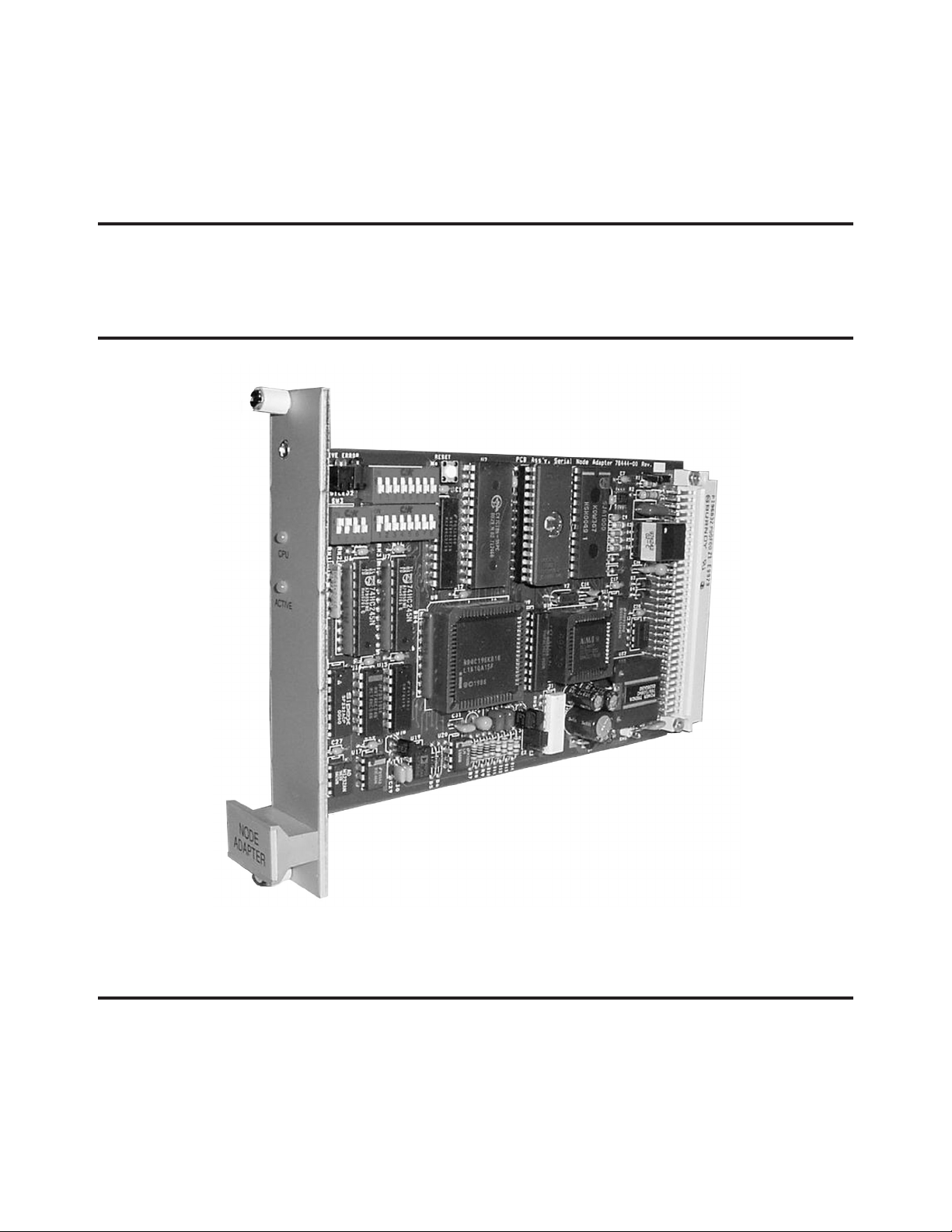
SERIAL NODE ADAPTER
+
MODEL: LECU4012-00 & 78553-00
IMPORTANT: Before using this equipment, carefully read SAFETY PRECAUTIONS, starting on
page 1, and all instructions in this manual. Keep
this Service Bulletin for future reference.
Service Manual Price: $ 20.00 (U.S.)

Ransburg
NOTE: This manual has been changed from LN-9238-02.2 to revision LN-9238-02.3. Reasons for
this change are noted under "Manual Change Summary" inside the back cover.
Serial Node Adapter/Serial Node Adapter +
LN-9238-02.3

Serial Node Adapter/Serial Node Adapter + - Contents
CONTENTS
SAFETY:
Ransburg
PAGE
1-5
SAFETY PRECAUTIONS............................................................................................................
HAZARDS / SAFEGUARDS.......................................................................................................
INTRODUCTION:
GENERAL DESCRIPTION.........................................................................................................
SPECIFICATIONS......................................................................................................................
MODES OF OPERATION..........................................................................................................
INSTALLATION:
CONNECTIONS AND CONFIGURATIONS...............................................................................
PRINTED CIRCUIT BOARD......................................................................................................
SW1, SW2, SW3 SWITCHES....................................................................................................
OPERATION:
TABLE 1 - MICROPAK MODE
BLOCK TRANSFER WRITES................................................................................................
BLOCK TRANSFER READS..................................................................................................
BLOCK TRANSFER READS STATUS WORD DEFINITION.................................................
DISCRETE OUTPUT CONFIGURATION...............................................................................
TABLE 2 - NPB MODE (DIPSWITCH SW2-1 ON)
BLOCK TRANSFER WRITES................................................................................................
BLOCK TRANSFER READS...................................................................................................
MICROPAK STATUS WORD DEFINITION............................................................................
ATOMIZER STATUS WORD DEFINITION.............................................................................
DISCRETE OUTPUT CONFIGURATION...............................................................................
TABLE 3 - FLEX MODE (DIPSWITCH SW2-1 & SW2-5 ON)
BLOCK TRANSFER WRITES.................................................................................................
BLOCK TRANSFER READS...................................................................................................
AIRTRONICS FLOW TOLERANCE WORD DEFINITION......................................................
BLOCK TRANSFER READ - MOTHERBOARD 0 CONFIGURATION..................................
BLOCK TRANSFER READ - MOTHERBOARD 1 CONFIGUARTION..................................
BLOCK TRANSFER READ - MOTHERBOARD 2 CONFIGURATION..................................
BLOCK TRANSFER READ - MOTHERBOARD 3 CONFIGURATION..................................
BLOCK TRANSFER READ MICROPAK WORD DEFINITION.............................................
BLOCK TRANSFER READ ATOMIZER MODULE WORD DEFINITION.............................
BLOCK TRANSFER READ AIRTRONIC MODULE WORD DEFINITION............................
BLOCK TRANSFER READ ANALOG MODULE STATUS WORD DEFINITION....
DISCRETE OUTPUT CONFIGURATION..............................................................................
DISCRETE INPUT CONFIGURATION..................................................................................
1
2-5
6-8
6
6
7-8
9-11
9-10
10
11
12-34
12
13
14
15
16
16
17
17
17
18
19
20
20
20
21
21
22
22
23
23
24-25
26
LN-9238-02.3

Ransburg
OPERATION (CONT.):
Serial Node Adapter/Serial Node Adapter + - Contents
PAGE
12-34
APPENDIX 1 - FLEXIBLE 1/4 RACK MOTHERBOARD SYSTEM............................................
ASSEMBLY 78145-00..................................................................................................................
ASSEMBLY 78147-00..................................................................................................................
COMMUNICATION - DISCRETE WIRING.................................................................................
COMMUNICATION - REMOTE I/O.............................................................................................
FLEXIBLE 1/4 RACK RACK MOTHERBOARD SYSTEM.........................................................
CONFIGURATION WORD CONSTRUCTION..........................................................................
MAINTENANCE
TROUBLESHOOTING GUIDE...................................................................................................
PARTS IDENTIFICATION:
PARTS LIST................................................................................................................................
WARRANTY POLICIES:
LIMITED WARRANTY.................................................................................................................
27
27
28-30
30
30
31
32-34
35
35
36
36
37
37
LN-9238-02.3

Serial Node Adapter/Serial Node Adapter + - Safety
SAFETY
Ransburg
SAFETY PRECAUTIONS
Before operating, maintaining or servicing any
Ransburg electrostatic coating system, read and
understand all of the technical and safety literature
for your Ransburg products. This manual contains
information that is important for you to know and
understand. This information relates to USER
SAFETY and PREVENTING EQUIPMENT PROBLEMS. To help you recognize this information, we
use the following symbols. Please pay particular
attention to these sections.
A WARNING! states information to alert you
to a situation that might cause serious injury
if instructions are not followed.
A CAUTION! states information that tells how
to prevent damage to equipment or how to
avoid a situation that might cause minor injury.
A NOTE is information relevant to the procedure in progress.
W A R N I N G
!
The user MUST read and be familiar with the
Safety Secon in this manual and the Ransburg
safety literature therein idened.
This manual MUST be read and thoroughly
understood by ALL personnel who operate, clean
or maintain this equipment! Special care should
be taken to ensure that the WARNINGS and
safety requirements for operang and servicing
the equipment are followed. The user should be
aware of and adhere to ALL local building and re
codes and ordinances as well as NFPA-33 SAFETY
STANDARD, LATEST EDITION, prior to installing,
operang, and/or servicing this equipment.
W A R N I N G
!
While this manual lists standard specications
and service procedures, some minor deviations
may be found between this literature and your
equipment. Differences in local codes and plant
requirements, material delivery requirements,
etc., make such variations inevitable. Compare
this manual with your system installation drawings and appropriate Ransburg equipment manuals to reconcile such differences.
Careful study and continued use of this manual will
provide a better understanding of the equipment
and process, resulting in more efcient operation, longer trouble-free service and faster, easier
troubleshooting. If you do not have the manuals
and safety literature for your Ransburg system,
contact your local Ransburg representative or
Ransburg.
The hazards shown on the following pages
may occur during the normal use of this equipment. Please read the hazard chart beginning on
page 2.
1
LN-9238-02.3
Ransburg
Serial Node Adapter/Serial Node Adapter + - Safety
AREA
Tells where hazards
may occur.
Spray Area
HAZARD
Tells what the hazard is.
Fire Hazard
Improper or inadequate
operation and maintenance
procedures will cause a re
hazard.
Protection against inadvertent arcing that is capable of
causing re or explosion is
lost if any safety interlocks
are disabled during operation. Frequent Power Supply
or Controller shutdown indicates a problem in the system
requiring correction.
SAFEGUARDS
Tells how to avoid the hazard.
Fire extinguishing equipment must be present in
the spray area and tested periodically.
Spray areas must be kept clean to prevent the
accumulation of combustible residues.
Smoking must never be allowed in the spray
area.
The high voltage supplied to the atomizer must
be turned off prior to cleaning, ushing or maintenance.
When using solvents for cleaning:
• Those used for equipment ushing should
have ash points equal to or higher than
those of the coating material.
• Those used for general cleaning must have
ash points above 100°F (37.8°C).
Spray booth ventilation must be kept at the rates
required by NFPA-33, OSHA, country, and local
codes. In addition, ventilation must be maintained during cleaning operations using ammable or combustible solvents.
Electrostatic arcing must be prevented. Safe
sparking distance must be maintained between
the parts being coated and the applicator. A distance of 1 inch for every 10KV of output voltage
is required at all times.
Test only in areas free of combustible material.
Testing may require high voltage to be on, but
only as instructed.
Non-factory replacement parts or unauthor-
ized equipment modications may cause re or
injury.
If used, the key switch bypass is intended for
use only during setup operations. Production
should never be done with safety interlocks disabled.
Never use equipment intended for use in waterborne installations to spray solvent based materials.
The paint process and equipment should be
set up and operated in accordance with NFPA33, NEC, OSHA, local, country, and European
Health and Safety Norms.
LN-9238-02.3
2

Serial Node Adapter/Serial Node Adapter + - Safety
Ransburg
AREA
Tells where hazards
may occur.
Spray Area
HAZARD
Tells what the hazard is.
Explosion Hazard
Improper or inadequate operation and maintenance proce-
dures will cause a re hazard.
Protection against inadvertent
arcing that is capable of caus-
ing re or explosion is lost if
any safety interlocks are disabled during operation.
Frequent Power Supply or
Controller shutdown indicates
a problem in the system requiring correction.
SAFEGUARDS
Tells how to avoid the hazard.
Electrostatic arcing must be prevented. Safe
sparking distance must be maintained between
the parts being coated and the applicator. A distance of 1 inch for every 10KV of output voltage
is required at all times.
Unless specically approved for use in hazardous locations, all electrical equipment must be
located outside Class I or II, Division 1 or 2
hazardous areas, in accordance with NFPA-33.
Test only in areas free of ammable or combustible materials.
The current overload sensitivity (if equipped)
MUST be set as described in the corresponding section of the equipment manual. Protection against inadvertent arcing that is capable
of causing re or explosion is lost if the current
overload sensitivity is not properly set. Frequent power supply shutdown indicates a problem in the system which requires correction.
General Use and
Maintenance
Improper operation or maintenance may create a hazard.
Personnel must be properly
trained in the use of this equipment.
Always turn the control panel power off prior to
ushing, cleaning, or working on spray system
equipment.
Before turning high voltage on, make sure no
objects are within the safe sparking distance.
Ensure that the control panel is interlocked with
the ventilation system and conveyor in accordance with NFPA-33, EN 50176.
Have re extinguishing equipment readily available and tested periodically.
Personnel must be given training in accordance
with the requirements of NFPA-33, EN 60079-0.
Instructions and safety precautions must be
read and understood prior to using this equipment.
Comply with appropriate local, state, and national codes governing ventilation, re protection, operation maintenance, and housekeeping. Reference OSHA, NFPA-33, EN Norms
and your insurance company requirements.
3
LN-9238-02.3
Ransburg
Serial Node Adapter/Serial Node Adapter + - Safety
AREA
Tells where hazards
may occur.
Spray Area /
High Voltage
Equipment
HAZARD
Tells what the hazard is.
Electrical Discharge
There is a high voltage device
that can induce an electrical
charge on ungrounded objects
which is capable of igniting
coating materials.
Inadequate grounding will
cause a spark hazard. A spark
can ignite many coating materials and cause a re or explosion.
SAFEGUARDS
Tells how to avoid the hazard.
Parts being sprayed and operators in the spray
area must be properly grounded.
Parts being sprayed must be supported on conveyors or hangers that are properly grounded.
The resistance between the part and earth
ground must not exceed 1 meg ohm. (Refer to
NFPA-33.)
Operators must be grounded. Rubber soled insulating shoes should not be worn. Grounding
straps on wrists or legs may be used to assure
adequate ground contact.
Operators must not be wearing or carrying any
ungrounded metal objects.
When using an electrostatic handgun, operators
must assure contact with the handle of the applicator via conductive gloves or gloves with the
palm section cut out.
NOTE: REFER TO NFPA-33 OR SPECIFIC
COUNTRY SAFETY CODES REGARDING
PROPER OPERATOR GROUNDING.
All electrically conductive objects in the spray
area, with the exception of those objects required by the process to be at high voltage, must
be grounded. Grounded conductive ooring
must be provided in the spray area.
Always turn off the power supply prior to ushing, cleaning, or working on spray system equipment.
Unless specically approved for use in hazardous locations, all electrical equipment must be
located outside Class I or II, Division 1 or 2 hazardous areas, in accordance with NFPA-33.
LN-9238-02.3
4
Serial Node Adapter/Serial Node Adapter + - Safety
Ransburg
AREA
Tells where hazards
may occur.
Electrical
Equipment
HAZARD
Tells what the hazard is.
Electrical Discharge
High voltage equipment is utilized in the process. Arcing
in the vicinity of ammable or
combustible materials may oc-
cur. Personnel are exposed to
high voltage during operation
and maintenance.
Protection against inadvertent
arcing that may cause a re or
explosion is lost if safety circuits
are disabled during operation.
Frequent power supply shutdown indicates a problem in the
system which requires correction.
An electrical arc can ignite coat-
ing materials and cause a re or
explosion.
SAFEGUARDS
Tells how to avoid the hazard.
Unless specically approved for use in hazardous locations, the power supply, control cabinet,
and all other electrical equipment must be located outside Class I or II, Division 1 and 2 hazardous areas in accordance with NFPA-33 and EN
50176.
Turn the power supply OFF before working on
the equipment.
Test only in areas free of ammable or combustible material.
Testing may require high voltage to be on, but
only as instructed.
Production should never be done with the safety
circuits disabled.
Before turning the high voltage on, make sure no
objects are within the sparking distance.
Toxic Substances
Spray Area
Certain material may be
harmful if inhaled, or if there is
contact with the skin.
Explosion Hazard –
Incompatible Materials
Halogenated hydrocarbon sol-
vents for example: methylene
chloride and 1,1,1,-Trichloroethane are not chemically compatible with the aluminum that
might be used in many system
components. The chemical
reaction caused by these solvents reacting with aluminum
can become violent and lead to
an equipment explosion.
Follow the requirements of the Material Safety
Data Sheet supplied by coating material manufacturer.
Adequate exhaust must be provided to keep the
air free of accumulations of toxic materials.
Use a mask or respirator whenever there is a
chance of inhaling sprayed materials. The mask
must be compatible with the material being
sprayed and its concentration. Equipment must
be as prescribed by an industrial hygienist or
safety expert, and be NIOSH approved.
Aluminum is widely used in other spray application equipment - such as material pumps,
regulators, triggering valves, etc. Halogenated
hydrocarbon solvents must never be used with
aluminum equipment during spraying, ushing,
or cleaning. Read the label or data sheet for the
material you intend to spray. If in doubt as to
whether or not a coating or cleaning material is
compatible, contact your coating supplier. Any
other type of solvent may be used with aluminum
equipment.
5
LN-9238-02.3

Ransburg
INTRODUCTION
Serial Node Adapter/Serial Node Adapter + - Introduction
GENERAL DESCRIPTION
This service manual covers both the Serial Node
Adapter and Serial Node Adapter Plus. The
Plus version does everything the original Node
Adapter does and has added capabilities such as
certain I/O signals may be handled either via A-B
Remote I/O or discretely. In general, this manual
will address the two as one module and point out
the additional capabilities of the Node Adapter
Plus where applicable.
The Serial Node Adapter / Serial Node Adapter
+ Modules have three parts: 1) Allen Bradley
remote I/O (RIO) interface, 2) central processor,
and 3) serial input/output circuits.
The RIO interface contains some Allen-Bradley
(A-B) components which are licensed to Ransburg.
These are designed specically to communicate
with the proprietary protocol of the RIO serial
link. The central component of this block is an
application specic IC (ASIC) which is capable
of formatting the RIO information for use by the
central processor. The termination of the RIO
cable is made to the motherboard at the rear of
the Serial Node Adapter + Module location.
SPECIFICATIONS
Environmental / Physical
Operating Temperature: 0° to 55°C
Storage Temperature: -40°C to 75°C
Humidity: 95% Non-Condensing
Size: 100 x 160mm
Eurocard module,
25mm wide
Electrical
Power Required: 24 Vdc at 150 mA Max.
The core of the central processor is an 8032
microprocessor which communicates with the
Allen-Bradley ASIC. The 8032 provides an RS232 port from which diagnostic functions are
accomplished via internal “debugger” software.
The main software program, which includes the
“debugger” functions, is contained in an Erasable
Programmable Read-Only Memory (EPROM).
The serial I/O circuits are the interface to the other
Eurocard modules in the control rack or racks.
The Serial Node Adapter + uses two-wire serial
(CANBus) bus communication for this, and all
associated modules are equipped to receive and
send information on this bus.
LN-9238-02.3
6

Serial Node Adapter/Serial Node Adapter + - Introduction
Ransburg
MODES OF OPERATION
The Serial Node Adapter/Serial Node Adapter +
has three modes of operation, determined by what
modules need to be operated. The three modes
are: 1) MicroPak, 2) NPB (1 MicroPak, 1 Serial
Atomizer), and 3) Flex mode.
MicroPak Mode
MicroPak mode is for communication with the
MicroPak only, up to four units. This mode is
selected by setting SerNA dipswitch SW2-1 to
OFF. SW2, positions 5, 6, 7, and 8 must be set
to OFF. PLC data mapping information is shown
in Table 1 of the PLC I/O section.
NPB Mode
Node Per Bell mode communicates with one
MicroPak and one Serial Atomizer module and
is selected by setting SerNA dipswitch SW2-1 to
ON. SW2, positions 5, 6, 7, and 8 must be set to
OFF. PLC data mapping information is shown in
Table 2 of the PLC I/O section.
Flex Mode
Beginning with Serial Node Adapter/Serial Node
Adapter + version 2.02 software, this module has
the capability of communicating with one MicroPak
and any combination of Serial Atomizer (SerAT),
and Serial Digital (SerDG) modules, up to a total
of 12 modules. Note: Serial Atomizer must
have version 3.0 or higher Eprom (77118-05)
and it's SW2-4 in ON position. Space is also
reserved for Serial Analog (SerAN) modules, presently under development. This is the FLEX mode
of operation. The new version 2.02 software is
completely compatible with the old MicroPak and
Node Per Bell modes as long as the Serial Node
Adapter/ Serial Node Adapter + dipswitch SW2
is set correctly. For these older modes, SW2,
position 5, 6, 7, and 8 must be set OFF, as is currently done on Serial Node Adapter modules with
software earlier than 2.02. With these settings,
the Serial Node Adapter/Serial Node Adapter +
looks the same to the PLC and other modules as
the older versions.
determine what module is in what location. It will
then read a group of three conguration words,
which are programmed into Block Transfer Writes
from the PLC. (The instructions for making up
these conguration words are given in Appendix
1). While making this comparison, the module will
ash its "CPU" indicator. If these two congurations are the same, the Serial Node Adapter/Serial
Node Adapter + will begin communication with the
local modules, and the "CPU" indicator will stay
on solid. This method of redundant conguration
checking will prevent data from being sent to the
wrong module in case of a faulty module or one
having been removed. (PLC data mapping information is shown in Table 3 of the PLC I/O Section.)
Flex Mode Settings
The setting of the four dipswitches, SW2, 5-8 is
critical to proper operation. (See Figure 6 entitled
"SW1, SW2, and SW3 Switches". ) In order to enable FLEX mode, SW2-1 must be ON. If SW2 - 1
is ON, the positions 5-8 mean:
Position 5:
OFF means the mode is determined by SW2-1,
either MicroPak only or NPB (one MicroPak and
one Serial Atomizer). In this mode the Serial
Node Adapter version 2.02 is backward compat-
ible with existing applications.
ON (with position 1 ON) means the new FLEX
mode. This means the PLC programmer must
include the conguration information in the rst
three words of BTW.
Position 6 and 7:
These are used, as shown in Figure 1, to set the
logical rack size of the node adapter as it appears
to the PLC. The number of SerDG modules on
the bus determines the size.
Again, the Serial Node Adapter could do this
function automatically, but a faulty module or
modules removed could create an erroneous
reading.
In the FLEX mode, on power up, before sending
data to modules, the Serial Node Adapter/Serial
Node Adapter + will read the local serial bus and
7
LN-9238-02.3

Ransburg
# SerDG
Modules
Serial Node Adapter/Serial Node Adapter + - Introduction
Rack Size
0 - 2
3 - 6
7 - 10
11 - 12
Figure 1: Position 6 & 7 Rack Size Settings
Position 8:
This position enables a Bus Agreement Override
mode that allows the Serial Node Adapter/Serial
Node Adapter + to communicate between the
internal bus and the PLC when the two congurations do not agree. In this mode the Serial Node
Adapter/Serial Node Adapter + will use the bus
conguration specied in the BTW conguration
word.
1/4
1/2
3/4
Full
NOTE
> This mode should only be used for
troubleshooting. It is possible for data to
be communicated to the wrong module.
For this reason, bit 14 is set in the BTR
words 0, 1, and 2, indicating this
mode has been entered. The "CPU" indicator on the Serial Node Adapter/Serial
Node Adapter + will ash also.
LN-9238-02.3
Figure 1: AdaptaFlow System Rack
8
Serial Node Adapter/Serial Node Adapter + - Installation
INSTALLATION
Ransburg
CONNECTIONS AND
CONFIGURATIONS
Input Power
Required input power is regulated 24 Vdc which
is supplied by the motherboard of the rack which
contains the Serial Node Adapter. An on-board
dc-dc converter makes 5 Vdc for the module's logic
level circuits. The Serial Node Adapter + may be
installed in any one of three motherboards. The
power connections for each are shown in Figure 2.
Motherboard
LECU4014-02
78145-00
78149-00
Figure 2: Input Power Connections
+24 Vdc
J10 - 1
J7 - 3 (+24)
J16 - 3 (+24)
24 Vdc com
J10 - 2
J7 - 4 (GND)
J16 - 4 (GND)
The RIO cable may be "daisy-chained" from
one node to another per Allen-Bradley installa-
tion specications. Where a termination resistor
is specied, usually the last termination point in
a chain, install the appropriate resistor directly
across ""BLU" and "CLR" on the RIO connector.
NOTE
> Switch SW3, positions 1 and 2 must
be in the OFF position for full RIO communication.
Remote I/O With Certain
Discrete Inputs (Serial Node
Adapter + Only)
Certain inputs may be controlled independent of
the Remote I/O communication in this mode set
by switch SW3, positions 1 and 2. (See Figure 6)
These inputs are KV Set and Speed Set (analogs)
and HV ON, Fluid Trigger and Di-dt inhibit (24V
digital). The pin connections for these signals are:
Remote I/O
The connection of the Allen-Bradley Remote
I/O (RIO) is made to the connector labeled RIO.
This connector is located at the top of each of the
above motherboards. The RIO cable wires are
connected as shown below.
RIO Wire
Blue
Bare
Clear
Figure 3: RIO Cable Wire Connections
9
RIO
Terminal
BLU
SHLD
CLR
Inputs
KV Setpoint
Speed Setpoint
HV On
Fluid Trigger
Di/dt Inhibit
Spare
Figure 4: RIO Discrete Inputs
Pin
Connections
5A
4C
20C
17C
15C
18C
76111-XX Ca-
ble Assy. Wire
Color
YEL
BRN
BLU/BLA
RED/BLA
ORG
----
LN-9238-02.3

Ransburg
Serial Node Adapter/Serial Node Adapter + - Installation
A 76111-XX I/O cable may be used to access the
pins in Figure 4.
The analog signal scaling may be either 0-10
Vdc or 4-20 mAdc as selected by switch SW3-3.
Digital inputs may be either 24 Vdc source (set
Jumper E2 in 2-3 position) or sink to ground (set
Jumper E2 in 1-2 position).
NOTE
> SW3 installed only in the Serial Node
Adapter + version.
Serial Bus Connection To Other
Motherboards
The Serial Node Adapter/Serial Node Adapter +
communicates to other modules in the rack via the
local Serial Bus. If more than one motherboard
is communicating with the Serial Node Adapter/
Serial Node Adapter +, the Serial Bus must be
jumpered to motherboards not having a Serial
Node Adapter. This is done by a short section
of shielded twisted pair cable between connectors labeled “Serial” or “CAN”, and being sure to
observe the (+) to (+) convention.
A bus termination resistor (120 ohms, 1/2w) must
be connected across the (+) and (-) terminals of
the nal cable termination.
Serial Node Adapter/Serial
Node Adapter + Addressing/
Conguration
The Serial Node Adapter/Serial Node Adapter +
must be set for the appropriate RIO address. The
rack address and starting quarter are set by switch
SW1 as shown in Figure 6. The Operating Mode,
Last State, Baud Rate, and Rack Size are set by
positions 1-8 on switch SW2 as shown in Figure 6.
LN-9238-02.3
Figure 5: Printed Circuit Board
10

Serial Node Adapter/Serial Node Adapter + - Installation
Ransburg
11
Figure 6: SW1, SW2, and SW3 Switches
LN-9238-02.3

Ransburg
Serial Node Adapter/Serial Node Adapter + - Operation
OPERATION
TABLE 1 - SERIAL NODE ADAPTER + LECU4012-00
PLC I/O - MICROPAK MODE
BLOCK TRANSFER WRITES
BTW
WORD
MODULE
CONFIGURATION
0
1
2
3
4
5
6
7
8
9
MicroPak #1
MicroPak #1
MicroPak #1
----
MicroPak #2
MicroPak #2
MicroPak #2
----
MicroPak #3
MicroPak #3
High Voltage Setpoint (Value of 0-100 corresponds to 0-100 KV)
Current Limit Setpoint
HP404 Cascade: 0-250 corresponds to 0-250 µA
RP1000 Ccascade: 0-1000 corresponds to 0-1000 µA
Di/dt Setpoint (Value of 0-9 corresponds to max. to min. sensitivity)
(Not Used)
High Voltage Setpoint (Value of 0-100 corresponds to 0-100 KV)
Current Limit Setpoint
HP404 Cascade: 0-250 corresponds to 0-250 µA
RP1000 Cascade: 0-1000 corresponds to 0-1000 µA
Di/dt Setpoint (Value of 0-9 corresponds to max. to min. sensitivity)
(Not Used)
High Voltage Setpoint (Value of 0-100 corresponds to 0-100 KV)
Current Limit Setpoint
HP404 Cascade: 0-250 corresponds to 0-250 µA
RP1000 Cascade: 0-1000 corresponds to 0-1000 µA
LN-9238-02.3
10
11
12
13
14
15
MicroPak #3
----
MicroPak #4
MicroPak #4
MicroPak #4
----
Di/dt Setpoint (Value of 0-9 corresponds to max. to min. sensitivity)
(Not Used)
High Voltage Setpoint (Value of 0-100 corresponds to 0-100 KV)
Current Limit Setpoint
HP404 Ccascade: 0-250 corresponds to 0-250 µA
RP1000 Cascade: 0-1000 corresponds to 0-1000 µA
Di/dt Setpoint (Value of 0-9 corresponds to max. to min. sensitivity)
(Not Used)
12

Serial Node Adapter/Serial Node Adapter + - Operation
Table 1 - Serial Node Adapter + LECU4012-00
PLC I/O - MicroPak Mode (Cont.)
BLOCK TRANSFER READS
BTR
WORD
MODULE CONFIGURATION
Ransburg
0
1
2
3
4
5
6
7
8
9
MicroPak #1
MicroPak #1
MicroPak #1
MicroPak #2
MicroPak #2
MicroPak #2
MicroPak #3
MicroPak #3
MicroPak #3
MicroPak #4
High Voltage Feedback (Value of 0-100 corresponds to 0-100 KV)
Current Feedback
HP404 Cascade: 0-250 corresponds to 0-250 µA
RP1000 Cascade: 0-1000 corresponds to 0-1000 µA
Status Word *
High Voltage Feedback (Value of 0-100 corresponds to 0-100 KV)
Current Feedback
HP404 Cascade: 0-250 corresponds to 0-250 µA
RP1000 Cascade: 0-1000 corresponds to 0-1000 µA
Status Word *
High Voltage Feedback (Value of 0-100 corresponds to 0-100 KV)
Current Feedback
HP404 Cascade: 0-250 corresponds to 0-250 µA
RP1000 Cascade: 0-1000 corresponds to 0-1000 µA
Status Word *
High Voltage Feedback (Value of 0-100 corresponds to 0-100 KV)
10
11
* See "Status Word Denition" on next page.
13
MicroPak #4
MicroPak #4
Current Feedback
HP404 Cascade: 0-250 corresponds to 0-250 µA
RP1000 Cascade: 0-100 corresponds to 0-1000 µA
Status Word *
LN-9238-02.3

Ransburg
Serial Node Adapter/Serial Node Adapter + - Operation
Table 1 - Serial Node Adapter + LECU4012-00
PLC I/O - MicroPak Mode (Cont.)
BLOCK TRANSFER READS STATUS WORD DEFINITION
BIT
00
01
02
03
04
05
06
07
08
09
10
STATUS
High Voltage Held In Reset
High Voltage Ready
High Voltage On
Di/dt Fault
High Voltage Overload
Feedback Fault
Sequence
Local
Fluid Trigger Active
Air Trigger Active
Di/dt Enabled
13-15
LN-9238-02.3
11
12
KV Out of Tolerance
Low Output Current
(Not Used)
14

Serial Node Adapter/Serial Node Adapter + - Operation
Table 1 - Serial Node Adapter + LECU4012-00
PLC I/O MicroPak Mode (Cont.)
DISCRETE OUTPUT CONFIGURATION
WORD/
BIT
MODULE
OUTPUT
Ransburg
0/00-07
0/10
0/11
0/12
0/13
0/14-17
1/00
1/01
1/02
1/03
1/04
05
06
----
MicroPak #1
MicroPak #2
MicroPak #3
MicroPak #4
----
MicroPak #1
MicroPak #1
MicroPak #1
MicroPak #1
MicroPak #2
MicroPak #2
MicroPak #2
(Not Used)
Di/dt Inhibit
Di/dt Inhibit
Di/dt Inhibit
Di/dt Inhibit
(Not Used)
High Voltage On Command
High Voltage Reset
Fluid Trigger
Air Trigger
High Voltage On Command
High Voltage Reset
Fluid Trigger
15
07
10
11
12
13
14
15
16
17
MicroPak #2
MicroPak #3
MicroPak #3
MicroPak #3
MicroPak #3
MicroPak #4
MicroPak #4
MicroPak #4
MicroPak #4
Air Trigger
High Voltage On Command
High Voltage Reset
Fluid Trigger
Air Trigger
High Voltage On Command
High Voltage Reset
Fluid Trigger
Air Trigger
LN-9238-02.3

Ransburg
Serial Node Adapter/Serial Node Adapter + - Operation
Table 2 - SERIAL NODE ADAPTER + LECU4012-00
PLC I/O - NPB MODE (DIPSWITCH SW2-1 ON)
BLOCK TRANSFER WRITES
BTW
WORD
MODULE
CONFIGURATION
0
1
2
3
4
5
MicroPak #1
MicroPak #1
MicroPak #1
----
Atomizer 1
----
High Voltage Setpoint (Value of 0-100 corresponds to 0-100 KV)
Current Limit Setpoint:
HP404 Cascade: 0-250 corresponds to 0-250 µA
RP1000 Cascade: 0-1000 corresponds to 0-1000 µA
Di/dt Setpoint (Value of 0-9 corresponds to max. to min. sensitivity)
(Not Used)
Speed Setpoint:
Liquid: 0-50 corresponds to 0-50 krpm
Powder: 0-250 corresponds to 0-25 krpm
(Not Used)
BLOCK TRANSFER READS
BTW
WORD
0
MODULE
MicroPak
CONFIGURATION
High Voltage Feedback (Value of 0-100 corresponds to 0-100 KV)
LN-9238-02.3
1
2
3
4
5
6
MicroPak
MicroPak
Atomizer 1
Atomizer 1
Atomizer 1
----
Current Feedback:
HP404 Cascade: 0-250 corresponds to 0-250 µA
RP1000 Cascade: 0-1000 corresponds to 0-1000 µA
MicroPak Status Word *
Atomizer Status Word **
Atomizer Drive Pressure (Value of 0-60 corresponds to 0-60 psi)
Speed Feedback:
Liquid: (Value of 0-50 corresponds to 0-50 krpm)
Powder: (Value of 0-250 corresponds to 0-25 krpm)
(Not Used)
16

Serial Node Adapter/Serial Node Adapter + - Operation
Table 2 - Node Adapter + LECU4012-00
PLC I/O - NPB Mode (Dipswitch SW2-1 On) (Cont.)
Ransburg
* MICROPAK STATUS
WORD DEFINITION
BIT
00
01
02
03
04
05
06
07
08
09
10
11
12
STATUS
HV Held In Reset
HV Ready
HV On
Di/dt Fault
HV Overload
Feedback Fault
Sequence
Local
Fluid Trigger Active
Air Trigger Active
Di/dt Enabled
KV Out of Tolerance
Low Output Current
** ATOMIZER STATUS WORD
DEFINITION
BIT
00-07
08
09
10
11
12
13
14
15
STATUS
Bearing Air (8-bits)
Overspeed
Underspeed
Loss of Feedback
Invalid Data Input
Low Bearing Air
Bell Running
Out of Tolerance
(Not Used)
DISCRETE OUTPUT
CONFIGURATION
WORD/
BIT
MODULE
OUTPUT
13-15
* See "Conguration Word Construction" in Appendix 1.
** If no SerAT Modules Installed, next module type moves to this position.
*** See following "Tolerance Word Construction."
17
(Not Used)
0
1/00
1/01
1/02
1/03
1/04
1/05-07
Not Used
MicroPak
MicroPak
MicroPak
MicroPak
MicroPak
Not Used
------
High Voltage On
Command
High Voltage Reset
Fluid Trigger
Air Trigger
Di/dt Inhibit
------
LN-9238-02.3

Ransburg
Serial Node Adapter/Serial Node Adapter + - Operation
Table 3 - Serial Node Adapter + LECU4012-00
PLC I/O - Flex Mode (Dipswitch SW2-1 and SW2-5 On)
BLOCK TRANSFER WRITES
BTW
WORD
MODULE
BTW BLOCK CONFIGURATION
0
1
2
3
4
5
6
7
8
9
X
Motherboard 0
Motherboard 1
Motherboard 2
Motherboard 3
MicroPak
MicroPak
MicroPak
----
SerAT 1**
----
SerAN 1
Conguration word dening Motherboard 0 Modules *
Conguration word dening Motherboard 1 Modules *
Conguration word dening Motherboard 2 Modules *
Conguration word dening Motherboard 3 Modules *
High Voltage Setpoint: (Value of 0-100 corresponds to 0-100 KV)
Current Limit Setpoint:
HP404 Cascade: 0-250 corresponds to 0-250 µA
RP1000 Cascade: 0-1000 corresponds to 0-1000 µA
Di/dt Setpoint (Value of 0-9 corresponds to max. to min. sensitivity)
(Not Used)
Speed Setpoint:
Liquid: 0-50 corresponds to 0-50 krpm
(Additional Serial Atomizer(s) with higher slot addresses)
Channel 1 Setpoint (Value of 10-100 corresponds to 0-90 psi)
X
X
X
X
X
X
* See "Conguration Word Construction" in Appendix 1.
** If no SerAT Modules Installed, next module type moves to this position.
*** See following "Tolerance Word Construction."
LN-9238-02.3
SerAN 1
----
AirTronic 1
AirTronic 1
AirTronic 1
----
Channel 2 Setpoint (Value of 10-100 corresponds to 0-90 psi)
(Additional Serial Analog(s) with higher slot addresses)
Channel 1 Setpoint (Enter in slpm, e.g. to set 85 slpm, enter 85)
Channel 2 Setpoint (Enter in slpm, e.g. to set 85 slpm, enter 85)
High / Low Flow Tolerance (0-15 equals 0-30% of setpoint) ***
(Additional AirTronic modules(s) with higher slot addresses)
18

Serial Node Adapter/Serial Node Adapter + - Operation
Table 3 - Node Adapter + LECU4012-00
PLC I/O - Flex Mode (Dipswitch SW2-1 and SW2-5 On) (Cont.)
BLOCK TRANSFER READS
BTW
WORD
0
MODULE
Motherboard 0
BTR BLOCK CONFIGURATION
Hardware Conguration and Status Bits
Ransburg
1
2
3
4
5
Motherboard 1
Motherboard 2
Motherboard 3
MicroPak
MicroPak
Hardware Conguration and Status Bits
Hardware Conguration and Status Bits
Hardware Conguration and Status Bits
High Voltage Feedback (Value of 0-100 corresponds to 0-100 KV)
Current Feedback:
HP404 Cascade: 0-250 corresponds to 0-250 µA
RP1000 Cascade: 0-1000 corresponds to 0-1000 µA
6
7
8
9
MicroPak
SerAT1 **
SerAT 1
SerAT 1
MicroPak Status Word
Atomizer Status Word
Atomizer Drive Pressure (Value of 0-60 corresponds to 0-60 psi)
Speed Feedback:
Liquid: (Value of 0-50 corresponds to 0-50 krpm)
Powder: (Value of 0-250 corresponds to 0-25 krpm)
X
X
----
SerAN 1
(Additional Serial Atomizer Modules)
Channel 1 Pressure Out
19
X
X
X
X
X
X
X
SerAN 1
----
SerAN (All)
AirTronic 1
AirTronic 1
AirTronic 1
----
Channel 2 Pressure Out
(Additional Serial Analog Modules
Analog Status Word
Channel 1 Actual Flow
Channel 2 Actual Flow
Input Air Line Pressure and Status
(Additional AirTronic Modules)
LN-9238-02.3

Ransburg
Serial Node Adapter/Serial Node Adapter + - Operation
Table 3 - Node Adapter + LECU4012-00
PLC I/O - Flex Mode (Dipswitch SW2-1 and SW2-5 On) (Cont.)
AIRTRONICS FLOW TOLERANCE WORD DEFINITION
BIT
00-03
04-07
08-11
12-15
DEFINITION
CH 1 Low Flow Tolerance, (0-15 equals 0-30% of setpoint)
CH 1 High Flow Tolerance, (0-15 equals 0-30% of setpoint)
CH 2 Low Flow Tolerance, (0-15 equals 0-30% of setpoint)
CH 2 High Flow Tolerance, (0-15 equals 0-30% of setpoint)
BLOCK TRANSFER READ - MOTHERBOARD 0 CONFIGURATION
BIT
00
01
02-03
04-07
DEFINITION
BTW word 0 does not agree with Motherboard 0 Hardware Conguration
Serial Node Adapter is in Override Mode
(Not Used)
Motherboard 0, Slot 2 Module Type
BLOCK TRANSFER READ - MOTHERBOARD 1 CONFIGURATION
LN-9238-02.3
08-11
12-15
BIT
00
01
02-03
04-07
08-11
12-15
Motherboard 0, Slot 1 Module Type
Motherboard 0, Slot 0 Module Type
DEFINITION
BTW word 1 does not agree with Motherboard 1 hardware conguration
Serial Node Adapter is in Override Mode.
(Not Used)
Motherboard 1, Slot 2 Module Type
Motherboard 1, Slot 1 Module Type
Motherboard 1, Slot 0 Module Type
20

Serial Node Adapter/Serial Node Adapter + - Operation
Table 3 - Node Adapter + LECU4012-00
PLC I/O - Flex Mode (Dipswitch SW2-1 and SW2-5 On) (Cont.)
BLOCK TRANSFER READ - MOTHERBOARD 2 CONFIGURATION
Ransburg
BIT
00
01
02-03
04-07
08-11
12-15
DEFINITION
BTW word 2 does not agree with Motherboard 2 hardware conguration
Serial Node Adapter is in Override Mode.
(Not Used)
Motherboard 2, Slot 2 Module Type
Motherboard 2, Slot 1 Module Type
Motherboard 2, Slot 0 Module Type
BLOCK TRANSFER READ - MOTHERBOARD 3 CONFIGURATION
BIT
00
01
DEFINITION
BTW word 3 does not agree with Motherboard 3 hardware conguration
Serial Node Adapter is in Override Mode.
21
02-03
04-07
08-11
12-15
(Not Used)
Motherboard 3, Slot 2 Module Type
Motherboard 3, Slot 1 Module Type
Motherboard 3, Slot 0 Module Type
LN-9238-02.3

Ransburg
Serial Node Adapter/Serial Node Adapter + - Operation
Table 3 - Node Adapter + LECU4012-00
PLC I/O - Flex Mode (Dipswitch SW2-1 and SW2-5 On) (Cont.)
BLOCK TRANSFER READ
MICROPAK WORD
DEFINITION
BIT STATUS
00
01
02
03
04
05
06
07
08
High Voltage In Reset
High Voltage Ready
High Voltage On
Di/dt Fault
High Voltage Overload
Feedback Fault
Seqence Mode
Local Mode
Fluid Trigger On
BLOCK TRANSFER READ
ATOMIZER MODULE WORD
DEFINITION
BIT
00-07
08
09
10
11
12
13
14
15
STATUS
Bearing Air (8-Bit)
Overspeed
Underspeed
Loss of Feedback
Invalid Data Input
Low Bearing Air
Bell Running
Out of Tolerance
(Not Used)
09
10
11
12
13-15
Air Trigger On
Di/dt Enabled
KV Out of Tolerance
Low Output Current
(Not Used)
LN-9238-02.3
22

Serial Node Adapter/Serial Node Adapter + - Operation
Table 3 - Node Adapter + LECU4012-00
PLC I/O - Flex Mode (Dipswitch SW2-1 and SW2-5 On)
Digital Modules, No AirTronic Modules (Cont.)
Ransburg
BLOCK TRANSFER READ
8
AIRTRONIC MODULE WORD
DEFINITION
BIT
00-07
08
09
10
11-15
STATUS
Input Pressure (8 Bit)
Channel 1 in Local
Channel 2 in Local
Slave Mode
(Not Used)
BLOCK TRANSFER READ
ANALOG MODULE WORD
DEFINITION
BIT
00-07
08
09
10
11
12-15
STATUS
Error Check (All 1)
1/4 Rack 0 In Local
1/4 Rack 1 In Local
1/4 Rack 2 In Local
1/4 Rack 3 In Local
(Not Used)
23
LN-9238-02.3

Ransburg
Serial Node Adapter/Serial Node Adapter + - Operation
Table 3 - Node Adapter + LECU4012-00
PLC I/O - Flex Mode (Dipswitch SW2-1 and S2-5 On)
Digital Modules, No AirTronic Modules (Cont.)
DISCRETE OUTPUT CONFIGURATION
WORD/
BIT
MODULE OUTPUT
0/00-07
0/10
11
12
13
14
15
16
17
1/00
01
02
03
----
MicroPak
MicroPak
MicroPak
MicroPak
MicroPak
----
----
Digital
Digital (1)
Digital (1)
Digital (1)
Digital (1)
(Not Used)
High Voltage On Command
High Voltage Reset
Fluid Trigger
Air Trigger
Di/dt Inhibit
(Not Used)
(Not Used)
Manual Lock-out
Valve 1
Valve 2
Valve 3
Valve 4
04
05
06
07
Add additional outputs to Digital Module as required.
If AirTronic Modules are present, see the following.
LN-9238-02.3
Digital (1)
Digital (1)
Digital (1)
Digital (1)
Valve 5
Valve 6
Valve 7
Valve 8
24

Serial Node Adapter/Serial Node Adapter + - Operation
Table 3 - Node Adapter + LECU4012-00
PLC I/O - Flex Mode (Dipswitch SW2-1 and SW2-5 On)
AirTronic Modules, No Digital Modules (Cont.)
DISCRETE OUTPUT CONFIGURATION
WORD/
BIT
MODULE
OUTPUT
Ransburg
00/07
0/10
11
12
13
14
15
16
17
1/00
01
02
03
----
MicroPak
MicroPak
MicroPak
MicroPak
MicroPak
All AirTronic
All AirTronic
----
AirTronic (1)
AirTronic (1)
AirTronic (1)
AirTronic (1)
(Not Used)
High Voltage on Command
High Voltage Reset
Fluid Trigger
Air Trigger
Di/dt Inhibit
Channel 1 Fault Inhibit
Channel 2 Fault Inhibit
(Not Used)
Trigger Channel 1
Hold Channel 1
Trigger Channel 2
Hold Channel 2
25
04
05
06
07
1/10-17
If Digital Modules and AirTronic Modules are together on the same Node Adapter bus,
data for all Digital Modules is addressed before the data for the AirTronic Modules.
AirTronic (2)
AirTronic (2)
AirTronic (2)
AirTronic (2)
AirTronic
Trigger Channel 1
Hold Channel 1
Trigger Channel 2
Hold Channel 2
(Additional AirTronic Modules)
LN-9238-02.3

Ransburg
Serial Node Adapter/Serial Node Adapter + - Operation
Table 3 - Node Adapter + LECU4012-00
PLC I/O - Flex Mode (Dipswitch SW2-1 and SW2-5 On) (Cont.)
DISCRETE INPUT CONFIGURATION
WORD/
BIT
MODULE INPUT
0/00-07
0/10
11
12
13
14
15
16
17
1/00
01
02
03
----
AirTronic 1
AirTronic 1
AirTronic 1
AirTronic 1
AirTronic 1
AirTronic 1
AirTronic 1
AirTronic 1
AirTronic 2
AirTronic 2
AirTronic 2
AirTronic 2
(Not Used)
Channel 1 Low Tolerance Alarm
Channel 1 High Tolerance Alarm
Channel 2 Low Tolerance Alarm
Channel 2 High Tolerance Alarm
Input Pressure Low Alarm (<75 psi)
Input Pressure High Alarm (>95 psi)
Internal Communication Fault
Hose Fault
Channel 1 Low Tolerance Alarm
Channel 1 High Tolerance Alarm
Channel 2 Low Tolerance Alarm
Channel 2 High Tolerance Alarm
04
05
06
07
1/10-17
Add additional inputs from AirTronics Module as required.
* See "Conguration Word Construction" in Appendix 1.
** If no SerAT Modules Installed, next module type moves to this position.
*** See following "Tolerance Word Construction."
LN-9238-02.3
AirTronic 2
AirTronic 2
AirTronic 2
AirTronic 2
AirTronic 3
Input Pressure Low Alarm (<75 psi)
Input Pressure High Alarm (>95 psi)
Internal Communication Fault
Hose Fault
(Additional AirTronic Modules)
26

Serial Node Adapter/Serial Node Adapter + - Operation
Ransburg
APPENDIX 1
FLEXIBLE 1/4 RACK
MOTHERBOARD SYSTEM
The 1/4 rack motherboards, 78145-00, 78147-00,
and 78149-00 will allow for exible application of
Serial Pneumatic Modules including Serial Atomizer (SerAT), AirTronic, Serial Digital (SerDG),
Cascading Digital (CCDG), and when available,
Serial Analog (SerAN) modules. Each motherboard has three slots, which will be referred to as
slots 0, 1, and 2, when viewed left to right, from
the module insertion side.
Specic Applications
1. Assembly 78145-00:
Slot 0 is reserved for Serial Node Adapter,
LECU4012-00 or Discrete I/O module,
76037-03 or -04. Note that a blank cover,
PNA10211-02 is required to cover an empty
space (module is 1" wide and the slot width is
1.4" wide). Slots 1 and 2 will accept any
combination of SerAT, AirTronic, SerDG, and
SerAN modules.
2. Assembly 78147-00:
For use when Serial Node Adapter is located
in another motherboard or for discretely wired
applications. Slots 0, 1, and 2 are identical and
will accept any combination of SerAT, Air-Tronic,
SerDG, and SerAN modules. If I/O communication is by internal serial bus, a jumper cable
must be connected to the serial bus source.
27
Figure 7: Assembly 78145-00
LN-9238-02.3

Ransburg
Serial Node Adapter/Serial Node Adapter + - Operation
LN-9238-02.3
Figure 8: Assembly 78147-00
28

Serial Node Adapter/Serial Node Adapter + - Operation
Ransburg
29
Figure 9: Assembly 78147-00
LN-9238-02.3

Ransburg
3. Assembly 78149-00:
This is reserved for the Cascading Digital
module (CCDG). The pneumatic connector is
unique to this module. Slots 0, 1, and 2 are
identical. I/O communication is via internal serial
bus (use cable to jumper to serial bus source)
or by discrete wiring to the module's terminal
strip on the rear.
Serial Node Adapter/Serial Node Adapter + - Operation
COMMUNICATION DISCRETE WIRING
1. Serial Atomizer (SerAT) - must be paired with
Discrete I/O module (one DIO per SerAT). Connections are made via the Discrete I/O cable.
2. Serial Digital (SerDG), Cascading Digital
(CCDG) - will accept 24 Vdc signals to 8 pin
terminal strips on rear of motherboard, behind
each slot. Module must be set via dipswitch for
this I/O conguration. The I/O for both Serial and
Cascading Digital is identical.
3. Serial Analog (SerAN) - will accept 0-10 Vdc or
4-20 mA signals to 8 pin terminal strips on rear of
motherboard, behind each slot. Module must be
set via dipswitch for this I/O conguration.
COMMUNICATION REMOTE I/O
The Allen-Bradley RIO via the Serial Node Adapter
can talk to any combination of up to 12 SerAT,
SerDG, CCDG, and SerAN modules via its local
CANBus. This requires Serial Node Adapter
Eprom Part #77128-04 (Version 2.02 or higher).
The local CANBus can consist of up to 4, 1/4 rack
motherboards connected together. Each motherboard has an addressing switch, which must be
set to from 0 to 3, so that each slot has a unique
bus address. The PLC data mapping for the FLEX
mode is shown in the following gures.
LN-9238-02.3
30

Serial Node Adapter/Serial Node Adapter + - Operation
FLEXIBLE 1/4 RACK
MOTHERBOARD SYSTEM
Conguration Word Construction
Ransburg
The above shows a group of any four of the
78145, 147, or 149 motherboards. The rotary
address switch sets an address number 0, 1, 2,
or 3 for that motherboard. Each motherboard
communicating with a given Serial Node Adapter
must have a different address number. This address number is completely independent of the
physical location of the motherboard. Each slot
in these motherboards has a number assigned
to it which is determined by which slot and which
mother-board.
The conguration words entered in the BTW's
dene what modules are located in each motherboard. Word 0 denes what modules are located
in the motherboard with address 0, word 1 denes
motherboard 1, etc. The modules are assigned an
ID number that is used to identify it and its position
in the motherboard. These ID's are:
MODULE IDENTIFICATION
NUMBERS
MODULE
MODULE
MicroPak
Serial Atomizer
Serial Digital
Serial Analog
AirTronic
TYPE ID#
0001
0010
0011
0100
0101
31
LN-9238-02.3

Ransburg
The BTW's used for conguration words would
look like this:
Serial Node Adapter/Serial Node Adapter + - Operation
BTW'S USED FOR CONFIGURATION WORDS
WORD/BIT
0 - Motherboard 0
1 - Motherboard 1
2 - Motherboard 2
3 - Motherboard 3
15 14 13 12
Slot 0
Slot 0
Slot 0
Slot 0
11 10 9 8
Slot 1
Slot 1
Slot 1
Slot 1
7 6 5 4
Slot 2
Slot 2
Slot 2
Slot 2
3 2 1 0
N/A
N/A
N/A
N/A
For Example:
For the above example the conguration words are:
BTW'S USED FOR CONFIGURATION WORDS
WORD/BIT
0 - Motherboard 0
1 - Motherboard 1
2 - Motherboard 2
3 - Motherboard 3
LN-9238-02.3
15 14 13 12
0 0 1 0
0 1 0 1
0 0 1 1
0 0 1 1
11 10 9 8
0 0 1 0
0 1 0 0
0 0 1 1
0 0 1 1
7 6 5 4
0 1 0 1
0 1 0 0
0 0 1 1
0 0 1 1
3 2 1 0
N/A
N/A
N/A
N/A
32

Serial Node Adapter/Serial Node Adapter + - Operation
If the address 0 motherboard is a 78145-00, having a Serial Node Adapter in the leftmost slot,
the procedure is the same. There is simply no
contribution to a conguration word from this slot
(Word 0, bits 12-15 are zero).
If any of the slots are empty, simply enter zero
for that slot.
With MicroPak
When a MicroPak is used, there is no change to
the conguration system. There is no conguration word used for the MicroPak, but MicroPak
switch SW7 must be set at the default, address
1 (positions 1, 2, and 3 ON, position 4 OFF). In
the following example, a MicroPak motherboard
has been added to this combination.
Ransburg
The conguration words are identical to that above.
Note that at least one of the motherboards in this
example must be located in another physical rack.
The above examples show a maximum number
of modules communicating with one Serial Node
Adapter. A more practical system (single bell)
might be:
33
LN-9238-02.3

Ransburg
The conguration words for this example are:
BTW'S USED FOR CONFIGURATION WORDS
Serial Node Adapter/Serial Node Adapter + - Operation
WORD/BIT
0 - Motherboard 0
1 - Motherboard 1
2 - Motherboard 2
3 - Motherboard 3
15 14 13 12
0 0 1 0
0 0 0 0
0 0 0 0
0 0 0 0
11 10 9 8
0 0 0 0
0 0 0 0
0 0 0 0
0 0 0 0
7 6 5 4
0 1 0 1
0 0 0 0
0 0 0 0
0 0 0 0
3 2 1 0
N/A
N/A
N/A
N/A
LN-9238-02.3
34

Serial Node Adapter/Serial Node Adapter + - Maintenance
MAINTENANCE
TROUBLESHOOTING GUIDE
SERIAL NODE ADAPTER + LED INDICATORS
Ransburg
ACTIVE
LED
ON
OFF
BLINK
ON
OFF
CPU
LED
ON
ON
ON
BLINK
OFF
FAULT DESCRIPTION POSSIBLE CAUSE
Normal Operation
Serial Node Adapter not
communicating with Remote I/O
Serial Node Adapter is not
controlling I/O
Checking Conguration
No Serial Node Adapter activity
----
1. RIO cable not connected
2. Incorrect dipswitch settings on Serial
Node Adapter for Baud rate, Address or
Starting Quarter
1. PLC in program mode
2. Another Node with same address on
RIO
1. Normal during power-up
2. Flex Mode - after power-up, indicates
conguration word does not match
installed hardware.
1. No power to Serial Node Adapter
2. Hardware failure
35
LN-9238-02.3

Ransburg
Serial Node Adapter/Serial Node Adapter + - Parts Identication
PARTS IDENTIFICATION
FLEXIBLE 1/4 RACK MOTHERBOARD SYSTEM - PARTS LIST
PART #
78145-00
78147-00
78149-00
LECU4014-02
76913-01-05
LECU4012-00
78553-00
A10211-02
76037-03
76037-04
76011-00
DESCRIPTION
1/4 Rack Motherboard, Type 0, Serial Node Adapter + Ser. Pneum.
1/4 Rack Motherboard, Type 1, Serial Pneum.
1/4 Rack Motherboard, Type 2, SerCCDG
1/4 Rack Motherboard, Type 3, MicroPak
1/2 Rack Motherboard, Serial Pneum.
Serial Node Adapter
Serial Node Adapter +
Blank Plate, 0.4"
Discrete I/O Module, 0-10V
Discrete I/O Module, 4-20mA
Serial Atomizer Module
LN-9238-02.3
76911-01
76911-02
78499-XX
78497-XX
76111-XX
Cascading Output Serial Digital Module
Serial Digital Module
Rack Assembly, 19" (With Modules)
Rack Assembly, 10" (With Modules)
I/O Cable (for Node Adapter + functions)
36

Serial Node Adapter/Serial Node Adapter + - Warranty Policies
WARRANTY POLICIES
Ransburg
LIMITED WARRANTY
The Ransburg Serial Node Adapter/Serial Node
Adapter + is warranted to be free of defects in
workmanship and material. The terms of this war-
ranty, except as hereinafter provided, extend from
one year from the date of rst installation. This
excludes equipment failures which are the result
of misapplication, misuse, incorrect maintenance,
or normal wear. If, after inspection by Ransburg
a defect is conrmed, we will at our option repair,
replace or issue credit, minus allowance for usage received.
This Warranty Does NOT Cover:
1. Labor or incidental costs occasioned by
removal, replacement or repair of the moule
by an unauthorized entity.
2. Modules inspected and determined by
Ransburg not to have been installed and
maintained in accordance with Rans burg service instruction LN-9217-00.1 (latest
edition).
3. Cost of repair/replacement and return trans portation from Ransburg of merchadise
determined not to be defective.
There is no other express warranty, implied
warranties,including those of merchantability
and tness for a particular purpose are limited
to one year from purchase and to the extent
permitted by law any and all implied warranties
are excluded. This is the exclusive remedy,
and liability for conse-quential or incidental
damages under any and all warranties are
exluded to the extent exclusion is permitted
by law. Some states do not allow limitations
on how long an implied warranty lasts, or the
limitation or exclusion of consequential or
incidental damages, so the above limitation
or exclusion may not apply to you.
This warranty gives you specic legal rights and
you may also have other rights which vary from
state to state.
In the event of malfunction, rst ensure that the
equipment is the correct equipment to do the job
required, is properly installed and adjusted, and
is correctly maintained and operated. Then, if a
claim is made that Ransburg equipment or a part
thereof does not operate properly, contact your
Ransburg distributor through which the equipment
was purchased or your Ransburg representative.
37
LN-9238-02.3

Ransburg
Serial Node Adapter/Serial Node Adapter + - Manual Change
MANUAL CHANGE SUMMARY
This manual was published to supercede Service
Manual LN-9238-02.2, Serial Node Adapter/Serial
Node Adapter + to make the following changes:
1. Revise Figure 4: RIO Discrete Inputs in the
"Installation" section, page 7.
2. Revised "Serial Bus Connection to Other
Motherboards" in the "Installation" section, page 8.
3. Updated "Table 1 - Serial Node Adapter +
LECU4012-00, PLC I/O MicroPak Mode, Discrete
Output Conguration" in the "Operation" section,
page 13.
4. Updated "Table 3 0- Node Adapter + LECU4012-
00, PLC I/O - Flex Mode (Dipswitch SW2-1
and SW2-5 On, Block Transfer Reads" in the
"Operation" section, page 17.
5. Updated "Table 3 - Node Adapter + LECU-
4012-00, PLC I/O - Flex Mode (Dipswitch SW2-1
and SW2-5 On), Digital Modules, No AirTronic
Modules, Block Transfer Read 8AirTronic Module
Word Denition" in the "Operation" section, page
21.
6. Updated "Table 3 - Node Adapter + LECU4012-
00, PLC I/) - Flex Mode (Dipswitch SW2-1 and
SW2-5 On), airTronic Modules, No Digital Modules,
Discrete Output Conguration" in the "Operation
" section, page 23.
7. Revised "Module Identication Numbers" chart
in the "Operation" section, page 29.
8. Revised "BTW's Used for Conguartion Words"
chart in the "Operation" section, page 30.
9. Revised "BTW's Used for Conguartion Words"
chart in the "Operation" section, page 32.
10. Revised "Serial Node Adapter + LED Indicators
in the "Maintenance" section, page 33.
11. Revised "Flexible 1/4 Rack Motherboard
System Part Numbers" in the Operation" section,
page 34.
LN-9238-02.3
38

Service Manual Price: $ 20.00 (U.S.)
Manufacturing
1910 North Wayne Street
Angola, Indiana 46703-9100
Telephone: 260/665-8800
Fax: 260/665-8516
Technical/Service Assistance
Telephone: 800/ 233-3366
Fax: 419/ 470-2071
Technical Support Representative will direct you to the appropriate
telephone number for ordering Spare Parts.
© 2013 Ransburg. All rights reserved.
Models and specications subject to change without notice.
Form No. LN-9238-02.3
Litho in U.S.A.
04/13
 Loading...