


 Loading...
SERVICE MANUAL LN-9278-13
DECEMBER - 2013
Ransburg
RMA-560 SINGLE/DUAL PURGE ROBOT MOUNTED ROTARY ATOMIZER DIRECT CHARGE
MODEL: A13364
Service Manual Price: |
$50.00 (U.S.) |
RMA-560 Single/Dual Purge Direct Charge - Contents |
Ransburg |
CONTENTS |
|
|
PAGE |
SAFETY: |
1-5 |
SAFETY PRECAUTIONS ...................................................................................................... |
1 |
HAZARDS / SAFEGUARDS .................................................................................................. |
2-5 |
INTRODUCTION: |
6-22 |
FEATURES............................................................................................................................. |
6 |
GENERAL DESCRIPTION .................................................................................................... |
7-8 |
SPECIFICATIONS ................................................................................................................. |
9 |
IMPORTANT NUMBERS ....................................................................................................... |
10 |
GRAPHS ................................................................................................................................ |
11-16 |
TOOL POINT DIMENSIONS................................................................................................... |
17-20 |
CIRCUIT SCHEMATICS......................................................................................................... |
21 |
VALVE SCHEMATIC............................................................................................................... |
22 |
INSTALLATION: |
23-33 |
AIR FILTER INSTALLATION .................................................................................................. |
23 |
EQUIPMENT GROUNDING / SAFETY RECOMMENDATIONS............................................ |
24-25 |
AIR HEATER REQUIREMENTS............................................................................................. |
25 |
AIR HEATER AND FILTRATION OPTIONS............................................................................ |
26-28 |
MOUNTING............................................................................................................................. |
28 |
ELECTRICAL AND FIBER OPTIC CONNECTIONS.............................................................. |
28-29 |
FLUID CONNECTIONS.......................................................................................................... |
29 |
TYPICAL INSTALLATION....................................................................................................... |
29 |
TYPICAL INSTALLATION OF RMA-560................................................................................. |
30 |
TUBING BUNDLE INSTALLATION......................................................................................... |
31 |
BUNDLE LUBRICANT............................................................................................................ |
31 |
RMA-560 WIRING INSTALLATION........................................................................................ |
32 |
INTERLOCKS......................................................................................................................... |
33 |
OPERATION: |
34-42 |
FLUID FLOW RATE CONTROL ............................................................................................. |
34-35 |
DUAL PURGE SPRAYING...................................................................................................... |
35 |
TURBINE SPEED................................................................................................................... |
35 |
BEARING AIR ADJUSTMENT................................................................................................ |
36 |
SHAPING AIR KITS 1-4.......................................................................................................... |
36-38 |
BRAKE AIR............................................................................................................................. |
38 |
ELECTROSTATIC VOLTAGE................................................................................................. |
38 |
TARGET DISTANCE............................................................................................................... |
39-40 |
LOW VOLTAGE CABLE INSTALLATION AND REMOVAL..................................................... |
40-41 |
LOW VOLTAGE CABLE ON ROBOT...................................................................................... |
42 |
LN-9278-13

RMA-560 Single/Dual Purge Direct Charge - Contents |
Ransburg |
CONTENTS (Cont.) |
|
|
PAGE |
MAINTENANCE: |
43-71 |
O-RINGS ................................................................................................................................ |
43 |
CLEANING PROCEDURES................................................................................................... |
43-44 |
VIBRATION NOISE................................................................................................................. |
45 |
TURBINE MAINTENANCE..................................................................................................... |
45 |
GENERAL/PREVENTIVE MAINTENANCE............................................................................ |
45 |
PREVENTIVE MAINTENANCE.............................................................................................. |
46-47 |
BELL CUP PREVENTIVE MAINTENANCE............................................................................ |
47-48 |
BELL CUP CLEANING............................................................................................................ |
48-49 |
CLEANING SHAPING AIR HOLES......................................................................................... |
49 |
RMA-580 PREVENTIVE MAINTENANCE SCHEDULE......................................................... |
50 |
DISASSEMBLY PROCEDURES............................................................................................. |
51-67 |
TROUBLESHOOTING GUIDE................................................................................................ |
68-71 |
PARTS IDENTIFICATION: |
72-99 |
RMA-560 DIRECT CHARGE ROTARY ATOMIZER MODEL IDENTIFICATION .................... |
72 |
SHAPE AIR KITS - TABLE A................................................................................................... |
72 |
BELL CUP ASSEMBLY - TABLE B......................................................................................... |
73 |
MOUNTING RING - TABLE C................................................................................................. |
73 |
VALVE MANIFOLD ASSEMBLY - TABLE D............................................................................ |
73 |
SPINDLE ASSEMBLY - TABLE E........................................................................................... |
74 |
FLUID COIL - TABLE F........................................................................................................... |
74 |
FLUID TIP - TABLE G............................................................................................................. |
74 |
TOOL KIT - TABLE H.............................................................................................................. |
75 |
REAR SHROUD - TABLE J ................................................................................................... |
75 |
TYPICAL BELL CUP PARTS BREAKDOWN.......................................................................... |
76 |
RMA-560 ASSEMBLY............................................................................................................. |
77-80 |
RMA-560 SINGLE/DUAL PURGE DIRECT CHARGE ASSEMBLY........................................ |
81-82 |
A13430-00 REAR PLATE ASSEMBLY - PARTS LIST............................................................ |
83 |
SHAPING AIR KIT ASSEMBLY PARTS BREAK-DOWN........................................................ |
84 |
SHAPING AIR KIT - PARTS LIST........................................................................................... |
84 |
A12289-00 VALVE MANIFOLD ASSEMBLY - PARTS LIST.................................................... |
85 |
SHAPING AIR KITS................................................................................................................ |
86 |
TUBING BUNDLE ASSEMBLY MODEL IDENTIFICATION.................................................... |
87-91 |
ATOMIZER RECOMMENDED SPARE PARTS...................................................................... |
92-95 |
TUBE BUNDLE RECOMMENDED SPARE PARTS............................................................... |
95-96 |
ASSEMBLY TOOLS................................................................................................................ |
97 |
FILTER & HEATER ASSEMBLY A13230-XX.......................................................................... |
98 |
A13230-XX AIR HEATER AND FILTER COMBINATION........................................................ |
98 |
SERVICE KITS / ACCESSORIES........................................................................................... |
99 |
WARRANTY POLICIES: |
100 |
LIMITED WARRANTY ............................................................................................................ |
100 |
LN-9278-13

RMA-560 Single/Dual Purge Direct Charge - Safety |
Ransburg |
SAFETY
SAFETY PRECAUTIONS
Before operating, maintaining or servicing any Ransburg electrostatic coating system, read and understand all of the technical and safety literature for your Ransburg products. This manual contains information that is important for you to know and understand. This information relates to USER SAFETYand PREVENTING EQUIPMENT PROBLEMS. To help you recognize this information, we use the following symbols. Please pay particular attention to these sections.
A WARNING! states information to alert you to a situation that might cause serious injury if instructions are not followed.
A CAUTION! states information that tells how to prevent damage to equipment or how to avoid a situation that might cause minor injury.
!W A R N I N G
The user MUST read and be familiar with the Safety Section in this manual and the
Ransburg safety literature therein identified.
This manual MUST be read and thoroughly understood by ALL personnel who operate, clean or maintain this equipment! Special care should be taken to ensure that the WARNINGS and safety requirements for operating and servicing the equipment are followed. The user should be aware of and adhere to ALL local building and fire codes and ordinances as well as NFPA-33 SAFETY STANDARD, LATEST EDITION, prior to installing, operating, and/or servicing this equipment.
A NOTE is information relevant to the procedure in progress.
While this manual lists standard specifications and service procedures, some minor deviations may be found between this literature and your equipment. Differences in local codes and plant requirements, material delivery requirements, etc., make such variations inevitable. Compare this manual with your system installation drawings and appropriate Ransburg equipment manuals to reconcile such differences.
Careful study and continued use of this manual will provide a better understanding of the equipment andprocess,resultinginmoreefficientoperation, longer trouble-free service and faster, easier troubleshooting. If you do not have the manuals and safety literature for your Ransburg system, contact your local Ransburg representative or Ransburg.
!W A R N I N G
The hazards shown on the following pages may occur during the normal use of this equipment. Please read the hazard chart beginning on page 2.
1 |
LN-9278-13 |

RMA-560 Single/Dual Purge Direct Charge - Safety |
Ransburg |
AREA |
HAZARD |
SAFEGUARDS |
||
Tells where hazards |
Tells what the hazard is. |
Tells how to avoid the hazard. |
||
may occur. |
|
|
|
|
|
|
|
|
|
Spray Area |
Fire Hazard |
|
|
|
|
Improper or inadequate |
Fire extinguishing equipment must be present in |
||
|
operation and maintenance |
the spray area and tested periodically. |
||
|
procedures will cause a fire |
Spray areas must be kept clean to prevent the |
||
|
hazard. |
|||
|
Protection against inadver- |
accumulation of combustible residues. |
||
|
Smoking must never be allowed in the spray |
|||
|
tent arcing that is capable of |
|||
|
area. |
|
||
|
causing fire or explosion is |
|
||
|
|
|
|
|
|
lost if any safety interlocks |
The high voltage supplied to the atomizer must |
||
|
are disabled during opera- |
|||
|
be turned off prior to cleaning, flushing or main- |
|||
|
tion. Frequent Power Supply |
|||
|
tenance. |
|||
|
or Controller shutdown indi- |
|
|
|
|
cates a problem in the system |
When using solvents for cleaning: |
||
|
requiring correction. |
•• Those used for equipment flushing should |
||
|
|
|
have flash points equal to or higher than |
|
|
|
•• |
those of the coating material. |
|
|
|
Those used for general cleaning must have |
||
|
|
|
flash points above 100°F (37.8°C). |
|
|
|
Spray booth ventilation must be kept at the rates |
||
|
|
required by NFPA-33, OSHA, country, and local |
||
|
|
codes. |
In addition, ventilation must be main- |
|
|
|
tained |
during cleaning operations using flam- |
|
|
|
mable or combustible solvents. |
||
|
|
Electrostatic arcing must be prevented. Safe |
||
|
|
sparking distance must be maintained between |
||
|
|
the parts being coated and the applicator. A dis- |
||
|
|
tance of 1 inch for every 10KV of output voltage |
||
|
|
is required at all times. |
||
|
|
Test only in areas free of combustible material. |
||
|
|
Testing may require high voltage to be on, but |
||
|
|
only as instructed. |
||
|
|
Non-factory replacement parts or unautho- |
||
|
|
rized equipment modifications may cause fire or |
||
|
|
injury. |
|
|
|
|
If used, the key switch bypass is intended for |
||
|
|
use only during setup operations. Production |
||
|
|
should never be done with safety interlocks dis- |
||
|
|
abled. |
|
|
|
|
Never use equipment intended for use in water- |
||
|
|
borne installations to spray solvent based ma- |
||
|
|
terials. |
|
|
|
|
The paint process and equipment should be |
||
|
|
set up and operated in accordance with NFPA- |
||
|
|
33, NEC, OSHA, local, country, and European |
||
|
|
Health and Safety Norms. |
||
|
|
|
|
|
2 |
LN-9278-13 |

RMA-560 Single/Dual Purge Direct Charge - Safety |
Ransburg |
AREA |
HAZARD |
|
|
|
SAFEGUARDS |
Tells where hazards |
Tells what the hazard is. |
|
Tells how to avoid the hazard. |
||
may occur. |
|
|
|
|
|
Spray Area |
Explosion Hazard |
|
|
||
|
Improper or inadequate oper- |
Electrostatic arcing must be prevented. Safe |
|||
|
ation and maintenance proce- |
sparking distance must be maintained between |
|||
|
dures will cause a fire hazard. |
the parts being coated and the applicator. A dis- |
|||
|
|
|
|
|
tance of 1 inch for every 10KV of output voltage |
|
Protection |
against inadvertent |
is required at all times. |
||
|
arcing that is capable of caus- |
Unless specifically approved for use in hazard- |
|||
|
ing fire or explosion is lost if |
||||
|
any safety interlocks are |
dis- |
ous locations, all electrical equipment must be |
||
|
abled during operation. |
|
located outside Class I or II, Division 1 or 2 |
||
|
Frequent |
Power |
Supply |
or |
hazardous areas, in accordance with NFPA-33. |
|
|
||||
|
Controller |
shutdown indicates |
Test only in areas free of flammable or combus- |
||
|
a problem in the system requir- |
tible materials. |
|||
|
ing correction. |
|
|
The current overload sensitivity (if equipped) |
|
|
|
|
|
|
|
|
|
|
|
|
MUST be set as described in the correspond- |
|
|
|
|
|
ing section of the equipment manual. Protec- |
|
|
|
|
|
tion against inadvertent arcing that is capable |
|
|
|
|
|
of causing fire or explosion is lost if the current |
|
|
|
|
|
overload sensitivity is not properly set. Fre- |
|
|
|
|
|
quent power supply shutdown indicates a prob- |
|
|
|
|
|
lem in the system which requires correction. |
|
|
|
|
|
Always turn the control panel power off prior to |
|
|
|
|
|
flushing, cleaning, or working on spray system |
|
|
|
|
|
equipment. |
|
|
|
|
|
Before turning high voltage on, make sure no |
|
|
|
|
|
objects are within the safe sparking distance. |
|
|
|
|
|
Ensure that the control panel is interlocked with |
|
|
|
|
|
the ventilation system and conveyor in accor- |
|
|
|
|
|
dance with NFPA-33, EN 50176. |
|
|
|
|
|
Have fire extinguishing equipment readily avail- |
|
|
|
|
|
able and tested periodically. |
|
|
|
|||
General Use and |
Improper operation or mainte- |
Personnel must be given training in accordance |
|||
Maintenance |
nance may create a hazard. |
with the requirements of NFPA-33, EN 60079-0. |
|||
|
Personnel |
must |
be properly |
Instructions and safety precautions must be |
|
|
trained in the use of this equip- |
read and understood prior to using this equip- |
|||
|
ment. |
|
|
|
ment. |
|
|
|
|
|
|
|
|
|
|
|
Comply with appropriate local, state, and na- |
|
|
|
|
|
tional codes governing ventilation, fire protec- |
|
|
|
|
|
tion, operation maintenance, and housekeep- |
|
|
|
|
|
ing. Reference OSHA, NFPA-33, EN Norms |
|
|
|
|
|
and your insurance company requirements. |
|
|
|
|
|
|
3 |
LN-9278-13 |

RMA-560 Single/Dual Purge Direct Charge - Safety |
Ransburg |
AREA |
HAZARD |
SAFEGUARDS |
Tells where hazards |
Tells what the hazard is. |
Tells how to avoid the hazard. |
may occur. |
|
|
Spray Area / |
Electrical Discharge |
|
High Voltage |
There is a high voltage device |
Parts being sprayed and operators in the spray |
Equipment |
||
|
that can induce an electrical |
area must be properly grounded. |
|
charge on ungrounded objects |
|
|
which is capable of igniting |
Parts being sprayed must be supported on con- |
|
coating materials. |
veyors or hangers that are properly ground- |
|
Inadequate grounding will |
ed. The resistance between the part and earth |
|
ground must not exceed 1 meg ohm. (Refer to |
|
|
cause a spark hazard. A |
NFPA-33.) |
|
spark can ignite many coating |
|
|
materials and cause a fire or |
Operators must be grounded. Rubber soled in- |
|
explosion. |
sulating shoes should not be worn. Grounding |
|
|
straps on wrists or legs may be used to assure |
|
|
adequate ground contact. |
|
|
Operators must not be wearing or carrying any |
|
|
ungrounded metal objects. |
|
|
When using an electrostatic handgun, operators |
|
|
must assure contact with the handle of the ap- |
|
|
plicator via conductive gloves or gloves with the |
|
|
palm section cut out. |
|
|
NOTE: REFER TO NFPA-33 OR SPECIFIC |
|
|
COUNTRY SAFETY CODES REGARDING |
|
|
PROPER OPERATOR GROUNDING. |
|
|
All electrically conductive objects in the spray |
|
|
area, with the exception of those objects re- |
|
|
quired by the process to be at high voltage, must |
|
|
be grounded. Grounded conductive flooring |
|
|
must be provided in the spray area. |
|
|
Always turn off the power supply prior to flush- |
|
|
ing, cleaning, or working on spray system equip- |
|
|
ment. |
|
|
Unless specifically approved for use in hazard- |
|
|
ous locations, all electrical equipment must be |
|
|
located outside Class I or II, Division 1 or 2 haz- |
|
|
ardous areas, in accordance with NFPA-33. |
|
|
|
4 |
LN-9278-13 |

RMA-560 Single/Dual Purge Direct Charge - Safety |
Ransburg |
AREA |
HAZARD |
SAFEGUARDS |
Tells where hazards |
Tells what the hazard is. |
Tells how to avoid the hazard. |
may occur. |
|
|
Electrical |
Electrical Discharge |
|
Equipment |
High voltage equipment is uti- |
Unless specifically approved for use in hazard- |
|
||
|
lized in the process. Arcing |
ous locations, the power supply, control cabinet, |
|
in the vicinity of flammable or |
and all other electrical equipment must be locat- |
|
combustible materials may oc- |
ed outside Class I or II, Division 1 and 2 hazard- |
|
cur. Personnel are exposed to |
ous areas in accordance with NFPA-33 and EN |
|
high voltage during operation |
50176. |
|
and maintenance. |
Turn the power supply OFF before working on |
|
|
|
|
Protection against inadvertent |
the equipment. |
|
arcing that may cause a fire or |
Test only in areas free of flammable or combus- |
|
explosion is lost if safety circuits |
|
|
are disabled during operation. |
tible material. |
|
Frequent power supply shut- |
Testing may require high voltage to be on, but |
|
down indicates a problem in the |
only as instructed. |
|
system which requires correc- |
Production should never be done with the safety |
|
tion. |
|
|
An electrical arc can ignite coat- |
circuits disabled. |
|
Before turning the high voltage on, make sure no |
|
|
ing materials and cause a fire or |
|
|
explosion. |
objects are within the sparking distance. |
|
|
|
Toxic Substances |
Certain material may be harmful |
Follow the requirements of the Material Safety |
|
if inhaled, or if there is contact |
Data Sheet supplied by coating material manu- |
|
with the skin. |
facturer. |
|
|
Adequate exhaust must be provided to keep the |
|
|
air free of accumulations of toxic materials. |
|
|
Use a mask or respirator whenever there is a |
|
|
chance of inhaling sprayed materials. The mask |
|
|
must be compatible with the material being |
|
|
sprayed and its concentration. Equipment must |
|
|
be as prescribed by an industrial hygienist or |
|
|
safety expert, and be NIOSH approved. |
|
|
|
Spray Area |
Explosion Hazard – |
|
|
Incompatible Materials |
|
|
Halogenated hydrocarbon sol- |
Aluminum is widely used in other spray appli- |
|
vents for example: methylene |
cation equipment - such as material pumps, |
|
chloride and 1,1,1,-Trichlo- |
regulators, triggering valves, etc. Halogenated |
|
roethane are not chemically |
hydrocarbon solvents must never be used with |
|
compatible with the aluminum |
aluminum equipment during spraying, flushing, |
|
that might be used in many sys- |
or cleaning. Read the label or data sheet for the |
|
tem components. The chemical |
material you intend to spray. If in doubt as to |
|
reaction caused by these sol- |
whether or not a coating or cleaning material is |
|
vents reacting with aluminum |
compatible, contact your coating supplier. Any |
|
can become violent and lead to |
other type of solvent may be used with aluminum |
|
an equipment explosion. |
equipment. |
|
|
|
5 |
LN-9278-13 |

RMA-560 Single/Dual Purge Direct Charge - Introduction |
Ransburg |
INTRODUCTION
APPLICATOR DESCRIPTION
The RMA-560 is an automatic robot mounted rotary atomizer capable of spraying solvent borne coatings electrostatically or non-electrostatically. It incorporates the latest in high speed spindle technology, bell cup and shape air design to provide the best in atomization and pattern control. The bell cups are designed for durability using the best materials available. All wetted components are designed to offer the maximum in wear and chemical resistance. The atomizer incorporates an integrated internal cascade capable of applying 100,000 VDC directly to the coating materials.
FEATURES
FeatureswhichmaketheRMA-560 advantageous for use in electrostatic applications include:
•• True dual purge capability. Spray one color while cleaning the other paint line with no loss of tip voltage.
•• Assembly components made of durable engineered resin material for optimum mechanical strength and solvent resistance.
•• Heavy duty design insures excellent service life even when subjected to the quick motions of robotic applications.
•• Proven long life turbine motor capable of speeds up to 80 krpm. (See “Specifications” in the “Introduction” section of this manual for bell cup speed ratings.)
•• Serrated and non-serrated bell cups are available for application flexibility and color match. All bell cups are made using Titanium, Aluminum or Coated Aluminum. The 55mm Bell Cup is Titanium only.
•• Aerodynamic design for ease of cleaning external surfaces.
•• Small light weight package allows better maneuverability in tight areas.
•• Negligible maintenance down time. With the quick disconnect feature, an atomizer can be changed in less than 2 minutes for off-line maintenance.
•• The easily removable front and rear shrouds, turbine assembly and the internally mounted fluid valves, make off-line maintenance more efficientandeconomical.Asplitshroudisavailable for easy access to internal components while still mounted on the robot.
•• Fast color changes are achieved using center feed fluid delivery and the fluid valves provide for simultaneous paint push while solvent washes the feed tube and bell cup interior.
•• Internal and external bell wash is quick and efficient. Solventiscontrolledatthefeedtube with an internally mounted solvent valve. Externally mounted regulators control the flow.
•• Less waste to the spray booth, with the dump valve located internally next to the feed tube.
•• No external high voltage cable. The internally mounted high voltage cascade requires only low voltage control wiring.
•• Compact high voltage control system. The MicroPak™ Cascade control takes only 1/4 of the space in a 19-inch Euro rack, leaving room for additional control modules.
•• Various adapter plates available to match most robotic mounting configurations.
•• Direct charging of fluid (solvent borne paint) promotes high transfer efficiency.
•• Large range of fluid tip sizes available.
•• Optional repulsion ring and shroud for tighter pattern control and less overspray.
•• Fittinglesstubingbundle,moreflexibilityinthe robot wrist and easier to repair damaged tubes.
•• 60° angled body provides more maneuverability and facilitates robotic programming.
•• Valve manifold can be ordered as a single or dual purge version.
6 |
LN-9278-13 |
RMA-560 Single/Dual Purge Direct Charge - Introduction |
Ransburg |
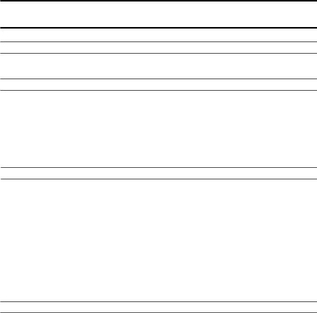
Figure 1: RMA-560 Dual Purge Robot Mounted Rotary Atomizer– Direct Charge. With and without Repulsion Ring.
GENERAL DESCRIPTION
BellCupAssembly
Bell cups are made of high strength Titanium, Aluminum or High Wear Coated Aluminum. Serrated cups are available in 30mm, 55mm and 65 mm. Non-serrated are available in 55mm and 65mm.
See ordering matrix for exact size and material combination availability.
AirBearingTurbineAssembly
The air bearing turbine assembly with bell cup is mounted to the air manifold assembly with a turbine retaining ring.
Air Manifold Assembly
The atomizer extension is angled at 60˚ for robot applications. The fluid feed tube and fiber optic turbine speed emitter are threaded into the front of the manifold. The turbine, fluid, and air manifolds areseparatedfromthebellplateassemblybyfive support rods. Nested between the manifolds and the bell plate is the high voltage cascade.
Bell Plate Assembly
The bell plate assembly is designed to be at ground potential when mounted to the robot plate component within the tubing bundle assembly.
The air and fluid ports are compactly oriented for use in robotic applications. The air supplies are ported through the five support rods directly to the air manifold assembly. On the exterior side of the bell plate, the ports are provided with O-ring seals so that the atomizer can be quickly mated and secured to the robot plate.
Robot Plate
The robot plate is a component of the tubing bundle assemblyandintendedtobepermanentlymounted to the robot. Awrist adapter is also available, which matches the robot’s mounting configuration. The incoming air lines, fluid lines, low voltage cable, and fiber optic cable are connected to the fittings provided at the robot plate. The bell plate of the atomizer assembly is secured to the robot plate with a threaded retaining ring.
Valve Manifold
Thismanifoldcanbeconfiguredforeithersingleor dual purge application. The dual purge can allow two colors to be loaded at one time.
Break-Away Feature (Optional)
The RMA-560 is available with or without a breakaway feature. By replacing the five (5) stainless steel screws with five (5) special designed plastic screws (77524-00). This feature minimizes the damage to the atomizer or robot, if a collision occurs, the five (5) plastic break-away screws fail and the atomizer will break free. This will leave the break-away ring and the mounting ring attached to the robot. (The applicator will fall to the booth grate or floor).
Power Supply and Controls
The high voltage cascade is located inside the applicator and is controlled by the MicroPak control unit. The low voltage output of the MicroPak is multiplied by the internal cascade to the high voltage level required. This eliminates the need for a high voltage cable. A low voltage cable interconnects the cascade and MicroPak control. The
MicroPakformatisdesignedtofitinaconventional
19-inch or 10-inch rack and requires a 24V power input at a maximum 3 amps. The MicroPak and the internal cascade will produce voltages up to 100,000 VDC.
The MicroPak is designed to electronically limit current to provide safe operation in a spray booth. The voltage and current draw of the atomizer are continuously displayed on the MicroPak control panel. Voltage and over-current limits are adjustable on the front of the MicroPak. MicroPak
7 |
LN-9278-13 |
RMA-560 Single/Dual Purge Direct Charge - Introduction
internal safety circuits will shut down the system on over-current and cable faults.
With additional control modules, all of the functions of the RMA-560 and MicroPak can be controlled by a programmable controller. A Serial Atomizer Module pneumatically controls the speed of the rotary atomizer with dynamic feedback through a fiber optic transmitter located on the applicator. A
Serial Digital Module pneumatically controls the paint, solvent, and dump valves located on the atomizer. An I/O module provides communication between these modules and the PLC.
The above modules are mounted in one 19-inch rack and interconnected through a common mother board.
Ransburg
8 |
LN-9278-13 |

RMA-560 Single/Dual Purge Direct Charge - Introduction |
Ransburg |
SPECIFICATIONS
Electrical:
Power Supply Type: |
MicroPak |
Charging Method: |
Direct |
Output Voltage: |
30-100 kV Variable |
|
(100 kV Maximum) |
Output Current: |
125 µA |
Turbine Speed |
Atomizer Module |
Control: |
|
Part Spray Ability: |
Determine spray ability of |
|
part to be coated using |
|
Test Equipment (76652) |
|
(Paint Conductivity Meter) |
|
|
Mechanical:
Length: (See RMA-560 Tool Point, Center of Gravity, and Envelope Dimension
(Single and Dual Flex) figure in the “Introduction” section.)
Diameter: (See RMA-560 Tool Point, Center of Gravity, and Envelope Dimensions
(Single and Dual Flex) figure in the “Introduction” section.)
Approximate Weight (Dual Flex)
Atomizer Only: 12.77 lbs. (5.8 Kg) max.
Total Payload with Robot Plate (Dual Flex) & Adapter: 15.57 lbs. (7.1 Kg) max.
Turbine Type: |
Air Bearing Impulse Drive |
Turbine Air Supply: |
Variable (See “Pressure |
|
Flow Data Charts” in the |
Maximum/Minimum |
“Introduction” section.) |
|
|
Turbine Speed: |
Continuous80Krpmmax. |
|
/20K rpm min. See excep- |
Maximum Angular |
tion at “Fluid Flow Rate” |
|
|
Velocity for Turbine |
250°/sec. |
(Robot Motion): |
|
Tubing Bundle |
|
Max. Rotation: |
450° in Either Direction |
Bearing Air Supply |
|
at the Applicator: |
90 psig (±10 psi) |
(Nominal): |
(621 kPa ±69 kPa) 2.9 |
|
SCFM (82 slpm) |
Mechanical (Cont.):
Shaping Air #1 |
Variable (See “Pressure |
(SAI) Supply: |
Flow Data Charts” in the |
|
“Introduction” section) |
Shaping Air #2 |
Variable (See “Pressure |
(SAO) Supply: |
Flow Data Charts” in the |
|
“Introduction” section) |
Brake Air Supply |
60-100 psig (414-689 kPa) |
(Nominal): |
|
Maximum Fluid Pressure Supply: |
|
Paint: |
200 psi (1379 kPa) |
Solvent: |
150 psi (1035 kPa) |
Fluid Flow Rate: |
25-800 cc/min. |
30mm Bell Cup |
(See exclusion below) |
Max. Flow Rate: 300 cc/ |
|
55mm Bell Cup |
min. at 80,000 rpm |
Max Flow Rate: 500 cc/ |
|
|
min. at 80,000 rpm |
|
Max. Flow Rate: 800 cc/ |
65mm Bell Cup |
min at 70,000 rpm |
Max. Flow Rate: 500 cc/ |
|
|
min at 80,000 rpm |
|
Max. Flow Rate: 800 cc/ |
|
min. at 70,000 rpm |
Bell Cup Cleaning Time (Internal/External): 2.7 sec. (approx.)
Color Change Time: Dependent on system
configuration, fluid pressures, fluid viscosity,fluid line lengths, etc.
Speed Readout: Magnetic pick-up, unidirectional fiber optic transmission
Atomizer
Replacement Time: Less than 5 min.
Bell Cup
Replacement Time: Less than 2 min.
Minimum Control Equipment Requirements: (Versions listed or higher)
MicroPak |
LECU5004-11 (V.3.84) |
Atomizer Module |
A11925-00 (V.0.4) |
I/O Module |
A11435-00 (V.1.4) |
|
(0.01V) (4-20 mA) |
* Specifications and ratings based on testing at sea level standard conditions.
Air Heater Recommendation:
An Air Heater is recommended for the turbine air supply. See Air Heater and filteration recommendation later in this manual
9 |
LN-9278-13 |
RMA-560 Single/Dual Purge Direct Charge - Introduction |
Ransburg |
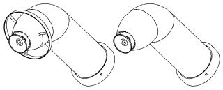
IMPORTANT NUMBERS
Record these numbers in a log book for future reference. The last digits of the Atomizer serial number are also the Turbine serial numbers.
Turbine Serial Number |
Atomizer Serial Number |
||
|
|
|
|
|
|
|
|
(cup only, not with splash plate)
10 |
LN-9278-13 |

RMA-560 Single/Dual Purge Direct Charge - Introduction |
Ransburg |
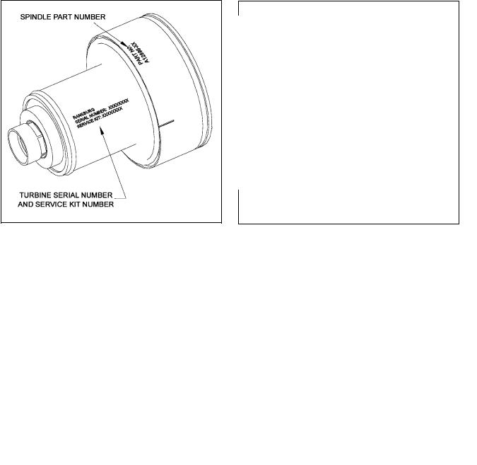
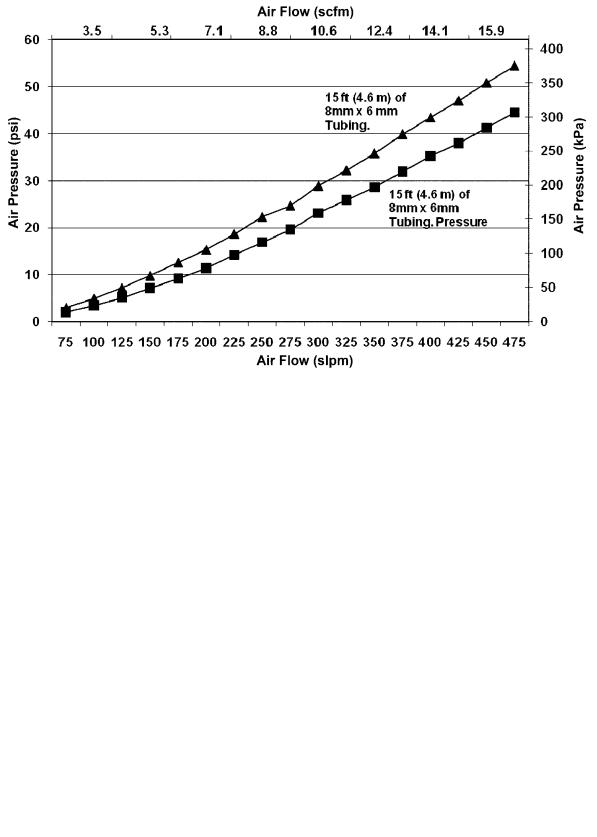
GRAPHS
Graphical information provided for reference only for all charts. Unless otherwise specified, all pressure data shown was measured 12-inches (305mm) behind the applicator.
TURBINE SPEED VS. PRESSURE - NO LOAD
11 |
LN-9278-13 |

RMA-560 Single/Dual Purge Direct Charge - Introduction |
Ransburg |
12 |
LN-9278-13 |
RMA-560 Single/Dual Purge Direct Charge - Introduction |
Ransburg |
BEARING AIR FLOW RATE VS. SUPPLY PRESSURE
13 |
LN-9278-13 |
RMA-560 Single/Dual Purge Direct Charge - Introduction |
Ransburg |
FLOW VS. PRESSURE
MONO FLEX SHAPE AIR - SINGLE SUPPLY SOURCE
A12874-05/-06/-07 SHAPING AIR KIT
FLOW VS. PRESSURE
MONO FLEX SHAPE AIR - DUAL SUPPLY SOURCE
A12874-05/-06/-07 SHAPING AIR KIT
14 |
LN-9278-13 |
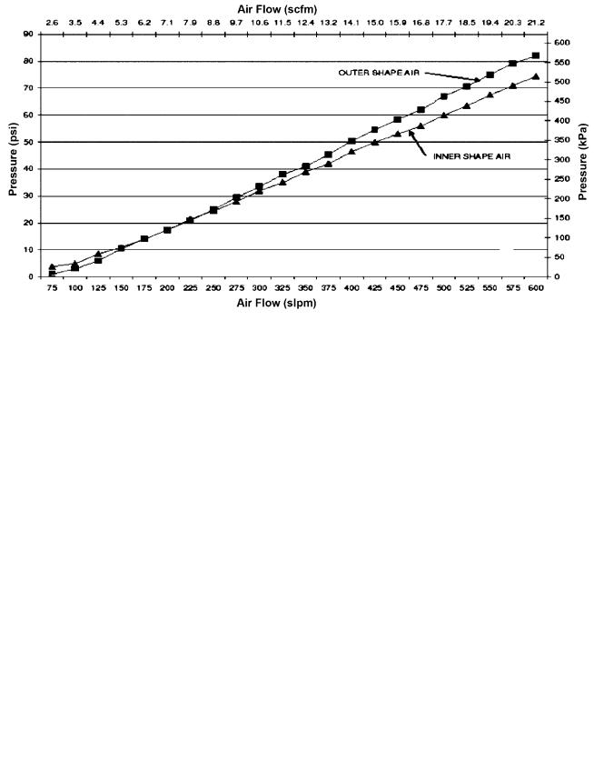
RMA-560 Single/Dual Purge Direct Charge - Introduction
RMA-560 DUAL FLEX AIR
A12874-08/-09/-10 SERIES SHAPE AIR
FLOW VS. PRESSURE
SHAPING AIR FLOW VS. SUPPLY PRESSURE 30MM GHOST BUSTER SHROUD STYLE A12874-03/04 SHAPING AIR KIT
Ransburg
15 |
LN-9278-13 |
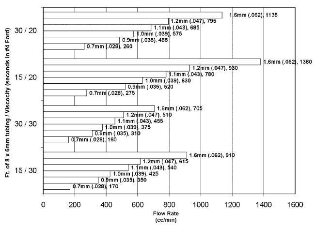
RMA-560 Single/Dual Purge Direct Charge - Introduction
MAXIMUM FLOW RATE BY TIP SIZE,
HOSE LENGTH, AND MATERIAL VISCOSITY
Ransburg
16 |
|
|
|
|
|
|
|
|
|
|
|
|
|
|
|
|
|
|
|
|
|
LN-9278-13 |
|
|
|
|
|
|
|
|
|
|
|
|
|
|
|
|
|
|
|
|
|
||
|
|
|
|
|
|
|
|
|
|
|
|
|
|
|
|
|
|
|
|
|
||
|
|
|
|
|
|
|
|
|
|
|
|
|
|
|
|
|
|
|
|
|
||
|
|
|
|
|
|
|
|
|
|
|
|
|
|
|
|
|
|
|
|
|
||
|
|
|
|
|
|
|
|
|
|
|
|
|
|
|
|
|
|
|
|
|
||
|
|
|
|
|
|
|
|
|
|
|
|
|
|
|
|
|
|
|
|
|
||
|
|
|
|
|
|
|
|
|
|
|
|
|
|
|
|
|
|
|
|
|
||
|
|
|
|
|
|
|
|
|
|
|
|
|
|
|
|
|
|
|
|
|
||
|
|
|
|
|
|
|
|
|
|
|
|
|
|
|
|
|
|
|
|
|
||
|
|
|
|
|
|
|
|
|
|
|
|
|
|
|
|
|
|
|
|
|
||
|
|
|
|
|
|
|
|
|
|
|
|
|
|
|
|
|
|
|
|
|
||
|
|
|
|
|
|
|
|
|
|
|
|
|
|
|
|
|
|
|
|
|
||
|
|
|
|
|
|
|
|
|
|
|
|
|
|
|
|
|
|
|
|
|
||
|
|
|
|
|
|
|
|
|
|
|
|
|
|
|
|
|
|
|
|
|
||
|
|
|
|
|
|
|
|
|
|
|
|
|
|
|
|
|
|
|
|
|
||
|
|
|
|
|
|
|
|
|
|
|
|
|
|
|
|
|
|
|
|
|
||
|
|
|
|
|
|
|
|
|
|
|
|
|
|
|
|
|
|
|
|
|
||
|
|
|
|
|
|
|
|
|
|
|
|
|
|
|
|
|
|
|
|
|
||
|
|
|
|
|
|
|
|
|
|
|
|
|
|
|
|
|
|
|
|
|
||
|
|
|
|
|
|
|
|
|
|
|
|
|
|
|
|
|
|
|
|
|
||
|
|
|
|
|
|
|
|
|
|
|
|
|
|
|
|
|
|
|
|
|
||
|
|
|
|
|
|
|
|
|
|
|
|
|
|
|
|
|
|
|
|
|
||
|
|
|
|
|
|
|
|
|
|
|
|
|
|
|
|
|
|
|
|
|
||
|
|
|
|
|
|
|
|
|
|
|
|
|
|
|
|
|
|
|
|
|
||
|
|
|
|
|
|
|
|
|
|
|
|
|
|
|
|
|
|
|
|
|
||
|
|
|
|
|
|
|
|
|
|
|
|
|
|
|
|
|
|
|
|
|
||
|
|
|
|
|
|
|
|
|
|
|
|
|
|
|
|
|
|
|
|
|
RMA-560 Single/Dual Purge Direct Charge - Introduction |
Ransburg |
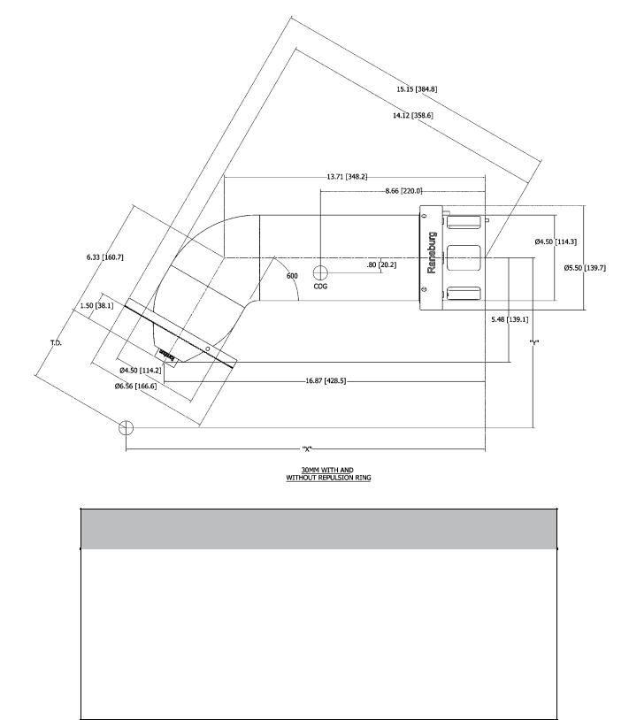
RMA-560 TOOL CENTER POINT DIMENSIONS (30mm)
30MM WITH AND WITHOUT REPULSION RING
TD |
X |
Y |
|
|
|
6-Inches (152mm) |
19.87-Inches (504.7mm) |
10.67-Inches (271.3mm) |
|
|
|
8-Inches (203mm) |
20.87-Inches (530.1mm) |
12.41-Inches (315.2mm) |
10-Inches (254mm) |
21.87-Inches (555.5mm) |
14.14-Inches (359.2mm) |
12-Inches (305mm) |
22.87-Inches (580.9mm) |
15.87-Inches (403.1 mm) |
Weight:
With Repulsion Ring 13.99 lbs. (6.35 Kg)
Without Repulsion Ring 14.99 lbs. (6.44 Kg)
17 |
LN-9278-13 |
RMA-560 Single/Dual Purge Direct Charge - Introduction |
Ransburg |
RMA-560 TOOL CENTER POINT DIMENSIONS (55mm)
55MM DUAL FLEX WITH AND WITHOUT REPULSION RING
TD |
X |
Y |
|
|
|
6-Inches (152mm) |
19.79-Inches (502.7mm) |
10.53-Inches (267.5mm) |
|
|
|
8-Inches (203mm) |
20.79-Inches (528.1mm) |
12.26-Inches (311.4mm) |
|
|
|
10-Inches (254mm) |
21.79-Inches (553.5mm) |
13.99-Inches (355.3mm) |
12-Inches (305mm) |
22.79-Inches (578.9mm) |
15.72-Inches (399.3mm) |
|
|
|
Weight: |
|
|
13.88 lbs. (6.3 Kg) |
|
|
18 |
LN-9278-13 |

RMA-560 Single/Dual Purge Direct Charge - Introduction |
Ransburg |
RMA-560 TOOL CENTER POINT DIMENSIONS (65mm Mono Flex)
65MM MONO FLEX WITH AND WITHOUT REPULSION RING
TD |
X |
Y |
|
|
|
6-Inches (152mm) |
19.83-Inches (503.6mm) |
10.61-Inches (269.5mm) |
|
|
|
8-Inches (203mm) |
20.83-Inches (529mm) |
12.34-Inches (313.4mm) |
10-Inches (254mm) |
21.83-Inches (554.4mm) |
14.07-Inches (357.4mm) |
12-Inches (305mm) |
22.83-Inches (579.8mm) |
15.80-Inches (401.3mm) |
Weight:
With Repulsion Ring 14.3 lbs. (6.49 Kg)
Without Repulsion Ring 14.1 lbs. (6.40 Kg)
19 |
LN-9278-13 |
RMA-560 Single/Dual Purge Direct Charge - Introduction |
Ransburg |
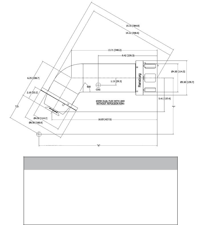
RMA-560 TOOL CENTER POINT DIMENSIONS (65mm Dual Flex)
65MM DUAL FLEX WITH AND WITHOUT REPULSION RING
TD |
X |
Y |
|
|
|
6-Inches (152mm) |
19.83-Inches (503.6mm) |
10.61-Inches (269.4mm) |
|
|
|
8-Inches (203mm) |
20.83-Inches (529mm) |
12.34-Inches (313.4mm) |
10-Inches (254mm) |
21.83-Inches (554.4mm) |
14.07-Inches (357.4mm) |
12-Inches (305mm) |
22.83-Inches (579.8mm) |
15.80-Inches (401.4mm) |
Weight:
With Repulsion Ring 15.57 lbs. (7.1 Kg)
Without Repulsion Ring 15.37 lbs. (6.97 Kg)
20 |
LN-9278-13 |

RMA-560 Single/Dual Purge Direct Charge - Introduction
CIRCUIT SCHEMATIC
Ransburg
21 |
LN-9278-13 |

RMA-560 Single/Dual Purge Direct Charge - Introduction
VALVE SCHEMATIC
Ransburg
22 |
LN-9278-13 |

RMA-560 Single/Dual Purge Direct Charge - Installation |
Ransburg |
INSTALLATION
AIR FILTER INSTALLATION
(GENERAL GUIDELINES)
The following air filter installation guidelines are essential for optimum performance:
1.Use 25mm OD (1-Inch OD) minimum inbound main air line.
2.Useonlyrecommendedpre-filtersandbearing air filters as shown in “Air filtration Requirements” chart in the ”Installation” section. Additional system air filtration (i.e., refrigerated air dryer) may also be used if desired.
3.Mount all the air filters as close as possible to the RMA-560 applicator. (DO NOT mount further than 30-Feet (9.1 meters) away.)
4.DO NOT use tape, pipe dope, or other thread sealant downstream of the bearing air filter. Looseflakesoftapeorothersealantcanbreak loose and plug the very fine air holes in the turbine air bearings.
5.Air heaters are highly recommended for use in thesystemtominimizetheeffectofexcessively humid conditions and maintain turbine load capabilities. Iftheheatedairwillexceed120°F (48.9°C), the heater must be located after all filters to prevent damage to the filter media.
NOTE
Each applicator must have its own filter for bearing air. Recommended: RPM-418 or equivalent.
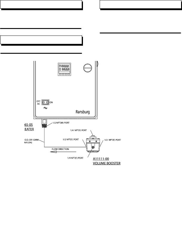
With the exception of fluid, dump, and bearing air, all other pilot and air supply lines should be bulk-headed and their diameters increased one size. Forexample: Turbineairshouldbeincreased to 12mm OD from bulkhead plate to the volume booster or heater outlet.
Volume Booster Recommendation (Turbine Air): (For use with A11065-05 Air Heater or Non-Air Heater System)
Ransburg Part # A11111-00
•• Pilot Operated Regulator Non-Bleed Pilot
•• SCFM-200
•• Supply - 300 P.S.I.
•• Temperature Range: 40˚ - 120° F
TUBE SIZE AIR PRESSURE REQUIREMENTS
|
|
Tube Size |
Air Pressure Requirements |
|
|
|
|
Bearing Air Supply (BA/PT) |
8 |
X 6 mm (Natural) |
(90 psi +/- 10 kPa) (621 +/- 69 kPa) |
Bearing Air Return (BA RTN) |
4mm (5/32”) (Yellow) |
90 psi +/- 10 at atomizer card (552 +/- 138 kPa) |
|
Turbine Air (T.A.) |
10 X 8mm (Green) |
Variable |
|
Outer Air (SAO/FA) |
8 |
X 6mm (Gray |
Variable |
Pattern Control Air #1 (SAI/AA) |
8 |
X 6mm (Blue) |
Variable |
Brake Air (BRK) (if used) |
8 |
X 6 mm (Natural) |
60-100 psi (414-689 kPa) |
Paint Valve #1 (P1T) |
4mm OD (5/32”) (Natural) |
80 psi +/- 10 (552 +/- 70 kPa) |
|
|
|
|
|
Dump Valve #1 Control (P1D) |
4mm OD (5/32”) (Gray) |
80 psi +/- 10 (352 +/- 70 kPa) |
|
Solvent Valve Control (ST/RP) |
4mm OD (5/32”) (Blue) |
80-100 psi (552-873 kPa) |
|
|
|
|
|
Paint Valve #2 (P2T) |
4mm (5/32”) (Natural) |
(552 +/- 70 kPa) |
|
Dump Valve #2 Control (P2D) |
4mm (5/32”) (Black) |
80 psi +/- 70 kPa) |
|
|
|
|
|
23 |
LN-9278-13 |

RMA-560 Single/Dual Purge Direct Charge - Installation |
Ransburg |
EQUIPMENT GROUNDING / SAFETY RECOMMENDATIONS
In electrostatic coating systems, the flow of high voltage power from the power supply to the atomizer is insulated from ground and isolated from all other functions equipment. When the voltage reaches the atomizer, it is transferred to the coating material where, by introducing a negative charge, it causes the atomized fluid to seek the nearest positive ground. In a properly constructed and operated system, that ground will be the target object.
The directed conduction of the electric charge, through its array of wires, cables, and equipment, is accompanied by a variety of stray electrical charges passing through the air by various means such as: air ionization, charged particles in the air and radiated energy. Such charges may be attracted to any conductive material in the spray area. If the conductive material does not provide a safe drain to electrical ground, which will allow the charge to dissipate as fast as it accumulates, it may store the charge. When its electrical storage limit is reached, or when it is breached by external circumstances (such as the approach of a grounded object or person, or one at lower potential), it may discharge its stored charge to the nearest ground. If there is no safe path to ground (such as a ground wire or braided cable) it may discharge through the air as a spark. A spark may ignite the flammable atmosphere of a spray area. The hazard area extends from the point of origin up to as much as a twenty-foot radius.
(See the NFPA-33 for definition and limitations of a hazard area.)
It is simple, but vital matter to be sure that all conductive objects within the spray area are grounded. All cabinets, housing, bases, supports, and stands, which are not by design, insulated from ground, be connected directly and INDIVIDUALLY to earth ground. Resting on a concrete floor or being attached to a building column may not always be sufficient ground.
In order to provide the best ground connection possible, always attach a ground wire or insulated braided cable the terminal indicated by the ground
symbol and then to a proven ground. Always check ground connections for integrity. Some items, such as rotators and paint stands, may be supported on an insulator, but all components of the system up to the insulator MUST be grounded.
NOTE
Ransburg recommends that ground connections to earth ground be 3/4” insulated copper braided wire. Grounds between assemblies within a machine should be run to a central point within the machine using #18 insulated stranded copper wire minimum. All connections should be mechanically sound and have less than 5 ohms of resistance between assemblies and the common point. The resistance between the central point and earth ground should be less than 5 ohms as well.
Where items are mounted directly on structural components such as building columns, the ground connection MUST still be made. In many cases the structural component may be painted or coated with an insulated material and in all cases, the equipment will provide the necessary connection at one end, but the user must be sure that the other end is secured to an earth ground. This may be achieved by the use of a standard ground clamp (properly secured), by brazing or by piercing the structural component enough to assure connection. All ground connections should be made to the most conductive metallic structural ground available.
To be sure that everything is properly grounded, the following steps should be undertaken at least daily:
1.Inspect all ground wires. Look for good, firm joints at all points of connection. Look for breaks in the ground wire. Repair all defects IMMEDIATELY!
2.Inspect the floor or grates for excessive accumulation of dried coating material or other residue. If there is any, remove it!
24 |
LN-9278-13 |
RMA-560 Single/Dual Purge Direct Charge - Installation |
Ransburg |
SAFE GROUNDING IS A MATTER OF PROPER EQUIPMENT MAINTENANCE AND INSTALLATION, CORRECT OPERATION AND GOOD HOUSEKEEPING. Daily inspection of grounding apparatus and conditions, however, will help prevent hazards that are cause by normal operations.
BE SURE THAT:
1.All objects in the spray area are grounded.
2.Personnel in the spray area are properly grounded. (Conductive safety shoes and coveralls.)
3.That the target object is properly grounded (less than 1 megohm resistance).
4.That the high voltage is off except during normal application.
5.That the high voltage is off and applicators are grounded during maintenance operations.
6.The spray area is kept free of accumulated coating deposits.
7.All combustible liquids in the spray area (outside of automatic delivery systems) are kept to minimum and are kept in fire safe, grounded containers. (See NFPA-30 and chapter 6 of NFPA-33.)
8.Proper ventilation is provided.
9.Personnel must thoroughly understand the equipment, its operation and maintenance, and all safety precautions.
AIR HEATER REQUIREMENTS
Turbine drive air expands as it moves through the turbinewheelcavityandasitexitstheturbinefrom the exhaust port. This expansion will cause cooling of the exhaust air and the surfaces it contacts. Thissameexpansioncoolingcanoccuracrossthe shapingairexitports. Thiscoolingaffectcancause surface temperatures to fall below the dew point of the booth, which will result in condensation on the interior and exterior of the atomizer, machine,
and its components. It is even possible that the temperature of the supply air may be below the booth dew point, even without additional expansion cooling.
Condensation is especially probable in waterborne applications when booth temperature and relative humidity levels are typically maintained very high.
Thiscondensationwillallowsufficientconductivity of the surfaces such that they act as an erratic ground source potential. This can cause damage to the equipment.
It is therefore, a requirement that turbine exhaust air temperature be maintained above the booth dew point to prevent condensation from forming on atomizer surfaces. Doing so will eliminate moisture as a potential defect in painted surfaces as well as extending equipment life. Thus, it is recommended that air heaters be installed into the atomizer air supply lines, i.e. turbine drive air, shaping air, and seal air. The air heaters must be of sufficient capacity, capable of raising the incoming air temperature at least 40°F (4.4°C) at a flow rate of 60 SCFM per applicator.
The actual air heater process setting depends on applicator fluid flow rate load, booth conditions, turbineairflowsettings,andincomingairtemperature. The heater should be set as low as possible, sufficient to maintain the applicator surface temperatures above the dew point in the booth.
Example: With the incoming air temperature at 72°F (22.2°C), and RMA-560 with 65mm bell cup rotating unloaded at 60 krpm has a turbine outlet temperature drop of approximately 28°F (-2.2°C) @ 40 krpm unloaded, ∆~14°F (-10°C). Referring totheASHRAEPsychrometricchart,thesaturation temperature range (dew point) of a spray booth maintained at 70-75°F/65-70% RH is 62-68°F (21.1-23.9°C/65-70°RH is 16.7-20°C). Thus it is almost certain that the surface temperatures of the applicator will fall below the dew point of the booth, and an air heater will be needed in this case.
To prevent condensation, a Ransburg air heater assemblyshouldbeassembledaftertheairfilters and volume booster. (See heater and filtration options later in this manual).
25 |
LN-9278-13 |
RMA-560 Single/Dual Purge Direct Charge - Installation |
Ransburg |
AIR HEATER AND FILTRATION OPTIONS
NOTE
Failure to use an air heater may cause damage to equipment or ruin the finished component being processed.
NOTE
Connect air heater to turbine air tubing.
NOTE
If using the A11065-05 Air Heater, air filters equivelant to HAF-503, HAF-508 and RPM-418 must be used. (See descriptions in this manual).
A11065-05 Air Heater
26 |
LN-9278-13 |

RMA-560 Single/Dual Purge Direct Charge - Installation |
Ransburg |
A13230-XX AIR HEATER AND FILTER COMBINATION
This combination includes filtration for turbine as well as bearing air.
FILTER & HEATER ASSEMBLY A13230-XX
DashNo. |
Description |
“A” |
“B” |
“C” |
“D” |
|
|
|
|
|
|
A13230-01 |
115 V.@ 13A METRIC FITTINGS |
A13434-01 |
A13426-00 |
A13429-00 |
A13433-00 |
A13230-02 |
230 V.@ 6.5A METRIC FITTINGS |
A13434-02 |
A13426-00 |
A13429-00 |
A13433-00 |
A13230-03 |
115 V.@ 13A FRACTIONAL FITTINGS |
A13434-01 |
SSP-6439 |
A13428-00 |
A13433-00 |
A13230-04 |
230 V.@6.5A FRACTIONAL FITTINGS |
A13434-02 |
SSP-6439 |
A13428-00 |
A13433-00 |
A13230-XX AIR HEATER AND FILTER COMBINATION
Item |
Part # |
Description |
Qty. |
|
|
|
|
|
|
1 |
“A” |
AIR BLOCK, NIPPLES & AIR HEATER |
1 |
|
2 |
A13427-00 |
INLET FITTING, 3/8 NPS(M) X 1/2 NPT(M) |
1 |
|
3 |
“B” |
BEARING AIR FEED, SWIVEL ELBOW 1/4 O.D.TUBE X 1/4 NPT(M) |
1 |
|
BEARING AIR FEED, 6mm O.D. TUBE X 1/4 NPT(M) STRAIGHT ADAPTER |
||||
|
|
|
||
4 |
79253-02 |
AIR FITTING, SWIVEL ELBOW 5/32 O.D. TUBE X 1/4 NPT(M) |
2 |
|
5 |
“C” |
OUTLET FITTING, 1/2 O.D. TUBE X 1/2 NPT(M) STAINLESS STEEL |
1 |
|
OUTLET FITTING, 12mm O.D. TUBE X 1/2 NPT(M) STAINLESS STEEL |
||||
|
|
|
||
6 |
A11111-00 |
VOLUME BOOSTER |
1 |
|
7 |
“D” |
AIR FILTER & NIPPLE INCLUDED |
1 |
|
8 |
SI-13-07 |
A13230-XX SERVICE LITERATURE (PROVIDED BY OTHER) |
REF. |
ALL UNITS: REPLACEMENT PARTS: (SERVICE NOTE)
HEATING ELEMENT USE: A13432-01 FOR A13230-01 AND A13230-03 (115V UNITS) A13432-02 FOR A13230-02 AND A13230-04 (230V UNITS)
AIR FILTER ELEMENT USE A13232-00 THERMOMETER USE A13431-00
27 |
LN-9278-13 |
Loading...