

Page 1
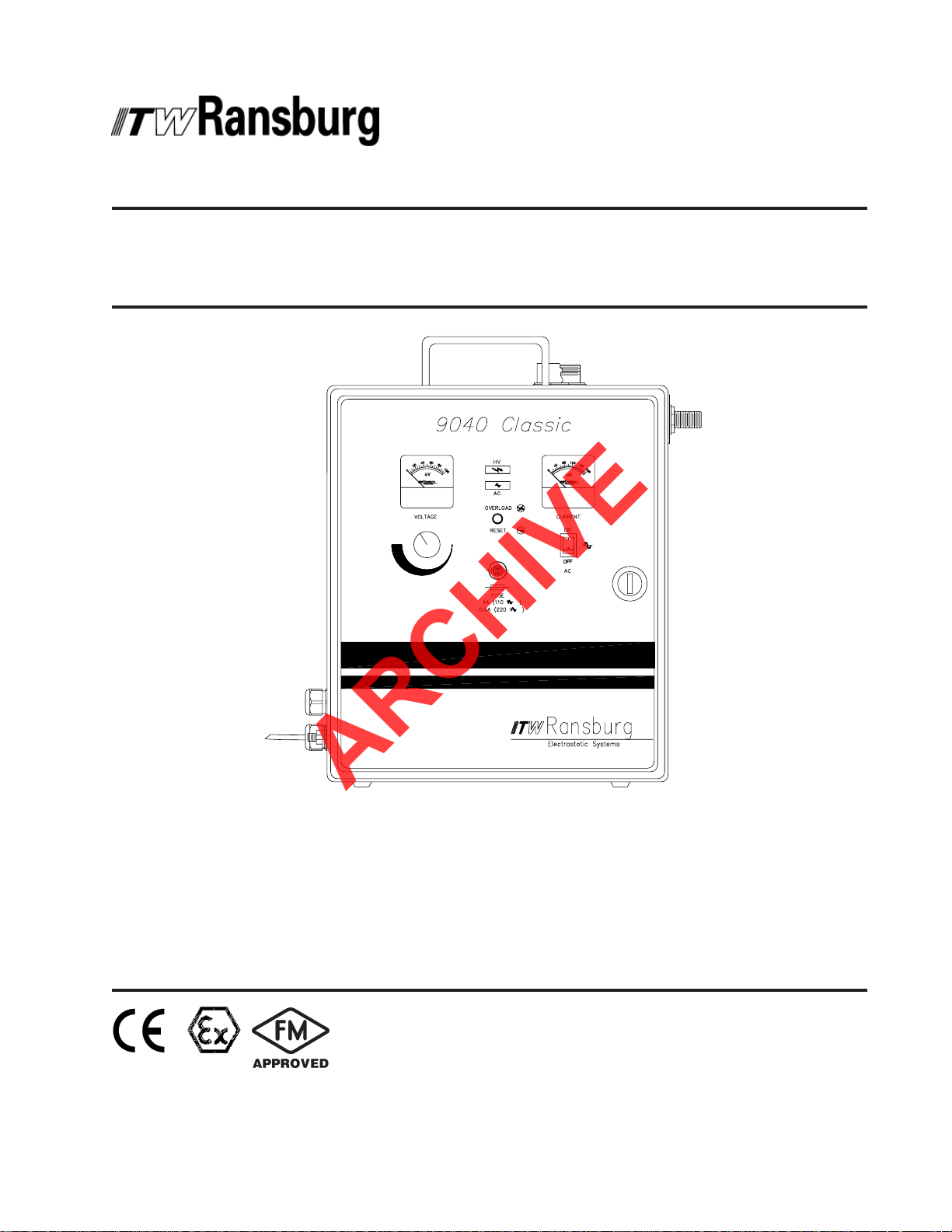
SERVICE MANUAL
ARCHIVE
CP-97-02.5CP-97-02.5
CP-97-02.5
CP-97-02.5CP-97-02.5
(Replaces CP-97-02.4)
May - 2008
9040 CLASSIC HIGH VOL9040 CLASSIC HIGH VOL
9040 CLASSIC HIGH VOL
9040 CLASSIC HIGH VOL9040 CLASSIC HIGH VOL
(for the REA(for the REA
(for the REA
(for the REA(for the REA
TM TM
TM
TM TM
& M90& M90
& M90
& M90& M90
TMTM
TM
TMTM
Classic Coating Systems) Classic Coating Systems)
Classic Coating Systems)
Classic Coating Systems) Classic Coating Systems)
TT
AGE POWER SUPPLAGE POWER SUPPL
T
AGE POWER SUPPL
TT
AGE POWER SUPPLAGE POWER SUPPL
YY
Y
YY
MODEL:MODEL:
MODEL:
MODEL:MODEL:
76447-10X / REA-IV APPLICA76447-10X / REA-IV APPLICA
76447-10X / REA-IV APPLICA
76447-10X / REA-IV APPLICA76447-10X / REA-IV APPLICA
76447-12X / REA-III APPLICA76447-12X / REA-III APPLICA
76447-12X / REA-III APPLICA
76447-12X / REA-III APPLICA76447-12X / REA-III APPLICA
76447-13X / REA-III AUT76447-13X / REA-III AUT
76447-13X / REA-III AUT
76447-13X / REA-III AUT76447-13X / REA-III AUT
76447-14X / M90 CLASSIC APPLICA76447-14X / M90 CLASSIC APPLICA
76447-14X / M90 CLASSIC APPLICA
76447-14X / M90 CLASSIC APPLICA76447-14X / M90 CLASSIC APPLICA
OMAOMA
OMA
OMAOMA
IMPORIMPOR
IMPOR
IMPORIMPOR
carefully read SAFETY PRECAUTIONS,carefully read SAFETY PRECAUTIONS,
carefully read SAFETY PRECAUTIONS,
carefully read SAFETY PRECAUTIONS,carefully read SAFETY PRECAUTIONS,
starting on page 1, and all instructions instarting on page 1, and all instructions in
starting on page 1, and all instructions in
starting on page 1, and all instructions instarting on page 1, and all instructions in
this manual. Keep this Service Manual forthis manual. Keep this Service Manual for
this manual. Keep this Service Manual for
this manual. Keep this Service Manual forthis manual. Keep this Service Manual for
future reference.future reference.
future reference.
future reference.future reference.
TT
OROR
T
OR
TT
OROR
TT
OROR
T
OR
TT
OROR
TICTIC
TIC
TICTIC
TT
ANTANT
T
ANT
TT
ANTANT
TT
OROR
T
OR
TT
OROR
: Before using this equipment,: Before using this equipment,
: Before using this equipment,
: Before using this equipment,: Before using this equipment,
Service Manual Price:Service Manual Price:
Service Manual Price: €
Service Manual Price:Service Manual Price:
25.00 (Euro)25.00 (Euro)
25.00 (Euro)
25.00 (Euro)25.00 (Euro)
$30.00 (U.S.)$30.00 (U.S.)
$30.00 (U.S.)
$30.00 (U.S.)$30.00 (U.S.)
Page 2

NOTE:NOTE:
ARCHIVE
NOTE: This manual has been changed from revision
NOTE:NOTE:
Reasons for this change are noted under “Manual Change Summary” inside the back
cover of this manual.
CP-97-02.4CP-97-02.4
CP-97-02.4 to revision
CP-97-02.4CP-97-02.4
CP-97-02.5 CP-97-02.5
CP-97-02.5.
CP-97-02.5 CP-97-02.5
CP-97-02.5
Page 3
CONTENTSCONTENTS
ARCHIVE
CONTENTS
CONTENTSCONTENTS
SAFETY:SAFETY:
SAFETY:
SAFETY:SAFETY:
9040 Classic for REA & M90 Systems - Contents
PAGEPAGE
PAGE
PAGEPAGE
1-61-6
1-6
1-61-6
SAFETY PRECAUTIONS...........................................................................................................
HAZARDS / SAFEGUARDS.......................................................................................................
ATEXATEX
ATEX
ATEXATEX
EUROPEAN ATEX DIRECTIVE.................................................................................................
EUROPEAN ATEX LABELS.......................................................................................................
INTRODUCTION:INTRODUCTION:
INTRODUCTION:
INTRODUCTION:INTRODUCTION:
GENERAL DESCRIPTION.........................................................................................................
SPECIFICATIONS......................................................................................................................
9040 CLASSIC FOR REA / M90 FEATURES............................................................................
INSTALLATION:INSTALLATION:
INSTALLATION:
INSTALLATION:INSTALLATION:
LOCATION..................................................................................................................................
INPUT VOLTAGE SELECTION.................................................................................................
INPUT CONNECTIONS.............................................................................................................
EXTERNAL CONNECTIONS.....................................................................................................
TYPICAL REA AND M90 APPLICATOR INSTALLATIONS......................................................
OPERATION:OPERATION:
OPERATION:
OPERATION:OPERATION:
1
2-5
7-87-8
7-8
7-87-8
7
8
9-119-11
9-11
9-119-11
9-10
10
11
12-1612-16
12-16
12-1612-16
12
12
13
13-15
16
17-2017-20
17-20
17-2017-20
OPERATING CONTROLS.........................................................................................................
THEORY OF OPERATION........................................................................................................
OPERATING PROCEDURES....................................................................................................
MAINTENANCE:MAINTENANCE:
MAINTENANCE:
MAINTENANCE:MAINTENANCE:
ROUTINE PREVENTIVE MAINTENANCE................................................................................
TROUBLESHOOTING................................................................................................................
SERVICE LEVEL.........................................................................................................................
REPLACEMENT PROCEDURES..............................................................................................
TROUBLESHOOTING GUIDE...................................................................................................
TROUBLESHOOTING DIAGRAM.............................................................................................
9040 CLASSIC POWER SUPPLY BLOCK DIAGRAM.............................................................
PARTS IDENTIFICATION:PARTS IDENTIFICATION:
PARTS IDENTIFICATION:
PARTS IDENTIFICATION:PARTS IDENTIFICATION:
9040 CLASSIC FOR REA AND M90 PARTS DIAGRAM / PARTS LIST.................................
RECOMMENDED SPARE PARTS............................................................................................
ACCESSORIES..........................................................................................................................
WARRANTY POLICIES:WARRANTY POLICIES:
WARRANTY POLICIES:
WARRANTY POLICIES:WARRANTY POLICIES:
LIMITED WARRANTY.................................................................................................................
17
18
18-19
21-3421-34
21-34
21-3421-34
21
21-24
24
25-29
30-31
32
33
35-3835-38
35-38
35-3835-38
35-36
37
37
3939
39
3939
39
CP-97-02.5
Page 4
9040 Classic for REA & M90 Systems - Safety
ARCHIVE
SAFETYSAFETY
SAFETY
SAFETYSAFETY
SAFETY PRECAUTIONSSAFETY PRECAUTIONS
SAFETY PRECAUTIONS
SAFETY PRECAUTIONSSAFETY PRECAUTIONS
W A R N I N GW A R N I N G
W A R N I N G
W A R N I N GW A R N I N G
!!
!
!!
Before operating, maintaining or servicing any
ITW Ransburg coating system, read and
understand all of the technical and safety literature
for your ITW Ransburg products. This manual
contains information that is important for you to
know and understand. This information relates to
USER SAFETY and PREVENTING EQUIPMENT
PROBLEMS. To help you recognize this
information, we use the following symbols. Please
pay particular attention to these sections.
A WARNING! states information to alert youA WARNING! states information to alert you
A WARNING! states information to alert you
A WARNING! states information to alert youA WARNING! states information to alert you
to a situation that might cause serious injuryto a situation that might cause serious injury
to a situation that might cause serious injury
to a situation that might cause serious injuryto a situation that might cause serious injury
if instructions are not followed.if instructions are not followed.
if instructions are not followed.
if instructions are not followed.if instructions are not followed.
A CAUTION! states information that tellsA CAUTION! states information that tells
A CAUTION! states information that tells
A CAUTION! states information that tellsA CAUTION! states information that tells
how to prevent damage to equipment or howhow to prevent damage to equipment or how
how to prevent damage to equipment or how
how to prevent damage to equipment or howhow to prevent damage to equipment or how
to avoid a situation that might cause minorto avoid a situation that might cause minor
to avoid a situation that might cause minor
to avoid a situation that might cause minorto avoid a situation that might cause minor
injury.injury.
injury.
injury.injury.
A NOTE is information relevant to theA NOTE is information relevant to the
A NOTE is information relevant to the
A NOTE is information relevant to theA NOTE is information relevant to the
procedure in progress.procedure in progress.
procedure in progress.
procedure in progress.procedure in progress.
While this manual lists standard specifications
and service procedures, some minor deviations
may be found between this literature and your
equipment. Differences in local codes and plant
requirements, material delivery requirements, etc.,
make such variations inevitable. Compare this
manual with your system installation drawings
and appropriate ITW Ransburg equipment
manuals to reconcile such differences.
> The user
with the Safety Section in this manual and
the ITW Ransburg safety literature therein
identified.
> This manual
oughly understood by
operate, clean or maintain this equipment!
Special care should be taken to ensure that
WARNINGSWARNINGS
the
WARNINGS and safety requirements
WARNINGSWARNINGS
for operating and servicing the equipment
are followed. The user should be aware of
and adhere to
codes and ordinances as well as
SAFETY STANDARD SAFETY STANDARD
SAFETY STANDARD prior to installing,
SAFETY STANDARD SAFETY STANDARD
operating, and/or servicing this equipment.
> The hazards shown on the following
page may occur during the normal use of
this equipment. Please read the hazard
chart beginning on page 2.
MUSTMUST
MUST read and be familiar
MUSTMUST
MUSTMUST
MUST be read and thor-
MUSTMUST
ALLALL
ALL personnel who
ALLALL
ALLALL
ALL local building and fire
ALLALL
W A R N I N GW A R N I N G
W A R N I N G
W A R N I N GW A R N I N G
!!
!
!!
NFPA-33NFPA-33
NFPA-33
NFPA-33NFPA-33
Careful study and continued use of this manual will
provide a better understanding of the equipment
and process, resulting in more efficient operation,
longer trouble-free service and faster, easier
troubleshooting. If you do not have the manuals
and safety literature for your Ransburg system,
contact your local ITW Ransburg representative
or ITW Ransburg.
11
1
11
CP-97-02.5
Page 5
9040 Classic for REA & M90 Systems - Safety
ARCHIVE
AREAAREA
AREA
AREAAREA
Tells where hazards
may occur.
Spray AreaSpray Area
Spray Area
Spray AreaSpray Area
HAZARDHAZARD
HAZARD
HAZARDHAZARD
Tells what the hazard is.
Fire Hazard
Improper or inadequate operation
and maintenance procedures will
cause a fire hazard.
Protection against inadvertent
arcing that is capable of causing
fire or explosion is lost if any safety
interlocks are disabled during
operation. Frequent power supply
shutdown indicates a problem in
the system requiring correction.
SAFEGUARDSSAFEGUARDS
SAFEGUARDS
SAFEGUARDSSAFEGUARDS
Tells how to avoid the hazard.
The 76447 power supply MUST be installed in a
NON-hazardous location in accordance with NFPA-
33.
Fire extinguishing equipment must be present in the
spray area and tested periodically.
Spray areas must be kept clean to prevent the
accumulation of combustible residues.
Smoking must never be allowed in the spray area.
The high voltage supplied to the atomizer must be
turned off prior to cleaning, flushing, or maintenance.
When using solvents for cleaning:
Those used for equipment flushing should have flash
points equal to or higher than those of the coating
material.
Those used for general cleaning must have flash
points above 100
Spray booth ventilation must be kept at the rates
required by NFPA-33, OSHA, and local codes. In
addition, ventilation must be maintained during
cleaning operations using flammable or combustible
solvents.
Electrostatic arcing must be prevented.
Test only in areas free of combustible material.
Testing may require high voltage to be on, but only
as instructed.
Non-factory replacement parts or unauthorized
equipment modifications may cause fire or injury.
If used, the key switch bypass is intended for use
only during setup operations. Production should
never be done with safety interlocks disabled.
Never use equipment intended for use in waterborne
installations to spray solvent based materials.
o
F (37.8oC).
CP-97-02.5
The paint process and equipment should be set up
and operated in accordance with NFPA-33, NEC,
and OSHA requirements.
22
2
22
Page 6
9040 Classic for REA & M90 Systems - Safety
ARCHIVE
AREAAREA
AREA
AREAAREA
Tells where hazards
may occur.
Spray AreaSpray Area
Spray Area
Spray AreaSpray Area
HAZARDHAZARD
HAZARD
HAZARDHAZARD
Tells what the hazard is.
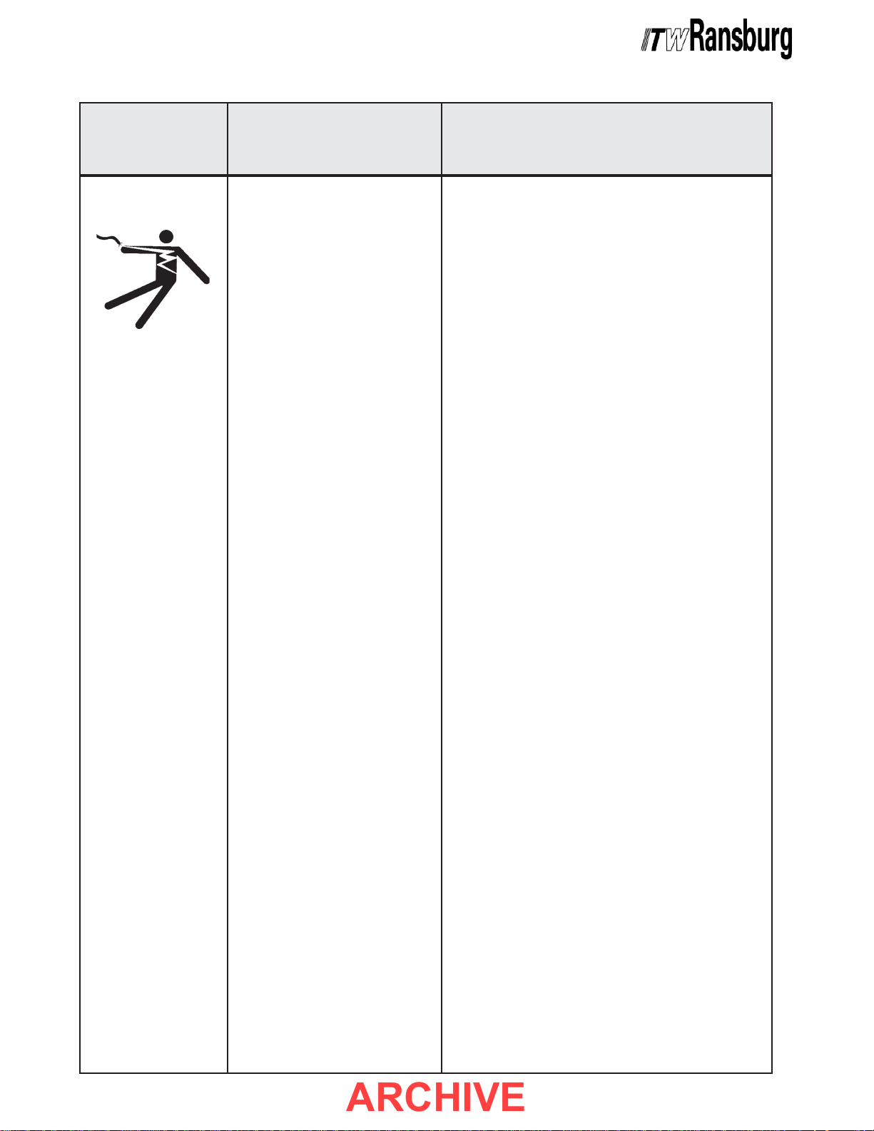
Electrostatic Arcing Ensure the Ground Wire Assembly is connected from the
SAFEGUARDSSAFEGUARDS
SAFEGUARDS
SAFEGUARDSSAFEGUARDS
Tells how to avoid the hazard.
power supply ground stud to a true earth ground.
Ensure that the power supply is plugged into a properly
grounded outlet.
If shocks or sparks are noticed at any point in the spray
system, immediately turn off the power supply and check
the complete system for the cause. DO NOT use the
system again until the problem has been identified and
corrected.
Never operate the applicator without properly grounding the
following:
OperatorsOperators
A.
Operators must be grounded. Rubber soled
OperatorsOperators
insulating shoes should not be worn. Grounding
leg straps may be used.
Operators must maintain contact with the handle of
the applicator. If work gloves are used, the palm
section should be cut out.
Operators must remove from themselves all metal
objects that are not grounded.
NOTE:NOTE:
NOTE: REFER TO NFPA-33, REGARDING OPERATOR
NOTE:NOTE:
GROUNDING.
B. Parts being sprayed. Resistance between the part and
a grounded conveyor must not exceed 1 megohm.
C. Every metal and conductive object in the spray
area. This includes the booth, parts hangers, fire
extinguishers, conductive flooring, etc.
Grounded conductive flooring must be provided in the
spray area.
Turn off voltage at the power supply before flushing out,
cleaning, or removing any parts from the applicator.
Provide proper protection for waterborne supply systems.
Never install an applicator into a fluid system using an
isolated solvent supply.
Always discharge Waterborne system capacitance prior to
servicing.
33
3
33
Do not touch applicator electrode while applicator is
energized.
CP-97-02.5
Page 7
9040 Classic for REA & M90 Systems - Safety
ARCHIVE
AREAAREA
AREA
AREAAREA
Tells where hazards
may occur.
General Use andGeneral Use and
General Use and
General Use andGeneral Use and
MaintenanceMaintenance
Maintenance
MaintenanceMaintenance
HAZARDHAZARD
HAZARD
HAZARDHAZARD
Tells what the hazard is.
Improper operation or maintenance
may create a hazard.
Personnel must be properly trained
in the use of this equipment.
SAFEGUARDSSAFEGUARDS
SAFEGUARDS
SAFEGUARDSSAFEGUARDS
Tells how to avoid the hazard.
Personnel must be given training in accordance with
the requirements of NFPA-33.
Instructions and safety precautions must be read
and understood prior to using this equipment.
Comply with appropriate local, state, and national
codes governing ventilation, fire protection, operation
maintenance, and housekeeping. Reference OSHA,
NFPA-33,and your insurance company requirements.
Always turn power to the power supply OFF, unplug
the electrical cord from its outlet, and remove the
front panel fuse, before opening the power supply
door. If necessary, lock the power supply out so that
it cannot be turned ON until the work is finished.
Whenever removing high voltage cables from
equipment, ground the contact end of the cable by
holding the cable such that the contact touches
earth ground for several seconds. Do not touch the
contact until it has been grounded. This will reduce
the possibility of residual charge causing electrical
shock.
Explosion Hazard/Explosion Hazard/
Explosion Hazard/
Explosion Hazard/Explosion Hazard/
IncompatibleIncompatible
Incompatible
IncompatibleIncompatible
MaterialsMaterials
Materials
MaterialsMaterials
Halogenated hydrocarbon
solvents
chloride and 1,1,1,-Trichloroethane
are not chemically compatible with
the aluminum that might be used
in many system components. The
chemical reaction caused by these
solvents reacting with aluminum
can become violent and lead to an
equipment explosion.
for example: methylene
The High Voltage Multiplier Assembly contains energy
storage components that can cause serious shock
injury, and therefore is not field repairable. Warranty
will be voided if the High Voltage Multiplier seal is
broken. If the High Voltage Multiplier is defective
contact your authorized ITW Ransburg representative
for exchange or repair.
The High Voltage Multiplier and high voltage cable
contain significant capacitance that will store charge.
Allow approximately 10 seconds for this charge to
bleed off before opening the cabinet door or removing
the high voltage cable from the power supply or
spray applicator.
Aluminum is widely used in other spray application
equipment - such as material pumps, regulators,
triggering valves, etc. Halogenated hydrocarbon
solvents must never be used with aluminum
equipment during spraying, flushing, or cleaning.
Read the label or data sheet for the material you
intend to spray. If in doubt as to whether or not a
coating or cleaning material is compatible, contact
your material supplier. Any other type of solvent
may be used with aluminum equipment.
CP-97-02.5
44
4
44
Page 8
9040 Classic for REA & M90 Systems - Safety
ARCHIVE
AREAAREA
AREA
AREAAREA
Tells where hazards
may occur.
Toxic SubstancesToxic Substances
Toxic Substances
Toxic SubstancesToxic Substances
Personnel SafetyPersonnel Safety
Personnel Safety
Personnel SafetyPersonnel Safety
Personnel SafetyPersonnel Safety
Personnel Safety
Personnel SafetyPersonnel Safety
(High Pressure
Equipment)
HAZARDHAZARD
HAZARD
HAZARDHAZARD
Tells what the hazard is.
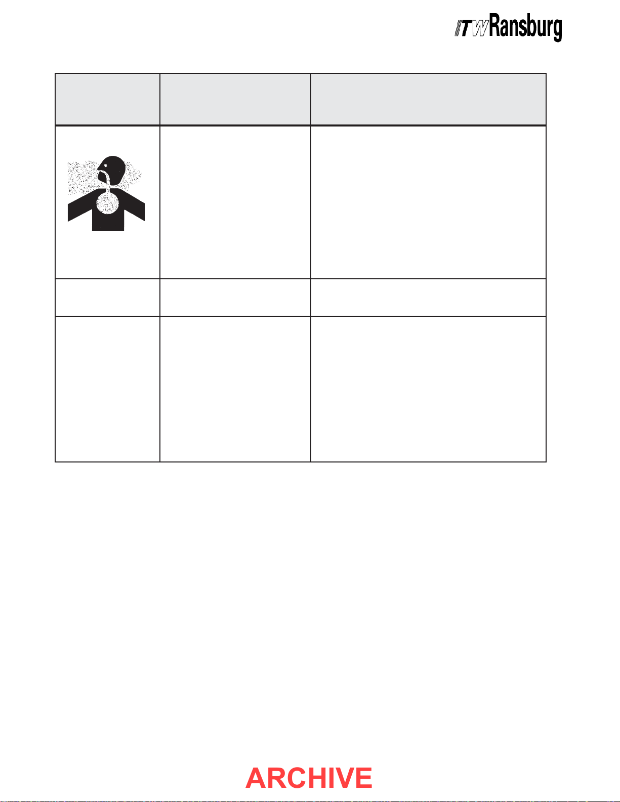
Certain material may be harmful if
inhaled, or if there is contact with
the skin.
Skin puncturing by sharp electrode. Take precautions to see that flesh is not punctured by
Fluid Injection Injury Never let any part of the body come in direct contact
SAFEGUARDSSAFEGUARDS
SAFEGUARDS
SAFEGUARDSSAFEGUARDS
Tells how to avoid the hazard.
Follow the requirements of the Material Safety Data
Sheet supplied by coating material manufacturer.
Adequate exhaust must be provided to keep the air
free of accumulations of toxic materials.
Use a mask or respirator whenever there is a chance
of inhaling sprayed materials. The mask must be
compatible with the material being sprayed and its
concentration. Equipment must be as prescribed by
an industrial hygienist or safety expert, and be NIOSH
approved.
sharp electrode.
with the fluid stream exiting from the nozzle. If fluid
leaks occur in the applicator or in the fluid delivery
components, depressurize fluid system before
servicing.
Never aim the applicator at any part of the body under
any circumstances.
If you are injured by high pressure fluid injection then
immediate medical treatment MUST be sought.
55
5
55
CP-97-02.5
Page 9

9040 Classic for REA & M90 Systems - Safety
ARCHIVE
NOTESNOTES
NOTES
NOTESNOTES
CP-97-02.5
66
6
66
Page 10

9040 Classic for REA & M90 Systems - Atex
ARCHIVE
EUROPEAN AEUROPEAN A
EUROPEAN A
EUROPEAN AEUROPEAN A
The following instructions apply to equipment
covered by certificate number Sira 08ATEX5040X:
1. The equipment may be used with flammable
gases and vapors with apparatus groups II and
with temperature class T6.
2. The equipment is only certified for use in
ambient temperatures in the range +12.8°C to
+40°C and should not be used outside this range.
3. Installation shall be carried out by suitably
trained personnel in accordance with the applicable
code of practice e.g. EN 60079-14:1997.
4. Inspection and maintenance of this equipment
shall be carried out by suitably trained personnel
in accordance with the applicable code of practice
e.g. EN 60079-17.
5. Repair of this equipment shall be carried out by
suitable trained personnel in accordance with the
applicable code of practice e.g. EN 60079-19.
6. Putting into service, use, assembling, and
adjustment of the equipment shall be fitted by
suitably trained personnel in accordance with the
manufacturer's documentation.
Refer to the "Table of Contents" of this service
manual:
a. Installation
b. Operation
c. Maintenance
d. Parts Identification
7. Components to be incorporated into or used as
replacement parts of the equipment shall be fitted
by suitably trained personnel in accordance with
the manufacturer's documentation.
TEX DIRECTIVE 94/9/EC, ANNEX II, 1.0.6TEX DIRECTIVE 94/9/EC, ANNEX II, 1.0.6
TEX DIRECTIVE 94/9/EC, ANNEX II, 1.0.6
TEX DIRECTIVE 94/9/EC, ANNEX II, 1.0.6TEX DIRECTIVE 94/9/EC, ANNEX II, 1.0.6
8. The certification of this equipment relies upon
the following materials used in its construction:
If the equipment is likely to come into contact with
aggressive substances, then it is the responsibility
of the user to take suitable precautions that prevent
it from being adversely affected, thus ensuring
that the type of protection provided by the equipment
is not compromised.
Aggressive substances: e.g. acidic liquids or
gases that may attack metals, or solvents that
may affect polymeric materials.
Suitable precautions: e.g. regular checks as part
of routine inspections or establishing from the
material's data sheets that it is resistant to specific
chemicals.
Refer to "Specifications" in the "Introduction"
section:
a. All fluid passages contain stainless steel
or nylon fittings.
b. High voltage cascade is encapsulated with
a solvent resistant epoxy.
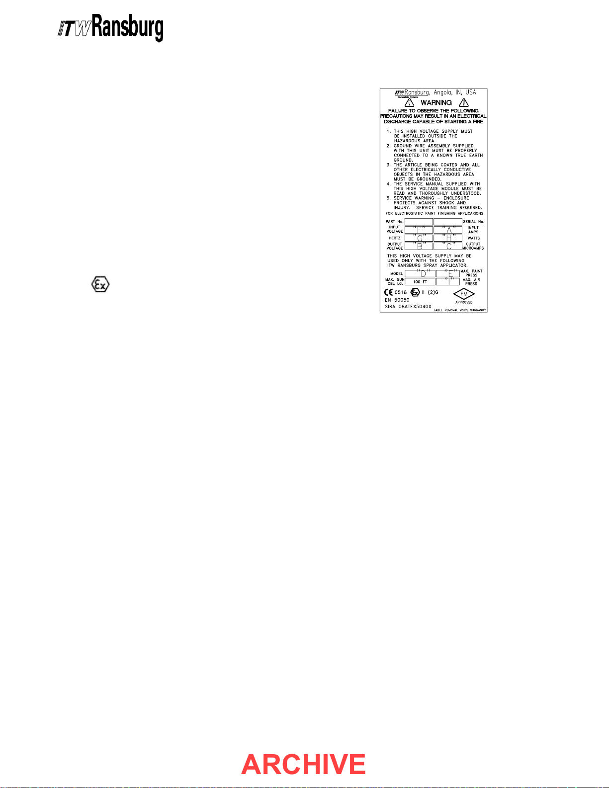
9. A recapitulation of the certification marking is
detailed in the "Atex" section, on the next page,
drawing number: 76454-XX.
10. The characteristics of the equipment shall be
detailed e.g. electrical, pressure, and voltage
parameters.
The manufacturer should note that, on being put
into service, the equipment must be accompanied
by a translation of the instructions in the language
or languages of the country in which the equipment
is to be used and by the instructions in the original
language.
77
7
77
CP-97-02.5
Page 11
9040 Classic for REA & M90 Systems - Atex
ARCHIVE
76447-XXX 9040 Classic A76447-XXX 9040 Classic A
76447-XXX 9040 Classic A
76447-XXX 9040 Classic A76447-XXX 9040 Classic A
Product Marking DefinitionsProduct Marking Definitions
Product Marking Definitions
Product Marking DefinitionsProduct Marking Definitions
Ex Certificate Number: Sira 08ATEX5040X
Sira = Notified Body performing EC-type
examination
08 = Year of certification
ATEX = Reference to ATEX Directive
5 = Protection Concept Code (code 5 is titled
Encapsulation)
040 = Document serial number
X = Special conditions for safe use apply
Product Marking
II 2 G
Ex = Specific marking of explosive protection
II = Equipment Group hazardous area characteristics
2 = Equipment Category
G = Type of explosive atmosphere (gases, vapors,
or mists)
TEXTEX
TEX
TEXTEX
Label 76454Label 76454
Label 76454
Label 76454Label 76454
EEx 0.24mJEEx 0.24mJ
EEx 0.24mJ = The 76447 9040 Classic Power
EEx 0.24mJEEx 0.24mJ
Supply is suitable for use in electrostatic spraying
installations complying with EN 50050 as they are
a Type A class with a discharge energy limit of
0.24mJ.
CP-97-02.5
88
8
88
Page 12

9040 Classic for REA & M90 Systems - Introduction
ARCHIVE
INTRODUCTIONINTRODUCTION
INTRODUCTION
INTRODUCTIONINTRODUCTION
GENERAL DESCRIPTIONGENERAL DESCRIPTION
GENERAL DESCRIPTION
GENERAL DESCRIPTIONGENERAL DESCRIPTION
The ITW Ransburg REA ProcessThe ITW Ransburg REA Process
The ITW Ransburg REA Process
The ITW Ransburg REA ProcessThe ITW Ransburg REA Process
The REA Process is an air atomized method for
applying coatings to objects electrostatically. The
REA system applies a high voltage DC charge to
the applicator nozzle electrode, creating an
electrostatic field between the atomizer and the
target object. The target is electrically grounded
through its support which may be either stationary
or moving.
A regulated pressure fluid system delivers coating
material to the atomizer. At the atomizer, air is
applied which atomizes the coating material forming
a spray mist which, under the influence of the
electrostatic field, becomes electrically charged.
The charged particles are attracted to, and
deposited on, the target object. The forces between
the charged particles and the grounded target are
sufficient to turn most normal over-spray around
and deposit it on the side and back surfaces of the
target. Therefore, a high percentage of the spray
is deposited on the target.
The ITW Ransburg M90 ProcessThe ITW Ransburg M90 Process
The ITW Ransburg M90 Process
The ITW Ransburg M90 ProcessThe ITW Ransburg M90 Process
This is a combined air-airless atomization method
for electrostatically applying coatings to objects.
The M90 system applies a high voltage DC charge
to the applicator nozzle electrode, creating an
electrostatic field between the atomizer and the
target object. The target is electrically grounded
through its support, which may be either stationary
or moving.
the charged particles and the grounded target are
sufficient to turn most normal overspray around
and deposit it on the side and back surfaces of the
target. Thus, a high percentage of the spray is
deposited on the target.
The 9040 Classic High VThe 9040 Classic High V
The 9040 Classic High V
The 9040 Classic High VThe 9040 Classic High V
Power SupplyPower Supply
Power Supply
Power SupplyPower Supply
The 9040 Classic Power Supply converts standard
AC line voltage to a high frequency, low voltage
signal ranging from 0 to 10 Vrms. This signal is
supplied to the High Voltage Multiplier where it is
converted to DC high voltage. The high voltage
DC is then transferred from the 9040 Classic
Power Supply to the REA/M90 applicator through
a super flex high voltage cable. The voltage/
current characteristic is designed to optimize the
charging process under varying load conditions
and to limit the operating current to a safe maximum
value.
In addition to supplying high voltage output to the
applicator, the 9040 Classic Power Supply also
provides controls for AC power ON/OFF, infinite
high voltage adjustment, a high voltage meter, a
current meter, a POWER ON indicator, a HIGH
VOLTAGE ON indicator, and a CURRENT
OVERLOAD indicator and reset switch. Additionally, output terminals are provided for remote
overload reset and interlock connections for a
conveyor, exhaust fan and high voltage control on
all 9040 Classic Power Supplies.
oltageoltage
oltage
oltageoltage
A regulated
coating material to the atomizer. There the coating
material is atomized by passing through an orifice
under pressure. The resulting spray mist then
becomes electrically charged under the influence
of the electrostatic field surrounding the atomizer.
The charged particles are attracted to and
deposited on the target object. The forces between
99
9
99
highhigh
high pressure fluid system delivers
highhigh
CP-97-02.5
Page 13
9040 Classic for REA & M90 Systems - Introduction
ARCHIVE
NOTENOTE
NOTE
NOTENOTE
> The 9040 Classic Power Supply is fac-
tory supplied with a cabinet latch that can
be opened using a slotted screwdriver. If
desired, the standard latch can be easily
replaced with a latch that requires the use
of a key to open. This key lock can be ordered from: Austin Hardware, Inc., 8001
Central Ave. N. E., Minneapolis, MN
55432; 1-800-328-2423; Key Lock Part
Number: C8052-14A.
The 9040 Classic Power Supply is avail-The 9040 Classic Power Supply is avail-
The 9040 Classic Power Supply is avail-
The 9040 Classic Power Supply is avail-The 9040 Classic Power Supply is available for hand and automatic REA andable for hand and automatic REA and
able for hand and automatic REA and
able for hand and automatic REA andable for hand and automatic REA and
M90 applicators as follows:M90 applicators as follows:
M90 applicators as follows:
M90 applicators as follows:M90 applicators as follows:
90409040
9040
90409040
Part #Part #
Part #
Part #Part #
76447-10X
76447-12X
76447-13X
76447-14X
Used WithUsed With
Used With
Used WithUsed With
Applicator TypeApplicator Type
Applicator Type
Applicator TypeApplicator Type
REA-IV Applicator
REA-III Solvent Applicator
REA-III Water Applicator
REA-III Automatic
M90 Classic Applicator
ApplicatorApplicator
Applicator
ApplicatorApplicator
##
#
##
70404
70929
72316
70393
77132
SPECIFICASPECIFICA
SPECIFICA
SPECIFICASPECIFICA
PhysicalPhysical
Physical
PhysicalPhysical
Height:Height:
Height: 14-inches
Height:Height:
Width:Width:
Width:
Width:Width:
Depth:Depth:
Depth: 6-inches
Depth:Depth:
Weight:Weight:
Weight: 24-lbs.
Weight:Weight:
ElectricalElectrical
Electrical
ElectricalElectrical
INPUTINPUT
INPUT
INPUTINPUT
Voltage:Voltage:
Voltage:
Voltage:Voltage:
Current:Current:
Current: 0.6/0.3 Amps AC
Current:Current:
Frequency:Frequency:
Frequency: 50/60 Hertz
Frequency:Frequency:
Wattage:Wattage:
Wattage: 60 Watts (maximum)
Wattage:Wattage:
OUTPUTOUTPUT
OUTPUT
OUTPUTOUTPUT
Voltage:Voltage:
Voltage:
Voltage:Voltage:
TIONSTIONS
TIONS
TIONSTIONS
12-inches
90-264 VAC
0-65kV DC (76447-10x)
0-85kV DC (76447-14x)
0-90kV DC (76447-12x)
0-100kV DC (76447-13x)
NOTENOTE
NOTE
NOTENOTE
> Except where indicated, this manual is
applicable to all models of the 9040 Classic
Power Supply for the REA/M90 Systems.
Current:Current:
Current: 200 Microamps (maximum)
Current:Current:
PneumaticPneumatic
Pneumatic
PneumaticPneumatic
Supply Air:Supply Air:
Supply Air: 100 psi maximum
Supply Air:Supply Air:
CP-97-02.5
1010
10
1010
Page 14
9040 Classic for REA & M90 Systems - Introduction
ARCHIVE
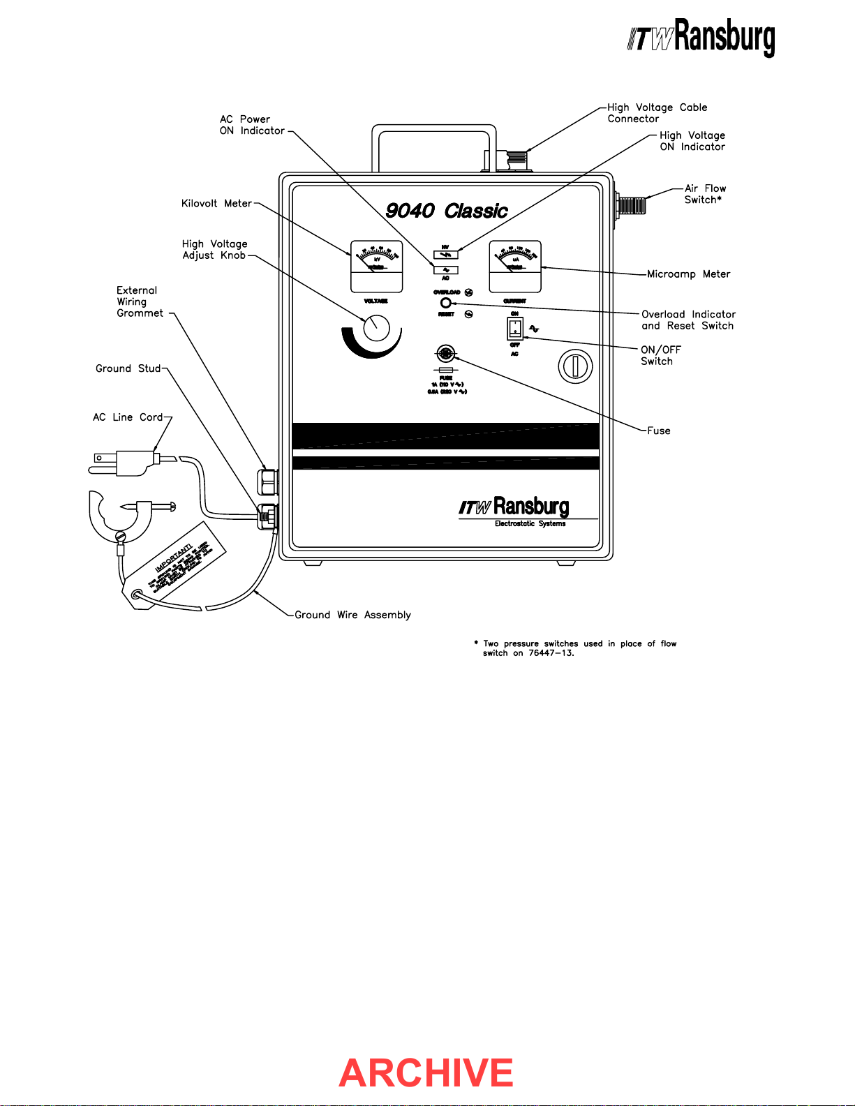
Figure 1: 9040 Classic Power Supply Features for the REA/M90 SystemsFigure 1: 9040 Classic Power Supply Features for the REA/M90 Systems
Figure 1: 9040 Classic Power Supply Features for the REA/M90 Systems
Figure 1: 9040 Classic Power Supply Features for the REA/M90 SystemsFigure 1: 9040 Classic Power Supply Features for the REA/M90 Systems
1111
11
1111
CP-97-02.5
Page 15

9040 Classic for REA & M90 Systems - Installation
ARCHIVE
INSTINST
INST
INSTINST
> The 9040 Classic Power Supply
be located outside the hazardous area.
(See NFPA-33, OSHA, and ITW Ransburg
Bulletin - "Operating Your Electrostatic
Coating System Safely".)
> The user
with the "SAFETY" section of this manual.
> This manual
oughly understood by
operate, clean, or maintain this equipment!
Special care should be taken to ensure that
the warnings and requirements for operating and servicing safely are followed. The
user should be aware of and adhere to
local building and fire codes and ordinances
as well as NFPA-33 and OSHA prior to
installing, operating, and/or servicing this
equipment.
ALLAALLA
ALLA
ALLAALLA
W A R N I N GW A R N I N G
W A R N I N G
W A R N I N GW A R N I N G
!!
!
!!
MUSTMUST
MUST read and be familiar
MUSTMUST
TIONTION
TION
TIONTION
MUSTMUST
MUST be read and thor-
MUSTMUST
ALLALL
ALL personnel who
ALLALL
MUSTMUST
MUST
MUSTMUST
ALLALL
ALL
ALLALL
shown in Figure 2. In either case, the power
supply MUST be mounted in an upright position.
DO NOT DO NOT
DO NOT lay the power supply on its side or back.
DO NOT DO NOT
C A U T I O NC A U T I O N
C A U T I O N
C A U T I O NC A U T I O N
!!
!
!!
DO NOTDO NOT
>
DO NOT locate the power supply
DO NOTDO NOT
near or adjacent to heat producing equipment such as ovens, high wattage lamps,
etc.
Figure 2: Wall Mount BracketsFigure 2: Wall Mount Brackets
Figure 2: Wall Mount Brackets
Figure 2: Wall Mount BracketsFigure 2: Wall Mount Brackets
NOTENOTE
NOTE
NOTENOTE
> As each installation is unique, this infor-
mation is intended to provide general installation information for the 9040 Classic Power
Supply. Consult your authorized ITW Ransburg distributor for specific directions pertaining to the installation of your equipment.
LOCALOCA
LOCA
LOCALOCA
Install the 9040 Classic Power Supply in an area
outside the hazardous location, where it will be
protected from the possibility of environmental
intrusion, such as dust or moisture, and ambient
temperatures do not exceed 120oF, but as close to
the applicator as possible to minimize the length of
high voltage cable. The power supply may be free
standing on any flat surface or wall mounted by
rotating the wall mount brackets (supplied) as
TIONTION
TION
TIONTION
INPUTINPUT
INPUT
INPUTINPUT
SELECTIONSELECTION
SELECTION
SELECTIONSELECTION
The 9040 Classic Power Supply accepts universal input voltage between 90 and 264 VAC.
There is no need to change any switch settings
when changing input from 115 to 230 VAC or
from 230 to 115 VAC.
> 9040 units shipped from the factory for
115 VAC input will have a 72771-06, 1 amp
front panel fuse installed. While 9040 units
shipped from the factory for 230 VAC input
will have a 72771-01, 0.5 amp front panel
fuse installed. If the other input is required,
it is recommended that the fuse be changed
in order to keep the same level of protection. Both fuses are shipped with 9040
Power Supplies.
VOL VOL
VOL
VOL VOL
NOTENOTE
NOTE
NOTENOTE
TT
AGEAGE
T
AGE
TT
AGEAGE
CP-97-02.5
1212
12
1212
Page 16
9040 Classic for REA & M90 Systems - Installation
ARCHIVE
Safety GroundSafety Ground
Safety Ground
INPUT CONNECTIONSINPUT CONNECTIONS
INPUT CONNECTIONS
INPUT CONNECTIONSINPUT CONNECTIONS
Plug the AC line cord into a properly grounded
AC outlet.
NOTENOTE
NOTE
NOTENOTE
> In general, conduit must be used for ap-
proved AC installation, however, if national
and local codes permit, the AC power may
be supplied via the factory installed line
cord. If conduit is utilized, the power supply
wiring MAY be routed through an optional
explosion proof switch mounted on or near
the spray booth where it will be convenient
to the operator.
EXTERNALEXTERNAL
EXTERNAL
EXTERNALEXTERNAL
CONNECTIONSCONNECTIONS
CONNECTIONS
CONNECTIONSCONNECTIONS
NOTENOTE
NOTE
NOTENOTE
> When connecting external wires to the
9040 Classic Power Supply, route the wiring through the external wiring grommet
located on the side panel.
Safety GroundSafety Ground
Crimp the appropriate connector onto the ground
wire assembly and install from the power supply
ground stud, located on the side panel, to a true
earth ground.
!!
!
!!
> The Ground Wire Assembly
connected from the Power Supply Ground
Stud to a true earth ground.
InterlocksInterlocks
Interlocks
InterlocksInterlocks
!!
!
!!
ALWAYSALWAYS
>
ALWAYS ensure that high voltage is
ALWAYSALWAYS
OFFOFF
OFF before flushing the spray gun with
OFFOFF
solvent.
with high voltage
hazard and risk to personnel safety. It is
recommended that the high voltage control
be interlocked with the solvent flush signal
so that high voltage is automatically locked
out whenever flushing occurs. Consult your
authorized ITW Ransburg representative for
information on interlocking the high voltage
OFFOFF
OFF signal with the solvent flush signal.
OFFOFF
NEVER NEVER
NEVER flush the spray applicator
NEVER NEVER
C A U T I O NC A U T I O N
C A U T I O N
C A U T I O NC A U T I O N
W A R N I N GW A R N I N G
W A R N I N G
W A R N I N GW A R N I N G
ONON
ON, as this is a severe fire
ONON
MUSTMUST
MUST be
MUSTMUST
High VHigh V
High V
High VHigh V
Cable ConnectionCable Connection
Cable Connection
Cable ConnectionCable Connection
Remove the plastic protective plug from the High
Voltage Cable Connector and squirt enough
dielectric oil (70863-00 (supplied)) into the high
voltage tube to cover the electrical contact point.
> Squirting 70863-00 dielectric oil down
the high voltage tube significantly reduces
corona discharge that can cause deterioration of the high voltage connection components.
With a clean, dry cloth, wipe the end of the high
voltage cable. Insert the high voltage cable into
the high voltage cable connector and tighten the
cable nut securely.
1313
13
1313
oltage (High Voltage (High V
oltage (High V
oltage (High Voltage (High V
NOTENOTE
NOTE
NOTENOTE
oltage)oltage)
oltage)
oltage)oltage)
As outlined in NFPA-33 and OSHA, the AC power
line must be series interlocked with both the
exhaust fan and conveyor. To interlock the 9040
Classic Power Supply with the exhaust fan and
conveyor, perform the following:
1. Ensure the front panel fuse is removed, the
power supply is unplugged, and the ON/OFF
switch is in the OFF position.
2. Open the power supply cabinet door.
W A R N I N GW A R N I N G
W A R N I N G
W A R N I N GW A R N I N G
!!
!
!!
ALWAYSALWAYS
>
ALWAYS
ALWAYSALWAYS
supply is unplugged from its AC outlet
before working with any internal wiring.
double check that the power
CP-97-02.5
Page 17
9040 Classic for REA & M90 Systems - Installation
ARCHIVE
3. Using a small blade screwdriver, remove the
factory installed test jumper from 1TB-L1to 1TBL2.
4. Route exhaust fan and conveyor interlock
(supplied by user) wiring through the external
wiring grommet on the side of the power supply
and connect to 1TB-L1 and 1TB-L2 as shown in
Figure 3.
rated for at least 1 Amp at 240 volts AC.rated for at least 1 Amp at 240 volts AC.
rated for at least 1 Amp at 240 volts AC.
rated for at least 1 Amp at 240 volts AC.rated for at least 1 Amp at 240 volts AC.
5. Secure the cabinet door, replace the fuse and
plug the power supply in.
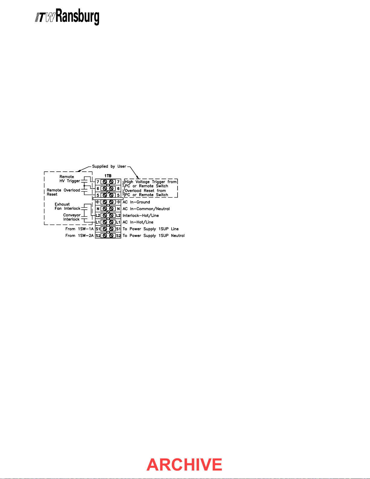
Figure 3: Terminal Block One (1TB)Figure 3: Terminal Block One (1TB)
Figure 3: Terminal Block One (1TB)
Figure 3: Terminal Block One (1TB)Figure 3: Terminal Block One (1TB)
The interlock contacts should beThe interlock contacts should be
The interlock contacts should be
The interlock contacts should beThe interlock contacts should be
When the applicator is triggered, the resulting air
flow closes the contacts of the air flow switch,
thereby activating high voltage at the applicator.
Pneumatic ConnectionsPneumatic Connections
Pneumatic Connections
Pneumatic ConnectionsPneumatic Connections
(76447-13x)(76447-13x)
(76447-13x)
(76447-13x)(76447-13x)
Connect an atomization air pressure signal to one
pressure switch port and a trigger air pressure
signal to the other. When pressure signals (25 psi
minimum, 100 psi maximum) are applied to both
switches their contacts close, thereby activating
high voltage at the applicator. Both pressure
switches must be activated to receive high voltage.
External High VExternal High V
External High V
External High VExternal High V
If a method of high voltage triggering, other than
the factory supplied method, is required, the 9040
Classic power supply allows for external high
voltage control from a PLC, pressure switch, air
flow switch, or other user supplied device. To turn
the high voltage on, the user supplied device must
create a contact closure between terminals 6 and
7 of terminal block one (1TB). To connect the user
supplied, external high voltage control device,
perform the following:
oltage Controloltage Control
oltage Control
oltage Controloltage Control
External Relay ContactsExternal Relay Contacts
External Relay Contacts
External Relay ContactsExternal Relay Contacts
A set of external relay contacts for high voltage
(K1) and overload (K2) conditions is provided at
6PL-5, -6 & -7. See Figure 10 for exact wiring
locations. These relay contacts are sometimes
useful in configuring the control of the applicator
system.
Pneumatic ConnectionsPneumatic Connections
Pneumatic Connections
Pneumatic ConnectionsPneumatic Connections
(76447-10x, -12x, & -14x)(76447-10x, -12x, & -14x)
(76447-10x, -12x, & -14x)
(76447-10x, -12x, & -14x)(76447-10x, -12x, & -14x)
Connect the Air Filter Assembly (supplied) to the
IN port of the air flow switch on the side of the 9040
Classic power supply. Connect regulated (100
psi maximum) factory air to the other end of the Air
Filter Assembly. Be sure that the fittings remain
clean and are securely tightened. Attach the
applicator air line to the OUT port of the air flow
switch.
1. Ensure the front panel fuse is removed, the
power supply is unplugged, and the ON/OFF
switch is in the OFF position.
2. Open the power supply cabinet door.
3. Route the contact wires of the control device
through the external wiring grommet and connect
to the existing wiring for 1TB-6 and 1TB-7.
control device contacts must be rated for atcontrol device contacts must be rated for at
control device contacts must be rated for at
control device contacts must be rated for atcontrol device contacts must be rated for at
least 100 millamps at 15 volts DC.least 100 millamps at 15 volts DC.
least 100 millamps at 15 volts DC.
least 100 millamps at 15 volts DC.least 100 millamps at 15 volts DC.
4. Secure the cabinet door, replace the fuse, and
plug in the power supply.
TheThe
The
TheThe
CP-97-02.5
1414
14
1414
Page 18

9040 Classic for REA & M90 Systems - Installation
ARCHIVE
External Overload ResetExternal Overload Reset
External Overload Reset
External Overload ResetExternal Overload Reset
The 9040 Classic power supply allows for use of
an external (normally closed) overload reset button.
This is convenient when the power supply is
mounted in a hard to reach or inconvenient location
or when it is desired to control overload reset of
several power supplies from a single location.
To utilize the external overload reset perform the
following:
1. Ensure the front panel fuse is removed, the
power supply is unplugged and the ON/OFF switch
is in the OFF position.
2. Open the power supply cabinet door.
3. Remove the factory installed jumper from 1TB5 to 1TB-6 and replace with contact wires of the
external reset device.
contacts must be rated for at least 100contacts must be rated for at least 100
contacts must be rated for at least 100
contacts must be rated for at least 100contacts must be rated for at least 100
milliamps at 15 volts DC. The contacts ofmilliamps at 15 volts DC. The contacts of
milliamps at 15 volts DC. The contacts of
milliamps at 15 volts DC. The contacts ofmilliamps at 15 volts DC. The contacts of
the external reset device must be normallythe external reset device must be normally
the external reset device must be normally
the external reset device must be normallythe external reset device must be normally
closed.closed.
closed.
closed.closed.
The external reset deviceThe external reset device
The external reset device
The external reset deviceThe external reset device
NOTESNOTES
NOTES
NOTESNOTES
4. Secure the cabinet door, replace the fuse, and
plug in the power supply.
1515
15
1515
CP-97-02.5
Page 19
9040 Classic for REA & M90 Systems - Installation
ARCHIVE
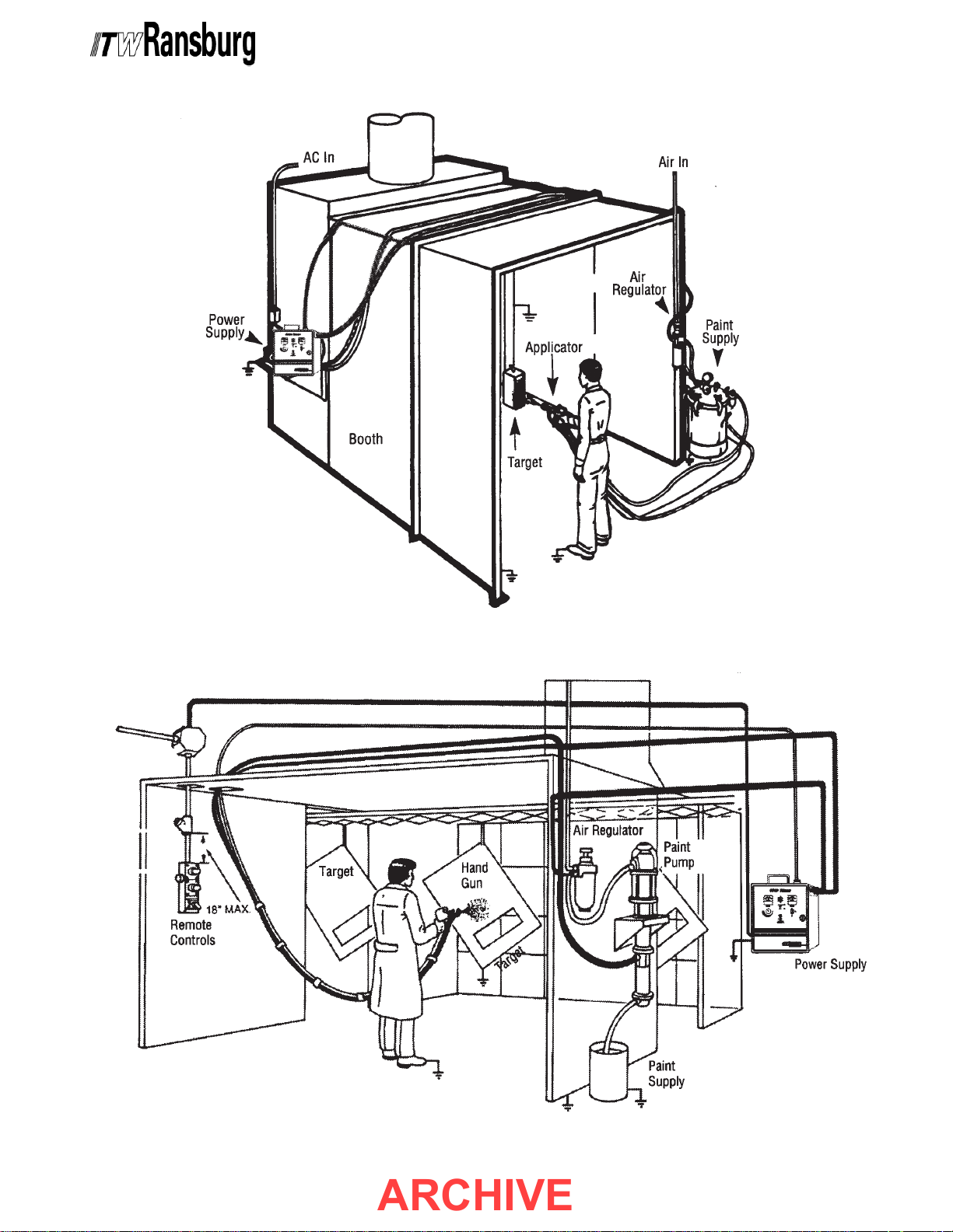
Figure 4: Typical REA Applicator InstallationFigure 4: Typical REA Applicator Installation
Figure 4: Typical REA Applicator Installation
Figure 4: Typical REA Applicator InstallationFigure 4: Typical REA Applicator Installation
CP-97-02.5
Figure 5: Typical M90 Applicator InstallationFigure 5: Typical M90 Applicator Installation
Figure 5: Typical M90 Applicator Installation
Figure 5: Typical M90 Applicator InstallationFigure 5: Typical M90 Applicator Installation
1616
16
1616
Page 20
9040 Classic for REA & M90 Systems - Operation
ARCHIVE
OPERAOPERA
OPERA
OPERAOPERA
TIONTION
TION
TIONTION
W A R N I N GW A R N I N G
W A R N I N G
W A R N I N GW A R N I N G
!!
!
!!
> The user
with the
"Safety" Section "Safety" Section
"Safety" Section in this manual and the
"Safety" Section "Safety" Section
ITW Ransburg safety literature therein
identified
9040 Classic power supply.
1717
17
1717
MUST MUST
MUST read and be familiar
MUST MUST
Safety Precautions Safety Precautions
Safety Precautions and
Safety Precautions Safety Precautions
BEFORE OPERATING BEFORE OPERATING
BEFORE OPERATING the
BEFORE OPERATING BEFORE OPERATING
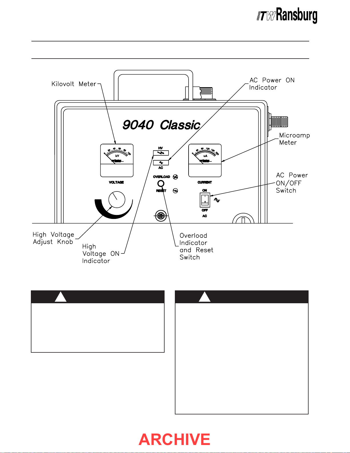
Figure 6: Operating ControlsFigure 6: Operating Controls
Figure 6: Operating Controls
Figure 6: Operating ControlsFigure 6: Operating Controls
!!
!
!!
> The electrical discharge, which is
available from the charging electrode of the
applicator, must not exceed 0.25 mJ of
energy. To achieve this limit, any flow of
energy from the paint supply through the
paint line to the applicator electrode
be prevented by grounding the paint line at
the applicator handle or body.
the applicator is actually grounded
FOREFORE
FORE operating it! (See the appropriate
FOREFORE
applicator manual.) If improper readings are
obtained, check that the power supply is
grounded. (See "Ground Test Procedure" in
the "Maintenance" section of this manual).
W A R N I N GW A R N I N G
W A R N I N G
W A R N I N GW A R N I N G
MUSTMUST
MUST
MUSTMUST
Verify that
BE-BE-
BE-
BE-BE-
CP-97-02.5
Page 21
9040 Classic for REA & M90 Systems - Operation
ARCHIVE
THEORTHEOR
THEOR
THEORTHEOR
Line voltage (90-264 VAC) is applied to input
terminals 8PL-1 and 8PL-2 of power supply
1SUP through the user supplied exhaust fan and
conveyor interlocks, fuse 1FU and ON/OFF switch
1SW.
The output of power supply 1SUP, through PC
board fuse F2 provides the DC voltage which
powers the PC board regulators and the AC
Power ON LED. The DC input to the oscillator
circuit is obtained from a board regulator through
high voltage adjust knob 1POT. The oscillator
circuit outputs a low voltage, high frequency AC
signal to the High Voltage Multiplier circuit. The
high voltage multiplier circuit rectifies the AC voltage
to DC and steps it up to provide rated kV to the
spray applicator via the high voltage cable. The
high voltage adjust knob controls the level of
output voltage from the oscillator to the High
Voltage Multiplier. In this manner, complete
adjustability from 0 to maximum kV of the spray
applicator is achieved.
YY
OF OPERA OF OPERA
Y
OF OPERA
YY
OF OPERA OF OPERA
TIONTION
TION
TIONTION
4. For testing and troubleshooting, board jumper
JP4 connects 1TB-6 and 7 together, thereby
providing high voltage output (see PC Board Test
Jumper in the "Maintenance" section of this
manual).
OPERAOPERA
OPERA
OPERAOPERA
PROCEDURESPROCEDURES
PROCEDURES
PROCEDURESPROCEDURES
1. Ensure that the AC power, pneumatics and
high voltage cables are connected as described in
the "Installation" section of this manual.
> Check that the power supply is properly
grounded!
2. Be sure that the high voltage adjustment knob
is turned FULLY counter-clockwise.
TINGTING
TING
TINGTING
C A U T I O NC A U T I O N
C A U T I O N
C A U T I O NC A U T I O N
!!
!
!!
The DC input to the oscillator is interlocked with
1TB terminals 6 and 7, such that the oscillator
will not function unless terminals 6 and 7 are
connected together. In this manner, high voltage
to the spray applicator is controlled as follows:
1. When air flows through the flow switch, the
switch contacts close connecting 1TB-6 and 7
together, thereby providing voltage to the REA-III,
REA-IV, and M90 Classic applicators.
2. When pressure signals are supplied to the
pressure switches, the switch contacts close
connecting 1TB-6 and 7 together, thereby providing
voltage to the REA-III automatic applicator.
3. Contact closure of a programmable controller
output, robot output, or some other user supplied
device connected to terminals 1TB-6 and 7 will
activate high voltage at the spray applicator.
3. Turn the ON/OFF switch to the ON position.
The green LED will light indicating that AC power
is being supplied to the power supply.
4. The voltage to the REA-III, REA-IV, and M90
Classic applicators is activated by supplying
adequate air to the flow switch when the applicator
is triggered. The voltage to the REA III Automatic
applicator is activated by supplying adequate
pressure signals to the power supply pressure
switches.
5. Turn the voltage adjustment knob to the desired
operating point as indicated by the kilovolt and
microamp meters.
Kilovolt and Microamp MetersKilovolt and Microamp Meters
Kilovolt and Microamp Meters
Kilovolt and Microamp MetersKilovolt and Microamp Meters
The kilovolt meter indicates the voltage in thousands
of volts (kV) present at the spray applicator. The
microamp meter indicates the current in millionths
of amps (μA) leaving the electrode.
CP-97-02.5
1818
18
1818
Page 22
9040 Classic for REA & M90 Systems - Operation
ARCHIVE
High VHigh V
High V
High VHigh V
The high voltage adjustment knob allows infinite
control of the spray applicator electrode voltage
between 0 and rated kV.
Overload Indicator/Reset ButtonOverload Indicator/Reset Button
Overload Indicator/Reset Button
Overload Indicator/Reset ButtonOverload Indicator/Reset Button
Lighting of the yellow overload/reset lamp indicates
that an overload condition has occurred. The
overload circuitry is integral to the power supply
and is factory calibrated and sealed. It allows
normal operation, testing, and maintenance. It will
only activate if the spray applicator current exceeds
the preset limit as a result of component (barrel,
transformer, cable) failure or improper applicator
to target distance. If the overload should trip,
locate and correct the problem. Then reset the
overload by pushing the reset switch in, or turning
the ON/OFF switch OFF and back ON again.
The overload feature can be turned ON or OFF by
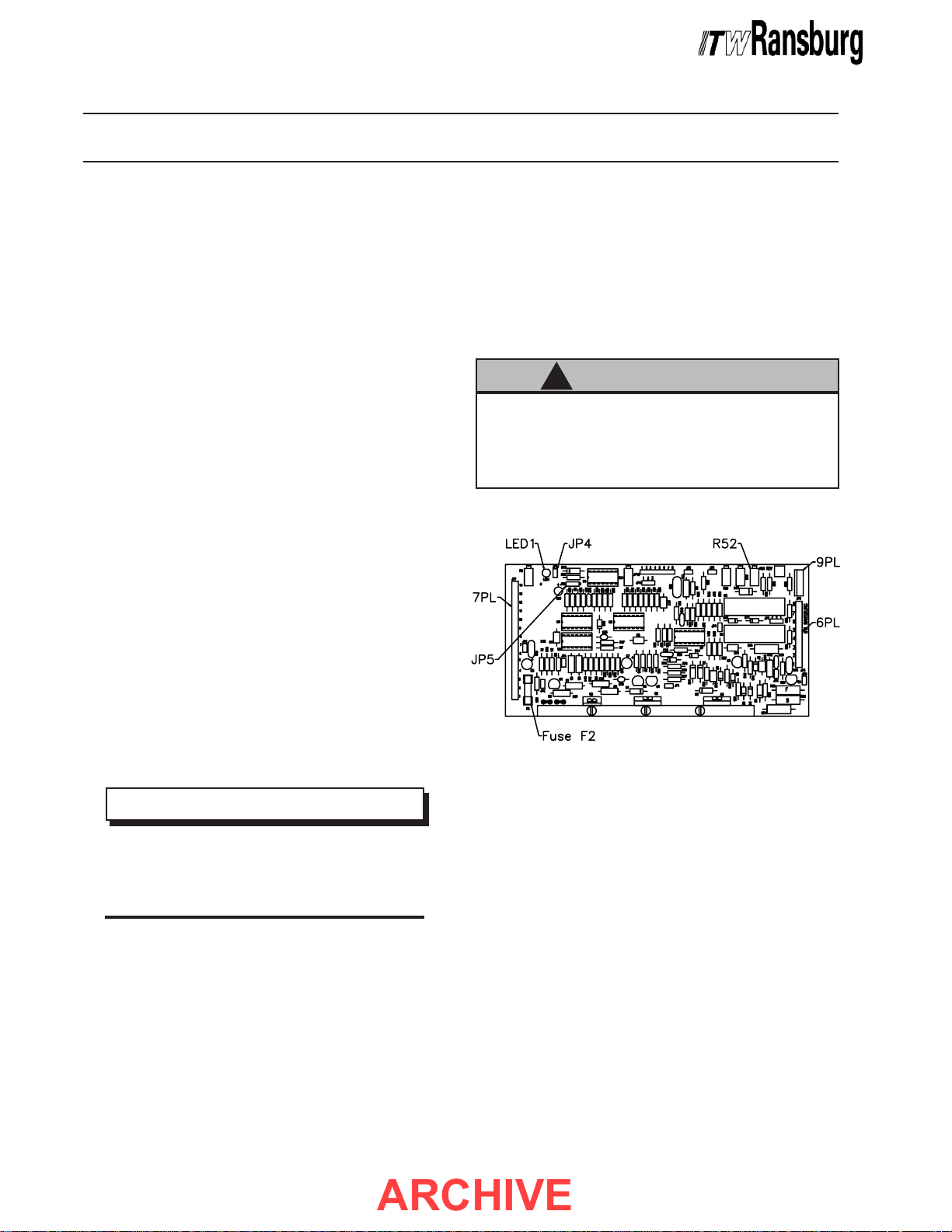
moving jumper JP5 on the main PC Board (see
Figure 7, in the "Maintenance" section of this
manual, for location of JP5). To turn the overload
circuit OFF, position jumper JP5 so that it covers
(shorts) pins 1 and 2. To turn the overload circuit
ON, position jumper JP5 so that it covers (shorts)
pins 2 and 3.
oltage Adjustment Knoboltage Adjustment Knob
oltage Adjustment Knob
oltage Adjustment Knoboltage Adjustment Knob
NOTENOTE
NOTE
NOTENOTE
> Power supplies for applicators are
shipped from the factory with the overload
circuit OFF, while those for automatic applicators are shipped with the overload circuit
ON. This is because during normal use,
manually operated applicators may come in
close proximity to the part, causing an overload which requires the operator to cease
the painting operation while going to reset
the overload. In addition, the operator will
notice when a failed part may be causing
the spray applicator to operate at less than
optimum performance, thus the overload
circuit is not necessary for this purpose.
Automatic applicators, however, typically
have a fixed distance between electrode
and target and
thus it is not likely that the spray applicator
would come into close proximity with the
part during normal use. If it should, then it is
desired that an overload occur to alert maintenance so that the condition can be corrected. Additionally, since there is no operator with automatic applicators, the overload
circuit is required to alert maintenance when
failed parts may be causing the spray applicator to operate at less than optimum performance.
When turning the overload circuit ON for applicator
units it may be necessary to adjust the setpoint at
which overload occurs. If so, contact your
authorized ITW Ransburg representative for
assistance.
High VHigh V
High V
High VHigh V
The 9040 Printed Circuit Board (PCB) contains a
safety circuit that prevents high voltage from being
present at the applicator if the high voltage trigger
device (flow switch, pressure switch, PC contact,
etc.) has not been triggered. If a failure mode
should occur that would attempt to send high
voltage to the applicator, even though the high
voltage trigger has not been activated, the PC
board will shut down and enter an overload
condition. If repeated overloads occur, every time
the overload reset button is pushed, open the
cabinet door and see if the red LED (LED1, see
Figure 7, in the "Maintenance" section of this
manual for location) on the PC Board lights for
about 2 seconds after pushing the reset button. If
it does, the PC Board has failed and should be
replaced.
High VHigh V
High V
High VHigh V
The red high voltage on LED will light when high
voltage is present at the spray applicator.
AC Power ON IndicatorAC Power ON Indicator
AC Power ON Indicator
AC Power ON IndicatorAC Power ON Indicator
The green AC power ON LED will light when the
AC Power ON/OFF switch is in the ON position.
oltage Safety Circuitoltage Safety Circuit
oltage Safety Circuit
oltage Safety Circuitoltage Safety Circuit
oltage ON Indicatoroltage ON Indicator
oltage ON Indicator
oltage ON Indicatoroltage ON Indicator
("Note" continued in next column)
1919
19
1919
CP-97-02.5
Page 23

9040 Classic for REA & M90 Systems - Maintenance
ARCHIVE
NOTESNOTES
NOTES
NOTESNOTES
CP-97-02.5
2020
20
2020
Page 24
9040 Classic for REA & M90 Systems - Operation
ARCHIVE
MAINTENANCEMAINTENANCE
MAINTENANCE
MAINTENANCEMAINTENANCE
ROUTINE PREVENTIVEROUTINE PREVENTIVE
ROUTINE PREVENTIVE
ROUTINE PREVENTIVEROUTINE PREVENTIVE
MAINTENANCEMAINTENANCE
MAINTENANCE
MAINTENANCEMAINTENANCE
In general, little maintenance is necessary to
ensure proper operation. However, it is important
to keep the interior of the unit clean and free from
moisture or foreign material. For this reason the
following must be done:
1. Keep the exterior of the unit free from dust
accumulation.
2. Always clean the exterior prior to opening the
cabinet door.
3. Open the cabinet door only to perform
maintenance or repair.
4. If the power supply end of the high voltage
cable becomes dirty, clean the end of the cable
with a suitable, clean, non-polar solvent and apply
a light coat of dielectric grease. On a yearly basis,
check to ensure that the dielectric oil (70863-00) is
covering the electrical contact point in the high
voltage tube. If not, add oil as needed.
obtained without the need to trigger the spray
applicator or user supplied control device. Just
remember to reposition the jumper after testing, so
that it covers only one terminal or the high voltage
will stay on all the time. (See Figure 7 for location
of test jumper JP4.)
C A U T I O NC A U T I O N
C A U T I O N
C A U T I O NC A U T I O N
!!
!
!!
> If JP4 is left covering (shorting) both
terminals, high voltage will be on whenever
AC power is turned on. This could be
hazardous in some applications.
> Squirting 70863-00 dielectric oil down
the HV tube significantly reduces corona
discharge that can cause deterioration of
the HV connection components.
TROUBLESHOOTINGTROUBLESHOOTING
TROUBLESHOOTING
TROUBLESHOOTINGTROUBLESHOOTING
PC Board TPC Board T
PC Board T
PC Board TPC Board T
To assist in testing and troubleshooting, a jumper
(JP4) has been incorporated on the 9040 PC
Board. By covering (shorting) both terminals, the
high voltage on relay is triggered. Thus, for testing
and troubleshooting, high voltage output can be
2121
21
2121
NOTENOTE
NOTE
NOTENOTE
est Jumperest Jumper
est Jumper
est Jumperest Jumper
Figure 7: Main PC BoardFigure 7: Main PC Board
Figure 7: Main PC Board
Figure 7: Main PC BoardFigure 7: Main PC Board
Ground TGround T
Ground T
Ground TGround T
Equipment Required:Equipment Required:
Equipment Required:
Equipment Required:Equipment Required:
- Ohmmeter (to measure resistance)
If shocks or sparks are noticed at any point in the
spray system, immediately turn off the power
supply and check the complete system for proper
grounding. Proper grounding of the spray applicator
system can be verified as follows:
1. Ensure that the clamp of the 14 AWG ground
wire assembly is connected to true earth ground.
The resistance between the clamp and a known
earth ground should read less than 25 ohms.
est Procedureest Procedure
est Procedure
est Procedureest Procedure
CP-97-02.5
Page 25
9040 Classic for REA & M90 Systems - Maintenance
ARCHIVE
2. Place one end of the ohmmeter on the clamp of
the ground wire assembly and the other end on the
power supply ground stud. If the ohmmeter reads
greater than 25 ohms, replace the 14 AWG ground
wire assembly.
3. Connect one end of the ohmmeter to the Power
Supply Ground Stud and the other to the metal
applicator body (automatics) or handle bracket
(applicators). If the ohmmeter reads greater than
25 ohms, repair or replace the high voltage cable.
NOTENOTE
NOTE
NOTENOTE
> On applicators, ground is passed from
the high voltage cable to the handle by
way of the handle set screw. Ensure the
set screw is completely tightened and repeat step 3 before replacing the high voltage cable on applicator units.
3. Turn the high voltage adjust knob FULLY
counter-clockwise.
4. Open the cabinet door and position jumper JP4
on the main PC Board so that it covers (shorts)
both terminals.
5. Attach the appropriate high voltage cable to the
20791 Test Probe, properly ground the probe to a
true earth ground, and turn the test probe meter on
(see the "Operation Manual" for the 20791 Tester).
6. Insert the Test Probe High Voltage cable into
the power supply high voltage tube until it bottoms
out.
NOTENOTE
NOTE
NOTENOTE
> Ensure that the Test Probe high volt-
age cable makes good contact both inside
the Test Probe and inside the Power Supply High Voltage Tube.
kV Output TkV Output T
kV Output T
kV Output TkV Output T
When a lack of high voltage at the spray applicator
indicates a problem, perform a kV Output Test of
the power supply to determine whether it is at fault.
Equipment Required:Equipment Required:
Equipment Required:
Equipment Required:Equipment Required:
- Calibrated ITW Ransburg 20791 High Voltage
Test Probe & Meter
kV Output Test ProcedurekV Output Test Procedure
kV Output Test Procedure
kV Output Test ProcedurekV Output Test Procedure
1. Turn AC power to the power supply
2. Remove the high voltage cable from the power
supply.
!!
!
!!
estest
est
estest
W A R N I N GW A R N I N G
W A R N I N G
W A R N I N GW A R N I N G
OFFOFF
OFF.
OFFOFF
> Whenever removing high voltage cables
from equipment, ground the plug end of the
cable(s) by contacting the plug to electrical
ground.
been grounded. This will eliminate the
possibility of residual charge causing electrical shock.
DO NOT DO NOT
DO NOT touch the plug until it has
DO NOT DO NOT
7. Turn the power supply ON.
8. Turn the high voltage adjust knob FULLY
clockwise and read the output voltage displayed
on the meter, then turn the power supply OFF. If
the voltage read correctly (see "Specifications" in
the "Introduction" section of this manual), the
problem is not in the power supply and the high
voltage cable and spray applicator should be
checked for the cause. If the voltage did not read
correctly, the problem is with the power supply.
Consult the "Troubleshooting Guide" to locate the
specific problem.
9. Disconnect the 20791 Test Probe and reposition
JP4 so that it covers only one terminal. When
ready to resume spray operations, reconnect the
spray applicator high voltage cable and turn the
power supply on.
Current Output (SCI) TCurrent Output (SCI) T
Current Output (SCI) T
Current Output (SCI) TCurrent Output (SCI) T
When a lack of high voltage at the applicator
indicates a problem a Current Output (SCI) Test
may be performed, in addition to the kV output test,
to help determine if the power supply is at fault.
estest
est
estest
CP-97-02.5
2222
22
2222
Page 26
9040 Classic for REA & M90 Systems - Maintenance
ARCHIVE
Equipment Required:Equipment Required:
Equipment Required:
Equipment Required:Equipment Required:
- Test Resistor (16688-01)
- Current Meter (76652-02)
1. Turn AC power to the power supply
OFFOFF
OFF.
OFFOFF
reading is not within the specified range refer to
"Bench Testing" in the "Maintenance" section of
this manual. If the external current meter reads
correctly, but the meter on the power supply does
not, replace the power supply meter.
2. Remove the high voltage cable from the power
supply.
W A R N I N GW A R N I N G
W A R N I N G
W A R N I N GW A R N I N G
!!
!
!!
> Whenever removing high voltage cables
from equipment, ground the plug end of the
cable(s) by contacting the plug to electrical
ground.
been grounded. This will eliminate the
possibility of residual charge causing electrical shock.
3. Turn the high voltage adjust knob FULLY
counter-clockwise.
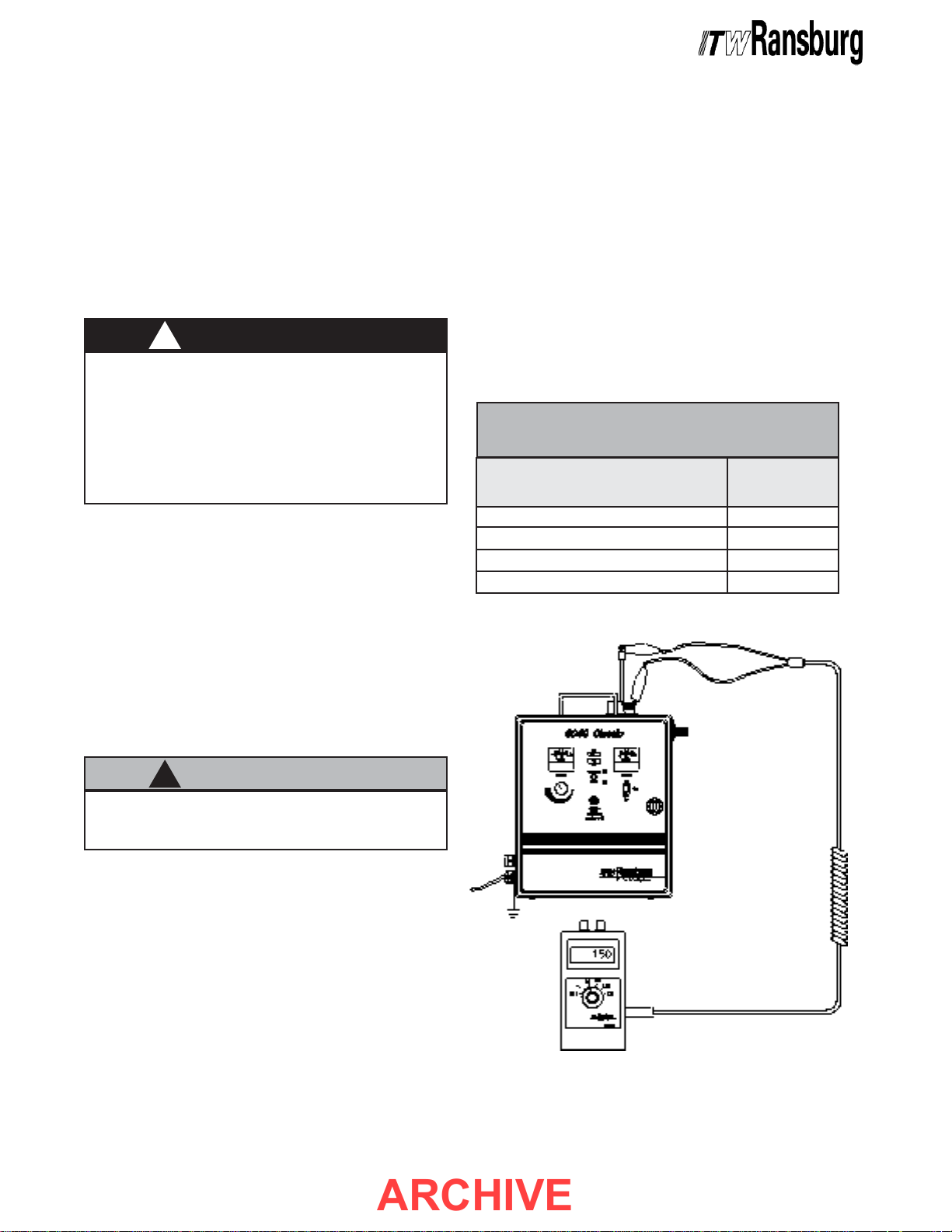
4. Connect one end of the test resistor (16688-
01) through the current meter (76652-02) to ground
as shown in Figure 8. Insert the other end of the
test resistor into the HV output tube of the
power supply.
DO NOT DO NOT
DO NOT touch the plug until it has
DO NOT DO NOT
8. Turn the power supply OFF. Disconnect the
current meter (76652-02) and remove the test
resistor (16688-01). Reposition JP4 so that it
covers only one terminal. When ready to resume
spray operations, reconnect the high voltage cable
and turn the power supply ON.
POWER SUPPLIES ANDPOWER SUPPLIES AND
POWER SUPPLIES AND
POWER SUPPLIES ANDPOWER SUPPLIES AND
SCI VALUESSCI VALUES
SCI VALUES
SCI VALUESSCI VALUES
SCI RangeSCI Range
SCI Range
SCI RangeSCI Range
Power SupplyPower Supply
Power Supply
Power SupplyPower Supply
76447-10x, REA-IV
76447-12x, REA-III Applicator
76447-13x, REA-III Automatic
76447-14x, M90 Classic Applicator
(in μA)(in μA)
(in μA)
(in μA)(in μA)
90 - 140 μA
120 - 170 μA
120 - 170 μA
70 - 115 μA
!!
!
!!
> Ensure the current meter (76652-02) is
set to the μA scale.
5. Open the cabinet door and position jumper JP4
on the main PC Board so that it covers (shorts)
both terminals.
6. Turn the AC power to the power supply ON.
7. SLOWLY adjust the kV adjust knob fully
clockwise. The external current meter (76652-02)
should read within the ranges noted in Figure 7. If
it reads correctly, the problem is not in the power
supply and the high voltage cable and spray
applicator should be checked for the cause. If the
2323
23
2323
C A U T I O NC A U T I O N
C A U T I O N
C A U T I O NC A U T I O N
Figure 8: Current Output TestFigure 8: Current Output Test
Figure 8: Current Output Test
Figure 8: Current Output TestFigure 8: Current Output Test
CP-97-02.5
Page 27
9040 Classic for REA & M90 Systems - Maintenance
ARCHIVE
Bench TBench T
Bench T
Bench TBench T
Equipment Required:Equipment Required:
Equipment Required:
Equipment Required:Equipment Required:
- Volt/ohmmeter
The "Troubleshooting Guide" provides information
for troubleshooting the power supply when improper
operation is obtained and the problem has been
traced to the power supply. Proper troubleshooting
should ONLY be accomplished with specific test
equipment by qualified electronics technicians or
authorized ITW Ransburg representatives.
> The troubleshooting procedure outlined
in the "Troubleshooting Guide" requires
measurement of voltage potentials that can
cause
proper measuring procedures are not
followed. For this reason, proper troubleshooting should
with specific test equipment by qualified
electronics technicians or authorized ITW
Ransburg representatives.
estingesting
esting
estingesting
W A R N I N GW A R N I N G
W A R N I N G
W A R N I N GW A R N I N G
!!
!
!!
SERIOUS BODILY INJURY SERIOUS BODILY INJURY
SERIOUS BODILY INJURY if
SERIOUS BODILY INJURY SERIOUS BODILY INJURY
ONLY ONLY
ONLY be accomplished
ONLY ONLY
NOTENOTE
NOTE
NOTENOTE
> Before going through the trouble of a
complete bench test, jumper JP4 on the
main PC Board to trigger the high voltage
and see if the suspected problem goes
away. If it does, replace the high voltage
trigger device (flow switch, pressure
switch, PC contact, etc.) or repair the internal wiring of the power supply connected to the trigger device, and test
again. If the problem does not go away,
then proceed with a bench test.
SERVICE LEVELSERVICE LEVEL
SERVICE LEVEL
SERVICE LEVELSERVICE LEVEL
Personnel who service this unit must be qualified
electronics technicians. Replacement parts are
designed to be made at the assembly level. (See
the "Parts Identification" section of this manual for
replacement assemblies and part numbers.)
Before troubleshooting, ensure that the power
supply is plugged into a live outlet of the appropriate
voltage. All electrical measurements in the
"Troubleshooting Guide" are nominal and may
vary as much as
conditions and the test equipment used. Refer to
Figures 6 and 9 for location of parts called out in the
"Troubleshooting Guide" in this section.
For bench testing, jumper JP4 should be used to
trigger the high voltage output (see "PC Board
Test Jumper" discussed at the beginning of the
"Maintenance" section).
!!
!
!!
> The High Voltage Multiplier and high
voltage cable contain significant capacitance that will store charge.
approximately 10 seconds for this charge
to bleed off
OR REMOVINGOR REMOVING
door
OR REMOVING the high voltage
OR REMOVINGOR REMOVING
cable from the power supply or spray
applicator.
+
/- 10% depending on the test
C A U T I O NC A U T I O N
C A U T I O N
C A U T I O NC A U T I O N
ALLOWALLOW
ALLOW
ALLOWALLOW
BEFORE BEFORE
BEFORE opening the cabinet
BEFORE BEFORE
W A R N I N GW A R N I N G
W A R N I N G
W A R N I N GW A R N I N G
!!
!
!!
ALWAYSALWAYS
>
ALWAYS turn power to the power
ALWAYSALWAYS
supply
its outlet, remove the front panel fuse, and
lock the power supply out before making
repairs or replacements.
>
the printed circuit board! Do not attempt to
make repairs beyond those described. All
others should be made
Ransburg service personnel.
OFFOFF
OFF, unplug the electrical cord from
OFFOFF
C A U T I O NC A U T I O N
C A U T I O N
C A U T I O NC A U T I O N
!!
!
!!
DO NOT DO NOT
DO NOT attempt to make repairs to
DO NOT DO NOT
ONLYONLY
ONLY by ITW
ONLYONLY
CP-97-02.5
2424
24
2424
Page 28
9040 Classic for REA & M90 Systems - Maintenance
ARCHIVE
REPLACEMENTREPLACEMENT
REPLACEMENT
REPLACEMENTREPLACEMENT
PROCEDURESPROCEDURES
PROCEDURES
PROCEDURESPROCEDURES
Before making replacements, check for defective
wiring or connections between the affected
components. If there is a broken wire, defective
insulation, or dirty, loose, or corroded connections,
repair or replace them before going to the expense
of replacing a component.
Front Panel Fuse 1FUFront Panel Fuse 1FU
Front Panel Fuse 1FU
Front Panel Fuse 1FUFront Panel Fuse 1FU
1. Insert screwdriver into slot in front panel fuse
holder, push in, and rotate counter-clockwise.
2. Remove screwdriver and fuse holder will slide
out.
3. Remove fuse from fuse holder and replace with
new fuse (see "Parts Identification" in this manual
for part numbers).
4. Insert fuse holder back into front panel and with
a slight inward pressure, rotate screwdriver
clockwise until it locks into place.
PC Board Fuse F2PC Board Fuse F2
PC Board Fuse F2
PC Board Fuse F2PC Board Fuse F2
(Refer to Figure 6 for Fuse Location)(Refer to Figure 6 for Fuse Location)
(Refer to Figure 6 for Fuse Location)
(Refer to Figure 6 for Fuse Location)(Refer to Figure 6 for Fuse Location)
1. Ensure power supply is unplugged from AC
outlet and open cabinet door.
2. Replace defective fuse (see "Parts Identification" section of this manual for part numbers).
ON/OFF Switch 1SWON/OFF Switch 1SW
ON/OFF Switch 1SW
ON/OFF Switch 1SWON/OFF Switch 1SW
1. Ensure power supply is unplugged from AC
outlet and open the cabinet door.
W A R N I N GW A R N I N G
W A R N I N G
W A R N I N GW A R N I N G
!!
!
!!
ALWAYSALWAYS
>
ALWAYS double check that the control
ALWAYSALWAYS
unit is unplugged from its AC outlet
FOREFORE
FORE working with any internal wiring.
FOREFORE
2. Remove the four (4) quick connect terminals
from the rear of ON/OFF switch 1SW.
NOTENOTE
NOTE
NOTENOTE
> It is recommended that the four (4)
ON/OFF switch wires be tagged with
their respective terminal connections to
1SW before removing.
3. Press panel retaining clips on top and bottom of
switch 1SW together and push switch out of panel
from the inside.
4. Press new switch (see "Parts Identification"
section of this manual for part number) into panel
opening with terminals 1A and 2A to the bottom of
the cabinet.
5. Reconnect the four (4) quick connect terminals
to the new switch as follows:
BE-BE-
BE-
BE-BE-
> A spare F2 PC board fuse, included
from the factory, is located in the lower
right hand corner inside the cabinet door.
3. Secure power supply cabinet door and plug
power supply back in.
2525
25
2525
NOTENOTE
NOTE
NOTENOTE
FromFrom
From
FromFrom
1FU-2
1TB-N
1TB-S1
1TB-S2
6. Secure cabinet door and plug power supply
back in.
ToTo
To
ToTo
1SW-1
1SW-2
1SW-1A
1SW-2A
CP-97-02.5
Page 29
9040 Classic for REA & M90 Systems - Maintenance
ARCHIVE
AC Line CordAC Line Cord
AC Line Cord
AC Line CordAC Line Cord
1. Ensure power supply is unplugged from AC
outlet and open the cabinet door.
W A R N I N GW A R N I N G
W A R N I N G
W A R N I N GW A R N I N G
!!
!
!!
ALWAYSALWAYS
ALWAYS double check that the control
>
ALWAYSALWAYS
unit is unplugged from its AC outlet
FOREFORE
FORE working with any internal wiring.
FOREFORE
2. Using a screwdriver, disconnect damaged line
cord from 1TB-L1, 1TB-N, and 1TB-GROUND.
3. Loosen the line cord grommet on side panel
and pull damaged cord out.
4. Insert new line cord (see "Parts Identification"
section of this manual for part numbers) through
grommet and connect to 1TB as follows:
BE-BE-
BE-
BE-BE-
6. Attach two (2) wires to new flow switch (see
"Parts Identification" section of this manual for
ordering information) terminals (it does not matter
which one goes where).
7. With flow switch terminals pointing towards the
cabinet door, reach into cabinet and push new flow
switch threads through mounting holes.
8. Secure flow switch to side panel with two (2)
hex nuts.
9. Secure cabinet door and plug power supply
back in.
10. Reconnect air lines to flow switch.
Pressure SwitchPressure Switch
Pressure Switch
Pressure SwitchPressure Switch
(76447-13x)(76447-13x)
(76447-13x)
(76447-13x)(76447-13x)
1. Disconnect pressure signal input line from
pressure switch.
1TB-GROUND
1TB-N
1TB-L1
5. Tighten side panel grommet.
6. Secure cabinet door and plug power supply
back in.
Flow Switch 1FSFlow Switch 1FS
Flow Switch 1FS
Flow Switch 1FSFlow Switch 1FS
(76447-10x, -12x, & -14x)(76447-10x, -12x, & -14x)
(76447-10x, -12x, & -14x)
(76447-10x, -12x, & -14x)(76447-10x, -12x, & -14x)
1. Disconnect air lines from flow switch.
2. Ensure power supply is unplugged from AC
outlet and open cabinet door.
3. Remove two (2) wires from flow switch
terminals.
4. Remove two (2) hex nuts from flow switch
threads.
Line Cord Ground
Line Cord Neutral/Common
Line Cord Hot/Line
2. Ensure power supply is unplugged from AC
outlet and open cabinet door.
3. Remove two (2) wires from pressure switch
terminals.
4. Loosen hex nut from fitting and remove pressure
switch and fitting from the power supply.
5. Remove fitting from defective pressure switch
and install on new pressure switch (see "Parts
Identification" section of this manual for part
numbers).
6. Install new pressure switch in power supply by
securing hex nut to fitting.
7. Attach two (2) wires to the NO (normally open)
and C (common) terminals of the pressure switch
(it does not matter which one goes where). DO
NOT attach any wires to the NC terminal of the
pressure switch.
5. Pull out defective flow switch.
CP-97-02.5
2626
26
2626
Page 30

9040 Classic for REA & M90 Systems - Maintenance
ARCHIVE
8. Secure cabinet door and plug power supply
back in.
9. Reconnect pressure signal input line to
pressure switch.
High VHigh V
High V
High VHigh V
oltage Multiplieroltage Multiplier
oltage Multiplier
oltage Multiplieroltage Multiplier
NOTENOTE
NOTE
NOTENOTE
> Because the High Voltage Multiplier
contains energy storage components that
can cause serious shock injury, it is not
field repairable. Warranty will be voided if
the High Voltage Multiplier seal is broken.
If the High Voltage Multiplier is defective
contact your authorized ITW Ransburg
representative for exchange or repair.
1. Remove high voltage cable from power supply.
9. Plug connector 1PL back into the High Voltage
Multiplier.
10. Secure the cabinet door and plug the power
supply back in.
11. Reinstall the high voltage cable.
LED Display BoardLED Display Board
LED Display Board
LED Display BoardLED Display Board
1. Ensure power supply is unplugged from AC
outlet and open cabinet door.
2. Unplug display board connector from 9PL on
main PC Board.
3. Remove two (2) screws that mount display
board to inside of cabinet door and remove display
board from power supply.
4. Install new display board (see "Parts
Identification" section of this manual for part
numbers) in power supply.
2. Ensure power supply is unplugged from AC
outlet and open cabinet door.
3. Unplug connector 1PL from the top of the High
Voltage Multiplier.
4. Remove the six (6) screws that mount the High
Voltage Multipliers’ aluminum housing to the back
panel.
5. Remove the High Voltage Multiplier Assembly
from the power supply.
6. Remove the three (3) screws that secure the
aluminum housing to the High Voltage Multiplier.
7. Install the aluminum housing on the new High
Voltage Multiplier (see "Parts Identification" section
of this manual for part numbers and ordering
information). Ensure connector 1PL faces the
front of the housing before installing.
8. Install the High Voltage Multiplier Assembly in
the power supply by securing the six (6) mounting
screws to the back panel.
5. Reconnect connector 9PL to main PC Board.
6. Secure the cabinet door and plug the power
supply back in.
Kilovolt (kV) orKilovolt (kV) or
Kilovolt (kV) or
Kilovolt (kV) orKilovolt (kV) or
Microamp (μA) MeterMicroamp (μA) Meter
Microamp (μA) Meter
Microamp (μA) MeterMicroamp (μA) Meter
1. Ensure power supply is unplugged from AC
outlet and open cabinet door.
2. Remove two (2) hex nuts from wiring terminals
and remove wire lugs.
3. Remove four (4) hex nuts that mount meter to
door.
4. Remove old meter and install new one. (See
"Parts Identification" section of this manual for
ordering information.)
5. Reconnect wire lugs to meter (purple wire goes
to + terminal of meter).
6. Secure cabinet door and plug power supply
back in.
2727
27
2727
CP-97-02.5
Page 31
9040 Classic for REA & M90 Systems - Maintenance
ARCHIVE
Main PC BoardMain PC Board
Main PC Board
Main PC BoardMain PC Board
1. Ensure power supply is unplugged from AC
outlet and open cabinet door.
2. Disconnect plugs 6PL, 7PL, and 9PL (see
Figure 7).
3. Remove two (2) screws from heat sink base
and lift the PC Board out.
C A U T I O NC A U T I O N
C A U T I O N
C A U T I O NC A U T I O N
!!
!
!!
DO NOTDO NOT
DO NOT remove the PC Board from
>
DO NOTDO NOT
the heat sink as it is an integrated assembly.
4. Insert new PC Board (see "Parts Identification"
section of this manual for part numbers) and
secure the two (2) heat sink screws.
4. Remove the hex nut securing 1POT to the
cabinet door and remove 1POT.
5. Install the new potentiometer (see "Parts
Identification" section of this manual for part
numbers) in the cabinet door.
6. Using heat shrink tubing and appropriate solder
techniques, solder the three (3) wires to the new
potentiometer as follows:
FromFrom
From
FromFrom
7PL-1
7PL-4
7PL-5
7. Secure the cabinet door and plug the power
supply back in.
8. Reinstall adjust knob using 1/16" Allen wrench.
ToTo
To
ToTo
1POT-1
1POT-2
1POT-3
5. Reconnect plugs 6PL, 7PL, and 9PL.
6. Secure cabinet door and plug power supply
back in.
High VHigh V
High V
High VHigh V
PotentiometerPotentiometer
Potentiometer
PotentiometerPotentiometer
1. Remove knob from high voltage adjust
potentiometer by using a 1/16" Allen wrench to
remove the two (2) set screws.
2. Ensure power supply is unplugged from AC
outlet and open cabinet door.
3. Remove the heat shrink tubing and unsolder
the three (3) wires from high voltage adjust
potentiometer 1POT.
oltage Adjustoltage Adjust
oltage Adjust
oltage Adjustoltage Adjust
NOTENOTE
NOTE
NOTENOTE
> It is recommended that the three (3)
wires be tagged with their respective terminal connections to 1POT before
unsoldering.
Power Supply 1SUPPower Supply 1SUP
Power Supply 1SUP
Power Supply 1SUPPower Supply 1SUP
1. Ensure 9040 Classic Power Supply is
unplugged from AC outlet and open the cabinet
door.
2. Remove the four (4) screws from the 1SUP
power supply cover plate and remove the plate.
W A R N I N GW A R N I N G
W A R N I N G
W A R N I N GW A R N I N G
!!
!
!!
ALWAYSALWAYS
>
ALWAYS double check that the power
ALWAYSALWAYS
supply is unplugged from its AC outlet
BEFOREBEFORE
BEFORE removing the cover plate from
BEFOREBEFORE
power supply 1SUP.
3. Remove connectors 8PL and 10PL from power
supply 1SUP.
4. Remove the four (4) cover plate standoffs from
power supply 1SUP and remove the power supply
from the unit.
CP-97-02.5
2828
28
2828
Page 32

9040 Classic for REA & M90 Systems - Maintenance
ARCHIVE
5. Install new 1SUP power supply (see "Parts
Identification" section of this manual for part
numbers) using the four (4) cover plate standoffs.
Ensure larger terminal strip (10PL) of power supply
1SUP faces left side of unit as shown in Figure 9.
6. Connect connectors 8PL and 10PL to new
power supply and reinstall cover plate.
7. Secure cabinet door and plug power supply
back in.
NOTESNOTES
NOTES
NOTESNOTES
2929
29
2929
CP-97-02.5
Page 33

9040 Classic for REA & M90 Systems - Maintenance
ARCHIVE
TROUBLESHOOTING GUIDETROUBLESHOOTING GUIDE
TROUBLESHOOTING GUIDE
TROUBLESHOOTING GUIDETROUBLESHOOTING GUIDE
General ProblemGeneral Problem
General Problem
General ProblemGeneral Problem
AC Power ONAC Power ON
AC Power ON
AC Power ONAC Power ON
Indicator (GreenIndicator (Green
Indicator (Green
Indicator (GreenIndicator (Green
LED) Does NotLED) Does Not
LED) Does Not
LED) Does NotLED) Does Not
Light when ON/OFFLight when ON/OFF
Light when ON/OFF
Light when ON/OFFLight when ON/OFF
Switch is ONSwitch is ON
Switch is ON
Switch is ONSwitch is ON
Possible CausePossible Cause
Possible Cause
Possible CausePossible Cause
1. Front panel fuse 1FU or PC board
fuse F2 defective
2. Connector 7PL or 9PL not properly
plugged into main PC board
3. Improper input line voltage
4. Improper exhaust fan or conveyor
interlock connections
5. Defective ON/OFF switch 1SW
6. Defective power supply 1SUP
7. Defective LED display board
SolutionSolution
Solution
SolutionSolution
1. Replace defective fuse.
2. Properly attach connector.
3. Ensure voltage across terminals L1 and N of
terminal block 1TB is between 90 and 264
VAC.
4. Correct connection so that voltage across
terminals L2 and N of 1TB is between 90 and
264 VAC.
5. Voltage across terminals 1A and 2A of ON/
OFF switch 1SW should be between 90 and
264 VAC. If not, replace switch 1SW.
6. Voltage across terminals 2 and 3 of plug 7PL
on main PC board should be 18 VDC. If not,
replace power supply 1SUP.
7. If all other functions of power supply are
normal, replace LED display board.
No or Low kVNo or Low kV
No or Low kV
No or Low kVNo or Low kV
Output at SprayOutput at Spray
Output at Spray
Output at SprayOutput at Spray
Applicator when HVApplicator when HV
Applicator when HV
Applicator when HVApplicator when HV
ON Indicator (RedON Indicator (Red
ON Indicator (Red
ON Indicator (RedON Indicator (Red
LED) is LitLED) is Lit
LED) is Lit
LED) is LitLED) is Lit
1. High voltage adjust knob not set to
proper value
2. Connector 6PL or 1PL not properly
plugged into respective locations
3. Defective spray applicator or high
voltage cable
4. Loose or broken wire in power
supply
5. Main PC board defective
6. Defective high voltage multiplier
1. Set high voltage adjust knob to proper value.
2. Properly attach connector.
3. Perform a kV Output Test on the power supply.
If proper readings are obtained, check cable or
spray applicator for cause (see spray applicator
service manual).
4. Check all wiring connections for integrity.
Repair wiring as needed.
5. Disconnect 1PL from high voltage multiplier
and plug into LTST5000 Tester. If improper
readings are obtained, replace main PC board.
6. Disconnect HV cable from power supply. If
problem is still present, connect LTST5000
Tester to 1PL and test. If results of test are
OK, replace High Voltage Multiplier.
(Continued On Next Page)
CP-97-02.5
3030
30
3030
Page 34
9040 Classic for REA & M90 Systems - Maintenance
ARCHIVE
TROUBLESHOOTING GUIDE (Cont.)TROUBLESHOOTING GUIDE (Cont.)
TROUBLESHOOTING GUIDE (Cont.)
TROUBLESHOOTING GUIDE (Cont.)TROUBLESHOOTING GUIDE (Cont.)
General ProblemGeneral Problem
General Problem
General ProblemGeneral Problem
No kV Output atNo kV Output at
No kV Output at
No kV Output atNo kV Output at
Spray ApplicatorSpray Applicator
Spray Applicator
Spray ApplicatorSpray Applicator
and High Voltageand High Voltage
and High Voltage
and High Voltageand High Voltage
ON Indicator (RedON Indicator (Red
ON Indicator (Red
ON Indicator (RedON Indicator (Red
LED) is Not LitLED) is Not Lit
LED) is Not Lit
LED) is Not LitLED) is Not Lit
Power SupplyPower Supply
Power Supply
Power SupplyPower Supply
OverloadsOverloads
Overloads
OverloadsOverloads
ExcessivelyExcessively
Excessively
ExcessivelyExcessively
Possible CausePossible Cause
Possible Cause
Possible CausePossible Cause
1. Connector 6PL not properly
plugged into PC board
2. Improper air signal to high voltage
trigger device (air flow switch,
pressure switch, etc.)
3. Defective high voltage trigger
device (flow switch, pressure
switch, etc.) or wiring
4. Main PC board defective
1. Parts are too close to the spray
applicator
2. Overload set point set too sensitive
3. Defective spray applicator
4. Defective high voltage cable
5. Main PC board defective
SolutionSolution
Solution
SolutionSolution
1. Properly attach connector.
2. Turn signal on and adjust to proper setting.
3. Short PC board jumper JP4. If high voltage
comes on, replace high voltage trigger device
or repair wiring from trigger device to PC board.
4. Replace main PC board.
1. Ensure sufficient distance between spray
applicator and parts.
2. Adjust PC board potentiometer 1 turn counterclockwise to make less sensitive. Repeat if
necessary.
3. Disconnect high voltage cable from spray
applicator and test in open air, at least 1-foot
from surrounding objects. If overload goes
away, check spray applicator for cause.
(Warning: Contact end of cable will be at(Warning: Contact end of cable will be at
(Warning: Contact end of cable will be at
(Warning: Contact end of cable will be at(Warning: Contact end of cable will be at
high voltage; after testing, dischargehigh voltage; after testing, discharge
high voltage; after testing, discharge
high voltage; after testing, dischargehigh voltage; after testing, discharge
contact by contacting to ground beforecontact by contacting to ground before
contact by contacting to ground before
contact by contacting to ground beforecontact by contacting to ground before
touching!)touching!)
touching!)
touching!)touching!)
4. Test power supply with high voltage cable
removed. If overload goes away, replace the
high voltage cable.
5. Place PC board jumper JP5 over pins 1 and 2
(overload OFF) and test. If power supply
overloads, replace main PC board.
Component NotComponent Not
Component Not
Component NotComponent Not
Working, but kVWorking, but kV
Working, but kV
Working, but kVWorking, but kV
Output OKOutput OK
Output OK
Output OKOutput OK
3131
31
3131
6. Defective high voltage multiplier
1. Wiring to/from component loose
or broken
2. Defective component
6. If 1 thru 5 above are OK, replace the high
voltage Multiplier.
1. Repair loose or broken wire.
2. Replace component.
CP-97-02.5
Page 35
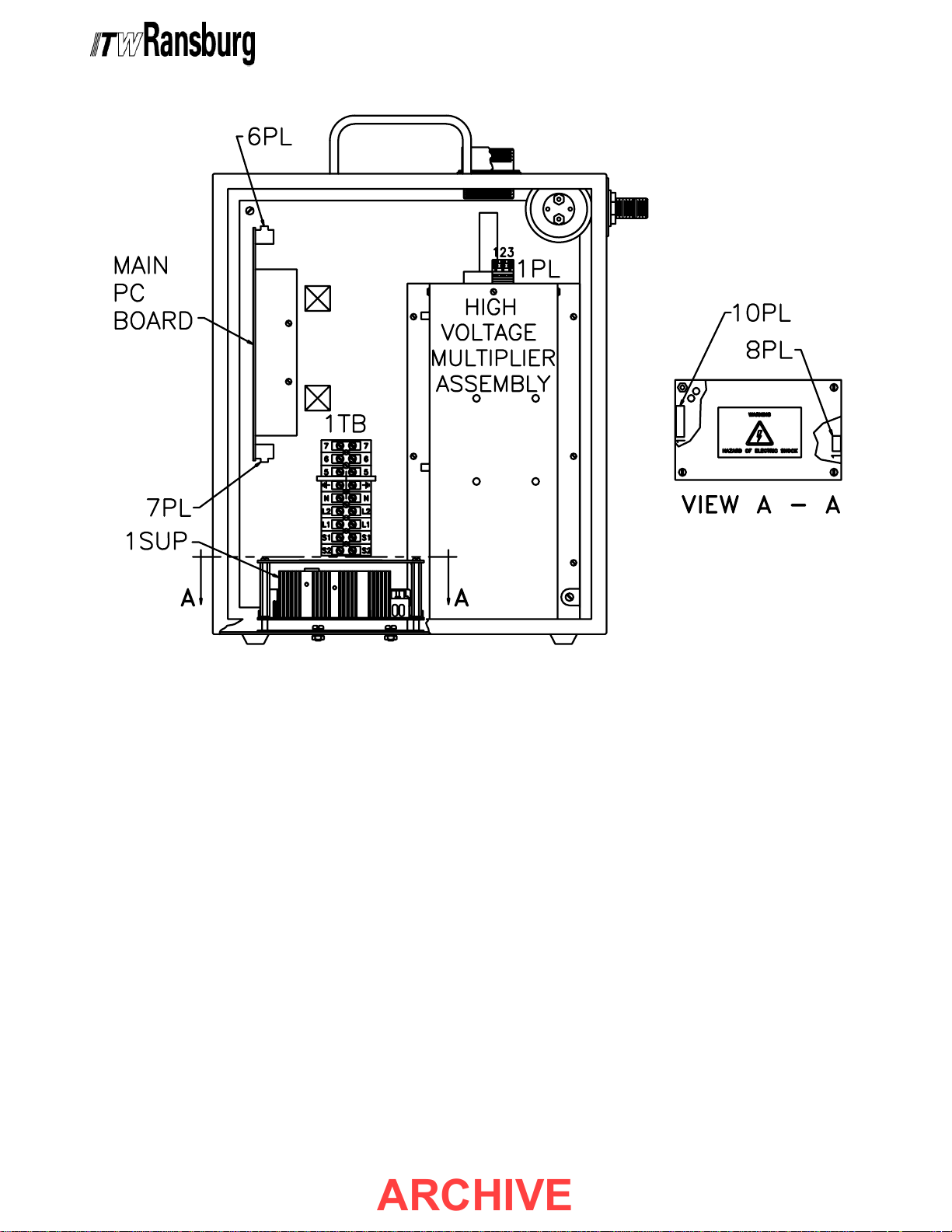
9040 Classic for REA & M90 Systems - Maintenance
ARCHIVE
Figure 9: Troubleshooting DiagramFigure 9: Troubleshooting Diagram
Figure 9: Troubleshooting Diagram
Figure 9: Troubleshooting DiagramFigure 9: Troubleshooting Diagram
CP-97-02.5
3232
32
3232
Page 36
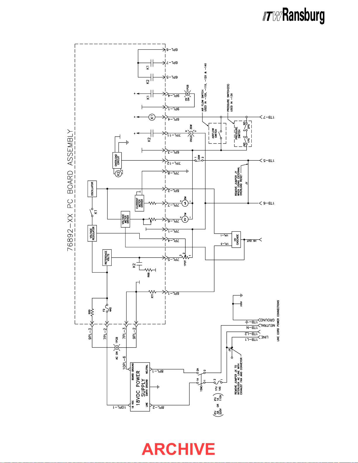
9040 Classic for REA & M90 Systems - Maintenance
ARCHIVE
3333
33
3333
Figure 10: 9040 Classic Power Supply Block DiagramFigure 10: 9040 Classic Power Supply Block Diagram
Figure 10: 9040 Classic Power Supply Block Diagram
Figure 10: 9040 Classic Power Supply Block DiagramFigure 10: 9040 Classic Power Supply Block Diagram
CP-97-02.5
Page 37

9040 Classic for REA & M90 Systems - Maintenance
ARCHIVE
NOTESNOTES
NOTES
NOTESNOTES
CP-97-02.5
3434
34
3434
Page 38
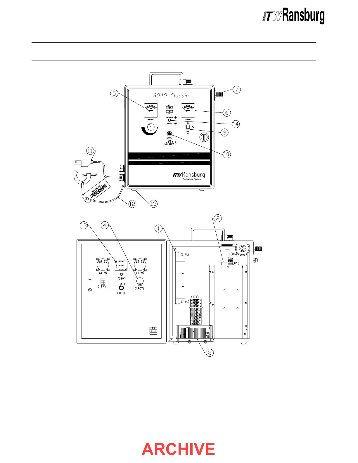
9040 Classic for REA & M90 Systems - Parts Identification
ARCHIVE
PP
P
PP
ARAR
AR
ARAR
TS IDENTIFICATS IDENTIFICA
TS IDENTIFICA
TS IDENTIFICATS IDENTIFICA
TIONTION
TION
TIONTION
3535
35
3535
Figure 11: 9040 Classic for REA and M90 - Parts DiagramFigure 11: 9040 Classic for REA and M90 - Parts Diagram
Figure 11: 9040 Classic for REA and M90 - Parts Diagram
Figure 11: 9040 Classic for REA and M90 - Parts DiagramFigure 11: 9040 Classic for REA and M90 - Parts Diagram
CP-97-02.5
Page 39
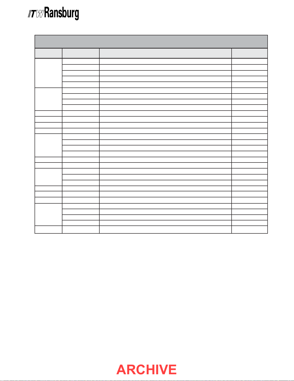
9040 Classic for REA & M90 Systems - Parts Identification
ARCHIVE
9040 CLASSIC for REA9040 CLASSIC for REA
9040 CLASSIC for REA
9040 CLASSIC for REA9040 CLASSIC for REA
Item #Item #
Item #
Item #Item #
1
2
3 76434-01 ON/OFF Switch 1SW
4 70556-03 High Voltage Adjust Potentiometer 1POT
5 76436-91 Kilovolt (kV) Meter 1M
6 76436-92 Microamp (μA) Meter 2M
7
8 75337-05 Power Supply, 18 VDC 1SUP
9 LSME0082-04 Fuse, PC Board, Slow Blow, 4 Amp F2
10
11 6262-00 AC Line Cord
12 70539-00 Ground Wire Assembly
13 76455-02 LED Display Board
14
15 5627-00 Rubber Feet
Part #Part #
Part #
Part #Part #
76892-10 For 76447-10X, REA-IV Applicator (70404)
76892-12 For 76447-12X, REA-III Applicator (70929, 72316)
76892-13 For 76447-13X, REA-III Automatic (70393)
76892-15 For 76447-14X, M90 Classic Applicator (77132)
76304-02 For 76447-10X, 65kV
76304-07 For 76447-14X, 85kV
76304-01 For 76447-12X and 76447-13X, 90kV
13742-01 For 76447-10X and 76447-12X
13742-02 For 76447-14X
25766-106 Pressure Switch for 76447-13X 1PS, 2PS
72771-06 Slow Blow, 1 Amp, 110-120 VAC Input 1FU
72771-01 Slow Blow, 0.5 Amp, 220-240 VAC Input 1FU
76442-01 Reset Switch, Normally Closed
76441-00 Lens, Yellow
76443-01 Bulb
& M90 - P & M90 - P
& M90 - P
& M90 - P & M90 - P
DescriptionDescription
Description
DescriptionDescription
PC Board and Heat Sink Assembly:PC Board and Heat Sink Assembly:
PC Board and Heat Sink Assembly:
PC Board and Heat Sink Assembly:PC Board and Heat Sink Assembly:
High Voltage Multiplier (Oil-Filled):High Voltage Multiplier (Oil-Filled):
High Voltage Multiplier (Oil-Filled):
High Voltage Multiplier (Oil-Filled):High Voltage Multiplier (Oil-Filled):
Air Flow Switch Assembly:Air Flow Switch Assembly:
Air Flow Switch Assembly: 1FS
Air Flow Switch Assembly:Air Flow Switch Assembly:
Fuse, Front Panel:Fuse, Front Panel:
Fuse, Front Panel:
Fuse, Front Panel:Fuse, Front Panel:
Overload Indicator and Reset Switch Assembly:Overload Indicator and Reset Switch Assembly:
Overload Indicator and Reset Switch Assembly:
Overload Indicator and Reset Switch Assembly:Overload Indicator and Reset Switch Assembly:
ARAR
TS LISTTS LIST
AR
TS LIST
ARAR
TS LISTTS LIST
(Figure 1 (Figure 1
(Figure 1
(Figure 1 (Figure 1
1)1)
1)
1)1)
NotationNotation
Notation
NotationNotation
CP-97-02.5
3636
36
3636
Page 40
9040 Classic for REA & M90 Systems - Parts Identification
ARCHIVE
9040 CLASSIC for REA9040 CLASSIC for REA
9040 CLASSIC for REA
9040 CLASSIC for REA9040 CLASSIC for REA
DescriptionDescription
Description
DescriptionDescription
Fuse, Front Panel
Deluxe Test Kit
Test Resistor
Fuse, PC Board
PC Board Assembly,
REA-IV Hand
PC Board Assembly,
REA-III Hand
PC Board Assembly,
REA-III Auto
PC Board Assembly,
M90 Classic
High Voltage Multiplier
High Voltage Multiplier
High Voltage Multiplier
Power Supply Tester
Part #Part #
Part #
Part #Part #
72771-06
76652-04
16688-01
LSME0082-04
76892-10
76892-12
76892-13
76892-15
76304-01
76304-02
76304-07
LTST5000-00
& M90 - RECOMMENDED SP & M90 - RECOMMENDED SP
& M90 - RECOMMENDED SP
& M90 - RECOMMENDED SP & M90 - RECOMMENDED SP
No. of ApplicatorsNo. of Applicators
No. of Applicators
No. of ApplicatorsNo. of Applicators
1
1
1
2
1
1
1
1
1
1
1
1
1
1
1
4
1
1
1
1
1
1
1
1
2
1
1
6
1
1
1
1
1
1
1
1
2
1
For Troubleshooting
1
For Troubleshooting
8
2
2
2
2
1
1
1
1
For 76447-12 & -13
For Troubleshooting
ARE PARE P
ARE P
ARE PARE P
Purposes Only
Purposes Only
For 76447-10
For 76447-12
For 76447-13
For 76447-14
For 76447-10
For 76447-14
Purposes Only
ARAR
AR
ARAR
NotesNotes
Notes
NotesNotes
TSTS
TS
TSTS
9040 CLASSIC for REA & M90 - ACCESSORIES9040 CLASSIC for REA & M90 - ACCESSORIES
9040 CLASSIC for REA & M90 - ACCESSORIES
9040 CLASSIC for REA & M90 - ACCESSORIES9040 CLASSIC for REA & M90 - ACCESSORIES
DescriptionDescription
Description
DescriptionDescription
Control Unit/Power Supply Test Assembly
High Voltage Test Probe and Meter
Current/SCI Meter
Deluxe Meter Kit (Includes 76652-01, 76652-02, and Paint Meter)
Test Resistor
Part #Part #
Part #
Part #Part #
LTST5000-00
76652-01
76652-02
76652-04
16688-01
3737
37
3737
CP-97-02.5
Page 41

9040 Classic for REA & M90 Systems - Parts Identification
ARCHIVE
NOTESNOTES
NOTES
NOTESNOTES
CP-97-02.5
3838
38
3838
Page 42

9040 Classic for REA & M90 Systems - Warranty Policies
ARCHIVE
WW
ARRANTYARRANTY
W
ARRANTY
WW
ARRANTYARRANTY
LIMITED WLIMITED W
LIMITED W
LIMITED WLIMITED W
ITW Ransburg will replace or repair without charge
any part and/or equipment that falls within the
specified time (see below) because of faulty
workmanship or material, provided that the
equipment has been used and maintained in
accordance with ITW Ransburg's written safety
and operating instructions, and has been used
under normal operating conditions. Normal wear
items are excluded.
THE USE OF OTHER THAN ITW RANS-THE USE OF OTHER THAN ITW RANS-
THE USE OF OTHER THAN ITW RANS-
THE USE OF OTHER THAN ITW RANS-THE USE OF OTHER THAN ITW RANSBURG APPROVED PARTS, VOID ALLBURG APPROVED PARTS, VOID ALL
BURG APPROVED PARTS, VOID ALL
BURG APPROVED PARTS, VOID ALLBURG APPROVED PARTS, VOID ALL
WARRANTIES.WARRANTIES.
WARRANTIES.
WARRANTIES.WARRANTIES.
ARRANTYARRANTY
ARRANTY
ARRANTYARRANTY
POLICIES POLICIES
POLICIES
POLICIES POLICIES
ITW RANSBURG'S ONLY OBLIGATIONITW RANSBURG'S ONLY OBLIGATION
ITW RANSBURG'S ONLY OBLIGATION
ITW RANSBURG'S ONLY OBLIGATIONITW RANSBURG'S ONLY OBLIGATION
UNDER THIS WARRANTY IS TO REPLACEUNDER THIS WARRANTY IS TO REPLACE
UNDER THIS WARRANTY IS TO REPLACE
UNDER THIS WARRANTY IS TO REPLACEUNDER THIS WARRANTY IS TO REPLACE
PARTS THAT HAVE FAILED BECAUSEPARTS THAT HAVE FAILED BECAUSE
PARTS THAT HAVE FAILED BECAUSE
PARTS THAT HAVE FAILED BECAUSEPARTS THAT HAVE FAILED BECAUSE
OF FAULTY WORKMANSHIP OR MATER-OF FAULTY WORKMANSHIP OR MATER-
OF FAULTY WORKMANSHIP OR MATER-
OF FAULTY WORKMANSHIP OR MATER-OF FAULTY WORKMANSHIP OR MATERIALS. THERE ARE NO IMPLIED WARRAN-IALS. THERE ARE NO IMPLIED WARRAN-
IALS. THERE ARE NO IMPLIED WARRAN-
IALS. THERE ARE NO IMPLIED WARRAN-IALS. THERE ARE NO IMPLIED WARRANTIES NOR WARRANTIES OF EITHERTIES NOR WARRANTIES OF EITHER
TIES NOR WARRANTIES OF EITHER
TIES NOR WARRANTIES OF EITHERTIES NOR WARRANTIES OF EITHER
MERCHANTABILITY OR FITNESS FOR AMERCHANTABILITY OR FITNESS FOR A
MERCHANTABILITY OR FITNESS FOR A
MERCHANTABILITY OR FITNESS FOR AMERCHANTABILITY OR FITNESS FOR A
PARTICULAR PURPOSE. ITW RANS-PARTICULAR PURPOSE. ITW RANS-
PARTICULAR PURPOSE. ITW RANS-
PARTICULAR PURPOSE. ITW RANS-PARTICULAR PURPOSE. ITW RANSBURG ASSUMES NO LIABILITY FORBURG ASSUMES NO LIABILITY FOR
BURG ASSUMES NO LIABILITY FOR
BURG ASSUMES NO LIABILITY FORBURG ASSUMES NO LIABILITY FOR
INJURY, DAMAGE TO PROPERTY ORINJURY, DAMAGE TO PROPERTY OR
INJURY, DAMAGE TO PROPERTY OR
INJURY, DAMAGE TO PROPERTY ORINJURY, DAMAGE TO PROPERTY OR
FOR CONSEQUENTIAL DAMAGES FORFOR CONSEQUENTIAL DAMAGES FOR
FOR CONSEQUENTIAL DAMAGES FOR
FOR CONSEQUENTIAL DAMAGES FORFOR CONSEQUENTIAL DAMAGES FOR
LOSS OF GOODWILL OR PRODUCTIONLOSS OF GOODWILL OR PRODUCTION
LOSS OF GOODWILL OR PRODUCTION
LOSS OF GOODWILL OR PRODUCTIONLOSS OF GOODWILL OR PRODUCTION
OR INCOME, WHICH RESULT FROM USEOR INCOME, WHICH RESULT FROM USE
OR INCOME, WHICH RESULT FROM USE
OR INCOME, WHICH RESULT FROM USEOR INCOME, WHICH RESULT FROM USE
OR MISUSE OF THE EQUIPMENT BYOR MISUSE OF THE EQUIPMENT BY
OR MISUSE OF THE EQUIPMENT BY
OR MISUSE OF THE EQUIPMENT BYOR MISUSE OF THE EQUIPMENT BY
PURCHASER OR OTHERS.PURCHASER OR OTHERS.
PURCHASER OR OTHERS.
PURCHASER OR OTHERS.PURCHASER OR OTHERS.
SPARE PARTS: One hundred and eighty (180)
days from date of purchase, except for rebuilt
parts (any part number ending in "R") for which the
warranty period is ninety (90) days.
EQUIPMENT: When purchased as a complete
unit, (i.e., guns, power supplies, control units,
etc.), is one (1) year from date of purchase.
WRAPPING THE APPLICATOR, ASSO-WRAPPING THE APPLICATOR, ASSO-
WRAPPING THE APPLICATOR, ASSO-
WRAPPING THE APPLICATOR, ASSO-WRAPPING THE APPLICATOR, ASSOCIATED VALVES AND TUBING, ANDCIATED VALVES AND TUBING, AND
CIATED VALVES AND TUBING, AND
CIATED VALVES AND TUBING, ANDCIATED VALVES AND TUBING, AND
SUPPORTING HARDWARE IN PLASTIC,SUPPORTING HARDWARE IN PLASTIC,
SUPPORTING HARDWARE IN PLASTIC,
SUPPORTING HARDWARE IN PLASTIC,SUPPORTING HARDWARE IN PLASTIC,
SHRINK-WRAP, OR ANY OTHER NON-SHRINK-WRAP, OR ANY OTHER NON-
SHRINK-WRAP, OR ANY OTHER NON-
SHRINK-WRAP, OR ANY OTHER NON-SHRINK-WRAP, OR ANY OTHER NONAPPROVED COVERING, WILL VOID THISAPPROVED COVERING, WILL VOID THIS
APPROVED COVERING, WILL VOID THIS
APPROVED COVERING, WILL VOID THISAPPROVED COVERING, WILL VOID THIS
WARRANTY.WARRANTY.
WARRANTY.
WARRANTY.WARRANTY.
FLUID HANDLING: One (1) year from date of
purchase (i.e., Totalizer, CCV Valves, etc.).
AIR BEARING ROTATORS: Fifteen thousand
(15,000) hours or three (3) years, whichever occurs
first. Warranty period begins on the date of
purchase.
EXCLUSIONS:EXCLUSIONS:
EXCLUSIONS:
EXCLUSIONS:EXCLUSIONS:
If, in ITW Ransburg's opinion the warranty item in
question, or other items damaged by this part was
improperly installed, operated or maintained, ITW
Ransburg will assume no responsibility for repair
or replacement of the item or items. The purchaser,
therefore will assume all responsibility for any cost
of repair or replacement and service related costs
if applicable.
3939
39
3939
CP-97-02.5
Page 43
MANUALMANUAL
ARCHIVE
MANUAL
MANUALMANUAL
This manual was published to replace Service
Manual
Power Supply for the REA/REM/M90 Classic
Coating Systems, to make the following changes:
1. Added " " to the "Front Cover".
2. Added "Atex" section.
CP-97-02.4,CP-97-02.4,
CP-97-02.4,
CP-97-02.4,CP-97-02.4,
9040 Classic High Voltage
CHANGE SUMMAR CHANGE SUMMAR
CHANGE SUMMAR
CHANGE SUMMAR CHANGE SUMMAR
YY
Y
YY
CP-97-02.5
Page 44

Service Manual Price:Service Manual Price:
ARCHIVE
Service Manual Price: €
Service Manual Price:Service Manual Price:
ManufacturingManufacturing
Manufacturing
ManufacturingManufacturing
1910 North Wayne Street
Angola, Indiana 46703-9100
Telephone: 260/665-8800
Fax: 260/665-8516
Technical/Service AssistanceTechnical/Service Assistance
Technical/Service Assistance
Technical/Service AssistanceTechnical/Service Assistance
Automotive Assembly and Tier I Telephone: 800/ 626-3565 Fax: 419/ 470-2040
Industrial Systems Telephone: 800/ 233-3366 Fax: 419/ 470-2071
Ransburg Guns Telephone: 800/ 233-3366 Fax: 419/ 470-2071
www.itwransburg.com
25.00 (Euro)25.00 (Euro)
25.00 (Euro)
25.00 (Euro)25.00 (Euro)
$30.00 (U.S.)$30.00 (U.S.)
$30.00 (U.S.)
$30.00 (U.S.)$30.00 (U.S.)
Technical Support Representative will direct you to the appropriate telephone numberTechnical Support Representative will direct you to the appropriate telephone number
Technical Support Representative will direct you to the appropriate telephone number
Technical Support Representative will direct you to the appropriate telephone numberTechnical Support Representative will direct you to the appropriate telephone number
for ordering Spare Parts.for ordering Spare Parts.
for ordering Spare Parts.
for ordering Spare Parts.for ordering Spare Parts.
© 2008 Illinois Tool Works Inc. All rights reserved.
Models and specifications subject to change without notice.
Form No. CP-97-02.5
Litho in U.S.A.
05/08
 Loading...