


 Loading...
SERVICE MANUAL
LN-9400-00.9
(Replaced LN-9400-00.8)
December 2012
DYNAFLOWTM USER MANUAL
MODEL: 77376 and A12233
IMPORTANT: Before using this equipment, carefully read SAFETY PRECAUTIONS, starting on page 1, and all instructions in this manual. Keep this Service Manual for future reference.
Service Manual Price: $50.00 (U.S.)

NOTE: This manual has been changed from revision LN-9400-00.8 to revision LN-9400-00.9 Reasons for this change are noted under “Manual Change Summary” inside the back
cover of this manual.
LN-9400-00.9

DynaFlowTM User Manual - Contents
CONTENTS |
|
|
PAGE |
SAFETY: |
1-5 |
SAFETY PRECAUTIONS......................................................................................... |
|
|
1 |
HAZARDS / SAFEGUARDS.............................................................................................. |
|
|
2-5 |
INTRODUCTION: |
6-13 |
FEATURES........................................................................................................................ |
6 |
DESCRIPTION................................................................................................................. |
6-9 |
BLOCK DIAGRAM............................................................................................................. |
10 |
DYNAFLOW SPECIFICATIONS................................................................................... |
11-13 |
INSTALLATION: |
14-27 |
SYSTEM GUIDELINES, EQUIPMENT GROUNDING, LOCATIONS, MOUNTING............. |
14-15 |
BLOCK DIAGRAM FOR A SINGLE-COMPONENT GUN................................................ |
16 |
BLOCK DIAGRAM FOR A TWO-COMPONENT GUN............................................................. |
17 |
BLOCK DIAGRAM FOR A THREE-COMPONENT GUN......................................................... |
18 |
INPUT POWER............................................................................................................. |
19 |
INTERFACING TO THE FLOW CONTROLLER........................................................ |
20-23 |
MOTHER BOARD TERMINALS, HARDWARECONFIGURATION, TRANSDUCERS......... |
24-26 |
OPERATION: |
28-61 |
OVERVIEW..................................................................................................................... |
28-29 |
PARAMETER DESCRIPTIONS......................................................................................... |
30-43 |
AUTOMATIC GUN APPLICATIONS................................................................................. |
44-45 |
MANUAL HAND GUN APPLICATIONS............................................................................. |
45-46 |
GENERAL........................................................................................................................ |
46-47 |
JOB SELECT TIMING DIAGRAM.................................................................................. |
48-49 |
JOB SELECT TIMING DIAGRAM SAMPLE, JOB QUEUE, REVERSE FLOW................. |
50-54 |
PROCEDURES, FIRST TIME STARTUP, NORMAL STARTUP.......................... |
54-56 |
PID CONTROL........................................................................................................ |
56-61 |
MAINTENANCE: |
62-87 |
TROUBLESHOOTING...................................................................................................... |
62-71 |
SYSTEM PREVENTIVE MAINTENANCE INSTRUCTIONS............................................ |
71 |
SYSTEM COMPONENTS AND PARTS IDENTIFICATION........................................... |
72 |
RECOMMENDED SPARE PARTS................................................................................ |
73-74 |
HARDWARE SETTINGS................................................................................................ |
75-78 |
NEW CHANNEL CARD JUMPERS........................................................................... |
79-80 |
INTERFACE MODULE DIP SETTINGS................................................................. |
81 |
CONTROL RACK TERMINAL IDENTIFICATION...................................................... |
82-85 |
SERIAL COMMUNICATION PROTOCOLS................................................................ |
86 |
RATIO CONVERSION...................................................................................... |
87 |
WARRANTY POLICIES: |
88 |
LIMITED WARRANTY.............................................................................................. |
88 |
(Continued Next Page) |
|
LN-9400-00.9

DynaFlowTM User Manual - Contents
CONTENTS (Cont.) |
|
|
PAGE |
APPENDIX: |
89-93 |
ADDENDUM A.................................................................................................................... |
89-90 |
ADDENDUM B.................................................................................................................. |
91-92 |
ADDENDUM C................................................................................................................ |
93 |
LN-9400-00.9
DynaFlowTM User Manual - Safety
SAFETY
SAFETY PRECAUTIONS
Before operating, maintaining or servicing any Ransburg electrostatic coating system, read and understand all of the technical and safety literature for your Ransburg products. This manual contains information that is important for you to know and understand. This information relates to USER SAFETYand PREVENTING EQUIPMENT PROBLEMS. To help you recognize this information, we use the following symbols. Please pay particular attention to these sections.
A WARNING! states information to alert you to a situation that might cause serious injury if instructions are not followed.
A CAUTION! states information that tells how to prevent damage to equipment or how to avoid a situation that might cause minor injury.
A NOTE is information relevant to the procedure in progress.
While this manual lists standard specifications and service procedures, some minor deviations may be found between this literature and your equipment. Differences in local codes and plant requirements, material delivery requirements, etc., make such variations inevitable. Compare this manual with your system installation drawings and appropriate Ransburg equipment manuals to reconcile such differences.
Careful study and continued use of this manual will provide a better understanding of the equipment and process, resulting in more efficient operation, longer trouble-free service and faster, easier troubleshooting. If you do not have the manuals and safety literature for your Ransburg system, contact your local Ransburg representative or Ransburg.
!W A R N I N G
The user MUST read and be familiar with the Safety Section in this manual and the
Ransburg safety literature therein identified.
This manual MUST be read and thoroughly understood by ALL personnel who operate, clean or maintain this equipment! Special care should be taken to ensure that the WARNINGS and safety requirements for operating and servicing the equipment are followed. The user should be aware of and adhere to ALL local building and fire codes and ordinances as well as NFPA-33 SAFETY STANDARD, LATEST EDITION, prior to installing, operating, and/or servicing this equipment.
!W A R N I N G
The hazards shown on the following page may occur during the normal use of this equipment. Please read the hazard chart beginning on page 2.
LN-9400-00.9 |
1 |

DynaFlowTM User Manual - Safety
AREA |
HAZARD |
SAFEGUARDS |
Tells where hazards |
Tells what the hazard is. |
Tells how to avoid the hazard. |
may occur. |
|
|
|
|
|
Spray Area |
Fire Hazard |
Fire extinguishing equipment must be present in the |
|
Improperorinadequateopera-tion |
spray area and tested periodically. |
|
|
|
|
and maintenance procedures will |
Spray areas must be kept clean to prevent the ac- |
|
cause a fire hazard. |
cumulation of combustible residues. |
|
Protection against inadvertent |
Smoking must never be allowed in the spray area. |
|
arcing that is capable of causing |
|
|
fireorexplosionislostifanysafety |
The high voltage supplied to the atomizer must be |
|
interlocks are disabled during op- |
turnedoffpriortocleaning,flushingormaintenance. |
|
eration. Frequent power supply |
|
|
shutdown indicates a problem in |
When using solvents for cleaning: |
|
the system requiring correction. |
Thoseusedforequipmentflushingshouldhaveflash |
|
|
|
|
|
points equal to or higher than those of the coating |
|
|
material. |
|
|
Those used for general cleaning must have flash |
|
|
points above 100oF (37.8oC). |
|
|
Spray booth ventilation must be kept at the rates |
|
|
required by NFPA-33, OSHA, and local codes. In ad- |
|
|
dition, ventilation must be maintained during cleaning |
|
|
operationsusingflammableorcombustiblesolvents. |
|
|
Electrostatic arcing must be prevented. |
|
|
Test only in areas free of combustible material. |
|
|
Testing may require high voltage to be on, but only |
|
|
as instructed. |
|
|
Non-factory replacement parts or unauthorized |
|
|
equipment modifications may cause fire or injury. |
|
|
If used, the key switch bypass is intended for use |
|
|
only during setup operations. Production should |
|
|
never be done with safety interlocks disabled. |
|
|
Never use equipment intended for use in waterborne |
|
|
installations to spray solvent based materials. |
|
|
The paint process and equipment should be set up |
|
|
and operated in accordance with NFPA-33, NEC, |
|
|
and OSHA requirements. |
|
|
|
2 |
LN-9400-00.9 |

DynaFlowTM User Manual - Safety
AREA |
HAZARD |
SAFEGUARDS |
Tells where hazards |
Tells what the hazard is. |
Tells how to avoid the hazard. |
may occur. |
|
|
|
|
|
General Use and |
Improper operation or mainte- |
Personnel must be given training in accordance with |
Maintenance |
nance may create a hazard. |
the requirements of NFPA-33. |
|
Personnel must be properly |
Instructions and safety precautions must be read |
|
trained in the use of this equip- |
and understood prior to using this equipment. |
|
ment. |
Comply with appropriate local, state, and national |
|
|
|
|
|
codes governing ventilation, fire protection, opera- |
|
|
tion maintenance, and housekeeping. Reference |
|
|
OSHA, NFPA33, and your insurance company |
|
|
requirements. |
|
|
|
Electrical |
High voltage equipment is utilized. |
The power supply, optional remote control cabinet, |
Equipment |
Arcing in areas of flammable or |
and all other electrical equipment must be located |
|
combustible materials may oc- |
outside Class I or II, Division 1 and 2 hazardous |
|
cur. Personnel are exposed to |
areas refer to NFPA-33. |
|
high voltage during operation and |
|
|
maintenance. |
Turn the power supply OFF before working on the |
|
Protection against inadvertent |
equipment. |
|
|
|
|
arcing that may cause a fire or |
Test only in areas free of flammable or combustible |
|
explosion is lost if safety circuits |
material. |
|
are disabled during operation. |
Testing may require high voltage to be on, but only |
|
|
|
|
Frequent power supply shut-down |
as instructed. |
|
indicates a problem in the system |
|
|
which requires correction. |
Production should never be done with the safety |
|
An electrical arc can ignite coat- |
circuits disabled. |
|
|
|
|
ing materials and cause a fire or |
Before turning the high voltage on, make sure no |
|
explosion. |
objects are within the sparking distance. |
|
|
|
Explosion Hazard/ |
Halogenated hydrocarbon sol- |
Aluminum is widely used in other spray application |
Incompatible |
vents for example: methylene |
equipment - such as material pumps, regulators, |
Materials |
chloride and 1,1,1,-Trichloroeth- |
triggering valves, etc. Halogenated hydrocarbon |
|
ane are not chemically compatible |
solvents must never be used with aluminum equip- |
|
with the aluminum that might be |
ment during spraying, flushing, or cleaning. Read |
|
usedinmanysystemcomponents. |
the label or data sheet for the material you intend to |
|
The chemical reaction caused by |
spray. If in doubt as to whether or not a coating or |
|
these solvents reacting with alu- |
cleaning material is compatible, contact your mate- |
|
minum can become violent and |
rial supplier. Any other type of solvent may be used |
|
lead to an equipment explosion. |
with aluminum equipment. |
|
|
|
LN-9400-00.9 |
3 |

DynaFlowTM User Manual - Safety
AREA |
HAZARD |
SAFEGUARDS |
Tells where hazards |
Tells what the hazard is. |
Tells how to avoid the hazard. |
may occur. |
|
|
Toxic Substances |
|
|
Toxic Substances |
Certain material may be harmful |
Follow the requirements of the Material Safety Data |
|
if inhaled, or if there is contact |
Sheet supplied by coating material manufacturer. |
|
with the skin. |
Adequate exhaust must be provided to keep the air |
|
|
|
|
|
free of accumulations of toxic materials. |
|
|
Use a mask or respirator whenever there is a chance |
|
|
of inhaling sprayed materials. The mask must be |
|
|
compatible with the material being sprayed and its |
|
|
concentration. Equipment must be as prescribed |
|
|
by an industrial hygienist or safety expert, and be |
|
|
NIOSH approved. |
|
|
|
4 |
LN-9400-00.9 |

DynaFlowTM User Manual - Safety
NOTES
LN-9400-00.9 |
5 |
DynaFlowTM User Manual - Introduction
INTRODUCTION
FEATURES
•Configurable operating parameters (JOBs) which can be saved and recalled on demand.
•Graphic diagnostics for troubleshooting and for achieving maximum system performance.
•Comprehensive help information easily viewed on the OPERATOR INTERFACE.
•Configurable manual and/or automatic GUN applications.
•Dynamic analog fluid control – the control of flow rate while running a JOB.
•Reverse fluid flow detection provides added protection for system components.
NOTE
This feature requires flow meters that provide reverse flow output.
•Pot-life timer alarms.
•Local and remote monitoring and control.
•Discrete PLC interface capability for remote control.
•Remote I/O (RIO) communications link for direct connection to Allen-Bradley PLCs.
•Process and configuration error and fault detection and reporting.
description
The ability to control the delivery of material greatly increases the overall efficiency of the spray operating system and results directly in more uniform andconsistentpaintfinishqualityandreducesthe amount of material waste. The ability of the fluid flowcontrollertorespondwithquick,concise,and repeatable control maximizes finish quality and minimizes material waste.
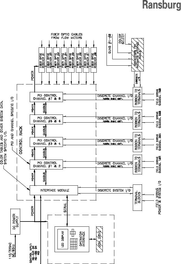
The DynaFlowTM Flow Controller design utilizes a form of distributed processing similar to many of the industrial network architectures available today.Theentiretaskoffluidflowcontrolisbroken up into parts. Each portion of the system is designedforaspecificpurpose.Sinceeachelement of the system is performing specialized functions, and all elements are operating at the same time, overall performance of the system is enhanced. Functionality of the control system components is as follows:
Channel Module
The Channel Module represents the core of the system. Each Channel Module is responsible for:
•Monitoring the CHANNEL specific inputs and supplying the necessary CHANNEL specific outputs for control and status.
•Receiving and processing the flow meter feedback pulses.
•Determining the analog PID output control signal by performing high-speed floatingpoint math.
•USB memory stick, backup of configuration and operational data.
•Versatile system integration.
•Easy to use.
•Help text and troubleshooting guide available on screens.
•Receiving and interpreting commands from the Interface Module through high speed Ransburg CAN Bus communication.
•Supplying data and status upon request to and from the Interface Module.
6 |
LN-9400-00.9 |
DynaFlowTM User Manual - Introduction
Located on the front panel of the Channel Module are several status indicator lights (LEDs). These are:
1.CPU - Is ON when the microprocessor is operating normally.
2.ACTIVE - Is ON when communication is taking place to the Interface Module.
3.FAULT - Is ON when there is a problem with the module.
Interface Module
The Interface Module performs the following:
•Stores system configuration and data tables.
•Acts as an interpreter for communication with an external Host computer, PLC and/ or the local Operator Interface. Communicates through a high speed Ransburg CAN Bus data link to each Channel Module.
•Responsible for system specific inputs and supplying the necessary system specific outputs for control and status.
Located on the front panel of the Interface Module are several status indicator lights (LEDs). These are:
1.CPU - Is ON when the microprocessor is operating normally.
2.ACTIVE - Is ON when RIO communication is taking place to an Allen-Bradley PLC.
3.FAULT - Is ON when there is a problem with the module.
Local Operator Interface
Supplied as part of the DynaFlow Stand-Alone Control Cabinet, Model# 77376 and A12233.
•Permits total control of the system.
•Displays system configuration and data to the operator.
•Computes and displays text and graphic diagnostic information.
•Organizes, formats, and reports all data and configuration tables.
The DynaFlow fluid flow control system achieves real-time closed loop control through the use of CHANNELs and GUNs. A CHANNEL consists of an electrical-to-pneumatic (E/P) transducer, material regulator and fluid flow meter combination through which a single material is controlled. A GUN represents a single applicator through which one or more materials are delivered. One ormoreCHANNELsareconfiguredforeachGUN.
Two-component delivery systems (referred to as 2K systems) have two CHANNELs assigned to a single GUN. The materials are statically mixed before being delivered to the GUN.
Each CHANNEL operates independently of, and simultaneously with all the other CHANNELs.This lets the DynaFlow controller provide accurate dynamic regulation for each CHANNEL, regard-less of minor system wear or changes in system variables. With a single-component coating material, the DynaFlow controller detects changes from the programmed flow rate and adjusts the output to correct it. With two-component coatings (where both the resin and catalyst are regulated and monitored), the DynaFlow controller detects any change in the total flow and makes the required adjustments to maintain the programmed flow and ratio. This holds the flow rates of the coating components constant. Deviations from the desired mixratioarealsoimmediatelycorrectedusingthis same closed loop process.
A detailed guide on PID control is supplied in this manual to assist you should you want to adjust the control parameters.There are many additional features included in the DynaFlow Fluid Flow Control which reflect on the many years of experience accumulated by Ransburg.
The control rack and OPERATOR INTERFACE panels are consistent with and easily integrated with other Ransburg control products into larger custom system control panels. This optimizes costs, space and functionality for control of multiple applicator spray stations. Spray stations may also
LN-9400-00.9 |
7 |

DynaFlowTM User Manual - Introduction
incorporate rotary atomizer speed control, shaping air, high voltage power supplies and more.
The standard stand-alone control cabinet includes control of up to 8 CHANNELs. It incorporates an integrated 15" color LCD touch screen, PC based display/interface sub-panel.
Configurable Operating
Parameters
The design of the DynaFlow system allows it to be configured to meet the specific requirements of each application. The 8 available CHANNELs can be linked together, using 1 of 8 GUNs, to control the flow and mixing regulation of twocomponent materials. The installed channels can be configured to suit the application. If you are using single-component coatings, the DynaFlow controller can support 8 separate single CHANNEL GUNs operating simultaneously. If you are using two-component materials, then 4 separate 2-CHANNEL GUNs operating simultaneously can be supported. For example, you can use 4
CHANNELs assigned to 2 GUNs to spray 2 dual component paints on automatic machines, and 2 CHANNELs assigned to 1 GUN to spray one dual component paint with a manual hand spray GUN.
In addition to the above, a GUN configured for two-component operation can be dynamically changed to operate in a single-component mode by simply setting the ratio JOB parameter to 100. This allows a GUN to operate in either dual or single-component modes by simply changing JOB numbers.
The controlling parameters for each GUN and the CHANNEL(S) assigned to that GUN, are called
JOBs.The JOB values define flow characteristics such as Target Flow Rate, Mix Ratio, Flow Tolerance, etc. JOBs include all of the parameters that may be dependent on the material used.This offers the ability to optimize system control as needed per material and then recall the settings each time that material is requested. There are up to 100 JOB #s for each GUN. By saving frequently used JOB #s to memory you can later recall them by loading the number representing that JOB #. All of the JOB #s can be backed-up to, and restored fromaUSBmemorydevice.Referencethe"Opera-
tor Interface Users Manual" and "Program-mers Manual" for details on data transfer operation and available formats.
TheflowcontrolunitincludesoneInterfaceModule and up to 8 hardware PID control CHANNELs, 2 CHANNELs located on each of the 4 possible Channel Modules. The Interface Module will communicate to a host controller. The host is one of the following:
•PLC using discrete I/O
•Allen-Bradley PLC using RIO
•Local Operator Interface using an RS232C communication port
3-K Operation
DynaFlow was designed for either single or two- componentoperation.Three-componentoperation is possible by configuring two, two-component, guns. The first Gun is set up as follows:
Gun 1 =
Master Channel =
Material = Resin
Flow Controller = Color Change
Value (CCV)
Flow Meter = Standard Gear-Type
Slave Channel =
Material = 2nd Component
Flow Controller = MVR, with appropriate size needle
Flow Meter = Piston or Gear, depending on min/max flow rates
(see Notes 4 and 5) Operating Mode = Manual
8 |
LN-9400-00.9 |

The output of the first Gun is then fed into the
Master Channel input of the second Gun. The second Gun is setup as follows:
Gun 2 =
Master Channel =
Material = Output of Gun 1 (Resin + 2nd
Component)
Flow Controller = Color Change Value
(CCV)
(see Notes 1, 2, and 3)
Flow Meter = Gear-Type
Slave Channel =
Material = 3rd Component
Flow Controller = MVR, with appropriate size needle
Flow Meter = Piston or Gear, depending on min/max flow rates
(see Notes 4 and 5) Operating Mode = Manual or Auto
(see Notes 1, 2, and 3)
NOTES:
1.If the output of Gun 2 supplies one or more hand guns, then Gun 2 should be operated in Manual mode using a CCV for the Master
Channel flow controller.
2.If the output of Gun 2 supplies a single applicator, then an MVR should be used for the
Master Channel flow controller and Gun 2 should be operated in Auto mode.
3.If the output of Gun 2 supplies multiple applicators other then hand guns, then Gun 2 should be operated in Manual mode using a CCV for the
Master Channel flow controller. Additional Guns shouldbeconfiguredforeachapplicatorasshown below to provide automatic flow control for each applicator.
Gun 3 through 6 = Master Channel =
Material = Output of Gun 2 (Resin + 2nd + 3rd Components)
Flow Controller = DR1
Flow Meter = Gear-Type
Operating Mode = Auto
DynaFlowTM User Manual - Introduction
NOTE
 Refer to Addendum C for complete information regarding the flow limitations of the DynaFlow Channel cards.
LN-9400-00.9 |
9 |
DynaFlowTM User Manual - Introduction
Figure 1: Block Diagram
10 |
LN-9400-00.9 |

DynaFlowTM User Manual - Introduction
DYNAFLOW
Specifications
Pneumatic Requirements
Transducers: The air supplied to the transducers must be clean and dry and meet the following general specifications:
Filtration: |
20 Micron |
Supply Pressure: 90 PSIG min. to 150 PSIG max.
Volume: |
0.04 to 0.13 Cv |
Operating Temperature:
32o to 150o F (0o to 65.5o C)
Control Rack (Up to 8 Channels Per 1/2 of 19" Rack)
Dimensions: 83mm H X 250mm W X 184mm D standard half rack
Power Requirements:
24 VDC at 1 Amp typical, all 8 CHANNELs installed
The following must be followed if the flow control rack and/or Operator Interface is to be integrated into a larger system control panel:
-The 24 VDC Power Supply must be located in the same control panel as the fluid flow control.
-DO NOT use a central power supply located else where. The power supplies may be sized for and used for other controls within the same cabinet
WITH THE EXCEPTION OF HIGH VOLTAGE POWER SUPPLY CONTROLLERS.
High voltage power supply controllers MUST have a dedicated power supply.
Interface Module Hardware
General: This Module is responsible for local display/keyboard control and communication to the Host controller. Responsible also for non-vola- tile storage of all JOB data tables and system configuration parameters.
Dimensions: 3U (130.5 mm) H x 7H
(35.2 m) W standard 19" rack module
LN-9400-00.9
Interface Module Hardware (Cont.)
Digital Inputs: 24 VDC at 2.3 ma typical per input (optically isolated, source by default, sink selectable)
-JOB Select Strobe
-JOB Select 1 (lower significant
BCD digit)
-JOB Select 2
-JOB Select 4
-JOB Select 8
-JOB Select 10 (middle significant
BCD digit)
-JOB Select 20
-JOB Select 40
-JOB Select 80
-JOB Select 100 (upper significant BCD digit)
-System Ready/Halt
-Global Gun Enable
Digital Outputs: 24 VDC sourced at 300 ma maximum per output (Solid state relay contacts)
System Pulse: Used as watchdog timer by an external supervisory PLC or computer.
System Fault: Used to activate an alarm and to supply a signal remotely that a System, GUN, or other fault has occurred.
Communications
RS-232C Port: Communication with local Opperator Interface unit.
Allen-Bradley
RIO Port: For direct high-speed communication with Allen-Bradley PLC's.
CAN: Control Area Network (CAN) high speed communication with all channel Modules and with other racks.
Power Requirement: 24 VDC at 100 ma typical
Operating Temperature: 0o to 55o C
11

DynaFlowTM User Manual - Introduction
Channel Module Hardware
Specifications
General: Each Channel Module is responsible for processing channel specific discrete I/O and performing all of the necessary PID closed loop control functions. Data and control I/O other than discrete is communicated through Ransburg CAN Bus located on the Motherboard.
Dimensions: 3U (130.5mm) H x 7H (35.2mm) W standard 19" rack module
24 Digital Inputs
(2 Channels): 24 VDC at 2.3 ma typical per input (optically isolated, source by default, sink selectable)
Trigger (level): Automatic mode only - For manual mode, fluid starts with fluid flow on master channel.
Halt (edge): Stops current JOB # (no effect on next JOB # in queue)
Clean (edge): Forces regulator full on for cleaning
Run (edge): Gets next JOB # - used in conjunction with JOB # and Toggle select bits
Gun Mask (edge): Used in conjunction with
JOB # select bits
Total Reset (edge): Resets all totals
Total Hold (level): Holds present total value regardless of fluid flow
Transparent/PID (level): When active directs the external analog input directly to
the transducer output
Analog Hold (level):
Freezes PID and holds current analog control output
Load (edge): Loads fluid with controlled mix ratio for GUNs operating in MANUAL
Mode
External Fault/
Enable (level): Enable signal input. Must
be active for fluid to be delivered by
GUN regardless of the operating mode.
Spare: Not used presently
12
Channel Module Hardware
Specifications (Cont.)
12 Digital Outputs
(2 Channels): 24 VDC sourced at 300 ma maximum per output (Solid state relay contacts)
Ready: Everything is ready for operation, configured correctly and I/O logic
OK
Active: CHANNEL is active and controlling Fault: Fault has occurred
Pot Life Timer: Pot life timer expired
Clean/Load/Calibrate: Indicates Clean, Load, or Calibrate mode is active
MVR Enable: Used to control trigger valve for CHANNEL in fast trigger applica-
tions with Analog Hold enabled
4 Analog Inputs
(2 Channels): Jumper selectable 0-10 VDC (default) or 4-20 ma, op-amp buffered, 10-bit A/D.
Set Point Control #1: Used for external analog control. When used, offset and full scale need to be set. This is accomplished through the
MAXIMUM FLOW RATE and
MINI-
MUM FLOW RATE JOB parameters.
Set Point Control #2: Used for external analog
10-bit A/D control. When used, offset and full scale need to be set. This is accomplished through the MAXIMUM FLOW RATE and MINIMUM FLOW RATE JOB parameters.
Spare #1: Not used presently Spare #2: Not used presently
4 Analog Outputs
(2 Channels): Jumper selectable 0-10 VDC (default) or 4-20 ma, op-amp buffered, 12-bit D/A.
Transducer Control #1: Output to proportional E/P 12-bit D/A controller
Transducer Control #2: Output to proportional E/P controller
Flow Rate #1: Flow Rate (scaled between MINIMUM FLOW RATE and MAXIMUM FLOW RATE JOB parameters)
Flow Rate #2: Flow Rate (scaled between MINI MUM FLOW RATE and MAXIMUM
LN-9400-00.9

DynaFlowTM User Manual - Introduction
Channel Module Hardware Specifications (Cont.)
FLOW RATE JOB parameters)
4 Frequency Inputs: From flow meters (reverse flow capable)
Source Signal #1 & #2:
Frequency used to determine flow rate (pulses per volume or weight).
Maximum Frequency = 435 Hz
Minimum Frequency = 1 Hz
(Refer to Addendum C for flow limitations.)
Phase Signal #1 & #2: State used to determine direction of flow rate, forward or reverse.
PID Control: Closed loop control based on the Kp, Ki, Kd and deadband
JOB parameters. 30ms PID up date time (default), each chan-
nel.
Communications
CAN: ControllerArea Network (CAN) High-
speed serial communications to In-
terface Module.
RS-232C Port: Spare auxiliary communication port.
Power Requirements: 24 VDC at 100 ma typical – each Channel Module
Operating
Temperature: 0o to 55o C
Control Enclosure (A12233)
Dimensions: 610mm H X 610mm W X 410mm D
Weight: 45.5 Kg (100 lbs)
AC Power: 115/230 VAC, 3A
50/60 HZ
1 Phase
Temperature: 5°C - 40° C
Humidity: 80% to 31° C decreasing to 50% at 40° C non-condensing
Interface Enclosure (A12182)
Dimensions: 610mm H X 610mm W X 410mm D
Weight: |
22.7 Kg (50 lbs) |
Temperature: 5°C - 40° C
Humidity: 80% to 31° C decreasing to 50% at 40° C non-condensing
LN-9400-00.9 |
13 |

DynaFlowTM User Manual - Installation
INSTALLATION
SYSTEM GUIDELINES
Prints Specific per Installation
Often times, installation prints are custom drawn for each site. You should check those prints for information that is specific to your installation.
Any deviations from those prints made during or after installation should be recorded for further reference.
Cable Assemblies
Most electrical interconnections between the DynaFlow controller and other system components are made through cable assemblies.
NOTE
Any unused conduit holes must be blanked off to prevent solid objects from entering the interior of the enclosure.
Equipment Grounding
!C A U T I O N
The control panel should be grounded in accordance with national and local electrical codes.
The protective ground conductor must be terminated directly to the protective conductorgroundterminallocatedinsidetheControl Enclosure which is marked with symbol -
Equipment Locations
With the exception of the following restrictions, the installation of the Transducers or Transducer Panel, the Remote Operators Station and Regulator/Flow meter assemblies are application and site dependant. Specific instructions for location and mounting of these assemblies are covered on the site installation drawings.
1.The maximum recommended distance from the Control Panel to each flow meter is 100-ft. as determined by the maximum standard available length of the fiber-optic cable assemblies or intrinsic electrical cable assemblies.
2.The maximum recommended length of air pilot tubing between the electrical-to-pneumatic (E/P) transducer and the material regulator is largely determined by the application. In general, the pilot lines should be kept as short as possible to achieve the best fluid flow response and regulation. See "Pilot Signal Guidelines" chart in this section.
3.The maximum distance between the optional
LBAL5001-XX Pneumatic Interface Panel to the Control Console is 40-ft., as determined by the interconnecting electrical cable assembly.
4.The maximum recommended 1/4-inch OD hose length from the LBAL5003, Remote Operator Panel, and the LBAL5001, Pneumatic Interface Panel, is 50-ft., however this can be longer depending on the application. The maximum distance between theA12182 interface panel and the A12233 console is 100-ft.
5.The maximum recommended length for the
E/P transducer electrical control cable is 95 ft. However, in some cases 175-ft. has been used. Generally, if a GUN number (not atomizers) controls a complete zone of 6 or more atomizers, do not exceed 95-ft. of cable.
Consult Ransburg if longer distances than those shown above are desired.
14 |
LN-9400-00.9 |
!C A U T I O N
Do not locate the Control Panel near or adjacent to heat producing equipment such as ovens, high wattage lamps, steam pipes, etc.
Equipment Mounting
Use the mounting ears supplied to mount the control or interface enclosure on a wall or building structure. The anchor system used must be rated to support the specified weight of the enclosure being mounted (see specifications, page
13). When properly mounted, the anchor system shall be capable of withstanding 4 times the rated weight without causing a hazardous condition.
DynaFlowTM User Manual - Installation
!W A R N I N G
The Control Enclosure must be located in such a way that access to the On/ Off power switch and Stop switch is not blocked.
The On/Off switch turns off AC power to the PC and 24 VDC supply.
The Stop switch interrupts only the 24 VDC.
The AC power input FUSED DISCONNECT must be located in an accessible area near the Control Enclosure
!W A R N I N G
If improperly located, certain electrical equipment can become a source of ignition and create a risk of fire or explosion.
The Control and Interface Enclosures must be located outside of the Class 1, Division 1 and 2 hazardous locations which are defined for spray finishing of flammable and/ or combustible materials. Definitions and requirements for classified areas are found in the National Electrical Code, NFPA-70, Article 516 and the National Fire Protection Association (NFPA-33).
PILOT SIGNAL GUIDELINES
|
|
|
Minimum |
Maximum |
|||
|
|
|
Length |
Length |
|||
Tubing Size |
Fluid Regulator |
Typical |
Feet |
Meters |
Feet |
Meters |
|
OD |
Type |
Application |
|||||
|
|
|
|
||||
|
|
|
|
|
|
|
|
1/4" |
MVR |
Two-component |
15 |
4.6 |
50 |
15.3 |
|
|
|
|
|
|
|
|
|
1/4" |
DR1 |
Single-Component |
15 |
4.6 |
100 |
30.5 |
|
|
|
|
|
|
|
|
|
LN-9400-00.9 |
15 |

DynaFlowTM User Manual - Installation
Figure 2: Block Diagram for a Single-Component Gun
16 |
LN-9400-00.9 |
DynaFlowTM User Manual - Installation
CHANNEL 1 |
|
CHANNEL 2 |
|
|
|
Figure 3a: Block Diagram for a Two-Component Gun
LN-9400-00.9 |
17 |
DynaFlowTM User Manual - Installation
CHANNEL 1 |
CHANNEL 2 |
|
|
|
||
|
ANALOG CONTROL SIGNAL |
ANALOG CONTROL SIGNAL |
|
|
|
|
E/P TRANSDUCER |
FLOW METER FEEDBACK |
FLOW METER FEEDBACK |
E/P TRANSDUCER |
|
|
|
AIR SUPPLY |
|
|
AIR SUPPLY |
|
|
|
PILOT SIGNAL |
|
|
PILOT SIGNAL |
|
|
|
FLUID |
|
|
FLUID |
|
|
|
REGULATOR |
|
|
REGULATOR |
|
|
|
|
FLOW |
FLOW |
|
|
|
|
|
METER |
METER |
|
|
|
|
|
VALVE |
VALVE |
|
|
|
|
FLUID SUPPLY |
|
|
FLUID SUPPLY |
|
|
|
|
CALIBRATION |
CALIBRATION |
|
|
|
|
|
CHECK VALVE |
CHECK VALVE |
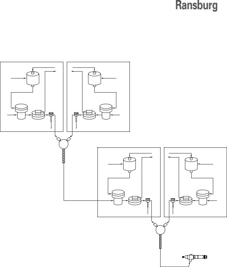
CHANNEL 3 |
CHANNEL 4 |
||
|
|
Y BLOCK |
||||
|
|
|
|
ANALOG CONTROL SIGNAL |
ANALOG CONTROL SIGNAL |
|
|
|
MIX TUBE |
E/P TRANSDUCER |
FLOW METER FEEDBACK |
FLOW METER FEEDBACK |
E/P TRANSDUCER |
|
|
|
AIR SUPPLY |
|
|
AIR SUPPLY |
|
|
|
PILOT SIGNAL |
|
|
PILOT SIGNAL |
|
|
|
FLUID |
|
|
FLUID |
|
|
|
REGULATOR |
|
|
REGULATOR |
|
|
|
|
FLOW |
FLOW |
|
|
|
|
|
METER |
METER |
|
|
|
|
|
VALVE |
VALVE |
|
|
|
|
FLUID SUPPLY |
|
|
FLUID SUPPLY |
|
|
|
|
CALIBRATION |
CALIBRATION |
|
|
|
|
|
CHECK VALVE |
CHECK VALVE |
|
|
|
|
|
|
Y BLOCK |
|
MIX TUBE
APPLICATOR
Figure 3b: Block Diagram for a Three-Component Gun
18 |
LN-9400-00.9 |

INPUT POWER
Input supply voltage connections should be made from a FUSED DISCONNECT that is located in an accessible area near the Control Enclosure.
Electrical conduit is recommended for the input power wiring. Use 3 cond. 14 ga. wire for incoming AC power supply.
If using SO type portable cord, a strain relief rated for the diameter of cord being used is required for protection against cord abrasion and damage.
The protective ground conductor must be terminated directly to the protective conductor ground terminallocatedinsidetheControlEnclosurewhich is marked with symbol - 
If there are large AC line voltage fluctuations or voltage transients such as those typically produced by heavy electric machinery or welding equipment, then a constant voltage transformer (CVT) or an uninterruptedly power supply (UPS) should be used between the FUSED DISCONNECT and the Control Panel.
!C A U T I O N
If a CVT or UPS is to be used on the input to the Control Panel, use a CVT with a Volt-Amp (VA) output rating equal to
or greater than the output voltage multiplied by the control panel fuse rating (see specification section). Also make sure that the device input ratings correspond with the voltage and frequency of the source supplied by the FUSED DISCONNECT. The device output should be rated for 240
VAC maximum.
DynaFlowTM User Manual - Installation
!C A U T I O N
Before applying power to the control panel, verify that it is set to match the source voltage. There may sometimes be a voltage selection switch (usually located on the DC power supplies) to select between 120 VAC and 240 VAC or different indicator bulbs may be required.
!W A R N I N G
Do not install or service this equipment or perform installation or adjustment procedures unless you are properly trained and qualified.
Installing and servicing this equipment requires access to parts which could cause electric shock or serious injury if work is not performed properly.
All work must comply with applicable local and national regulations and codes.
LN-9400-00.9 |
19 |

DynaFlowTM User Manual - Installation
INTERFACING TO THE
FLOW CONTROLLER
System I/O
SYSTEM INPUTS
|
|
|
Input |
Description |
|
Signals |
||
|
||
JOB Select |
These inputs are used to select a JOB number from the external PLC or other host controller. |
|
Inputs |
These inputs represent Binary Coded Decimal (BCD) that translates to 3 digits, each digit |
|
|
represented as a 4-bit binary code. The JOB Select inputs are used in conjunction with the |
|
|
GUN Mask inputs to determine which GUNs will accept the JOB number represented by the |
|
|
total of the active JOB Select Bits. See "Operation" section of this manual for details. These |
|
|
signals must be asserted prior to the JOB Strobe Input and held on slightly after the strobe |
|
|
signal goes low. |
|
|
|
|
JOB Strobe |
JOB Strobe requires a pulsed signal of at least 0.25 seconds duration. This signal is used in |
|
Input |
conjunction with the GUN MASK inputs and program select inputs to activate a new JOB # for |
|
|
any or all GUNs. When the controller detects this input, the program select inputs and GUN |
|
|
MASK inputs are read and action taken to load the new JOB # in the JOB # QUEUE. The new |
|
|
program select and GUN MASK inputs must be present before the PROGRAM SET STROBE |
|
|
is activated. Reference "Job Selection Timing Diagram Sample" in the "Operation" section. |
|
|
|
|
System Ready/ |
System Ready/Halt is a maintained signal that permits activation of any or all GUNs. For the |
|
Halt Input |
controller to operate, this signal must be maintained in the high state (24 VDC). When this |
|
|
signal is active, the system Ready/Halt output will be held ON. |
|
|
If the signal is lost, ALL GUNs will stop and the READY output is turned OFF. The GUNs must |
|
|
be restarted in the normal manner when this signal is again activated. The JOB # QUEUE for |
|
|
any GUN is not effected by the state of this input. |
|
|
|
|
Global GUN |
The Global GUN Enable is a maintained signal that overrides all of the individual External |
|
Enable |
Fault/Enable GUN inputs. Reference "GUN INPUTS". This is most useful when using RIO, |
|
|
RS-485, or RS-232C control and the discrete GUN I/O is not used through J3, J4, J5, or J6 |
|
|
of the mother board. |
|
|
|
SYSTEM OUTPUTS
Output |
Description |
|
Signals |
||
|
||
System Pulse |
The System Pulse output can be used as a watchdog function by a PLC or other external |
|
Output |
controller to determine if the flow controller is operating normally. The output is a 50% duty |
|
|
cycle, 0.5 HZ signal (2 pulses per second). |
|
|
|
|
System Fault |
A high signal on this output indicates that a system, GUN or other fault has occurred. The |
|
|
type of fault that causes this output to activate is selectable by the Horn Code located in the |
|
|
System Configuration table. |
|
|
|
|
System Spare |
Not used presently. |
|
|
|
20 |
LN-9400-00.9 |

DynaFlowTM User Manual - Installation
Gun I/O
Discrete GUN I/O provides the input control and output status signals required to interface each GUN with a PLC or similar controller, or other system control components. All GUN I/O can also be controlled or monitored through an external host controller operating through a serial data communications link or the state of each forced active through the local OPERATOR INTERFACE/host controller.
GUN INPUTS
Input |
Description |
Signals |
|
Trigger |
For automatic applicators: Starts fluid flow when supplied a 24 VDC signal assuming that the |
|
GUN has been put in run mode, is configured properly, and all other conditions are satisfied. |
|
For manual GUNs: A Trigger signal is required for the LOAD mode. The Trigger signal can |
|
be generated from an atomizing air flow switch. If a Trigger signal is received from the flow |
|
switch but no fluid flow is recorded from the catalyst (slaved) CHANNEL, then a FLOW TOO |
|
LOW fault is generated. This ensures that both material components are present to the GUN. |
|
If the dip switch, Pos #1 on the Channel Card is on, then this input is not used. Fluid flow |
|
through the master channel is used to indicate a TRIGGER ON condition. |
|
|
Halt/Reset |
Halt requires a pulsed signal of at least 0.25 seconds duration. It is used to stop the JOB # |
|
currently being executed or to stop a CLEAN/PURGE operation. GUN faults are also reset. |
|
While in HALT mode, any new JOB # selection using the JOB # Strobe will be entered into |
|
the Queue. The GUN will run the JOB # located in the Queue when a RUN signal is again |
|
supplied. The faults can still be viewed in the ERROR LOG data table. Halt has no effect on |
|
the JOB # in the Queue (Next JOB # to be run). |
|
|
Clean |
Clean requires a pulsed signal of at least 0.25 seconds duration. It forces the material regula- |
|
tors controlled by the GUN parameters to the full open position. This permits the fluid system |
|
to be cleaned. The removal of the GUN Enable signal or a HALT input signal is required to |
|
end the CLEAN operation. Actual cleaning sequencing (PURGE) such as soft air push-out is |
|
performed by the PLC, or other external controller. For details, refer to "Clean Mode" in the |
|
"Operation" section of this manual. |
|
|
Run |
This input will activate the GUN and will allow material flow if all other requirements are met. |
|
This is identical to pushing the GUN ON switch on the OPERATOR INTERFACE PANELS. |
|
Run requires a pulsed signal of at least 0.25 seconds duration. If this signal is reapplied once |
|
the JOB # has been started, then it is ignored. When this signal is supplied following a HALT, |
|
the JOB # stored in the queue will be activated. If no new JOB # was entered during the |
|
previous HALT, then the JOB # located in the queue will not change and will be used again. |
|
|
Gun Mask |
The Gun Mask input specifies whether a JOB # or toggled into GUN #n queue. This signal |
|
is used in conjunction with the system PROGRAM SELECTand PROGRAM STROBE inputs. |
|
A 24 VDC signal selects the GUN, a 0 VDC signal masks the GUN as ‘not used for the JOB |
|
# selected’. Multiple gun masks can be asserted simultaneously if it is desired to load more |
|
than one gun with the same JOB #. |
|
|
Total Reset |
Total Reset requires a pulsed signal of at least 0.25 seconds duration. This signal will reset |
|
the daily and JOB totals for the GUN. The non-resettable total will not be effected. |
|
|
LN-9400-00.9 |
21 |

DynaFlowTM User Manual - Installation
GUN INPUTS (Continued)
Input |
Description |
|
Signals |
||
|
||
Total Hold |
This signal will stop all totals for the CHANNEL as long as the signal is supplied, even if the |
|
|
GUN is running and there is fluid flow. The non-resettable total will not be effected. This is |
|
|
most often used during flush or soft air push cycles. It can also be used to account for only |
|
|
that material which is delivered onto parts. |
|
|
|
|
Transparent/ |
For GUNs configured as single-component, automatic mode only. This input is only acknowl- |
|
PID |
edged for run and load modes. This input must be supplied before the clean input or the trig- |
|
|
ger input if in run mode. This signal will place the CHANNEL in single-component, open loop |
|
|
mode and redirect the Analog Set Point Input directly to the E/P transducer control output. |
|
|
MAXIMUM FLOW RATE, MINIMUM FLOW RATE, MVR HIGH and MVR LOW parameters |
|
|
have no effect while in the transparent mode. The Out of Tolerance, FLOW TOO LOW and |
|
|
FLOW TOO HIGH faults will also be disabled while in the Transparent condition. |
|
|
|
|
Analog Hold |
This signal applies only to GUNs configured for single-component automatic mode. This |
|
|
signal will suspend PID control and freeze the analog control output to the E/P transducer to |
|
|
the current value. Normal PID operation will resume when this signal is removed. This would |
|
|
typically be used during flushing operations or for control stability in situations where there |
|
|
are extremely quick trigger cycles or equipment limitations. The Out of Tolerance, Flow Too |
|
|
Low and Flow Too High faults will also be disabled while in the Analog Hold condition. |
|
|
|
|
Load |
Load requires a pulsed signal of at least 0.25 seconds duration. The LOAD input places a |
|
|
manual, two-component GUN into LOAD MODE. LOAD MODE is a special way to meter |
|
|
both resin and catalyst to the applicator after the system has been through a CLEAN opera- |
|
|
tion while assuring accurate ratios. A GUN can be placed into the LOAD MODE directly from |
|
|
the RUN MODE. For details, refer to LOAD MODE in the "Operation" section of this manual. |
|
|
|
|
External Fault/ |
External Fault will detect a low signal of at least 0.25 seconds duration. This signal must be |
|
Enable |
maintained high for normal operation. No fluid flow will occur regardless of the operat- |
|
|
ing mode if the Enable input is not active. This input is supplied as an interlock for other |
|
|
equipment to automatically shut down the fluid flow controller. The system must be reset after |
|
|
the External Fault is returned to the high state. Reference "Recovering From Faults" in the |
|
|
"Operation" section of this manual. A Global Gun Enable system input will override this input. |
|
|
|
|
Spare Digital |
Not used presently. |
|
Input |
|
|
|
|
|
Analog Set |
This is a 0-10 VDC or 4-20 ma input signal (hardware selectable on the Channel Card) which |
|
Point |
can be used to command flow rate when the applicator is in AUTOMATIC mode. The scaling |
|
|
for input signal vs. flow rate is determined by the GUN JOB # parameters, MAXIMUM FLOW |
|
|
RATE and MINIMUM FLOW RATE. An Analog Set Point signal less than 0.25 VDC will cause |
|
|
the controller to use the SET POINT parameter located in the JOB table instead. |
|
|
|
|
Spare Analog |
Not used presently. |
|
Input |
|
|
|
|
22 |
LN-9400-00.9 |

DynaFlowTM User Manual - Installation
GUN OUTPUTS
Output |
Description |
|
Signal |
||
|
||
Ready |
This output is 24 VDC when the GUN is configured properly, a valid JOB is loaded. |
|
Active |
This output is 24 VDC when the GUN is RUN mode and flowing fluid or prepared to flow fluid. |
|
|
|
|
Fault |
This output is 24 VDC if a GUN fault condition occurs. |
|
Pot Life Timer |
This output is 24 VDC if the Pot-Life Timer has expired. This may also initiate a horn if set to |
|
|
do so in the Horn Code Configuration, set in the System Configuration. |
|
Clean/Load/ |
This output is 24 VDC when the GUN is placed in Clean, Load, or Calibrate Mode. |
|
Calibrate |
|
|
|
|
|
MVR Enable |
This output is 24 VDC anytime material should be flowing for the GUN. It is used to control |
|
|
trigger valve(s) installed at the inlet of the MVR valve(s) on fast-trigger JOBs. |
|
|
|
|
Analog Control |
This is a 0-10 VDC or 4-20 ma output signal (selectable on the Channel Module) which is |
|
Output |
connected to the transducer for control of the material regulator for the CHANNEL. The |
|
|
output signal is limited through the use of the JOB parameters, MVR HIGH and MVR LOW. |
|
|
Scaling is assumed to be 0 VDC (4 ma) equals 0 PSIG at the output of the E/P transducer |
|
|
and 10 VDC (20 ma) equals 100 PSIG at the output of the transducer. The MVR HIGH and |
|
|
MVR LOW JOB parameters are based on a percentage of the span of 0 to 100 PSIG. This |
|
|
an MVR LOW value of 10% equals 10 PSIG. |
|
|
|
|
Analog Flow |
This is a 0-10 VDC or 4-20 ma output signal (selectable on the Channel Module) indicating |
|
Rate Output |
the actual flow rate for the CHANNEL. Scaling of the output signal is accomplished through |
|
|
the use of the JOB parameters MAXIMUM FLOW RATE and MINIMUM FLOW RATE, where |
|
|
0 VDC (4 ma) equals the MINIMUM FLOW RATE value and 10 VDC (20 ma) equals the |
|
|
MAXIMUM FLOW RATE value. |
|
|
For the Master Channel, if DIP switch 2/2 on the Interface Module is off, the total flow rate for |
|
|
the gun is output and if the switch is on only the flow rate for the Master Channel is output. |
|
|
For the Slave Channel, only the flow rate for the Slave Channel is output. |
|
|
|
|
Fluid Line |
On guns configured for dual component operation, the pot-life expired output on the slave |
|
Flushed Output |
(B) channel indicates when the fluid line has been completely flushed. Once mixed material |
|
|
has entered the fluid line, this output is energized and it remains energized until the unit is |
|
|
completely flushed. That is, in order to turn this bit off, the amount of material programmed |
|
|
in for mixed volume must be expended from the applicator while the gun is in clean mode. |
|
|
|
|
User Interface |
Displays the current version of the user-interface software running on the user-interface PC. |
|
Revision |
|
|
|
|
|
Language |
This allows users to select between English and one Alternate Language. The alternate |
|
|
language text is stored on the flash drive or hard drive of the PC in files named: TEXT- |
|
|
MESS_ALT.TXT, PARAMHLP_ALT.TXT, LABELS_ALT.TXT, SOLENOIDVALVES_ALT.TXT, |
|
|
and HELP_ALT.TXT. |
|
|
|
LN-9400-00.9 |
23 |

DynaFlowTM User Manual - Installation
Control Rack Wiring
(Reference page 82 for terminal identification.)
Figure 4: Mother Board Terminals
24 |
LN-9400-00.9 |

Hardware Configuration
Reference "Addendum A" in the "Appendix" section for board level hardware settings. For new system installations, all hardware settings should already be in the correct positions. However, if replacing any electronic board assembly, verify that the settings of the new board are identical to those of the board being replaced. In the event that the replacement board is a newer revision and does not appear identical, refer to any documentation that was supplied with the board, or contact your Ransburg representative or contact Ransburg service.
Transducers
The transducers convert electrical control signals from the fluid flow controller to the air pressure signals used to operate the material regulators. The transducers can be either current controlled (4-20 ma) or voltage controlled (0-10 VDC). The transducers can be mounted separately or collectively depending on the installation requirements.
Make sure that the Channel Module jumper settings match the type of transducer being used (refer to "Channel Module Mother Board Jumper Settings Channel 1 I/O and Channel 2 I/O" in the
"Appendix" section).
The electrical-to-pneumatic (E/P) transducers are supplied as separate sub-assemblies or as part of a standard transducer panel. The transducer panel offers a convenient way to mount transducers for 2K applications. There are typically two transducers located in each panel with electrical terminals and an air supply input.
The transducers may also be mounted individually on any air drop outside of the Class 1, Division 1 hazardous location if:
1.Tubing and cable lengths do not violate the minimum and maximum lengths specified in the
"Installation" section of this manual under Equipment Locations".
2.The air supply meets the specifications as listed in the "Introduction" section of this manual under "Pneumatic Specifications" or those published with the transducer.
A 1:1 volume booster may also be connected
DynaFlowTM User Manual - Installation
directly to the transducer output when; operating a DR-1TM Fluid Regulator, if pilot line lengths are longer than recommended, or of a larger tubing diameter is used other than that recommended.
Keep the distance between the transducer to the material regulator as short as possible, without violating the minimum lengths specified, to avoid system response delays and to achieve the optimum fluid flow characteristics for the system.
Material Regulators and Flow Meters
The location and mounting of the material regulators and flow meters is specific to each installation. The information presented here is intended as a guideline only. Reference should be made to the supplied documentation specific to your installation.
Fluid Supply Requirements
•The fluid supply must be free of pulsation and surges.
•A fluid strainer/filter must be installed immediately before the material regulators. The elment size of the strainer should be 100 mesh or per the recommendation of your Ransburg representative.
•For Two-Component (2K) Systems: Selector valves are required for calibration or verifying of the flow meters and should be mounted close to the mixing block. These are supplied as part of the standard fluid panel. Drawings created specifically for your system will provide detailed information about valve type and location. Mount the calibration valves in an easily accessible area close to the mixing block. For most applications the flow meter and material regulator are mounted as an assembly as close as possible to the mixing block and calibration valves.
•For systems with fast trigger cycles that utilize weepless MVR valves, or where dynamic control of fluid flow rates (different flow rate during a JOB), consider installing trigger valves (typically color control valves) immediately upstream of the MVR valves so that the CHANNELs may be placed in
LN-9400-00.9 |
25 |

DynaFlowTM User Manual - Installation
Analog Hold mode without causing the fluid tubes to pressurize to the material supply pressure while the GUN is not triggered.
•For systems with fast trigger cycles or where dynamic control of fluid flow rates (different flow rates during a JOB), mount the E/P transducer as close to the material regulator as possible. Remember that the transducers MUST be mounted outside of the hazardous location (refer to NFPA-70, NEC). For applications where the requested fluid flow is for the most part consistent, and transitional response time of the system is not as critical, then the E/P transducers may be located in the main control panel.
•Be sure that stainless steel tubing or piping and stainless steel fittings are used for all fluid lines and connections where metal is desired.
•Always mount the flow meter and regulator as close as feasible to the applicator. This reduces paint line pulsation due to applicator reciprocators and reduces the possibility of a paint leak effecting paint delivered to the part.
NOTES
26 |
LN-9400-00.9 |
Loading...