


SERVICE MANUAL
AA-08-01.1
January - 2013
EVOLVER 303TM DUAL PURGE SOLVENTBORNE
ROBOTIC ATOMIZERS
MODEL: A12374-XXX
With
Technology
IMPORTANT: Before using this equipment, carefully read SAFETY PRECAUTIONS, starting on page 1, and all instructions in this manual. Keep this Service Manual for future reference.
Service Manual Price: $50.00 (U.S.)


Evolver 303 Dual Purge Robotic Atomizers - Contents
CONTENTS |
|
|
PAGE |
SAFETY: |
1-4 |
SAFETY PRECAUTIONS............................................................................................................. |
1 |
HAZARDS / SAFEGUARDS......................................................................................................... |
2-4 |
INTRODUCTION: |
5-12 |
RANSBURG ELECTROSTATIC PROCESS...................................................................... |
5 |
EVOLVER 303 DUAL PURGE SOLVENTBORNE |
|
SPRAY APPLICATORS.............................................................................................................. |
5-6 |
SPECIFICATIONS....................................................................................................................... |
7 |
EVOLVER 303 DUAL PURGE APPLICATOR ASSEMBLY..................................................... |
8 |
EVOLVER 303 DUAL PURGE TUBING BUNDLE ASSEMBLY (METRIC).............................. |
8 |
EVOLVER 303 DUAL PURGE SOLVENTBORNE |
|
ROBOTIC APPLICATORS.......................................................................................................... |
9 |
FEATURES.................................................................................................................................. |
10 |
A12374-XXX EVOLVER DUAL PURGE SPRAY |
|
APPLICATOR ASSEMBLY.......................................................................................................... |
11 |
TOOL CENTER-POINT COMPARISONS TABLE..................................................................... |
12 |
INSTALLATION: |
13-24 |
EVOLVER 303 DUAL PURGE ROBOTIC ATOMIZER |
|
INSTALLATION............................................................................................................................ |
13 |
POWER SUPPLY ASSEMBLY................................................................................................... |
13 |
MOUNTING.................................................................................................................................. |
13 |
ELECTRICAL AND FIBER OPTIC CONNECTIONS................................................................. |
13 |
FLUID CONNECTIONS............................................................................................................... |
13 |
TYPICAL INSTALLATION........................................................................................................... |
13 |
LOW VOLTAGE CABLE CONNECTIONS................................................................................. |
14 |
EVOLVER 303 DUAL PURGE SPRAY APPLICATOR |
|
AIR AND FLUID LAYOUT........................................................................................................... |
15 |
APPLICATOR AND MANIFOLD ASSEMBLY............................................................................ |
16-17 |
LOW VOLTAGE CABLE INSTALLATIONS................................................................................ |
17-18 |
LOW VOLTAGE CABLE ON ROBOT......................................................................................... |
19 |
BULKHEAD CUT-OUT DIAGRAM.............................................................................................. |
20 |
ROBOT PLATE............................................................................................................................ |
20 |
QUICK-DISCONNECT CABLES................................................................................................ |
20 |
SIGNAL IDENTIFICATION TABLE BELLS (APPLICATORS)................................................... |
21 |
APPLICATOR AND MANIFOLD ASSEMBLY / PARTS LIST.................................................... |
22 |
SPRAY / BELL APPLICATOR TRIGGERING............................................................................ |
23 |
CONVERSION SCHEMATIC..................................................................................................... |
23 |
TUBING BUNDLE INSTALLATION............................................................................................ |
24 |
BUNDLE LUBRICATION............................................................................................................. |
24 |
(Continued On Next Page)

Evolver 303 Dual Purge Robotic AtomizersContents
CONTENTS (Cont.) |
|
|
PAGE |
OPERATION: |
25-28 |
SPRAY APPLICATOR CONTROLS........................................................................................... |
25 |
HVLP SPRAY............................................................................................................................... |
25-26 |
FLUID VALVE CONTROLS......................................................................................................... |
26 |
DUAL PURGE SPRAYING......................................................................................................... |
26-27 |
DUAL PURGE AIR AND FLUID PASSAGE SCHEMATIC........................................................ |
28 |
MAINTENANCE: |
29-52 |
ROUTINE MAINTENANCE SCHEDULE.................................................................................... |
29-30 |
PROCEDURES............................................................................................................................ |
30-32 |
SPRAY HEAD REMOVAL / ASSEMBLY / PARTS LIST............................................................ |
33-34 |
SERVICE...................................................................................................................................... |
35 |
SPRAY HEAD ASSEMBLY.......................................................................................................... |
35-38 |
79138 EVOLVER 303 DUAL PURGE APPLICATOR HEAD |
|
ASSEMBLY / PARTS LIST........................................................................................................... |
39-40 |
REMOVING SPRAY APPLICATOR FROM THE |
|
REAR MANIFOLD ASSEMBLY................................................................................................... |
41 |
EVOLVER 303 DUAL PURGE 60° SINGLE HEAD |
|
APPLICATOR ASSEMBLY / PARTS LIST.................................................................................. |
42 |
DISASSEMBLY OF A12373 SPRAY APPLICATOR |
|
ASSEMBLY / PARTS LIST........................................................................................................... |
43-44 |
CASCADE WIRE PLUG ASSEMBLY.......................................................................................... |
45 |
LOW VOLTAGE CABLE REMOVAL / PARTS LIST................................................................... |
45-47 |
A12376-00 DUAL PURGE VALVE MANIFOLD |
|
DISASSEMBLY / PARTS LIST..................................................................................................... |
48 |
TROUBLESHOOTING GUIDE.................................................................................................... |
49-52 |
PARTS IDENTIFICATION: |
53-78 |
A12374 SPRAY APPLICATOR ASSEMBLY W/A12283 |
|
TUBING BUNDLE ASSEMBLY/ PARTS LIST............................................................................ |
53-54 |
79138-01/-04 CONVENTIONAL AND 79138-02/-05 HVLP |
|
SPRAY HEAD ASSEMBLY / PARTS LIST.................................................................................. |
55-57 |
79179-00 SINGLE HEAD 60° / PARTS LIST............................................................................... |
58 |
79243-00 DUAL HEAD 60° / PARTS LIST................................................................................... |
58 |
79180-00 SINGLE HEAD 90° / PARTS LIST............................................................................... |
59 |
79224-00 DUAL HEAD 90° / PARTS LIST................................................................................... |
59-60 |
A12373 MANIFOLD ASSEMBLY / PARTS LIST......................................................................... |
61-62 |
A12375-01 REAR PLATE ASSEMBLY (SINGLE PURGE) / |
|
PARTS LIST.................................................................................................................................. |
63-64 |
A12283-XXXXXXX TUBING BUNDLE ASSEMBLY (METRIC) / |
|
PARTS LIST.................................................................................................................................. |
65-66 |
SIGNAL IDENTIFICATION TABLE BELLS (APPLICATORS).................................................... |
67 |
(Continued On Next Page)

Evolver 303 Dual Purge Robotic Atomizers - Contents
CONTENTS (Cont.) |
|
|
PAGE |
PARTS IDENTIFICATION (Cont.): |
53-78 |
A12283-XXXXXXX TUBING BUNDLE ASSEMBLY MODEL |
|
IDENTIFICATION (METRIC)....................................................................................................... |
68-69 |
A10406 OR LECU5004 MICROPAK CONTROL UNIT............................................................... |
70 |
ACCESSORIES AND SERVICE KITS........................................................................................ |
70-73 |
REPAIR KITS................................................................................................................................ |
74 |
SERVICE PARTS......................................................................................................................... |
75 |
LUBRICANTS AND SEALERS.................................................................................................... |
75 |
EVOLVER 303 DUAL PURGE RECOMMENDED SPARE PARTS.......................................... |
76-77 |
WARRANTY POLICIES: |
79 |
LIMITED WARRANTY.................................................................................................................. |
79 |
Evolver 303 Dual Purge Robotic Atomizers - Safety
SAFETY
SAFETY PRECAUTIONS
Before operating, maintaining or servicing any Ransburg electrostatic coating system, read and understand all of the technical and safety literature for your Ransburgproducts. Thismanual containsinformation thatisimportantforyoutoknowandunderstand. This informationrelatestoUSERSAFETYandPREVENTING EQUIPMENT PROBLEMS. To help you recognize this information, we use the following symbols. Please pay particular attention to these sections.
A WARNING! states information to alert you to a situation that might cause serious injury if instructions are not followed.
A CAUTION! states information that tells how to prevent damage to equipment or how to avoid a situation that might cause minor injury.
A NOTE is information relevant to the procedure in progress.
While this manual lists standard specifications and service procedures, some minor deviations may be found between this literature and your equipment. Differences in local codes and plant requirements, material delivery requirements, etc., make such variations inevitable. Compare this manual with your system installation drawings and appropriate Ransburg equipment manuals to reconcile such differences.
Careful study and continued use of this manual will provideabetterunderstandingoftheequipmentand process, resulting in more efficient operation, longer trouble-freeserviceandfaster,easiertroubleshooting. If you do not have the manuals and safety literature foryourRansburgsystem,contactyourlocalRansburg representative or Ransburg.
!W A R N I N G
>The user MUST read and be familiar with the Safety Section in this manual and the Ransburg safety literature therein identified.
>This manual MUST be read and thoroughly understoodbyALLpersonnelwhooperate,clean or maintain this equipment! Special care should betakentoensurethattheWARNINGSandsafety requirements for operating and servicing the equipment are followed. The user should be aware of and adhere to ALL local building and fire codes and ordinances as well as NFPA-33 SAFETY STANDARD or applicable country safety standards prior to installing, operating, and/or servicing this equipment.
!W A R N I N G
>The hazards shown on the following page may occur during the normal use of this equipment. Please read the hazard chart beginning on page 2.
1 |
AA-08-01.1 |

Evolver 303 Dual Purge Robotic Atomizers - Safety
AREA |
HAZARD |
SAFEGUARDS |
Tells where hazards |
Tells what the hazard is. |
Tells how to avoid the hazard. |
may occur. |
|
|
Spray Area |
Fire Hazard |
Fireextinguishingequipmentmustbepresentinthespray |
|
|
area and tested periodically. |
|
Improper or inadequate oper- |
Spray areas must be kept clean to prevent the accumula- |
|
ationandmaintenanceproced- |
|
|
tion of combustible residues. |
|
|
ures will cause a fire hazard. |
|
|
|
|
|
Protection against inadvertent |
Smoking must never be allowed in the spray area. |
|
The high voltage supplied to the atomizer must be turned |
|
|
arcingthatiscapableofcausing |
|
|
fire or explosion is lost if any |
off prior to cleaning, flushing or maintenance. |
|
|
|
|
safety interlocks are disabled |
When using solvents for cleaning: |
|
during operation. Frequent |
|
|
|
|
|
power supply shut-down indi- |
Thoseusedforequipmentflushingshouldhaveflashpoints |
|
cates a problem in the system |
equal to or higher than those of the coating material. |
|
requiring correc-tion. |
Those used for general cleaning must have flash points |
|
|
|
|
|
above 100°F (37.8°C). |
|
|
Spray booth ventilation must be kept at the rates required |
|
|
by local and/or country codes. In addition, ventilation |
|
|
must be maintained during cleaning operations using |
|
|
flammable or combustible solvents. |
|
|
Electrostatic arcing must be prevented. |
|
|
Test only in areas free of combustible material. |
|
|
Testing may require high voltage to be on, but only as |
|
|
instructed. |
|
|
Non-factoryreplacementpartsorunauthorizedequipment |
|
|
modifications may cause fire or injury. |
|
|
If used, the key switch bypass is intended for use only |
|
|
during set-up operations. Production should never be |
|
|
done with safety interlocks disabled. |
|
|
The paint process and equipment should be set up and |
|
|
operated in accordance with local and/or country safety |
|
|
codes. |
|
|
|
General Use and |
Improper operation or mainte- |
Personnel must be given training in accordance with the |
Maintenance |
nance may create a hazard. |
requirements of NFPA-33. |
|
Personnel must be properly |
Instructions and safety precautions must be read and |
|
trained in the use of this equip- |
understood prior to using this equipment. |
1 |
ment. |
Comply with appropriate local, state, and national codes |
|
|
|
|
|
governing ventilation, fire protection, operation mainte- |
|
|
nance,andhousekeeping.ReferenceOSHA,NFPA-33,and |
|
|
your insurance company requirements. |
|
|
|
AA-08-01.1 |
2 |
Evolver 303 Dual Purge Robotic Atomizers - Safety
AREA |
HAZARD |
SAFEGUARDS |
Tells where hazards |
Tells what the hazard is. |
Tells how to avoid the hazard. |
may occur. |
|
|
Toxic Substances |
Certain material may be harmful if |
Follow the requirements of the Material Safety Data |
|
inhaled, or if there is contact with |
Sheet supplied by coating material manufacturer. |
|
the skin. |
Adequate exhaust must be provided to keep the air |
|
|
|
|
|
free of accumulations of toxic materials. |
|
|
Use a mask or respirator whenever there is a chance of |
|
|
inhaling sprayed materials. The mask must be compat- |
|
|
ible with the material being sprayed and its concentra- |
|
|
tion. Equipment must be as prescribed by an industrial |
|
|
hygienist or safety expert, and be NIOSH approved. |
|
|
|
Explosion Hazard/ |
Halogenatedhydrocarbonsolvents |
Aluminum is widely used in other spray application |
Incompatible |
for example: methylene chloride |
equipment - such as material pumps, regulators, trig- |
Materials |
and 1,1,1,-Trichloroethane are not |
gering valves, etc. Halogenated hydrocarbon solvents |
|
chemically compatible with the |
must never be used with aluminum equipment during |
|
aluminum that might be used in |
spraying, flushing, or cleaning. Read the label or data |
|
many system components. The |
sheet for the material you intend to spray. If in doubt as |
|
chemical reaction caused by these |
to whether or not a coating or cleaning material is com- |
|
solvents reacting with aluminum |
patible, contact your material supplier. Any other type |
|
can become violent and lead to an |
of solvent may be used with aluminum equipment. |
|
equipment explosion. |
|
|
|
|
Electrical |
High voltage equipment is utilized. |
Thepowersupply,optionalremotecontrolcabinet,and |
Equipment |
Arcing in areas of flammable or |
all other electrical equipment must be located outside |
|
combustible materials may occur. |
Class I or II, Division 1 and 2 hazardous areas. Refer to |
|
Personnel are exposed to high |
applicable code for specific area and/or country. |
|
voltage during operation and |
|
|
maintenance. |
Turn the power supply OFF before working on the |
|
Protection against inadvertent arc- |
equipment. |
|
|
|
|
ingthatmaycauseafireorexplosion |
Test only in areas free of flammable or combustible |
|
is lost if safety circuits are disabled |
material. |
|
during operation. |
Testing may require high voltage to be on, but only as |
|
|
|
|
Frequent power supply shutdown |
instructed. |
|
indicates a problem in the system |
|
|
which requires correction. |
Production should never be done with the safety cir- |
|
An electrical arc can ignite coating |
cuits disabled. |
|
|
|
|
materials and cause a fire or explo- |
Beforeturningthehighvoltageon,makesurenoobjects |
|
sion. |
are within the sparking distance. |
|
|
|
3 |
AA-08-01.1 |

Evolver 303 Dual Purge Robotic Atomizers - Safety
AREA |
HAZARD |
SAFEGUARDS |
Tells where hazards |
Tells what the hazard is. |
Tells how to avoid the hazard. |
may occur. |
|
|
Robot Work Area- |
Improper use or maintenance can |
Applicatoradjustmentsormaintenanceshouldbedone |
General Use and |
lead to hazardous conditions, par- |
after the robot is taken out of service. Do not adjust or |
Maintenance |
ticularly from unexpected robot |
repair the applicator if the robot is operating or stand- |
|
manipulator movement. |
ing ready to start. |
|
|
Refertorobotoperatinginstructionsfortheprocedures |
|
|
to take the robot out of service. |
|
|
|
Personnel Safety |
Skin puncturing by sharp elec- |
Take precautions to see that flesh is not punctured by |
|
trode. |
sharp electrode. |
|
|
|
AA-08-01.1 |
4 |

Evolver 303 Dual Purge Robotic Atomizers - Introduction
INTRODUCTION
THE RANSBURG ELECTROSTATIC PROCESS
Thisprocessisamethodforelectrostaticallyapplying coatings to objects. A power supply produces a high voltage charge which is supplied to the applicator, creatinganelectrostaticfieldbetweentheapplicator and the target object. The target is electrostatically grounded through its support which may be either stationary or moving.
A regulated fluid system delivers coating material to the applicator, where it is atomized forming a spray mist. There, under the influence of the electrostatic field, the atomized coating becomes electrostatically charged. The charged particles are attracted to and deposited on the grounded target object. The forces between the charged particles and the target are sufficient to turn overspray around and deposit it on the back surface of the target. Therefore, a higher percentage of the spray is deposited.
EVOLVER™ 303 DUAL PURGE SOLVENTBORNE SPRAY APPLICATORS
TheEvolver™303DualPurgeSprayAppli-catorsSystem will allow for the use of spray applicators or bell applicators with minimal required down-time during the switching process. This system can also operate as a spray applicator system only that later can be upgradedtoallowforbellapplicatorshaving"Unilink Technology"to be used. This system can allow a user currently possessing an RMA-303 bell system to use spray applicators as well, with minimal conversion required. Lastly, this system is a true dual purge system in that paint can be sprayed with full voltage on, while simultaneously color changing the second paint line. The Evolver 303 Dual Purge Solventborne Applicator line consists of both 60° and 90° single and dual-headed 100kV automatic electrostatic applicators. Developed for use on robot, the Evolver 303 Dual Purge spray applicator incorporates a unique 1/3 turn quick-disconnect spray head and a one piece slide over manifold cover, providing the user an efficient tool for the electrostatic application of coatings.
There are two single-head models of the Evolver 303 Dual Purge Applicators (see Figure 1). Each model differsintheapplicatortoaxisorientationofthespray head. These models are:
A12374-0XX 60° Single-Head
A12374-1XX 90° Single-Head
Twodual-headversionsoftheEvolver303DualPurge Applicator are also available (see Figure 1). The dualheaded applicators are primarily used where high volume fluid delivery is required. The dual-headed applicator is available in two different configurations as follows:
A12374-2XX 60° Dual-Head
A12374-3XX 90° Dual-Head
5 |
AA-08-01.1 |
Evolver 303 Dual Purge Robotic Atomizers - Introduction
The Evolver 303 Dual Purge Spray Applicator System consists of four major components:
1.Quick-Disconnect Spray Head
2.Applicator Head Mounting Block Assembly
3.Valve Manifold Assembly (Includes the High Voltage Cascade with a Quick-Disconnect Ring)
4.Rear Tubing Manifold Assembly (both English and Metric)
The spray head(s) and valve manifold contain the fluid, air, and high voltage passages. All fluid passagescontainstainlesssteeland/ornylonfittings, compatiblewithhalogenatedhydrocarbonsolvents. The robot manifold incorporates stainless steel fluid connections.
The high voltage cascade is entirely encapsulated withasolventresistantepoxy. Thiscascadegenerates voltages up to 100kV fed by a low voltage cable.
There are three sources for the high voltage supply to the Evolver 303 Dual Purge Applicators:
•MicroPak™ Control Unit (LECU5004)
•Stand-alone control/power supply unit (A10406)
•MicroPakTM Control Unit (LECU5004-31)
The MicroPak Power Supply control unit provides a low voltage signal through the robot manifold to the spray applicator. The high voltage cascade located within the applicator converts the low voltage DC signal to a high voltage electrostatic output.
For applications that have the ability to control fan and atomization air remotely, the bleed style head is available.
NOTES
AA-08-01.1 |
6 |

Evolver 303 Dual Purge Robotic Atomizers - Introduction
Specifications
Environmental/Physical |
Electrical Requirements |
|||||
|
|
|
|
|
||
Robot/Mounting Compatibility: |
|
Output Voltage: |
30-100kV |
|||
|
All hollow wrist robots |
|
Output Range: |
0-85 µA |
||
Applicator Control Unit: |
|
|
||||
|
|
Paint Flow Rate: Variable to 1500 cc/min. |
||||
MicroPak Control Unit - LECU5004-31 |
|
|||||
Stand-Alone Control Unit - A10406 |
|
(Depending on viscosity and configuration) |
||||
Operating Temperature |
|
|
Trigger Response |
|
|
|
Range: |
55°F (12.8°C) - 131°F (55°C) |
|
Time: |
134ms Open |
||
Approximate Weight |
|
|
|
318ms Closed |
||
|
|
|
|
|
||
Single-Headed: |
|
|
Operating Air Pressures |
|
|
|
60° |
|
9.02 lb. (4.1 Kg) |
|
Atomizing Air: |
100 psig (6.9 bar) |
|
90° |
|
8.71 lb. (3.9 Kg) |
|
|
max. |
|
Dual-Headed: |
|
|
|
|
|
|
60° |
|
10.91 lb. (4.9 Kg) |
|
Fan Air: |
100 psig (6.9 bar) |
|
90° |
|
10.76 lb. (4.9 Kg) |
|
|
max. |
|
Manifold: |
|
|
|
|
|
|
A12373-XX |
6.82 lb. (3.1 Kg) |
|
Trigger Pilot: |
70 psig min./100 |
||
Length |
|
(No tubing or cable) |
|
|
psig |
|
|
|
|
|
(4.8 - 6.9 bar) max. |
||
Single-Headed: |
|
|
|
|
|
|
60° |
|
16.5-inch (41.9 cm) |
|
Dump Pilot: |
70 psig min./ |
|
90° |
|
13.6-inch (34.5 cm) |
|
|
100 psig max. |
|
Dual-Headed: |
|
|
|
(4.8 - 6.9 bar) |
||
60° |
|
15.8-inch (40.1 cm) |
|
|
|
|
90° |
|
12.4-inch (31.5 cm) |
|
Operating Fluid |
|
|
Tubing Manifolds (Metric): |
|
|
Pressure: |
200 psig |
||
|
|
|
(13.8 bar) max. |
|||
A12283-0XXXXXX |
Air Tubing not |
|
|
100 psig |
||
A12283-1XXXXXX |
included |
|
|
(6.9 bar) max. |
||
4 1/2m (15-ft.) |
|
|
Regulated (with |
|||
A12283-2XXXXXX |
9m (30-ft.) |
|
|
on-board regulator) |
||
|
|
|
|
|
|
|
|
|
|
|
|
|
|
|
|
|
|
robot Manifold Tubing |
|
Tubing Bundle |
|
|
|
|
Requirements |
|
Metric |
|
|
|
|
Atomizing Air |
|
8mm OD Nylon |
|
|
|
|
Fan Air |
|
8mm OD Nylon |
|
|
|
|
Trigger Air |
|
6mm OD Nylon |
|
|
|
|
Dump Pilot |
|
4mm OD Nylon |
|
|
|
|
Fluid: |
|
8mm OD |
|
|
|
|
|
|
(Non-Shielded) |
|
|
|
|
Dump: |
|
7mm ID |
|
|
|
|
|
|
|
7 |
AA-08-01.1 |
Evolver 303 Dual Purge Robotic Atomizers - Introduction
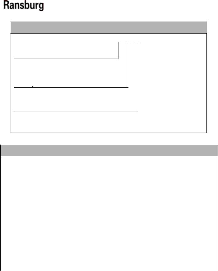
EVOLVER 303 DUAL PURGE APPLICATOR ASSEMBLY
A12374 - A B C
Head Configuration
0= 60° Single-Head
1= 90° Single-Head
2= 60° Dual-Head
3= 90° Dual-Head
Body Style
0 = For Highly Resistive Materials (Clear Coat)
1 = For Conductive Materials (Base / Clear)
2 = For Highly Conductive Materials (Base / Clear)
Atomization Technology
0 = Conventional Spray / Non-Bleed
1 = HVLP Spray / Non-Bleed
4 = Conventional Spray / Bleed
5 = HVLP Spray / Bleed
EVOLVER 303 DUAL PURGE TUBING BUNDLE ASSEMBLY (METRIC)
A12283 - A BB |
|
CC DD |
|
|
||||||||||
Tubing Bundle Length |
|
|
|
|
|
|
|
|
|
|
|
|
||
|
|
|
|
|
|
|
|
|
Robot Adapter |
|||||
0 = Air Tubing (Not Included) |
|
|
|
|
|
|
|
|
|
00 |
= Adapter Not Included |
|||
1 = 4.5m (15-ft.) Long Tubing Assembly |
|
|
|
01 |
= Adapter (Fanuc P-155) 78983-00 |
|||||||||
2 = 9m (30-ft.) Long Tubing Assembly |
|
|
|
02 |
= Adapter (ABB 5400, 5002) 79107-00 |
|||||||||
Low Voltage Cable Length |
|
|
|
03 |
= Adapter (Fanuc-P200/P-250) 79131-00 |
|||||||||
|
|
|
04 |
= Adapter (KAWASAKI-KE610L) A10847-00 |
||||||||||
0 0 = Low Voltage Cable Not Included |
|
|
|
05 |
= Adapter (MOTOMAN-PX2850) A10848-00 |
|||||||||
01 = 15-ft. Low Voltage - Quick Connect to MicroPak |
|
|
06 |
= Adapter (MOTOMAN-PX2900) A10849-00 |
||||||||||
02 = 25-ft. Low Voltage - Quick Connect to MicroPak |
|
|
07 |
= Adapter (B & M LZ2000) A10851-00 |
||||||||||
03 = 40-ft. Low Voltage - Quick Connect to MicroPak |
|
|
08 |
= Adapter (ABB 5400 Enhanced Wrist) A12036-00 |
||||||||||
04 = 50-ft. Low Voltage - Quick Connect to MicroPak |
|
|
|
|
|
|
|
|
|
|||||
05 = 75-ft. Low Voltage - Quick Connect to MicroPak |
|
|
|
|
|
Fiber Optic Cable Length |
||||||||
|
|
|
|
|
|
|
|
00 |
= Fiber Optic Cable Not Included |
|
||||
|
|
|
|
|
|
01 |
= 15-ft. Long Fiber Optic Cable |
|||||||
|
|
|
|
|
|
02 |
= 25-ft. Long Fiber Optic Cable |
|||||||
|
|
|
|
|
|
03 |
= 40-ft. Long Fiber Optic Cable |
|||||||
|
|
|
|
|
|
04 |
= 50-ft. Long Fiber Optic Cable |
|||||||
|
|
|
|
|
|
05 |
= 75-ft. Long Fiber Optic Cable |
|||||||
|
|
|
|
|
|
06 |
= 100-ft. Long Fiber Optic Cable |
|||||||
AA-08-01.1 |
8 |
Evolver 303 Dual Purge Robotic Atomizers - Introduction
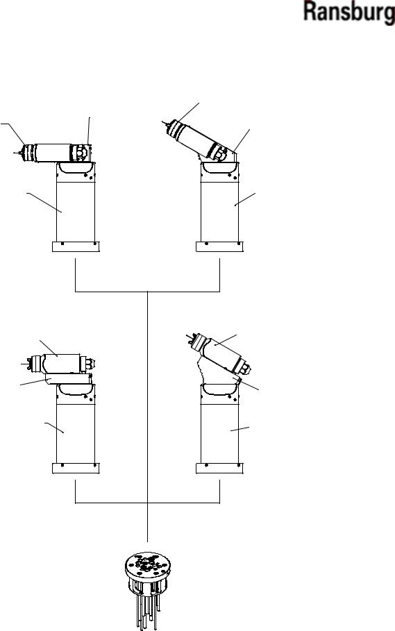
|
|
SPRAY HEAD |
|
|
|
ASSY. |
|
SPRAY HEAD |
MOUNTING |
|
|
BLOCK ASSY. |
|
||
ASSY. |
MOUNTING |
||
|
|||
|
|
BLOCK ASSY. |
VALVE MANIFOLD |
VALVE MANIFOLD |
ASSY. |
|
|
ASSY. |
A12374-3XX |
A12374-2XX |
90° DUAL HEAD |
60° DUAL HEAD |
SPRAY HEAD |
SPRAY HEAD |
|
ASSY. |
||
ASSY. |
||
|
MOUNTING |
MOUNTING |
|
BLOCK ASSY. |
||
BLOCK ASSY. |
||
|
||
VALVE MANIFOLD |
VALVE MANIFOLD |
|
ASSY. |
||
|
ASSY. |
|
A12374-1XX |
A12374-0XX |
|
90° SINGLE HEAD |
60° SINGLE HEAD |
A12283-XXXXXXX REAR MANIFOLD TUBING ASSY. - METRIC
Figure 1: Evolver 303 Dual Purge Solventborne Robotic Applicators
9 |
AA-08-01.1 |
Evolver 303 Dual Purge Robotic Atomizers - Introduction
FEATURES
The features of the Evolver 303 Dual Purge Series Applicators include:
!Quick-disconnect spray head
!High quality Ransburg air cap and fluid nozzle
!Various adapter plates available to match most robotic mounting configurations
!No external high voltage cable. The internally mounted high voltage cascade requires only low voltage control wiring
!Less waste to the spray booth with the dump valve located internally next to the feed tube
!Assembly components made of durable engineered resin material for optimum mechanical strength and solvent resistance
!Heavy duty design ensures excellent service life even when subjected to the quick motions of robotic applicators
!Small, light weight package allows for better maneuverability in tight areas
!Negligible maintenance down time with the quick-disconnect feature. An atomizer can be exchanged in less than two minutes for off-line maintenance
!Field proven high voltage system
!Dual start, dual pitch air cap retaining ring
!Quick color change capability
!Clean interior design with slip-on shroud
!Internal fan and atomization air control valve, with a mechanically timed trigger sequence
!Color coded air and trigger actuation lines
!Quick change to a RMA-303 bell applicator
!True dual purge technology, allowing the user to spray one color at voltage, while simultaneously purging the second color
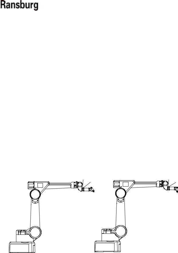
ROBOT SPACER PLATE |
ROBOT SPACER PLATE |
ROBOT MANIFOLD QUICK |
ROBOT MANIFOLD QUICK |
DISCONNECT RING |
DISCONNECT RING |
A12374-0XX |
A12374-1XX |
60° SINGLE HEAD |
90° SINGLE HEAD |
MOUNTED ON ROBOT |
MOUNTED ON ROBOT |
Figure 2: Typical Robotic Applicator Mounting
AA-08-01.1 |
10 |

Evolver 303 Dual Purge Robotic Atomizers - Introduction
A12374-XXX Evolver DUAL PURGE SPRAY APPLICATOR assembly
Thesprayapplicatorassemblyisdesignedtoconnect to hollow wrist robots. A low voltage control cable is supplied with the tubing bundle to connect the cascade to the MicroPak power supply.
Tool Center-Point
Figure 3 shows the tool center-point information for the four applicators. For dual head applicators, the tool center-point is based upon the convergence point. For the single head applicators it is based upon a 10" target distance. The "Tool Center-Point Comparisons Table" compares the tool center-point of several automatic spray applicators.
11 |
AA-08-01.1 |

Evolver 303 Dual Purge Robotic Atomizers - Introduction
ROBOT ADAPTER AND
MOUNTING PLATE
|
|
|
|
|
|
|
|
|
ROBOT ADAPTER AND |
||
|
|
|
|
|
|
|
|
|
MOUNTING PLATE |
||
|
|
|
|
63 |
[161.4] |
|
|
|
|
|
|
|
|
|
|
8 |
|
|
|
|
|
|
|
|
|
|
|
11 [279.1] |
|
|
|
|
|
|
|
|
|
|
|
|
|
|
1 |
|
|
|
|
|
|
|
|
|
|
|
152 |
[392.8] |
|
|
10 [254.0] |
123 |
|
|
|
|
|
|
|
|
|
|
TARGET DISTANCE |
[314.5] |
|
|
|
|
121 |
|
|
||||
8 |
|
|
|
|
|
|
|
|
[310.2] |
||
153 |
|
|
|
|
|
|
|
4 |
|
|
|
[390.6] |
|
|
|
|
1 |
|
|
||||
8 |
|
|
|
|
|
|
|
|
|
||
|
|
|
|
|
|
|
|
|
154 |
[386.3] |
|
|
|
|
|
CONVERGENCE POINT |
|
|
|
|
|
||
|
|
|
|
DUAL HEAD 90° |
|
|
|
|
SINGLE HEAD 90° |
||
ROBOT ADAPTER AND |
|
|
|
|
|
|
|
||||
MOUNTING PLATE |
|
|
|
|
|
|
|
|
|||
|
|
|
|
|
|
|
|
|
ROBOT ADAPTER AND |
||
|
|
|
|
|
|
|
|
|
MOUNTING PLATE |
|
|
|
|
|
|
|
6 [151.9] |
|
|
|
|
|
|
|
|
|
|
|
|
113 |
|
|
|
|
10 [254.0] |
|
|
|
|
|
|
[299.9] |
|
|
TARGET DISTANCE |
||
|
|
|
|
|
|
4 |
|
|
|
|
|
|
|
|
|
|
5 |
|
|
|
|
1 |
|
|
|
|
193 |
[502.4] |
98 |
[245.6] |
|
|
208 |
[511.4] |
|
|
|
|
4 |
|
|
|
|
|
231 |
|
|
|
|
|
|
|
|
|
|
|
[587.5] |
||
|
|
3 |
|
|
|
|
|
|
8 |
|
|
|
|
|
|
|
|
|
|
|
|
|
|
224 |
[578.4] |
|
|
|
|
|
|
|
|||
|
|
|
|
|
CONVERGENCE POINT |
|
|
SINGLE HEAD 60° |
|||
|
|
|
|
DUAL HEAD 60° |
|
|
|
|
|
|
|
Figure 3: Tool Center-Point
AA-08-01.1 |
12 |

Evolver 303 Dual Purge Robotic Atomizers - Installation
INSTALLATION
EVOLVER 303 DUAL PURGE ROBOTIC ATOMIZER INSTALLATION
This information is intended ONLY to indicate the general installation parameters of this product and, where applicable, its working relationship to other Ransburg system components in typical use. Each installation is unique and should be directed by an authorized Ransburg representative or conducted from the Ransburg installation drawings provided for your particular installation.
ELECTRICAL AND FIBER OPTIC CONNECTIONS
The fiber optic cable is included in the Evolver 303 dual purge tubing bundle, but not used. It is there, ready to use, in case a user is using or chooses to use in the future, a bell applicator, which requires the fiber optic cable. The fiber optic connection is made on the back of the applicator's robot plate. The fiber opticcablecomespreassembledwithconnectorsthat are secured in place by set screws tightened from the side of the robot plate. An adequate ground must be provided to the mounting plate to ensure that fluid fittings, etc. are at ground potential.
POWER SUPPLY ASSEMBLY
Refer to the most current Power Supply Unit manuals for complete information regarding power supply installation.
•MicroPak Control Unit (LECU5004)
•Stand-alone control/power supply unit (A10406)
•MicroPak Control Unit (LECU5004-31)
MOUNTING
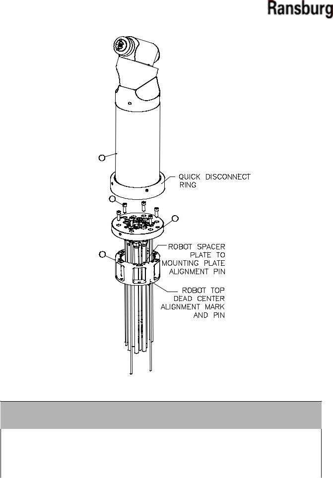
The Evolver 303 dual purge is equipped with a quick disconnect assembly. The quick disconnect feature consists of a robot plate which is permanently attached to the robot through a wrist adapter plate and a mating rear plate which is part of the Evolver 303 Dual Purge Spray Applicator assembly. The applicator is secured to the robot plate with a threaded retaining ring.
FLUID CONNECTIONS
The paint, solvent, and dump fluid tubing are connected on the back of the robot plate with stainless steel compression fittings and PFA tubing. Fluid tubing requirements are shown in the "Signal Identification Tables" in the "Installation" section.
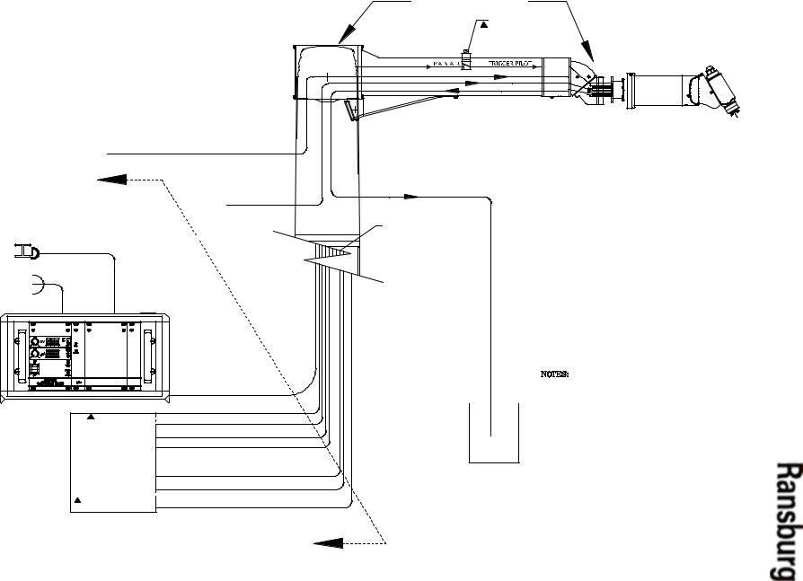
TYPICAL INSTALLATION
Figure 4 shows a typical installation of the Evolver 303 dual purge and the wiring installation of the applicator with the MicroPak.
13 |
AA-08-01.1 |

Evolver 303 Dual Purge Robotic Atomizers - Installation
|
|
|
|
|
|
|
|
|
|
|
|
|
|
EARTH GROUND |
WHITE |
RED |
BLACK |
GREEN |
BLUE |
|
YELLOW |
GRAY |
ORANGE |
|
|
|
BARE (DRAIN) |
BARE (DRAIN) |
3/4" BRAID CABLE |
N/C |
|
|
|
|
N/C |
N/C |
|
|
/CN |
N/C |
/CN |
N/C |
|
|
J3 |
|
|
|
|
|
|
|
|
|
|
|
|
|
GND. BUS |
|
|
|
|
|
|
|
|
|
|
|
|
|
|
HV |
MICROPAK
J2 |
1 |
2 |
3 |
J10 |
1 |
2 |
J6 |
1 |
2 |
3 |
||||||||
|
|
|
|
|
|
|
|
|
|
|
|
|
|
|
|
|
|
|
|
|
|
|
|
|
|
|
|
|
|
|
|
|
|
|
|
|
|
|
FACT. GND |
+24 VDC |
24 VRET |
|
+24 VDC |
24 VRET |
|
|
|
|
|
|
|
|||||
!W A R N I N G
>The power supply MUST be located outside theHAZARDOUSarea(ReferenceOSHA,NFPA-33, and your insurance company requirements.)
>User should be aware of, and adhere to, all local fire codes and ordinances.
>The user MUST provide a properly fused disconnect between the power source and the power supply which complies with appropriate codes.
>Fluid supply must be grounded per NFPA-33.
Figure 4: Low Voltage Cable Connections
AA-08-01.1 |
14 |
EQUIVALANT
15
Layout Fluid and Air Applicator Spray Purge Dual 303 Evolver 5: Figure
1.01-08-AA
LEAVE TUBING SLACK IN THE WRIST AND ELBOW
AREA TO REDUCE ROTATION STRESS.
TRIGGER SOLENOID (IF USED)
SUPPLIED BY OTHERS
PAINT SUPPLY 1 |
SOLVENT SUPPLY |
DUMP |
|
THE ROBOT IS SHOWN |
|
|
FOR REFERENCE ONLY AND IS NOT INCLUDED |
|
PAINT 1 INBOUND |
WITH THE ITW EQUIPMENT PURCHASE. |
|
|
SOLVENT INBOUND |
|
|
DUMP LINE OUT |
|
|
LUBRICATE THE TUBING BUNDLE |
|
3/4" HV GND BRAID (DEARBORN #91234 OR |
EXCESSIVELY TO EASE INSTALLATION |
|
AND EXTEND TUBING LIFE. |
||
ATTACH TO ISOLATED H.V. GND (FOR MICROPAK) |
||
|
||
INSIDE ENCLOSURE |
|
|
BUILDING STEEL/GROUND ROD |
|
120VAC AC NEUTRAL GROUND
ATTACH TO PANEL
|
|
L.V. CABLE |
|||
ANALOG SIGNALEQUIREDAND |
SHAPING AIR/ATOMIZATION AIR |
|
(GRAY) |
||
SEAL AIR/FAN AIR |
(BLUE) |
|
|
||
TRANSDUCER R |
|
|
|
|
|
ANEL |
PAINT 1 TRIGGER VALVE SIGNAL |
|
(GREEN) |
||
PAINT 1 DUMP VALVE TRIGGER SIGNAL |
(ORANGE) |
||||
SOLVENT VALVE TRIGGER SIGNAL |
(BLUE) |
||||
BEARING AIR/PAINT TRIGGER |
(YELLOW) |
||||
CONTROL P |
(MAIN AIR IF EXTERNAL TRIGGER USED) |
||||
PAINT 2 TRIGGER/PEGULATOR PILOT |
(NATURAL) |
||||
CONTROLS BY OTHERS |
|||||
(USED FOR DUAL PURGE AND REGULATED APPLICATIONS) |
|||||
|
|||||
IF USING A CAP CLEANER THE SOLVENT/AIR SHOULD NOT BE SPRAYED DIRECTLY INTO THE AIR CAP.
IF A CAP CLEANER IS USED IT MUST BE VENTED TO ATMOSPHERE WITHOUT PRESSURE BUILD UP.
Installation - Atomizers Robotic Purge Dual 303 Evolver
)
Evolver 303 Dual Purge Robotic Atomizers - Installation
APPLICATOR AND MANIFOLD ASSEMBLY
(See Figures 4 and 5)
The tubing, hose, and low voltage cable come bundled from the factory. Pull the bundle through the robot spacer plate and robot wrist carefully to prevent any cuts on the cable or hoses. Use the six
(6) socket head cap screws (76566-24C) included with the rear manifold tubing assembly to attach the rear manifold assembly ( A12283) to the robot spacer plate (see Table 1).
Connect each signal line as required per "Signal Identification Tables (Metric) Tubing Bundles" in the "Installation" section.
Rear Plate Assembly
The rear plate assembly is designed to be at ground potential when mounted to the robot plate component within the tubing bundle assembly. The air and fluid ports are compactly oriented for use in robotic applications. The interior air supplies are ported through the five (5) support rods and also directly tubed to the upper manifold assembly. On the exterior side of the rear plate, the ports are provided with o-ring seals so that the applicator can be quickly mated and secured to the robot plate
Robot Plate
The robot plate is a component of the tubing bundle assembly and intended to be permanently mounted to the robot. A wrist adapter is also available, which matches the robot's mounting configuration. The incoming air lines, fluid lines, low voltage cable, and fiberopticcableareconnectedtothefittingsprovided on the back of the robot plate. The rear plate of the applicatorassemblyissecuredtotherobotplatewith a threaded retaining ring.
Break-Away Feature (Optional)
The Evolver 303 dual purge can be converted to have a break-away feature, by replacing the five (5) stainless steel screws with five (5) special designed plastic screws (77524-00). This feature is meant to reduce the damage to the applicator, robot, etc. If a collisionoccurs,thefive(5)plasticbreak-awayscrews fail and the applicator will break free. This will leave the break-away ring and the mounting ring attached to the robot.
Power Supply and Controls
The high voltage cascade located inside the Evolver 303 dual purge is controlled by the MicroPak control unit. The low voltage ouput of the MicroPak is multiplied by the internal cascade to the high voltage level required. This eliminates the need for a high voltage cable. A low voltage cable interconnects the cascade and the MicroPak control. The MicroPak Eurocard format is designed to fit in a conventional 19-inch or 1-inch rack and requires a 24V power input at a maximum 3 amps. The MicroPak and the internal cascade will produce voltages up to 100,000VDC.
The MicroPak is designed to electronically limit current to provide safe operation in a spray booth. The voltage and current draw of the applicator are continuously displayed on the MicroPak control panel. Voltage and over-current limits are adjust-able on the front of the MicroPak. MicroPak internal safety circuits will shut down the system on over-current and cable faults.
With additional control modules, all of the functions of the Evolver 303 dual purge and MicroPak can be controlled by a programmable controller. A Serial Digital Module pneumatically controls the paint and dumpvalveslocatedontheapplicator. AnI/Omodule provides communication between these modules and the PLC.
The above modules are mounted in one 19-inch rack and interconnected through a common motherboard.
AA-08-01.1 |
16 |
Evolver 303 Dual Purge Robotic Atomizers - Installation
Robot Spacer Plate
The robot spacer plate is included with the robot manifold assembly to increase life of the tubing bundle. The extra spacing it provides increases the bend radius of the tubes and decreases the hose or cable stress at the connector.
There is only one way the spacer plate may be assembled to the mounting plate. The spacer plate has an alignment pin that may only engage in one hole position in the robot mount plate. This provides the final position to top dead center of the robot.
Six (6) robot spacer plates shown in Table 1 are available for this product.
|
TABLE 1 - SPACER PLATES |
|
|
Part # |
Description |
|
|
79107-00 ABB 5400, 5002 Robots
78983-00 Fanuc P155, 145 Robots
79131-00 Fanuc P200/P-250 Robots
A10847-00 Adapter (Kawasaki-KE610L)
A10848-00 Adapter (Motoman-PX2850)
A10849-00 Adapter (Motoman-PX2900)
A10851-00 Adapter (B & M LZ2000)
A12036-00 Adapter (ABB 5400 Enhanced Wrist)
LOW VOLTAGE CABLE INSTALLATIONS
(See Figures 6, 7, and 8)
A low voltage cable is provided to send power to the high voltage cascade in the applicator as well as sending important information during operation back to the MicroPak controls. One piece of the cable is a permanent length of approximately
72-inches (1.8 meters) from the robot plate end. The connecting cable can be ordered in various lengths depending on the distance required to reach from the robot arm to the MicroPak controller. The ends of the cables have a male and female quick disconnect end. This provides for a quick and easy removal of the cable at the robot plate if servicing or replacement is required.
It is important that the quick disconnect fitting be secured to a good ground source. The A12241-XX cable is supplied with a ground cable which can be secured to the bulkhead connector and the other end to a known ground source. The cable can also be grounded by attaching the bulkhead connector to a grounded bulkhead plate. The bulkhead plate can be no more than 1/8-inch (3.18mm) in thickness. The bracket should be made as in Figure 7 to hold the connector from turning. To mate the connectors, align the raised key section of the cable on the applicator end with the key groove of the cable that goes to the MicroPak. Push the male end into the mating connector until an audible click is heard. Tug oncabletoensurethatitislockedinplace. Toremove or disconnect the cable, pull back on the male connector shell and pull cable back at the same time. To remove this section from the robot plate, remove the applicator. Locate the set screw holding the flanged plastic 9 pin connector. Loosen with a 3/32" hex key wrench. Pull the cable out from the robot plate end. Install new cable in reverse direction, align the 9 pin connector with the alignment mark on the robot plate face and tighten set screw. Torque 5-10 lbs•in (0.56-1.13 Nm).
!W A R N I N G
>Cable connector shell must be electrically grounded. Electrical noise or other interference may result.
NOTE
> With the exception of fluid, dump, and bearing air/paint trigger, all other pilot and air supply lines should be bulkheaded and their diameters increased one nominal size. For example: atomization air should be increased to an 1/2" ID (8mm) from bulkhead plate to the volume booster.
17 |
AA-08-01.1 |

Evolver 303 Dual Purge Robotic Atomizers - Installation
|
|
NOTES |
|
NOTE |
|
|
|
|
|
|
|
|
|
|
> If the length of the fan or atomization air lines exceeds 30-ft. (10m), the lines must be upsized to 1/2" ID (12mm for metric).
NOTE
> For the dipswitch settings for the Evolver303dualpurge,referencethecurrent microPak service manual
NOTE
> Leave 12-24-inches (.30-.61m) of
extra length on all lines to prevent extreme tension being applied to these lines during robot movement. This increases tubing bundle life.
AA-08-01.1 |
18 |
Evolver 303 Dual Purge Robotic Atomizers - Installation
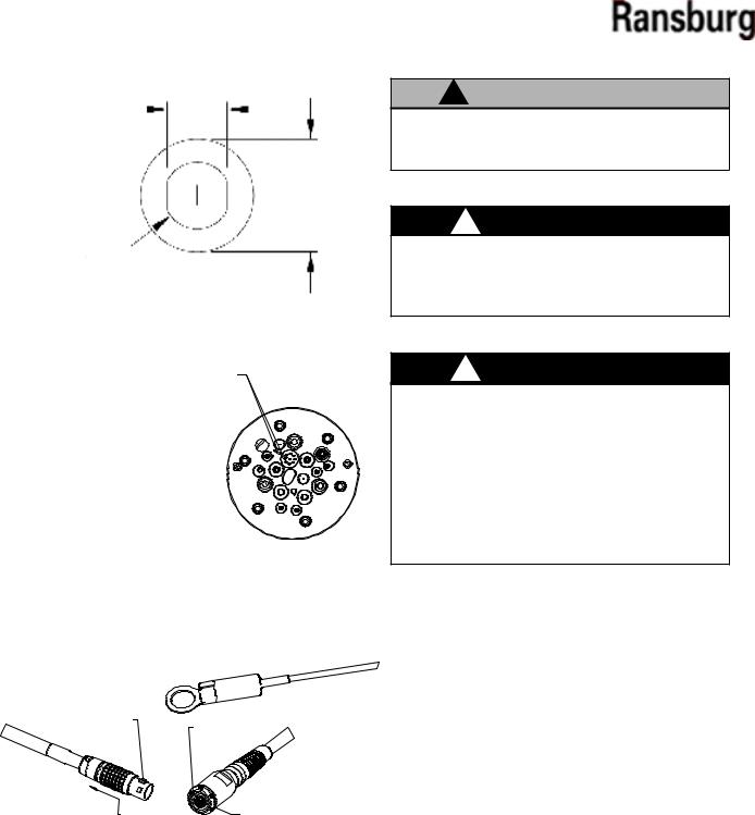
0.53"
(13.49mm)
1.00" |
(25.40mm) |
0.59"
(15.00mm)
Figure 6: Bulkhead Cut-Out Diagram
ALIGN TIMING MARKS ON ROBOT PLATE
AND LOW VOLTAGE CABLE CONNECTOR AS SHOWN.
TIGHTEN SET SCREW TO 5-10 LBS./IN (0.56-1.13 Nm) TORQUE
ROBOT PLATE (ATOMIZER SIDE)
Figure 7: Robot Plate
OPTIONAL GROUND CABLE
RAISED MALE KEY
FEMALE KEY SLOT
PUSH TO RELEASE |
CONNECT HERE TO BULKHEAD OR |
|
|
ATTACH GROUND CABLE HERE |
|
MALE CONNECTOR AND |
BULKHEAD AND MICROPAK |
|
CABLE END |
||
APPLICATOR CABLE END |
||
|
Figure 8: Quick-Disconnect Cables
!C A U T I O N
>Do not exceed 100-ft. combined length of the low voltage cables.
!W A R N I N G
>If a non-explosion proof junction box/terminal strip is used, it must be located outside the hazardous area.
!W A R N I N G
>Install and route the hoses and cable so that they are NOT exposed to temperatures in excess of 120° F. Ensure that all hose and cable bends are NOT LESS THAN a 6-inch (15cm) radius and are not subjected to more than 360° of torsional twist. Failure to comply with these parameters couldcauseequipmentmalfunctionsthatmight create HAZARDOUS CONDITIONS!
19 |
AA-08-01.1 |

Evolver 303 Dual Purge Robotic Atomizers - Installation
SIGNAL IDENTIFICATION TABLE BELLS (APPLICATORS)
Abbr. |
Description |
Color |
Tubing Material |
Tubing Size |
|
|
|
|
|
B.A/P.T |
Bearing Air (Paint Trigger) |
Yellow |
Nylon |
6mm OD X 4mm ID |
B.A RTN |
Bearing Air Return |
Yellow |
Nylon |
4mm OD X 2.7mm ID |
BRK |
Brake Air |
Orange |
Nylon |
6mm OD X 4mm ID |
DL1/DL2 |
Dump Line |
Natural |
|
10mm OD X 7mm ID |
F.O |
Fiber Optic Cable |
Natural |
Polyethylene |
1/4" OD (jacket) |
LV |
Low Voltage Cable |
Black |
N/A |
N/A |
P1.IN/P2.IN |
Paint In |
Natural |
|
5/16" OD X 3/16" ID |
P1T |
Paint 1 Trigger |
Green |
Nylon |
4mm OD X 2.7mm ID |
P2T |
Paint 2 Trigger |
Natural |
Nylon |
4mm OD X 2.7mm ID |
P1D |
Paint 1 Dump Trigger |
Silver |
Nylon |
4mm OD X 2.7mm ID |
P2D |
Paint 2 Dump Trigger |
Black |
Nylon |
4mm OD X 2.7mm ID |
SA.I/A.A |
Inner Shaping Air (Atom. Air) |
Blue |
Nylon |
8mm OD X 6mm ID |
SOL |
Solvent In |
Natural |
|
6mm OD X 4mm ID |
SA.O/F.A |
Outer Shape Air (Fan Air) |
Gray |
Nylon |
8mm OD X 6mm ID |
ST/RP |
Solvent Trigger Signal |
Blue |
Nylon |
4mm OD X 2.7mm ID |
T.A |
Turbine Air |
Natural |
Nylon |
10mm OD X 7mm ID |
AA-08-01.1 |
20 |
Evolver 303 Dual Purge Robotic Atomizers - Installation
2
3
1
4
Figure 9: Applicator and Manifold Assembly
APPLICATOR AND MANIFOLD ASSEMBLY - PARTS LIST (Figure 9)
Item # |
Part # |
Description |
Qty |
|
|
|
|
1 |
A12283-XXXXXXX |
Tubing Bundle Assembly (Metric) |
1 |
2 |
A12374-XXX |
Evolver 303 Dual Purge Spray Applicator Assembly |
1 |
3 |
76566-24C |
Screw, 1/4-20 X 3/4" Lg., SHCS |
6 |
4 |
See Table 1 |
Robot Adapter |
1 |
21 |
AA-08-01.1 |
 Loading...