

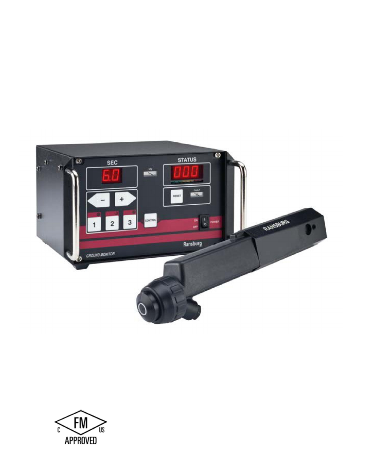
GMS
Ground Monitoring System
Ransburg
PRODUCT MANUAL
LN-9265-09.2
MODEL: A12520-XXXX
IMPORTANT: Before using this equipment, carefully
read SAFETY PRECAUTIONS, starting on page 1,
and all instructions in this manual. Keep this Service
Manual for future reference.
Product Manual Price: $50.00
LN-9265-09.2
1

NOTES
LN-9265-09.2
2

CONTENTS
Section 1: SAFETY
5
Safety Precautions
Hazards / Safeguards
Section 2: INTRODUCTION 10
FM Conguration
Inputs
Outputs
Other Considerations
Theory of Operation
Features and Benets
Specications (Environmental / Physical)
Selection Guide
Section 3: INSTALLATION 16
Mounting the Control Unit
I/O Connections
PLC Interface
AC Input Connections
Interlocks
Relay Contact Outputs
Low Voltage Cable
Section 4: OPERATION 21
Powering Up the Control Unit
Lockouts
Set-up
Calibration
Operation Sequence
Section 5: MAINTENANCE 27
Suitable Solvents for Cleaning GMS Probe
LN-9265-09.2
3

CONTENTS
Section 6: TROUBLESHOOTING 28
Fault Descriptions
Section 7: APPENDIX 31
Probe Tool Center Point Drawings
Recommended Spare Parts List
Conguration Drawing w/ Parts List
Control Unit Electrical Schematic
Control Unit Parts List
Probe Parts List
Mounting Congurations
Warranty Policies
LN-9265-09.2
4
Section 1: SAFETY
Before operating, maintaining or servicing any Ransburg electrostatic coating system, read and understand all of the
technical and safety literature for your Ransburg products. This manual contains information that is important for you
to know and understand.
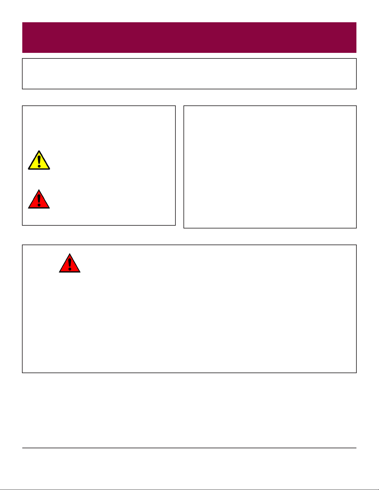
This information relates to USER SAFETY and
PREVENTING EQUIPMENT PROBLEMS. To help
you recognize this information, we use the following
symbols:
CAUTION - states information that tells
how to prevent damage to equipment or
how to avoid a situation that might cause
minor injury.
WARNING - states information to alert you
to a situation that might cause serious injury if instructions are not followed.
WARNING
• The user MUST read and be familiar with the Safety Section in this manual and the Rans-
burg safety literature therein identied.
While this manual lists standard specications and ser-
vice procedures, some minor deviations may be found
between the literature and your equipment. Differences
in local codes and plant requirements, material delivery
requirements, etc., make such variations inevitable. Compare this manual with your system installation drawings
and appropriate Ransburg equipment manuals to reconcile such differences.
Careful study and continued use of this manual will provide a better understanding of the equipment and process,
resulting in more efcient operation, longer trouble-free
service and faster, easier troubleshooting. If you do not
have the manuals and safety literature for your Ransburg
system, contact your local Ransburg representative or
Ransburg.
• This manual MUST be read and thoroughly understood by ALL personnel who operate , clean or
maintain this equipment! Special care should be taken to ensure that the WARNINGS and safety requirements for operating and servicing the equipment are followed. The user should be aware of and
adhere to ALL local building and re codes and ordinances as well as NFPA 33 SAFETY STANDARD,
2009 EDITION, prior to installing, operating, and/or servicing this equipment.
• The hazards shown on the following pages may occur during normal use of this equipment. Please
read the hazard chart beginning on page 6.
LN-9265-09.2
5

AREA HAZARD SAFEGUARDS
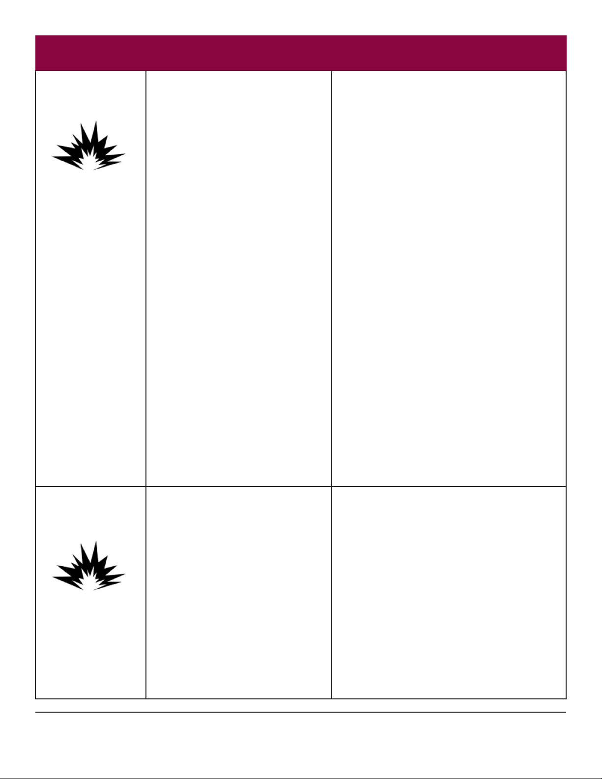
Spray Area Fire Hazard
Improper or inadequate operation and main-
tenance procedures will cause a re hazard.
Protection against inadvertent arcing that is
capable of causing re or explosion is lost if
any safety interlocks are disabled during operation. Frequent power supply shutdown
indicates a problem in the system requiring
correction.
Follow These Guidelines
Fire extinguishing equipment must be present in the
spray area and test periodically.
Spray areas must be kept clean to prevent the accumulation of combustible residues.
Smoking must never be allowed in the spray area.
The high voltage supplied to the atomizer must be
turned off prior to cleaning, ushing or maintenance.
When using solvents for cleaning:
• Those used for equipment ushing should have
ash points equal to or higher than those of the
coating material.
• Those used for general cleaning must have ash
points above 1000F (37.80C).
Spray booth ventilation must be kept at the rates
required by NFPA 33, 2009 Edition, OSHA and local
codes. Ventilation must be maintained during cleaning
operations using ammable or combustible solvents.
Electrostatic arcing must be prevented.
Non-factory replacement parts or unauthorized equip-
ment modications may cause re or injury.
If used, a key switch bypass is intended for use only
during setup operations. Production should never be
done with safety interlocks disabled.
Never use equipment for use in waterborne installations
to spray solvent based materials.
LN-9265-09.2
6
AREA HAZARD SAFEGUARDS
Spray Area Explosion
Improper or inadequate operation and
maintenance procedures may cause an
explosion.
Protection against inadvertent arcing that is
capable of causing re or explosion is lost if
any safety interlocks are disabled during operation. Frequent power supply shutdown
indicates a problem in the system requiring
correction.
Follow These Guidelines
Electrostatic arcing MUST be prevented.
All electrical equipment must be located outside Class
I or II, Division 1 or 2 hazardous areas, in accordance
with NFPA 33, 2009 Edition.
Test only in areas free of ammable or combustible
materials.
The current overload sensitivity (if equipped) MUST
be set as described in corresponding section of the
equipment manual. Protection against inadvertent
arcing that is capable of causing re or explosion is lost
if the current overload sensitivity is not properly set.
Frequent power shutdown indicates a problem with the
system which requires correction.
Always turn the control panel off prior to ushing, cleaning, or working on spray system equipment.
Ensure that the control panel is interlocked with the
ventilation system and conveyor in accordance with
NFPA 33, 2009 Edition.
Have re extinguishing equipment readily available and
tested periodically.
Spray Area Follow These Guidelines
Explosion - Incompatible Materials
Halogenated hydrocarbon solvents for
example: methylene chloride and 1,1,1,-Trichloroethane are not chemically compatible
with the aluminum that might be used in
many system components. The chemical
reaction caused by these solvents reacting
with aluminum can become violent and lead
to an equipment explosion.
Aluminum is widely used in other spray application
equipment - such as material pumps, regulators, triggering valves, etc. Halogenated hydrocarbon solvents
must never be used with aluminum equipment during
spraying, ushing, or cleaning. Read the label or data
sheet for the material you intend to spray. If in doubt as
to whether or not a coating or cleaning material is compatible, contact your coating supplier. Any other type of
solvent may be used with aluminum equipment.
LN-9265-09.2
7
AREA HAZARD SAFEGUARDS
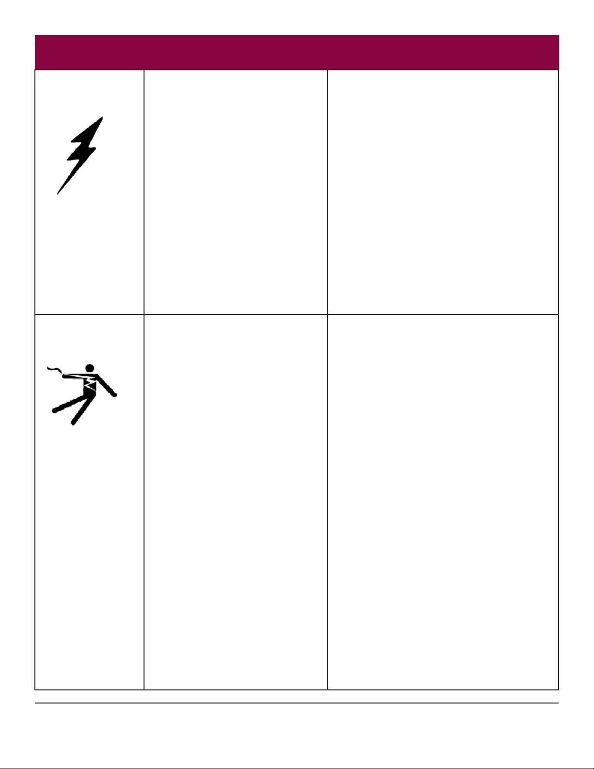
Spray Area / High Volt-
age Equipment
Electrical Equipment Follow These Guidelines
There is a high voltage device that can
induce an electrical charge on ungrounded
objects which is capable of igniting coating
materials.
Inadequate grounding will cause a spark
hazard. A spark can ignite many coating
materials and cause a re or explosion.
High voltage equipment is utilized. Arcing in
areas of ammable or combustible materials
may occur. Personnel are exposed to high
voltage during operation and maintenance.
Electrical Discharge
Electrical Discharge
Follow These Guidelines
Parts being sprayed must be supported on conveyors
or hangers and be grounded. The resistance between
the part and ground must not exceed 1 mega ohm.
All electrically conductive objects in the spray area, with
the exception of those objects required by the process
to be at high voltage, must be grounded.
Any person working in the spray area must be grounded.
Unless specically approved for use in hazardous
locations, the power supply and other electrical control
equipment must NOT be used in Class I, Division 1 or
2 locations.
All electrical equipment must be located outside Class
I or II, Division 1 or 2 hazardous areas. Refer to NFPA
33, 2009 Edition.
Protection against inadvertent arcing that
may cause a re or explosion is lost if safety
circuits are disabled during operation.
Frequent power supply shutdown indicates
a problem in the system which requires
correction.
An electrical arc can ignite coating materials
and cause a re or explosion.
Turn the power supply OFF before working on the
equipment.
Test only in areas free of ammable or combustible
material.
Testing may require high voltage to be on, but only as
instructed.
Production should never be done with the safety circuits disabled.
Before turning the high voltage on, make sure no objects are within the sparking distance.
LN-9265-09.2
8
AREA HAZARD SAFEGUARDS
Toxic Substances Mechanical Hazard
Certain material may be harmful if inhaled,
or if there is contact with the skin.
Robot Work Area Mechanical Hazard
Improper use or maintenance can lead to
hazardous conditions, particularly from un-
expected robot manipulator movement.
Follow These Guidelines
Follow the requirements of the Material Safety Data
Sheet supplied by the coating manufacturer.
Adequate exhaust must be provided to keep the air free
of accumulations of toxic materials.
Use a mask or respirator whenever there is a chance of
inhaling sprayed materials. The mask must be compatible with the material being sprayed and its concentration. Equipment must be as prescribed by an industrial
hygienist or safety expert, and be NIOSH approved.
Follow These Guidelines
Applicator adjustments or maintenance should be done
after the robot is taken out of service. Do not adjust or
repair the applicator if the robot is operating or standing
ready to start.
Refer to robot operating instructions for the procedures
to take a robot out of service.
Follow all OSHA Lockout / Tagout procedures when
performing any maintenance.
All Areas Follow These Guidelines
Improper / Inadequate Training
Improper operation or maintenance may
create a hazard.
Personnel must be properly trained in the
use of this equipment.
Personnel must be given training in accordance with
the requirements of NFPA 33, 2009 Edition.
Instructions and safety precautions must understood
prior to using this equipment.
Comply with appropriate codes governing ventilation,
re protection, operation maintenance, and housekeeping. OSHA references are sections 1910.94 and
1910.107. Also refer to NFPA 33, 2009 Edition and
your insurance company requirements.
LN-9265-09.2
9
Section 2: INTRODUCTION
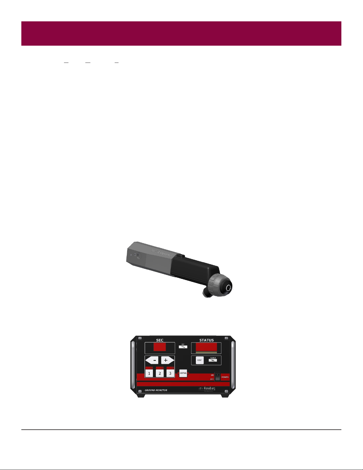
The Ransburg Ground Monitoring System (GMS) monitors the ground condition of non-metallic parts and provides
feedback, increasing the margin of safety. After scanning the part with an electrostatic charge, the GMS’s control unit
circuitry monitors several variables and compares the reading against a pre-determined standard. If the reading falls
outside of an acceptable range, the notication alarm will activate, allowing adjustments or corrections to be made, eliminating rework while increasing quality. Improper grounding can cause overspray, excess paint build-up, thin lm build,
ruined parts or a safety hazard.
The GMS consists of:
• Control Unit
• Probe Detector
• Cable
• Machine Mount Bracket
The device can be used in the spray area, FM testing is successfully complete and approval pending.
The control unit consists of an electrostatic generator, input-output signal circuitry, and is microprocessor/software based.
The probe detector contains a high voltage cascade, electrode assembly and an electrical circuit capable of providing
feedback to the control unit.
Probe Detector
Control Unit
LN-9265-09.2
10
FM CONFIGURATION
This device is FM approved when congured per the drawing shown below .
LN-9265-09.2
11

INPUTS
• 110 or 220VAC Main power input
• The control unit requires an input signal for part detection. A limit switch, photo-eye, PLC or robot signal input is
acceptable.
• The device will require eld calibration to the specic application.
OUTPUTS
• The control unit will provide a visual signal to alert the end user of the detection of an ungrounded part.
• Two contact closures (UNGROUNDED & HV ON) are provided to signal the application of HV and the detection of
an ungrounded part.
• These contacts may be hooked to a PLC, horn, or light (shown in the PLC INTERFACE section of this manual).
OTHER CONSIDERATIONS
• Designed for use on non-metallic substrates only.
• Accuracy of the system is dependent on part to probe detector distance staying consistent.
• The probe to part distance should be set to 4 inches and should not vary more than ± one (1) inch.
• Probe detector must stay clean.
• Inspect the probe detector electrode every two weeks.
LN-9265-09.2
12

THEORY OF OPERATION
• The part(s) to be detected are subjected to a high voltage electrostatic charge.
• The control unit circuitry measures the amount of energy required to charge the part during the charging time select-
ed, and compares that value with an installation specic pre-set “window”.
• If the reading falls within the end user determined pre-set setpoint, the part passes the ground test.
FEATURES AND BENEFITS
• Complete Monitoring System...consists of a control unit, ground probe, mounting bracket and low voltage cable.
• Meets Stringent Safety Requirements...FM approved for use in Class 1, Division 1 painting environments.
• Utilizes Various Input Signals for Part Detection...limit switch, photo-eye, PLC, robot signal or any 0 Volt ground
trigger detection process.
• Advanced Technology...allows user to adjust control unit for specic eld calibration..
• User-Friendly Control Unit Software...allows end user to control start timer, scan duration timer and alarm outputs.
• Easy to Read Visual Indicators...users receive simple, precise feedback regarding ground path strength.
• Versatile Model...compatible with electrostatic systems, plastic or other non-metallic surfaces.
• Versatile Ungrounded Part Alert Notication...unit provides two contact closures that may be interfaced to a PLC,
horn or light for ungrounded part alert. Contact closures included are:
1. One FAULT indicator
2. One HIGH VOLTAGE ON indicator
LN-9265-09.2
13

OPERATIONS:
• Probe distance from substrate for accurate monitoring: 4 inches +/- one inch
(100 mm +/- 25 mm)
• Minimum time for measurement and result output signal: 3.5 seconds
• Low voltage cable length: 10 meters standard
15, 20, 25 & 30 meters optional
CONTROL UNIT:
• Input voltage: 110/220 VAC
• Probe output: 85 kV maximum
• Current output: 100 µA maximum
• Height:: 5.5 inches (14.0 cm)
• Width: 8.5 inches (21.6 cm)
• Depth: 7.5 inches (19.1 cm)
SPECIFICATIONS - Environmental / Physical
PROBE:
• Weight: 7.5 lbs. (3.4 kg)
• Length: 12.1 inches (30.7 cm)
• Weight: 1 lb 10 oz (.75 kg)
• Mounting bracket weight: 1 lb 3 oz (.65 kg)
• Mounting bracket adjustment angles: 0, 30, 60 & 90°
LN-9265-09.2
14

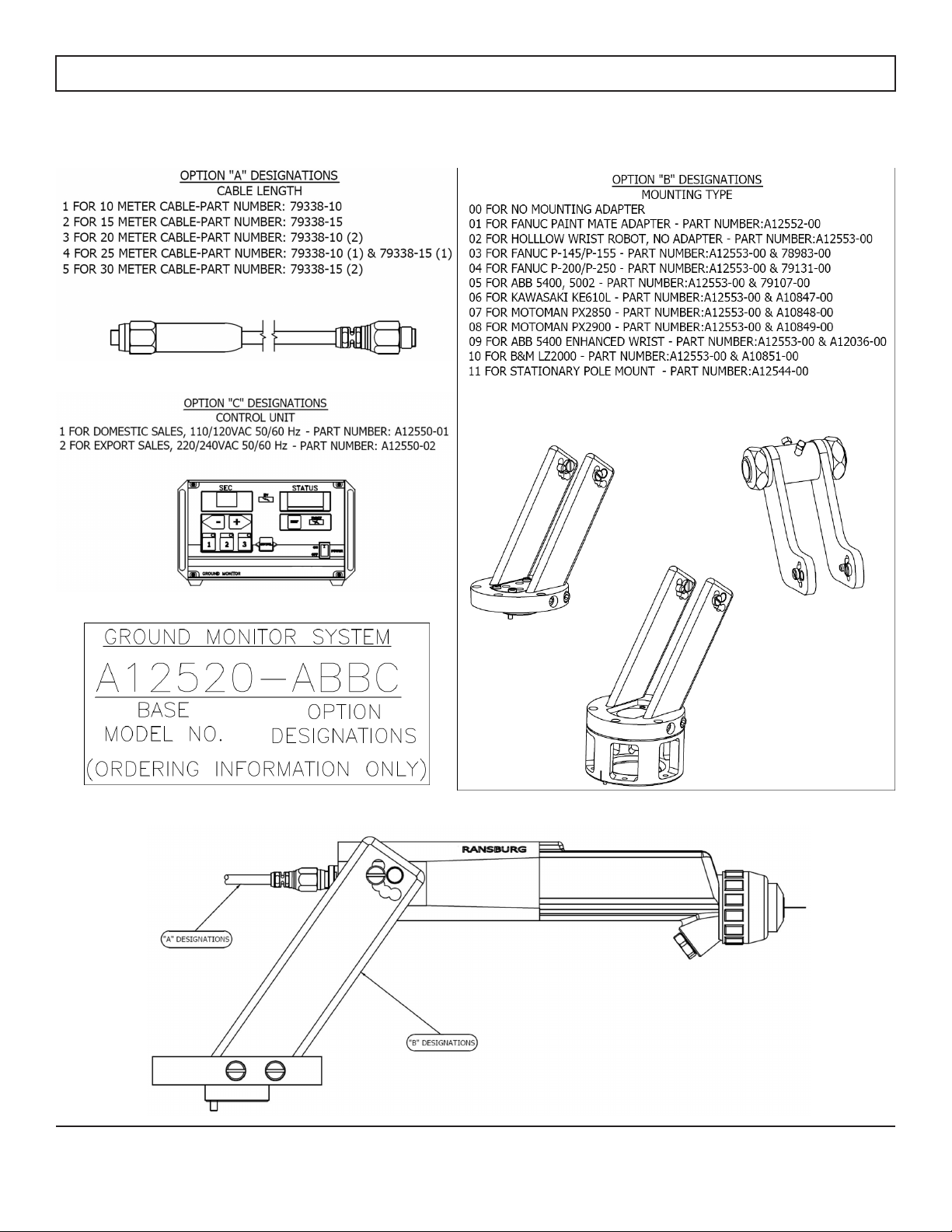
SELECTION GUIDE
A12520 - ABBC
TABLE A : LOW VOLTAGE CABLE LENGTH
1 = 10 meter
2 = 15 meter
3 = 20 meter
4 = 25 meter
5 = 30 meter
TABLE BB : MOUNTING CONFIGURATION
00 = no mounting adapter
01 = Fanuc Paint Mate
02 = hollow wrist robot (no adapter)
03 = Fanuc P-145 / P-155
04 = Fanuc P-200 / P-250
05 = ABB 5400 / 5002
06 = Kawasaki KE610L
07 = Motoman PX2850
08 = Motoman PX2900
09 = ABB 5400 enhanced wrist
10 = B&M LZ2000
11 = stationary or pole mount
TABLE C : INPUT VOLTAGE SELECTION
1 = 110/120 VAC, 50/60 Hz
2 = 220/240 VAC, 50/60 Hz
GMS Part Number Conguration
LN-9265-09.2
15

Section 3: INSTALLATION
Installation Prints:
Drawings and information contained in this section and the appendix of the manual are applicable to most installations.
However in some special cases, Ransburg may supply custom installation drawings for your specic site. It is highly
recommended that if your installation differs signicantly from the installation drawings supplied by Ransburg, you notify
your Ransburg representative to ensure that standard installation practices are not violated and to have your prints up-
dated to reect the installation accurately for future reference.
Equipment Locations:
The GMS control panel must be located outside of the hazardous area. If in doubt, contact your Ransburg representa-
tive for clarication.
MOUNTING THE CONTROL UNIT
The GMS control panel has an optional mounting kit available 79527-00. This kit allows either top mounting or back
mounting, with either swing-away or xed attachment. There are four convenient ways of mounting the enclosure assembly using the included hardware. See the Appendix section for the different mounting congurations available.
C A U T I O N
When mounting the control unit to a wall or ceiling, the 79527-00 Mounting Kit
should be used. If mounting to a non-metallic wall or ceiling, the mounting screws
must be secured to the wall or ceiling studs. If mounting to a metal wall or ceiling
(such as a spray booth) the wall or ceiling must be at least 0.050” (1.2mm) thick. In
both cases, the customer must supply the screws to attach the brackets to the wall
or ceiling. These screws should be at least 1/4” (6mm) in diameter.
I/O CONNECTIONS
For maximum noise immunity, I/O wiring should be run in conduit or cables having a foil shield with an overall braided
shield. The foil shield provides 100% shielding, while the braid provides a means of making proper 360° shield termina-
tions at the cable to cabinet connection points. To make I/O connections using shielded cable, perform the following:
1. Remove the cable grommet hardware from the I/O connector housing.
2. Route the desired length of I/O cable through the connector housing and mark 1” span of cable that passes
through connector housing to be stripped to braid.
3. Remove cable and strip marked 1” section to cable braid.
4. Slide the cable grommet hardware onto the cable.
5. Route the cable back through the connector housing and connect its wires to the desired I/O terminals inside
the GMS Control Unit or power supply.
6. Tighten the cable grommet ensuring the grommet spring makes 360° contact with the exposed braid of the
cable, for maximum noise immunity.
7. For maximum noise immunity, connect the braid of the cable to earth ground at the end opposite the control
unit or power supply.
LN-9265-09.2
16

PLC INTERFACE
The PLC interface for the Ground Monitor is very simple (Figure 1).
1. There is an input (2TB-5) to tell the process to initialize. This sinking input circuit needs a ground supplied to initialize the process.
2. The fault output is based on a non-grounded part detection. If a non-grounded part is detected a relay will close a
set of dry contacts (2TB-1 to 2TB-2) signaling a device of the users choice (light, horn, PLC, etc).
3. A “High Voltage On” output is also available to signal an external device (light, horn, PLC, etc). A set of dry contacts
(2TB-3 to 2TB-2) close when the high voltage is On. See page 20 for the maximum allowable electrical ratings for
the relay contacts.
NOTE: 2TB is common to both HV out and FAULT output
Figure 1
LN-9265-09.2
17

AC INPUT CONNECTIONS
For non-conduit installations, plug the detachable AC line cord into the receptacle on the rear of the control unit. Plug the
other end of the line cord into a properly grounded 120 volt AC outlet.
For installations where it is required to run the AC input wiring in conduit, perform the following.
1.Ensure the AC line cord is unplugged and remove the AC inlet receptacle wiring from TB1-N, TB1-L1, TB1-EARTH GROUND (see
gure 2)
2. Remove the mounting hardware from the AC inlet receptacle and remove it from the rear of the control unit.
3. Install the conduit adapter plate (supplied) in the hole where the AC inlet receptacle was removed. (see Figure 2)
4. Install the AC input wiring (0.8mm2 (18 AWG) minimum) through the conduit adapter plate using conduit and wire to TB1 as follows.
Hot/Line to TB1-L1
Neutral/Common to TB1-N
Ground to TB1-EARTH GROUND
NOTE
When using conduit to route the AC input wiring to the control unit, the last several feet of conduit attached to the control unit should be
of a exible type, such that the control unit chassis can be slid out of its enclosure for testing and set-up purposes.
Figure 2
LN-9265-09.2
18

INTERLOCKS
Interlocks required by code are as follows:
• Booth Fan Interlock - When the booth fan is on, a contact closure is made.
• Conveyor Interlock - when the conveyor is moving a contact closure is made.
W A R N I N G
Failure to connect interlocks could result in re or explosion.
W A R N I N G
ALWAYS ensure that high voltage is OFF before cleaning the applicator with solvent. NEVER clean the spray applicator with high voltage ON, as this is a severe
re hazard and risk to personnel safety.
To install the control unit interlocks perform the following:
1. Turn the control unit off and remove the fuses.
2. Loosen the front panel screws and slide the control unit chassis out.
3. Using a small blade screwdriver, remove the factory installed test jumper from TB1-L2 to TB1-L3 (Figure 3).
4. Using a shielded cable for the interlock wiring (supplied by user), route through the interlock connector on the
rear of the control unit and terminate to TB1-L2 and TB1-L3. The shielded cable must have a minimum rating of
300V and 105°C and its conductors should be 0.8mm2 (18 AWG) minimum. Secure the cable to the interlock
connector so that the shield of the cable is connected to the chassis of the enclosure.
5. Slide the chassis back in, secure the front panel screws, and replace the fuses.
NOTE:
Some codes may require the interlock wiring to be run in conduit. In this case shielded cable is not necessary, but
the conductors used should still meet the ratings specied above.
The interlock contacts (supplied by user) should be rated for at least 1-amp at 240 volts AC.
Figure 3
LN-9265-09.2
19

RELAY CONTACT OUTPUTS
A set of relay contacts for high voltage (CR1) and fault (CR2) conditions is provided at TB2-3 and TB2-1 (Figure 4). One
end of these relay contacts are connected together and also connected to a source input terminal at TB2-2 (Figure 4).
When a source voltage is present at TB2-2 and either the high voltage is on or a fault condition occurs, the source volt-
age will become available at the output end of the corresponding contact. Maximum contact ratings are as follows:
MAXIMUM CONTACT RATINGS ( RESISTIVE LOADS)
DESCRIPTION DC AC
MAX SWITCHING CAPACITY 60 W 62.5VA
MAX OPERATING CAPACITY 30 VDC 125 VAC
MAX OPERATING CURRENT 2A .5A
When wiring to TB2, use a shielded cable and route the wiring through the standard I/O connector.
An internal 24VDC source voltage is available at TB2-4. Using a jumper wire, this voltage may be connected to TB2-2
to be used as the source voltage for the relay contact outputs. In this case, the total current sourced should not exceed
1-amp (Figure 3).
Figure 4
LOW VOLTAGE CABLE
Connect the low voltage cable from the control unit to the applicator using a wrench to tighten.
CAUTION
DO NOT over tighten the low voltage connection at the applicator.
The plastic parts could be damaged.
With the GMS design, multiple cables may be connected together to create the length required,
up to a maximum of 30m (100 ft.). To connect the cables, insert the male end of one cable into the female end of the
other. Tighten both cable connectors against each other using two (2) 16mm (5/8”) open-end wrenches.
LN-9265-09.2
20

Section 4: OPERATION
POWERING UP CONTROL UNIT
When the AC power is turned on, the unit will display the set point number on the SEC display and the software revision
level in the STATUS display for 2-3 seconds.
LOCKOUTS
There are lockouts that may be done at the PC board (see Appendix section). These lockouts may be used individually
or in combination as required. If the jumpers are disconnected, the original functions are re-enabled. After changing any
jumpers, the AC power must be cycled for the new setting to take effect.
Front Panel Lockout
This feature locks out any changes to the timers from the front panel of the control unit. Default from the factory the front
panel lock out is disabled.
1. Set the timers to the desired value
2. Turn AC power off and access the interior of the control unit.
3. Place the jumper across the two (2) pins at location 16 on the main PC board (see Appendix section).
4. Close the control unit and turn AC power back on. Pressing the front panel +, -, or setpoint buttons will now
have no effect on the timers.
s using the front panel buttons. This must be set
LN-9265-09.2
21
prior to installing the jumper.
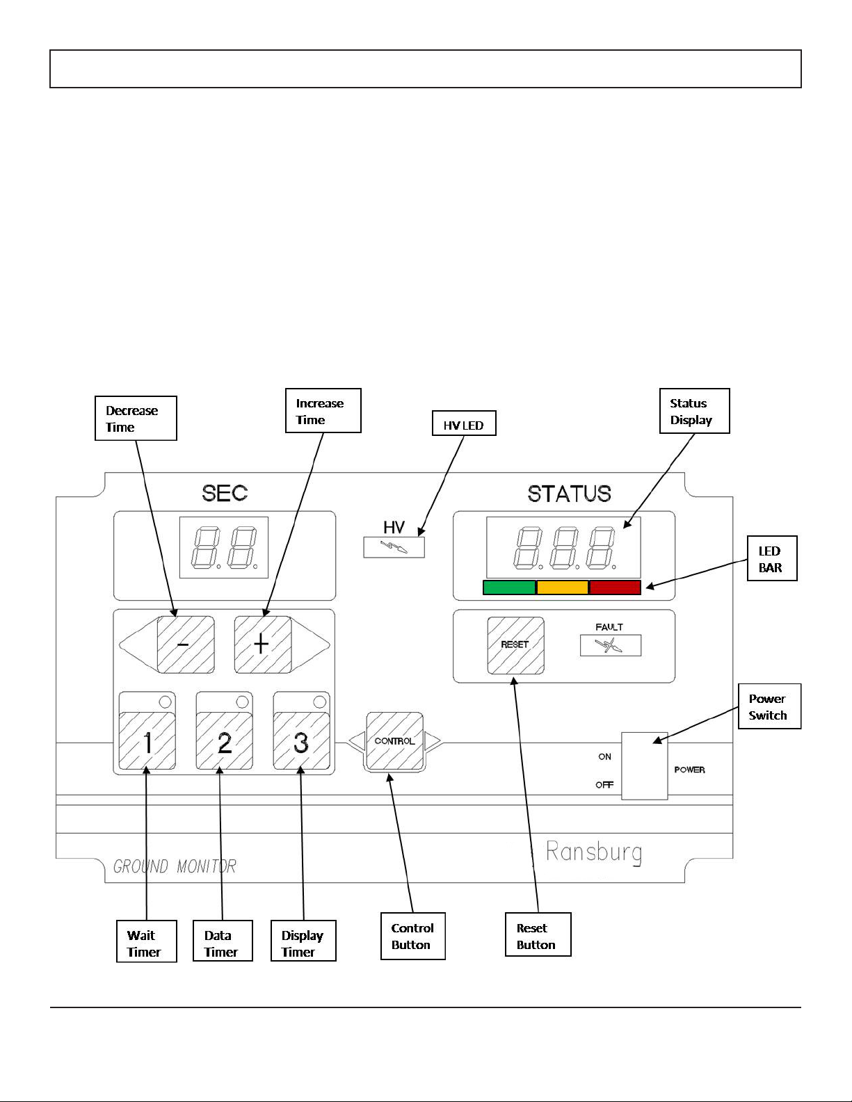
SET-UP
There are 3 timers to set before operating the Ground Monitor:
1. WAIT TIMER: The rst timer is the wait time. This will be the time to wait before turning on High Voltage
after a signal to start the process has been received. (default: 3 sec)
2. DATA TIMER: The second timer sets how long the sample will be. This is High Voltage on time. The mini-
mum settable time is 2 seconds, the average time necessary to get a good reading is 3.5 seconds. (default:
5 sec)
3. DISPLAY TIMER: The third timer sets the amount of time the result is shown for. Note: if another part input
is received during this countdown, the entire process will start over at step 1. (default: 5 sec)
LN-9265-09.2
22
CALIBRATION
1. Place the part to be checked in front of the Ground Monitor probe
2. Assure target distance is 4” (±1”)
3. Use a 1 KiloVolt (KV) megger to verify a good earth ground is present on part. The NFPA states a good ground as 1
Meg Ohm or less value.
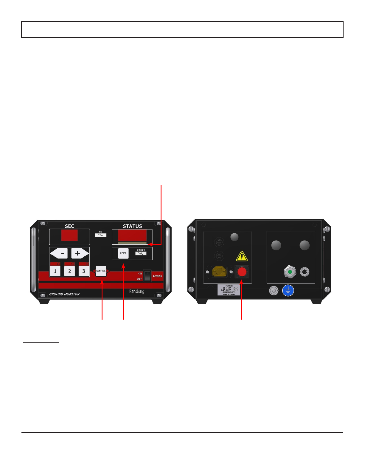
4. Press the “Control” button on the controller. The entire LED bar (green yellow, and red) under status display will light
up to indicate the unit is in calibration mode.
5. Press the red “Override” button located on the back of the controller (you may need to hold the button in for a sec-
ond). This button manually begins a cycle.
6. When the high voltage comes on allow the numbers under “Status” to settle and then press the “Control” and “Reset”
buttons at the same time to store the calibration value. The value will typically be in the rang of 60 – 80. The default
value is 55.
7. When the calibration value is accepted the LED light bar will turn off.
8. You are now ready to operate the ground monitor.
LED Bar
Back of ControllerFront of Controller
Control Button Reset Button
Special Keys:
1 and Reset - Pressing these keys together will display the saved set point in the status window. The value will display
for 5 seconds, and then go back to regular mode
2 and Reset - Pressing these keys together will display the cumulative amount of hours the HV has been on.
Override Button
3 and Reset - Will reset the set point and timers to factory default values. The unit must be turned off and back on for
the default values to take effect.
Defaults:
Timer 1 = 3.0 seconds Timer 3 = 3.0 seconds
Timer 2 = 5.0 seconds Setpoint = 55
LN-9265-09.2
23

OPERATION SEQUENCE EXAMPLE
LN-9265-09.2
24

OPERATION SEQUENCE EXAMPLE (continued)
LN-9265-09.2
25

OPERATION SEQUENCE EXAMPLE (continued)
LN-9265-09.2
26

Section 5: MAINTENANCE
SUITABLE SOLVENTS FOR CLEANING GMS PROBE
When cleaning the probe, a suitable solvent for cleaning depends on the part(s) of the applicator to be cleaned and the
material that needs to be removed. Ransburg recommends that all exterior cleaning be done with non-polar solvents
to prevent a conductive residue on critical components. We also understand that some of these solvents do not always
meet the cleaning needs of some materials. If conductive polar solvents are used to clean the applicator components, all
residues must be removed using a non-conductive non-polar solvent (i.e. high ash Naphtha). If there are any questions
as to what solvents are best for cleaning, contact your local Ransburg distributor and/or your paint supplier. The GMS
probe and low voltage cable assemblies should not be submerged or soaked in solvent. However, the outer surfaces of
these items can be wiped with a suitable cleaning solvent. All electrical components cannot be cleaned or soaked in any
solvents.
WARNING
The user MUST read and be familiar with the safety instructions in this manual.
If compressed air is used in cleaning, REMEMBER that high pressure air can be dangerous and should
NEVER be used against the body. It can blind, deafen, and may even penetrate the
skin. If used for cleaning equipment, the user should wear safety glasses.
ALWAYS turn the control unit’s power off prior to cleaning and servicing the equipment.
Be SURE the power is OFF and the system is grounded before using solvent to clean ANY
equipment.
DO NOT operate a faulty applicator!
Use of ungrounded or plastic containers may cause re or explosion.
Cleaning of the exterior surface of the applicator should be done with non-polar solvents. If
cleaning requires the use of polar solvents, the applicator should be wiped down with non-polar
solvent prior to going back into use. Using polar solvents will leave a semi-conductive lm on
the surface of the applicator that will effect efciency of the applicator and cause damage to the
components.
LN-9265-09.2
27

Section 6: TROUBLESHOOTING
FAULT DESCRIPTIONS
When a fault occurs, the Fault Indicator on the front of the control unit will light, a fault code will be displayed on the status meter. Faults can be reset by pressing the Reset button on the front of the control unit .
Cable Fault (CF)
This fault will occur if high voltage is active and the microprocessor detects that no current is being supplied to the applicator. Typical causes include a broken or improperly connected low voltage cable. Other causes could include loose
wiring in the control unit or a faulty cascade circuit in the applicator. When this fault occurs, determine the cause of the
problem, then press the reset button.
Over Voltage Fault (OU)
This fault will occur if the microprocessor detects the unit is trying to output voltage above that
required for the application. If this occurs, reset the control unit. If this fault continues to occur, replace the main PC
board.
Safety Fault (SF)
If this fault occurs, the fault indicator at the control unit will illuminate, a SF indication will show in the status display. This
fault will occur if the microprocessor detects the unit is trying to output voltage to the applicator with no trigger. If this
occurs, reset the fault from the control unit. If this fault occurs repeatedly upon reset, replace the main PC board. Other
causes of this fault include a broken ground path between the applicator and control unit caused by a faulty cable or plug
assembly.
LN-9265-09.2
28

FAULT DESCRIPTIONS (continued)
Overload Fault (OL)
This fault will occur if the current output reaches 90uA.
Remove the condition causing excess microamps and reset the fault. Typically the target distance from the probe to the
part is too close. Back up target distance and re-calibrate.
Low Current Set point Fault (LC)
This fault will occur if the set point is set below a factory preset threshold. This is to prevent unacceptable calibration
values. If this occurs use an insulation test meter with at least 1KV output (Megger), to check that the target is properly
grounded, and verify the target distance is 4 inches, then re-calibrate the unit. To recover from a LC fault the calibration
must be set very quickly, then go back and allow the voltage to settle and reset the set point again.
Current Limit Fault (CL)
This fault will occur if the output current exceeds the maximum current by more than 20 uA for 2-3 seconds. If this oc-
curs, reset the fault from the applicator or control unit. If this fault occurs repeatedly, investigate the main PC board or
applicator barrel for the cause.
LN-9265-09.2
29

FAULT DESCRIPTIONS (continued)
Voltage Feedback Fault (UF)
This fault will occur if the microprocessor detects a loss of the voltage feedback signal. If this occurs, reset the fault from
the control unit. If this fault occurs repeatedly, replace the main PC board.
Feedback Fault (FF)
This fault will occur if the microprocessor detects a loss of the current feedback signal from the applicator. If this occurs,
reset the fault from the control unit. If this fault occurs repeatedly, investigate the main PC board, cable, plug assembly,
or cascade for the cause.
LN-9265-09.2
30

Section 7: APPENDIX
4.00
5.05
16.96
20.96
18.76
22.77
0 DEGREE TOOL CENTER POINT @ 4" TARGET DISTANCE
BRACKET
X
Y
PAINT MATE
5.05 in (128.3 mm)
20.96 in (532.4 mm)
HOLLOW WRIST
22.77 in (565.7mm)
5.05 in (128.3 mm)
XYX
Y
GMS PROBE 0° TOOL CENTER POINT DRAWING
LN-9265-09.2
31

GMS PROBE 30° TOOL CENTER POINT DRAWINGS
4.00
20.34
18.53
15.08
16.88
10.40
12.41
30 DEGREE TOOL CENTER POINT @ 4" TARGET DISTANCE
BRACKET X Y
PAINT MATE
12.41 in ( 315.2 mm)
18.53 in (470.7 mm)
HOLLOW WRIST
20.34 in (516.6 mm)
12.41 in ( 315.2 mm)
30°
X
Y
LN-9265-09.2
32

GMS PROBE 60° TOOL CENTER POINT DRAWINGS
4.00
12.56
10.72
12.71
14.55
14.12
12.72
10.88
17.56
60 DEGREE TOOL CENTER POINT @ 4" TARGET DISTANCE
BRACKET
X
Y
PAINT MATE
17.57 in (446.3 mm) 12.71 in (322.8 mm)
HOLLOW WRIST
17.57 in (446.3 mm) 14.55 in (369.6 mm)
X
Y
LN-9265-09.2
33

GMS PROBE 90° TOOL CENTER POINT DRAWINGS
6.96
8.72
5.15
6.96
15.16
4.00
19.14
90 DEGREE TOOL CENTER POINT @ 4" TARGET DISTANCE
BRACKET X Y
PAINT MATE
19.14 in (486.2 mm)
5.15 in (130.8 mm)
HOLLOW WRIST
6.96 in (176.8 mm)
19.14 in (486.2 mm)
X
Y
LN-9265-09.2
34

GMS PROBE 120° TOOL CENTER POINT DRAWINGS
1.60
4.00
.24
16.72
.40
2.2
9.36
7.52
120 DEGREE TOOL CENTER POINT @ 4" TARGET DISTANCE
BRACKET X Y
PAINT MATE
16.72 in (424.7 mm)
-2.22 in (-56.4 mm)
HOLLOW WRIST
-0.41 in (-10.4 mm)
16.72 in (424.7 mm)
X
Y
LN-9265-09.2
35

CONTROL UNIT ELECTRICAL SCHEMATIC
LN-9265-09.2
36

GMS CONTROL UNIT PARTS LIST
PARTS LIST
DESCRIPTION
PART NUMBER
QTY
ITEM
CHASSIS ASS'Y., MACH., 9050
79497
11
HOLDER, FUSE76469-0222
SWITCH76434-01
1
3
LINE FILTER ASS'Y., AC
79491-00
14
FUSE, SLOWBLOW, 250VAC 1A72771-06
15
ASS'Y., OUTLET
79495-00
1
6
POWER SUPPLY,24 V79428-00
1
7
CABLE GLAND,EMC SPRINGA113557-01
1
8
NUT, EMC GLANDA11358-01
1
9
CORD, LINE76449-02
1
10
MEMBRRANE, SWITCH ASSEMBLY79343-01
111
ASS'Y., PC BOARD, GMS
79390-26
1
12
BLOCK, TERMINAL76468-04213
LABEL, TERMINAL BLOCK76463-04
114
HOLE PLUG, 9/16 DIA
72596-01
115
HOLE PLUG, 7/16 DIA
72596-11216
RECEPTACLE, FEMALE CABLE76874-02
117
ENCLOSURE ASSY, 9050 CASCADE79512
1
18
PUSHBUTTON SWITCHA12569
1
19
PROTECTIVE GUARD, PUSHBUTTON SWITCHA12570
1
20
LABEL, TERMINAL BLOCK76463-05
1
21
HANDLE, ROUND, INSTRUMENTATIONLSMM0023-02
1
22
7
17
8
16
20
19
10
13
14
4
12
13
21
18
22
549
3
1
6
9
15
16
11
LN-9265-09.2
37

GMS PROBE PARTS LIST
PARTS LIST
DESCRIPTION
PART NUMBER
QTY
ITEM
ASS'Y, BARREL, SOLO
79736-0011
GROUND MONITOR BODYA12516-00
1
2
FLUID PASSAGE PLUG, SOLO BARRELA12513-00
1
3
CASCADE ASSY, SOLO79600-01
14
PLUG ASSY, L.V.A12517-00
15
AIR CAP SWIRL AIR NOZZLE79542-00
1
6
FLUID NOZZLE, SWIRL AIR79544-00
1
7
NUT, RETAINING, AIR NOZZLE79724-00
1
8
PRESSURE REDUCER, ATOMIZING AIR, VECTOR SOLO79809-00
1
9
SLOTTED SET SCREW, NYLON
79798-04
1
10
M5 x .8 x 40 mm MACHINE SCREW
A12540-00
3
11
NEEDLE SHROUDA12519-00
112
KIT, NEEDLE SHAFT ASSEMBLY79853-01113
REAR LABEL
A12568-00
1
14
16
CABLE W/ MOLDED CONNECTORS
79338-XX
1
16
GREASE, DI-ELECTRIC
LSCH0009-00
1
17
17
GASKET, BARREL79832-201
1
15
11
15
14
2
1
9
8
6
3
4
13
12
10
5
7
LN-9265-09.2
38

PANEL MOUNTING CONFIGURATIONS
79490-0025
79488-00
1
4
79489-001
3
79493-008
2
---
------
DESCRIPTION
PART NUMBER
QTY
ITEM
Parts List
5
2
4
5
2
5
3
2
5
2
2
5
2
3
5
2
5
2
4
5
--SCREW, PAN HEAD, 8-32 PHILLIPS, S.S.
BRACKET, MACH., 9050 CASCADE
HINGE, MACH., 9050 CASCADE ENCLOSURE
BRACKET, WALL MOUNT, 9050 CASCADE
LOCK WASHER,STD., HELICAL SPRING
SERVICE INSTRUCTION
SI-0222-06
7734-03
1
6
7
6
GMS ENCLOSURE
REF.
GMS ENCLOSURE
REF.
GMS ENCLOSURE
REF.
GMS ENCLOSURE
REF.
LN-9265-09.2
39

FRONT PANEL LOCKOUT
LN-9265-09.2
40

MANUAL CHANGE SUMMARY
This manual was published to supersede Service
manual LN-9265-09.1 Ground Monitor System to
make the following changes:
1. Update relay contact specications, page 20.
2. OL fault description updated. Cannot be disabled in
GMS revision 1.00 or 1.01 software. Page 29.
3. GMS cascade part number now 79600-01. page 38
4. Update appendix drawings.
5.
LN-9265-09.2
41

WARRANTY POLICIES
LIMITED WARRANTY
Ransburg will replace of repair without charge any part/or equipment that fails within the specied time (see below) because of faulty workmanship or material, provided that the equipment has been used and maintained in accordance with
Ransburg’s written safety and operating instructions, and has been used under normal operating conditions. Normal
wear items are excluded.
THE USE OF OTHER THAN RANSBURG APPROVED PARTS VOIDS ALL WARRANTIES.
SPARE PARTS: One hundred and eighty (180) days from date of purchase, except for rebuilt parts (any part number
ending in “R”) for which the warranty period is ninety (90) days.
EQUIPMENT: When purchased as a complete unit, (i.e. guns, power supplies, control units, etc.), is one (1) year from
date of purchase.
WRAPPING THE APPLICATOR IN PLASTIC WILL VOID THIS WARRANTY.
RANSBURG’S ONLY OBLIGATION UNDER THIS WARRANTY IS TO REPLACE PARTS THAT HAVE FAILED BECAUSE OF FAULTY WORKMANSHIP OR MATERIALS. THERE ARE NO IMPLIED WARRANTIES NOR WARRANTIES OF EITHER MERCHANTABILITY OR FITNESS FOR A PARTICULAR PURPOSE. RANSBURG ASSUMES NO
LIABILITY FOR INJURY, DAMAGE TO PROPERTY OR FOR CONSEQUENTIAL DAMAGES FOR LOSS OF GOODWILL OR PRODUCTION OR INCOME, WHICH RESULT FROM USE OR MISUSE OF THE EQUIPMENT BY PURCHASER OR OTHERS.
EXCLUSIONS:
If, in Ransburg’s opinion the warranty item in question, or other items damaged by this part was improperly installed,
operated or maintained, Ransburg will assume NO responsibility for repair or replacement of the item or items. The
purchaser, therefore will assume all responsibility for any cost of repair or replacement and service related costs if applicable.
LN-9265-09.2
42

NOTES
LN-9265-09.2
43

Product Manual Price: $50.00 (U.S.)
Manufacturing
1910 North Wayne Street
Angola, Indiana 46703-9100
Telephone: 260-665-8800
Fax: 260-665-8516
Technical Service - Assistance
320 Phillips Ave.
Toledo, Ohio 43612-1493
Telephone (toll free): 800-233-3366
Telephone: 419-470-2021
Fax: 419-470-2040
Technical Support Representatives can direct you to the appropriate telephone number for ordering spare parts.
© 2013 Ransburg. All rights reserved.
Models and specications subject to change without notice.
Form No. LN-9265-09.2
Litho in U.S.A.
06/12
LN-9265-09.2
44
 Loading...