

Ransburg
EVOLVER 303TM SOLVENTBORNE
SERVICE MANUAL
AA-07-03.2
March - 2013
ROBOTIC ATOMIZERS
MODEL: A11976-XXX
IMPORTANT: Before using this equipment, carefully read SAFETY PRECAUTIONS, starting on
page 1, and all instructions in this manual. Keep
this Service Manual for future reference.
With
Technology
Service Manual Price: €40.00 (Euro)
$50.00 (U.S.)

Ransburg
CONTENTS
SAFETY:
Evolver 303 Robotic Atomizers - Safety
PAGE
1-5
SAFETY PRECAUTIONS............................................................................................................
HAZARDS / SAFEGUARDS.......................................................................................................
INTRODUCTION:
RANSBURG ELECTROSTATIC PROCESS...............................................................................
EVOLVER 303 SOLVENTBORNE SPRAY APPLICATORS......................................................
SPECIFICATIONS.......................................................................................................................
EVOLVER 303 APPLICATOR ASSEMBLY................................................................................
EVOLVER 303 TUBING BUNDLE ASSEMBLY (ENGLISH).....................................................
EVOLVER 303 TUBING BUNDLE ASSEMBLY (METRIC).......................................................
EVOLVER 303 SOLVENTBORNE ROBOTIC APPLICATORS................................................
FEATURES..................................................................................................................................
A11976-XXX EVOLVER SPRAY APPLICATOR ASSEMBLY..................................................
TOOL CENTER-POINT COMPARISONS TABLE.....................................................................
INSTALLATION:
EVOLVER 303 ROBOTIC ATOMIZER INSTALLATION............................................................
POWER SUPPLY ASSEMBLY...................................................................................................
MOUNTING..................................................................................................................................
ELECTRICAL AND FIBER OPTIC CONNECTIONS.................................................................
FLUID CONNECTIONS...............................................................................................................
TYPICAL INSTALLATION...........................................................................................................
LOW VOLTAGE CABLE CONNECTIONS.................................................................................
EVOLVER SPRAY APPLICATOR AIR AND FLUID LAYOUT..................................................
APPLICATOR AND MANIFOLD ASSEMBLY............................................................................
LOW VOLTAGE CABLE INSTALLATIONS................................................................................
SIGNAL IDENTIFICATION TABLES (ENGLISH/METRIC).......................................................
APPLICATOR AND MANIFOLD ASSEMBLY / PARTS LIST....................................................
SPRAY / BELL APPLICATOR TRIGGERING............................................................................
TUBING BUNDLE INSTALLATION............................................................................................
BUNDLE LUBRICATION.............................................................................................................
1
2-5
6-14
6
6-7
8
9
10
11
12
13
14
14
15-24
15
15
15
15
15
15
16
17
18-19
19-20
20
21
22
23
23-24
OPERATION:
SPRAY APPLICATOR CONTROLS...........................................................................................
HVLP SPRAY...............................................................................................................................
FLUID VALVE CONTROLS.........................................................................................................
SINGLE PURGE SPRAYING......................................................................................................
(Continued On Next Page)
AA-07-03.2
25-27
25
25-26
26
26-27

Evolver 303 Robotic Atomizers - Safety
MAINTENANCE:
Ransburg
PAGE
28-50
ROUTINE MAINTENANCE SCHEDULE....................................................................................
PROCEDURES............................................................................................................................
SPRAY HEAD REMOVAL / ASSEMBLY / PARTS LIST............................................................
SERVICE......................................................................................................................................
SPRAY HEAD ASSEMBLY..........................................................................................................
79138 EVOLVER APPLICATOR HEAD ASSEMBLY / PARTS LIST........................................
REMOVING SPRAY APPLICATOR FROM THE
REAR MANIFOLD ASSEMBLY...................................................................................................
EVOLVER 303 60° SINGLE HEAD APPLICATOR
ASSEMBLY / PARTS LIST...........................................................................................................
DISASSEMBLY OF A11981 SPRAY APPLICATOR
ASSEMBLY / PARTS LIST...........................................................................................................
CASCADE WIRE PLUG ASSEMBLY..........................................................................................
LOW VOLTAGE CABLE REMOVAL / PARTS LIST...................................................................
A11241-01 SINGLE PURGE VALVE MANIFOLD
DISASSEMBLY / PARTS LIST.....................................................................................................
TROUBLESHOOTING GUIDE....................................................................................................
PARTS IDENTIFICATION:
A11976 SPRAY APPLICATOR ASSEMBLY / PARTS LIST..........................................................
79138-01 SPRAY HEAD ASSEMBLY / PARTS LIST...................................................................
79138-02 HVLP SPRAY HEAD ASSEMBLY PARTS LIST...........................................................
79179-00 SINGLE HEAD 60° / PARTS LIST...............................................................................
79243-00 DUAL HEAD 60° / PARTS LIST...................................................................................
79180-00 SINGLE HEAD 90° / PARTS LIST...............................................................................
79224-00 DUAL HEAD 90° / PARTS LIST...................................................................................
A11981 MANIFOLD ASSEMBLY / PARTS LIST.........................................................................
A11206-01 REAR PLATE ASSEMBLY (SINGLE PURGE) /
PARTS LIST.................................................................................................................................
A12000-XXXXX TUBING BUNDLE ASSEMBLY (ENGLISH) / PARTS LIST...............................
A12000-XXXXX TUBING BUNDLE ASSEMBLY MODEL
IDENTIFICATION (ENGLISH).....................................................................................................
A11061-XXXXX TUBING BUNDLE ASSEMBLY (METRIC) / PARTS LIST.................................
A11061-XXXXX TUBING BUNDLE ASSEMBLY MODEL
IDENTIFICATION (METRIC).......................................................................................................
A10406 OR LECU5004 MICROPAK CONTROL UNIT...............................................................
ACCESSORIES AND SERVICE KITS........................................................................................
REPAIR KITS..............................................................................................................................
SERVICE PARTS........................................................................................................................
LUBRICANTS AND SEALERS...................................................................................................
RECOMMENDED SPARE PARTS.............................................................................................
28-29
29-30
31-32
33
33-35
36-37
38
39
40-41
42
43-45
46
47-50
51-80
51-52
53-54
55
56
56
57
57
58-59
60
61-63
64-66
67-69
70-72
73
73-75
76
77
77
78-80
WARRANTY POLICIES:
LIMITED WARRANTY..................................................................................................................
81
81
AA-07-03.2
Evolver 303 Robotic Atomizers - Safety
SAFETY
Ransburg
SAFETY PRECAUTIONS
Before operating, maintaining or servicing any
Ransburg electrostatic coating system, read and
understand all of the technical and safety literature for your Ransburg products. This manual
contains information that is important for you to
know and understand. This information relates to
USER SAFETY and PREVENTING EQUIPMENT
PROBLEMS. To help you recognize this information, we use the following symbols. Please pay
particular attention to these sections.
A WARNING! states information to alert you
to a situation that might cause serious injury
if instructions are not followed.
A CAUTION! states information that tells how
to prevent damage to equipment or how to
avoid a situation that might cause minor injury.
A NOTE is information relevant to the procedure in progress.
W A R N I N G
!
The user MUST read and be familiar with
the Safety Section in this manual and the
Ransburg safety literature therein identied.
This manual MUST be read and thor-
oughly understood by ALL personnel who
operate, clean or maintain this equipment!
Special care should be taken to ensure that
the WARNINGS and safety requirements for
operating and servicing the equipment are
followed. The user should be aware of and
adhere to ALL local building and re codes
and ordinances as well as NFPA-33 SAFETY STANDARD, LATEST EDITION, prior
to installing, operating, and/or servicing this
equipment.
W A R N I N G
!
While this manual lists standard specications
and service procedures, some minor deviations
may be found between this literature and your
equipment. Differences in local codes and plant
requirements, material delivery requirements,
etc., make such variations inevitable. Compare
this manual with your system installation drawings and appropriate Ransburg equipment manuals to reconcile such differences.
Careful study and continued use of this manual will
provide a better understanding of the equipment
and process, resulting in more efcient operation,
longer trouble-free service and faster, easier
troubleshooting. If you do not have the manuals
and safety literature for your Ransburg system,
contact your local Ransburg representative or
Ransburg.
The hazards shown on the following pag-
es may occur during the normal use of this
equipment. Please read the hazard chart beginning on page 2.
1
AA-07-03.2
Ransburg
Evolver 303 Robotic Atomizers - Safety
AREA
Tells where hazards
may occur.
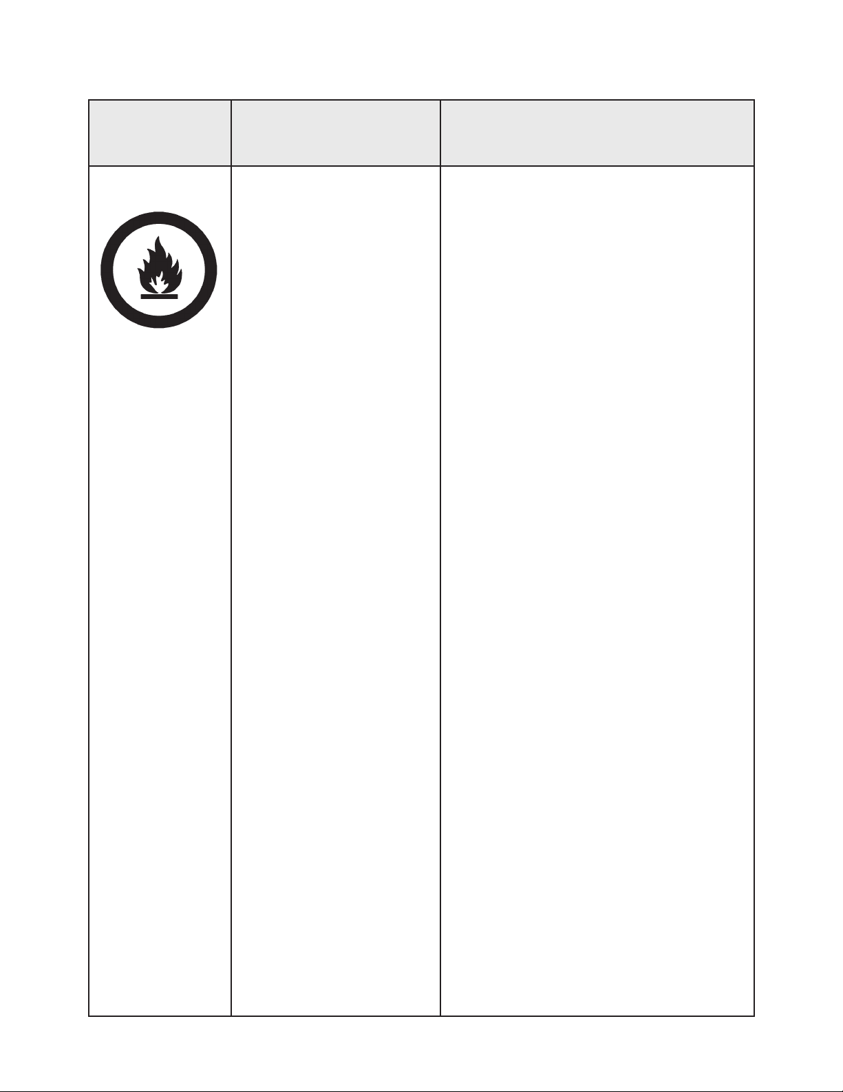
Spray Area
HAZARD
Tells what the hazard is.
Fire Hazard
Improper or inadequate
operation and maintenance
procedures will cause a re
hazard.
Protection against inadvertent arcing that is capable of
causing re or explosion is
lost if any safety interlocks
are disabled during operation. Frequent Power Supply
or Controller shutdown indicates a problem in the system
requiring correction.
SAFEGUARDS
Tells how to avoid the hazard.
Fire extinguishing equipment must be present in
the spray area and tested periodically.
Spray areas must be kept clean to prevent the
accumulation of combustible residues.
Smoking must never be allowed in the spray
area.
The high voltage supplied to the atomizer must
be turned off prior to cleaning, ushing or maintenance.
When using solvents for cleaning:
• Those used for equipment ushing should
have ash points equal to or higher than
those of the coating material.
• Those used for general cleaning must have
ash points above 100°F (37.8°C).
Spray booth ventilation must be kept at the rates
required by NFPA-33, OSHA, country, and local
codes. In addition, ventilation must be maintained during cleaning operations using ammable or combustible solvents.
Electrostatic arcing must be prevented. Safe
sparking distance must be maintained between
the parts being coated and the applicator. A distance of 1 inch for every 10KV of output voltage
is required at all times.
Test only in areas free of combustible material.
Testing may require high voltage to be on, but
only as instructed.
Non-factory replacement parts or unautho-
rized equipment modications may cause re or
injury.
If used, the key switch bypass is intended for
use only during setup operations. Production
should never be done with safety interlocks disabled.
Never use equipment intended for use in waterborne installations to spray solvent based materials.
The paint process and equipment should be
set up and operated in accordance with NFPA33, NEC, OSHA, local, country, and European
Health and Safety Norms.
AA-07-03.2
2
Evolver 303 Robotic Atomizers - Safety
Ransburg
AREA
Tells where hazards
may occur.
Spray Area
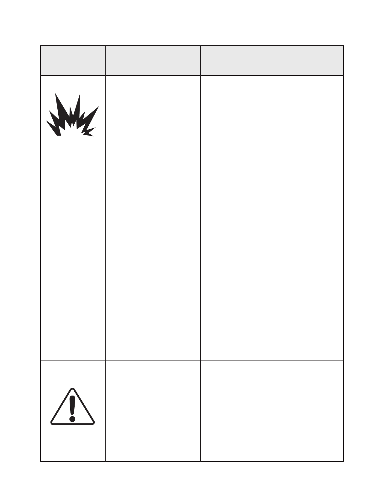
HAZARD
Tells what the hazard is.
Explosion Hazard
Improper or inadequate operation and maintenance proce-
dures will cause a re hazard.
Protection against inadvertent
arcing that is capable of caus-
ing re or explosion is lost if
any safety interlocks are disabled during operation.
Frequent Power Supply or
Controller shutdown indicates
a problem in the system requiring correction.
SAFEGUARDS
Tells how to avoid the hazard.
Electrostatic arcing must be prevented. Safe
sparking distance must be maintained between
the parts being coated and the applicator. A distance of 1 inch for every 10KV of output voltage
is required at all times.
Unless specically approved for use in hazardous locations, all electrical equipment must be
located outside Class I or II, Division 1 or 2
hazardous areas, in accordance with NFPA-33.
Test only in areas free of ammable or combustible materials.
The current overload sensitivity (if equipped)
MUST be set as described in the corresponding section of the equipment manual. Protection against inadvertent arcing that is capable
of causing re or explosion is lost if the current
overload sensitivity is not properly set. Frequent power supply shutdown indicates a problem in the system which requires correction.
General Use and
Maintenance
Improper operation or maintenance may create a hazard.
Personnel must be properly
trained in the use of this equipment.
Always turn the control panel power off prior to
ushing, cleaning, or working on spray system
equipment.
Before turning high voltage on, make sure no
objects are within the safe sparking distance.
Ensure that the control panel is interlocked with
the ventilation system and conveyor in accordance with NFPA-33, EN 50176.
Have re extinguishing equipment readily available and tested periodically.
Personnel must be given training in accordance
with the requirements of NFPA-33, EN 60079-0.
Instructions and safety precautions must be
read and understood prior to using this equipment.
Comply with appropriate local, state, and national codes governing ventilation, re protection, operation maintenance, and housekeeping. Reference OSHA, NFPA-33, EN Norms
and your insurance company requirements.
3
AA-07-03.2
Ransburg
Evolver 303 Robotic Atomizers - Safety
AREA
Tells where hazards
may occur.
Spray Area /
High Voltage
Equipment
HAZARD
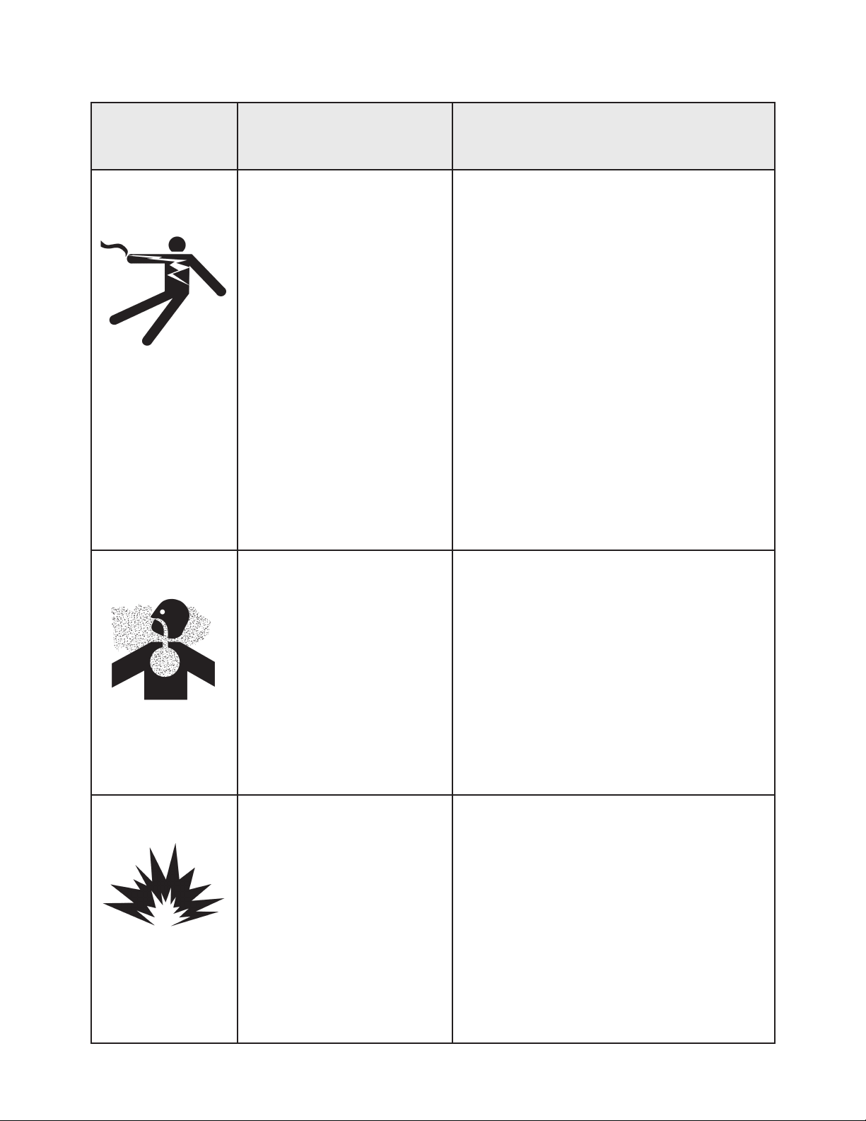
Tells what the hazard is.
Electrical Discharge
There is a high voltage device
that can induce an electrical
charge on ungrounded objects
which is capable of igniting
coating materials.
Inadequate grounding will
cause a spark hazard. A
spark can ignite many coating
materials and cause a re or
explosion.
SAFEGUARDS
Tells how to avoid the hazard.
Parts being sprayed and operators in the spray
area must be properly grounded.
Parts being sprayed must be supported on conveyors or hangers that are properly grounded. The resistance between the part and earth
ground must not exceed 1 meg ohm. (Refer to
NFPA-33.)
Operators must be grounded. Rubber soled insulating shoes should not be worn. Grounding
straps on wrists or legs may be used to assure
adequate ground contact.
Operators must not be wearing or carrying any
ungrounded metal objects.
When using an electrostatic handgun, operators
must assure contact with the handle of the applicator via conductive gloves or gloves with the
palm section cut out.
NOTE: REFER TO NFPA-33 OR SPECIFIC
COUNTRY SAFETY CODES REGARDING
PROPER OPERATOR GROUNDING.
All electrically conductive objects in the spray
area, with the exception of those objects required by the process to be at high voltage, must
be grounded. Grounded conductive ooring
must be provided in the spray area.
Always turn off the power supply prior to ushing, cleaning, or working on spray system equipment.
Unless specically approved for use in hazardous locations, all electrical equipment must be
located outside Class I or II, Division 1 or 2 hazardous areas, in accordance with NFPA-33.
AA-07-03.2
4
Evolver 303 Robotic Atomizers - Safety
Ransburg
AREA
Tells where hazards
may occur.
Electrical
Equipment
HAZARD
Tells what the hazard is.
Electrical Discharge
High voltage equipment is utilized in the process. Arcing
in the vicinity of ammable or
combustible materials may oc-
cur. Personnel are exposed to
high voltage during operation
and maintenance.
Protection against inadvertent
arcing that may cause a re or
explosion is lost if safety circuits
are disabled during operation.
Frequent power supply shutdown indicates a problem in the
system which requires correction.
An electrical arc can ignite coat-
ing materials and cause a re or
explosion.
SAFEGUARDS
Tells how to avoid the hazard.
Unless specically approved for use in hazardous locations, the power supply, control cabinet,
and all other electrical equipment must be located outside Class I or II, Division 1 and 2 hazardous areas in accordance with NFPA-33 and EN
50176.
Turn the power supply OFF before working on
the equipment.
Test only in areas free of ammable or combustible material.
Testing may require high voltage to be on, but
only as instructed.
Production should never be done with the safety
circuits disabled.
Before turning the high voltage on, make sure no
objects are within the sparking distance.
Toxic Substances
Spray Area
Certain material may be harmful
if inhaled, or if there is contact
with the skin.
Explosion Hazard –
Incompatible Materials
Halogenated hydrocarbon sol-
vents for example: methylene
chloride and 1,1,1,-Trichloroethane are not chemically
compatible with the aluminum
that might be used in many system components. The chemical
reaction caused by these solvents reacting with aluminum
can become violent and lead to
an equipment explosion.
Follow the requirements of the Material Safety
Data Sheet supplied by coating material manufacturer.
Adequate exhaust must be provided to keep the
air free of accumulations of toxic materials.
Use a mask or respirator whenever there is a
chance of inhaling sprayed materials. The mask
must be compatible with the material being
sprayed and its concentration. Equipment must
be as prescribed by an industrial hygienist or
safety expert, and be NIOSH approved.
Aluminum is widely used in other spray application equipment - such as material pumps,
regulators, triggering valves, etc. Halogenated
hydrocarbon solvents must never be used with
aluminum equipment during spraying, ushing,
or cleaning. Read the label or data sheet for the
material you intend to spray. If in doubt as to
whether or not a coating or cleaning material is
compatible, contact your coating supplier. Any
other type of solvent may be used with aluminum
equipment.
5
AA-07-03.2

Ransburg
INTRODUCTION
Evolver 303 Robotic Atomizers - Introduction
THE RANSBURG
ELECTROSTATIC
PROCESS
This process is a method for electrostatically applying coatings to objects. A power supply produces
a high voltage charge which is supplied to the
applicator, creating an electrostatic eld between
the applicator and the target object. The target
is electrostatically grounded through its support
which may be either stationary or moving.
A regulated uid system delivers coating material
to the applicator, where it is atomized forming
a spray mist. There, under the inuence of the
electrostatic eld, the atomized coating becomes
electrostatically charged. The charged particles
are attracted to and deposited on the grounded
target object. The forces between the charged
particles and the target are sufcient to turn overspray around and deposit it on the back surface
of the target. Therefore, a higher percentage of
the spray is deposited.
EVOLVER 303™
SOLVENTBORNE SPRAY
APPLICATORS
The Evolver 303 Spray Applicators System
will allow for the use of spray applicators or bell
applicators with minimal required down-time
during the switching process. This system can
also operate as a spray applicator system only
that later can be upgraded to allow for bell applicators to be used. Lastly, this system can
allow a user currently possessing an RMA-303
bell system to use spray applicators as well, with
minimal conver-sion required. The Evolver 303
Solventborne Applicator line consists of both
60° and 90° single and dual-headed 100 kV automatic electrostatic applicators. Developed for
use on robots, the Evolver 303 spray applicator
incorporates a unique 1/3 turn quick-disconnect
spray head and a one piece slide over manifold
cover, providing the user an efcient tool for the
electrostatic application of coatings.
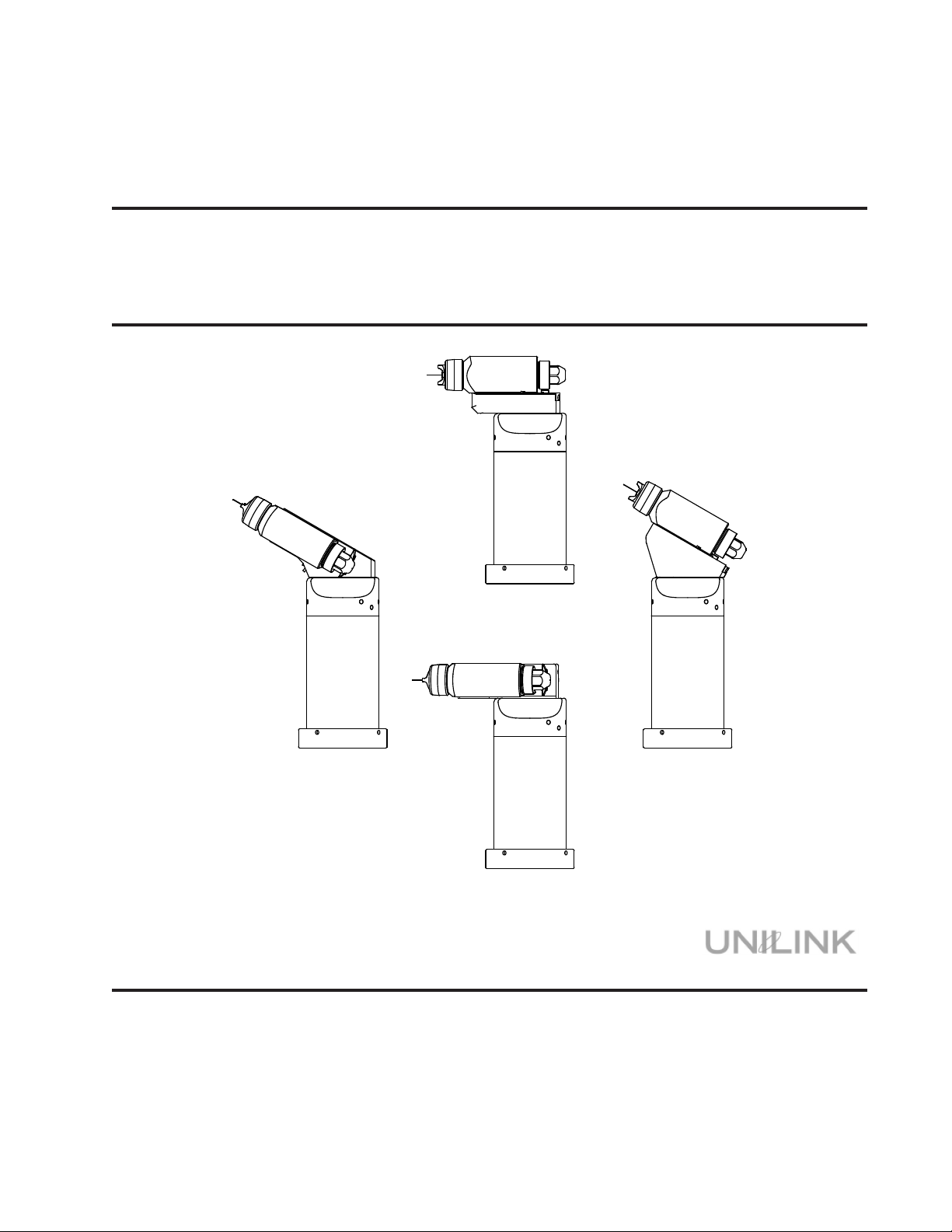
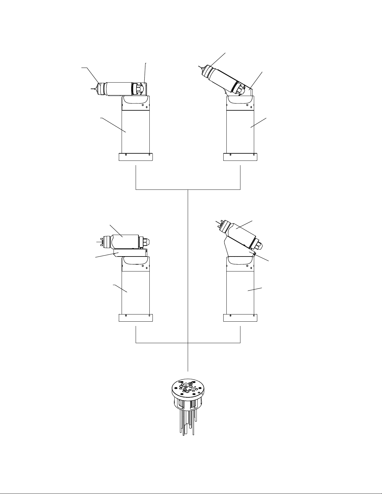
There are two single head models of the Evolver
303 Applicator (see Figure 1). Each model differs
in the applicator to axis orientation of the spray
head. These models are:
A11976-0XX 60° Single Head
A11976-1XX 90° Single Head
Two dual-head versions of the Evolver 303 Applicator are also available (see Figure 1). The
dual headed applicators are primarily used where
high volume uid delivery is required. The dual
headed applicator is available in two different
congurations as follows:
A11976-2XX 60° Dual Head
A11976-3XX 90° Dual Head
AA-07-03.2
6

Evolver 303 Robotic Atomizers - Introduction
Ransburg
The Evolver 303 Spray Applicator System consists
of four major components:
1. Quick-Disconnect Spray Head
2. Gun Head Mounting Block Assembly
3. Valve Manifold Assembly (Includes the High
Voltage Cascade with a Quick-Disconnect
Ring)
4. Rear Tubing Manifold Assembly (both English
and Metric)
The spray head(s) and valve manifold contain
the uid, air, and high voltage passages. All uid
passages contain stainless steel and/or nylon
ttings, compatible with halogenated hydrocarbon solvents. The robot manifold incorporates
stainless steel uid connections.
The high voltage cascade is entirely encapsulat-
ed with a solvent resistant epoxy. This cascade
generates voltages up to 100 kV fed by a low
voltage cable.
NOTES
There are three sources for the high voltage
supply to the Evolver 303 Applicators:
• MicroPak™ Control Unit (LECU5004)
• Stand-alone control/power supply unit
(A10406)
• MicroPakTM Control Unit (LECU5004-31)
The MicroPak Power Supply Control unit provides
a low voltage signal through the robot manifold to
the spray applicator. The high voltage cascade
located within the applicator converts the low
voltage DC signal to a high voltage electrostatic
output.
7
AA-07-03.2
Ransburg
SPECIFICATIONS
Evolver 303 Robotic Atomizers - Introduction
Environmental/Physical
Robot/Mounting Compatibility:
All hollow wrist robots
Applicator Control Unit:
MicroPak Control Unit - LECU5004-31
Stand-Alone Control Unit - A10406
Operating Temperature
Range: 55°F (12.8°C) - 131°F (55°C)
Weight
Single-Headed:
60° 7.44 lbs. (3.37 Kg)
90° 7.13 lbs. (3.23 Kg)
Dual-Headed:
60° 9.33 lbs. (4.23 Kg)
90° 9.18 lbs. (4.16 Kg)
Manifold:
A11981-XX 5.24 lbs. (2.38 Kg)
(No tubing or cable)
Length
Single-Headed:
60° 15.1 in. (38.4cm)
90° 12.2 in. (36.0cm)
Dual-Headed:
60° 14.2 in. (36.1cm)
90° 11.0 in. (27.9cm)
Tubing Manifolds (English):
A12000-0XXXXXX Air Tubing not
included
A12000-1XXXXXX 15 ft.
A12000-2XXXXXX 30 ft.
Tubing Manifolds (Metric):
A11061-0XXXXXX Air Tubing not
included
A11061-1XXXXXX 4 1/2m (15 ft.)
A11061-2XXXXXX 9m (30 ft.)
Electrical Requirements
Output Voltage: 30-100 kV
Output Range: 0-85 µA
Paint Flow Rate: Variable to 1500 cc/min.
(Depending on viscosity & conguration)
Trigger Response
Time: 134ms Open
318ms Closed
Operating Air Pressures
Atomizing Air: 100 psig (6.9 bar) max.
Fan Air: 100 psig (6.9 bar) max.
Trigger Pilot: 70 psig min./100 psig
(4.8 - 6.9 bar) max.
Dump Pilot: 70 psig min./
100 psig max.
(4.8 - 6.9 bar)
Operating Fluid
Pressure: 200 psig
(13.8 bar) max.
100 psig
(6.9 bar) max.
Regulated (with
on-board regulator)
Robot Manifold Tubing Requirements
Atomizing Air
Fan Air
Trigger Air
Dump Pilot
Fluid:
PTFE
Dump:
PTFE
Tubing Bundle
English
5/16" OD Nylon
5/16" OD Nylon
1/4" OD Nylon
5/32" OD Nylon
3/8" OD
(Non-Shielded)
1/4" ID
Tubing Bundle
Metric
8mm OD Nylon
8mm OD Nylon
6mm OD Nylon
4mm OD Nylon
8mm OD
(Non-Shielded)
8mm ID
AA-07-03.2
8

Evolver 303 Robotic Atomizers - Introduction
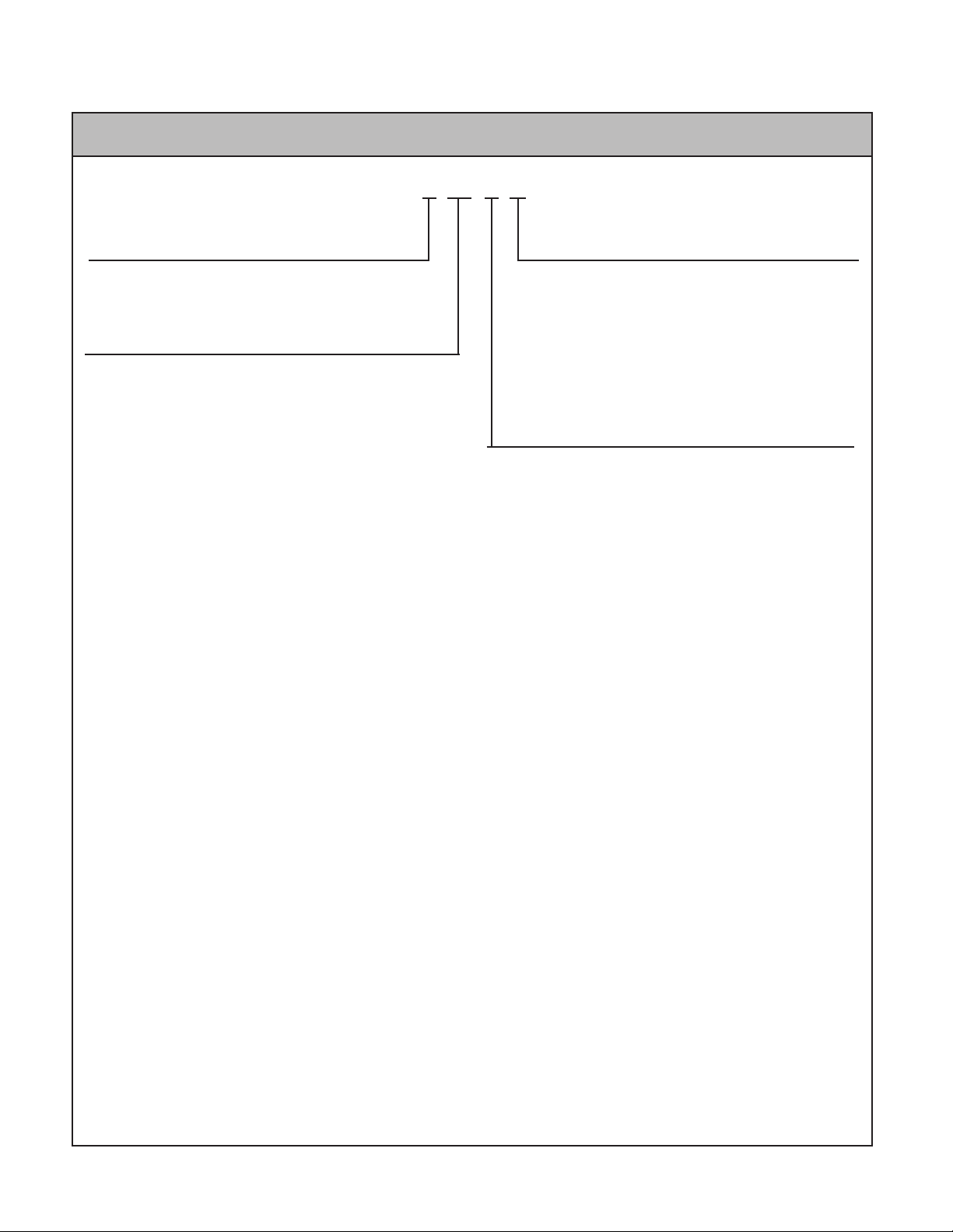
EVOLVER 303 APPLICATOR ASSEMBLY
A11976 - A B C
Head Conguration
0 = 60° Single Head
1 = 90° Single Head
2 = 60° Dual Head
3 = 90° Dual Head
Body Style
0 = For Highly Resistive Materials (Clear Coat)
1 = For Conductive Materials (Base/Clear)
2 = For Highly Conductive Materials (Base/Clear)
Atomization Technology
0 = Conventional Spray
1 = HVLP Spray
Ransburg
9
AA-07-03.2
Ransburg
Evolver 303 Robotic Atomizers - Introduction
EVOLVER 303 TUBING BUNDLE ASSEMBLY (ENGLISH)
A12000 - A BB C D
Tubing Bundle Length
0 = Air Tubing (Not Included)
1 = 15 Ft. Long Tubing Assembly
2 = 30 Ft. Long Tubing Assembly
Low Voltage Cable Length
00 = No Cable
01 = 25 Ft. Low Voltage, Non-Junction
02 = 40 Ft. Low Voltage, Non-Junction
03 = 50 Ft. Low Voltage, Non-Junction
04 = 75 Ft. Low Voltage, Non-Junction
05 = 100 Ft. Low Voltage, Non-Junction
06 = 15 Ft. Robot to JB / 15 Ft. JB to MicroPak
07 = 15 Ft. Robot to JB / 40 Ft. JB to MicroPak
08 = 15 Ft. Robot to JB / 60 Ft. JB to MicroPak
09 = 15 Ft. Robot to JB / 75 Ft. JB to MicroPak
10 = 25 Ft. Robot to JB / 25 Ft. JB to MicroPak
11 = 25 Ft. Robot to JB / 50 Ft. JB to MicroPak
12 = 25 Ft. Robot to JB / 75 Ft. JB to MicroPak
13 = 40 Ft. Robot to JB / 15 Ft. JB to MicroPak
14 = 40 Ft. Robot to JB / 25 Ft. JB to MicroPak
15 = 40 Ft. Robot to JB / 40 Ft. JB to MicroPak
16 = 40 Ft. Robot to JB / 60 Ft. JB to MicroPak
17 = 50 Ft. Robot to JB / 40 Ft. JB to MicroPak
31 = 25 Ft. Low Voltage, Non-Junction,
Evolver MicroPak
32 = 50 Ft. Low Voltage, Non-Junction,
Evolver MicroPak
33 = 75 Ft. Low Voltage, Non-Junction,
Evolver MicroPak
34 = 100 Ft. Low Voltage, Non-Junction,
Evolver MicroPak
35 = 15 Ft. Robot to JB / 15 Ft. JB to Evolver MicroPak
36 = 15 Ft. Robot to JB / 40 Ft. JB to Evolver MicroPak
37 = 15 Ft. Robot to JB / 60 Ft. JB to Evolver MicroPak
38 = 15 Ft. Robot to JB / 75 Ft. JB to Evolver MicroPak
39 = 25 Ft. Robot to JB / 25 Ft. JB to Evolver MicroPak
40 = 25 Ft. Robot to JB / 50 Ft. JB to Evolver MicroPak
41 = 25 Ft. Robot to JB / 75 Ft. JB to Evolver MicroPak
Robot Adapter
0 = Adapter (Not Included)
1 = Adapter (Fanuc)
2 = Adapter (ABB)
3 = Adapter (Fanuc-P200)
4 = Adapter (KAWASAKI-KE610L)
5 = Adapter (MOTOMAN-PX2850)
6 = Adapter (MOTOMAN-PX2900)
7 = Adapter (B & M LZ2000)
Fiber Optic Cable Length
0 = Fiber Optic Cable Not Included
1 = 15 Ft. Long Fiber Optic Cable
2 = 25 Ft. Long Fiber Optic Cable
3 = 50 Ft. Long Fiber Optic Cable
4 = 75 Ft. Long Fiber Optic Cable
5 = 100 Ft. Long Fiber Optic Cable
6 = 40 Ft. Long Fiber Optic Cable
AA-07-03.2
10
Evolver 303 Robotic Atomizers - Introduction
Ransburg
EVOLVER 303 TUBING BUNDLE ASSEMBLY (METRIC)
NOTES
A11061 - A BB C D
Tubing Bundle Length
0 = Air Tubing (Not Included)
1 = 4 /12m (15 Ft.) Long Tubing Assembly
2 = 9m (30 Ft.) Long Tubing Assembly
Low Voltage Cable Length
0 0 = No Cable
01 = 25 Ft. Low Voltage, Non-Junction
02 = 40 Ft. Low Voltage, Non-Junction
03 = 50 Ft. Low Voltage, Non-Junction
04 = 75 Ft. Low Voltage, Non-Junction
05 = 100 Ft. Low Voltage, Non-Junction
06 = 15 Ft. Robot to JB / 15 Ft. JB to MicroPak
07 = 15 Ft. Robot to JB / 40 Ft. JB to MicroPak
08 = 15 Ft. Robot to JB / 60 Ft. JB to MicroPak
09 = 15 Ft. Robot to JB / 75 Ft. JB to MicroPak
10 = 25 Ft. Robot to JB / 25 Ft. JB to MicroPak
11 = 25 Ft. Robot to JB / 50 Ft. JB to MicroPak
12 = 25 Ft. Robot to JB / 75 Ft. JB to MicroPak
13 = 40 Ft. Robot to JB / 15 Ft. JB to MicroPak
14 = 40 Ft. Robot to JB / 25 Ft. JB to MicroPak
15 = 40 Ft. Robot to JB / 40 Ft. JB to MicroPak
16 = 40 Ft. Robot to JB / 60 Ft. JB to MicroPak
17 = 50 Ft. Robot to JB / 40 Ft. JB to MicroPak
31 = 25 Ft. Low Voltage, Non-Junction,
Evolver MicroPak
32 = 50 Ft. Low Voltage, Non-Junction,
Evolver MicroPak
33 = 75 Ft. Low Voltage, Non-Junction,
Evolver MicroPak
34 = 100 Ft. Low Voltage, Non-Junction,
Evolver MicroPak
35 = 15 Ft. Robot to JB /
15 Ft. JB to Evolver MicroPak
36 = 15 Ft. Robot to JB /
40 Ft. JB to Evolver MicroPak
37 = 15 Ft. Robot to JB /
60 Ft. JB to Evolver MicroPak
38 = 15 Ft. Robot to JB /
75 Ft. JB to Evolver MicroPak
39 = 25 Ft. Robot to JB /
25 Ft. JB to Evolver MicroPak
40 = 25 Ft. Robot to JB /
50 Ft. JB to Evolver MicroPak
41 = 25 Ft. Robot to JB /
75 Ft. JB to Evolver MicroPak
Robot Adapter
0 = Adapter (Not Included)
1 = Adapter (Fanuc)
2 = Adapter (ABB)
3 = Adapter (Fanuc-P200)
4 = Adapter (KAWASAKI-KE610L)
5 = Adapter (MOTOMAN-PX2850)
6 = Adapter (MOTOMAN-PX2900)
7 = Adapter (B & M LZ2000)
Fiber Optic Cable Length
0 = Fiber Optic Cable Not Included
1 = 15 Ft. Long Fiber Optic Cable
2 = 25 Ft. Long Fiber Optic Cable
3 = 50 Ft. Long Fiber Optic Cable
4 = 75 Ft. Long Fiber Optic Cable
5 = 100 Ft. Long Fiber Optic Cable
6 = 40 Ft. Long Fiber Optic Cable
11
AA-07-03.2
Ransburg
SPRAY HEAD
ASSY.
MOUNTING
BLOCK ASSY.
Evolver 303 Robotic Atomizers - Introduction
SPRAY HEAD
ASSY.
MOUNTING
BLOCK ASSY.
VALVE MANIFOLD
ASSY.
SPRAY HEAD
MOUNTING
BLOCK ASSY.
VALVE MANIFOLD
A11976-3XX
90° DUAL HEAD
ASSY.
ASSY.
VALVE MANIFOLD
ASSY.
A11976-2XX
60° DUAL HEAD
SPRAY HEAD
ASSY.
MOUNTING
BLOCK ASSY.
VALVE MANIFOLD
ASSY.
AA-07-03.2
A11976-1XX
90° SINGLE HEAD
A12000-XXXXX REAR MANIFOLD TUBING ASSY. - ENGLIGH
A11061-XXXXX REAR MANIFOLD TUBING ASSY. - METRIC
A11976-0XX
60° SINGLE HEAD
Figure 1: Evolver 303 Solventborne Robotic Applicators
12
ROBOT MANIFOLD
QUICK DISCONNECT
ROBOT SPACER PLATE
ROBOT MANIFOLD QUICK
DISCONNECT RING
ROBOT SPACER PLATE
Evolver 303 Robotic Atomizers - Introduction
Ransburg
FEATURES
The features of the Evolver 303 Series Applicators
include:
!Quick disconnect spray head
!High quality Ransburg air cap and uid
nozzle
!Various adapter plates available to match
most robotic mounting congurations
! No external high voltage Cable. The intern-
ally mounted high voltage cascade requires
only low voltage control wiring
!Less waste to the spray booth with the dump
valve located internally next to the feed tube
!Assembly components made of durable
engineered resin material for optimum
mechanical strength and solvent resistance
!Small, light weight package allows for better
maneuverability in tight areas
!Negligible maintenance down time with the
quick disconnect feature. An atomizer can
be exchanged in less than two minutes for
off-line maintenance
!Field proven high voltage system
!Dual start, dual pitch air cap retaining ring
!Quick color change capability
!Clean interior design with slip-on shroud
!Internal fan and atomization air control valve,
with a mechanically timed trigger sequence
!Color coded air and trigger actuation lines
!Quick Change to a RMA-303 bell applicator
!Heavy duty design ensures excellent service
life even when subjected to the quick mo
tions
of robotic applicators
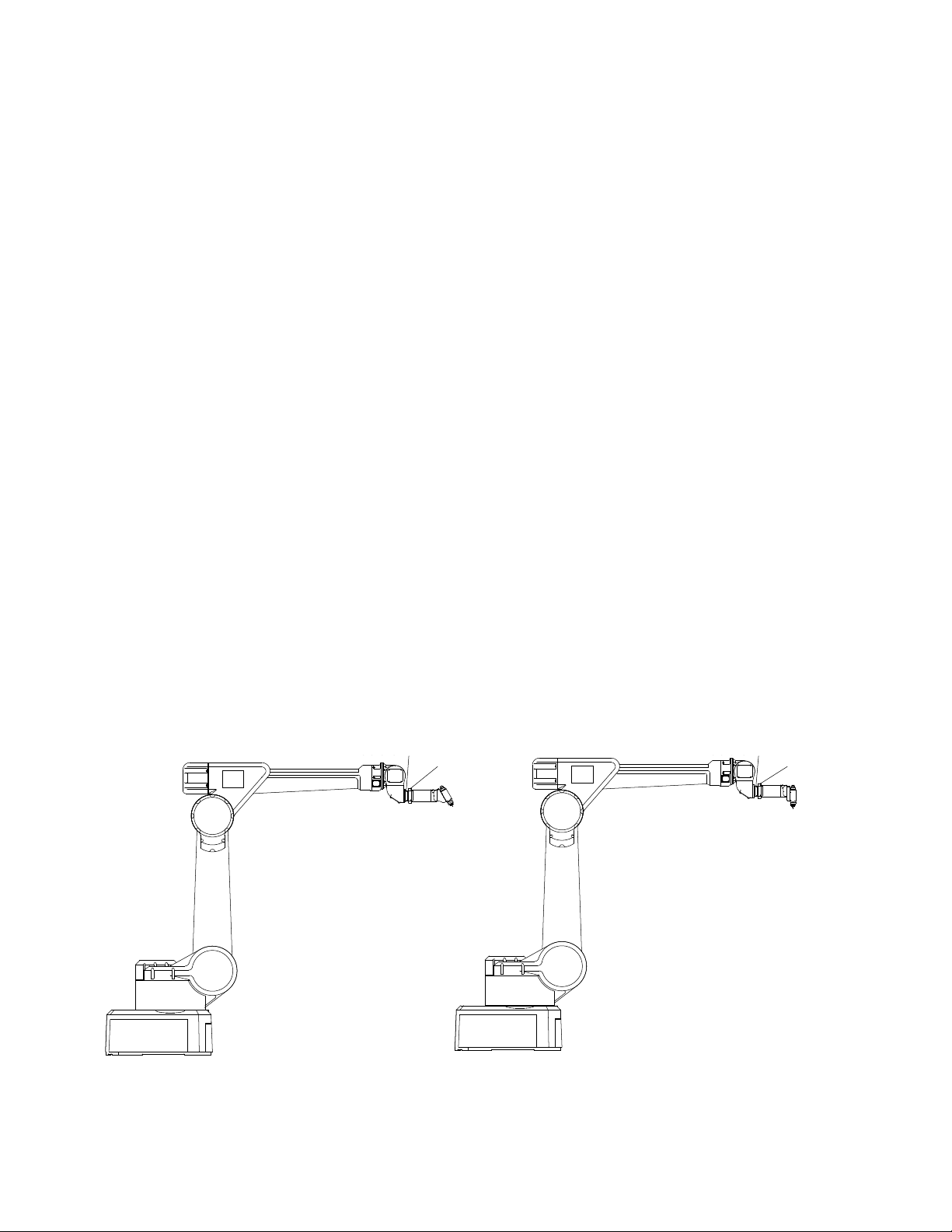
-0XX
A11976
60° SINGLE HEAD
MOUNTED ON ROBOT
RING
-1XX
A11976
90° SINGLE HEAD
MOUNTED ON ROBOT
13
Figure 2: Typical Robotic Applicator Mounting
AA-07-03.2
Ransburg
Evolver 303 Robotic Atomizers - Introduction
A11976-XXX EVOLVER
SPRAY APPLICATOR
ASSEMBLY
The spray applicator assembly is designed to connect to hollow wrist robots. A low voltage control
cable is supplied with the tubing bundle to connect
the cascade to the MicroPak power supply.
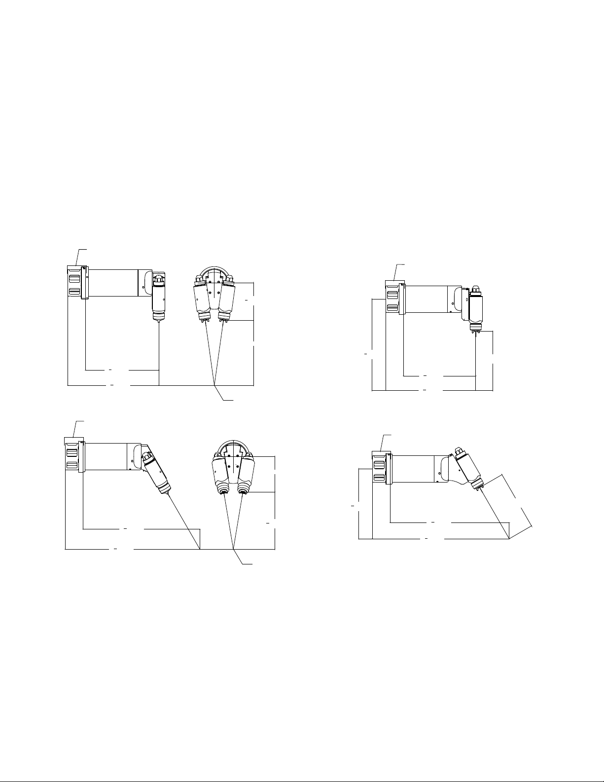
ROBOT ADAPTER AND
MOUNTING PLATE
3
6
[161.4]
8
11 [279.1]
3
12
[314.5]
8
3
15
[390.6]
8
CONVERGENCE POINT
ROBOT ADAPTER AND
MOUNTING PLATE
DUAL HEAD 90°
Tool Center-Point
Figure 3 shows the tool center-point information
for the four applicators. For dual head applicators,
the tool center-point is based upon the convergence point. For the single head applicators it
is based upon a 10" target distance. The "Tool
Center-Point Comparisons Table" compares the
tool center-point of several automatic spray applicators.
ROBOT ADAPTER AND
MOUNTING PLATE
1
[392.8]
15
2
1
12
[310.2]
4
1
15
[386.3]
4
SINGLE HEAD 90°
ROBOT ADAPTER AND
MOUNTING PLATE
10 [254.0]
TARGET DISTANCE
AA-07-03.2
22
19
3
[578.4]
4
3
[502.4]
4
DUAL HEAD 60°
6 [151.9]
3
11
[299.9]
4
5
9
[245.6]
8
CONVERGENCE POINT
Figure 3: Tool Center-Point
1
20
[511.4]
8
1
23
[587.5]
8
SINGLE HEAD 60°
10 [254.0]
TARGET DISTANCE
14

Evolver 303 Robotic Atomizers - Installation
INSTALLATION
Ransburg
EVOLVER 303 ROBOTIC
ATOMIZER
INSTALLATION
This information is intended ONLY to indicate the
general installation parameters of this product and,
where applicable, its working relationship to other
Ransburg system components in typical use. Each
installation is unique and should be directed by an
authorized Ransburg representative or conducted
from the Ransburg installation drawings provided
for your particular installation.
POWER SUPPLY
ASSEMBLY
Refer to the most current Power Supply Unit
manuals for complete information regarding power
supply installation.
• MicroPak Control Unit (LECU5004)
(for non-FM installations)
ELECTRICAL AND FIBER
OPTIC CONNECTIONS
The ber optic cable is included in the Evolver 303
tubing bundle, but not used. It is there, ready to
use, in case a user is using or chooses to use in
the future, a bell applicator, which requires the ber
optic cable. The ber optic connection is made on
the back of the applicator's robot plate. The ber
optic cable comes preassembled with connectors
that are secured in place by set screws tightened
from the side of the robot plate. An adequate
ground must be provided to the mounting plate to
ensure that uid ttings, etc. are at ground potential.
FLUID CONNECTIONS
The paint, solvent, and dump uid tubing are connected on the back of the robot plate with stainless
steel compression ttings and PFA tubing. Fluid
tubing requirements are shown in the "Signal
Identication Tables" in the "Installation" section.
• Stand-alone control/power supply unit
(A10406) (for FM installations)
• MicroPak Control Unit (LECU5004-31)
(for FM installations)
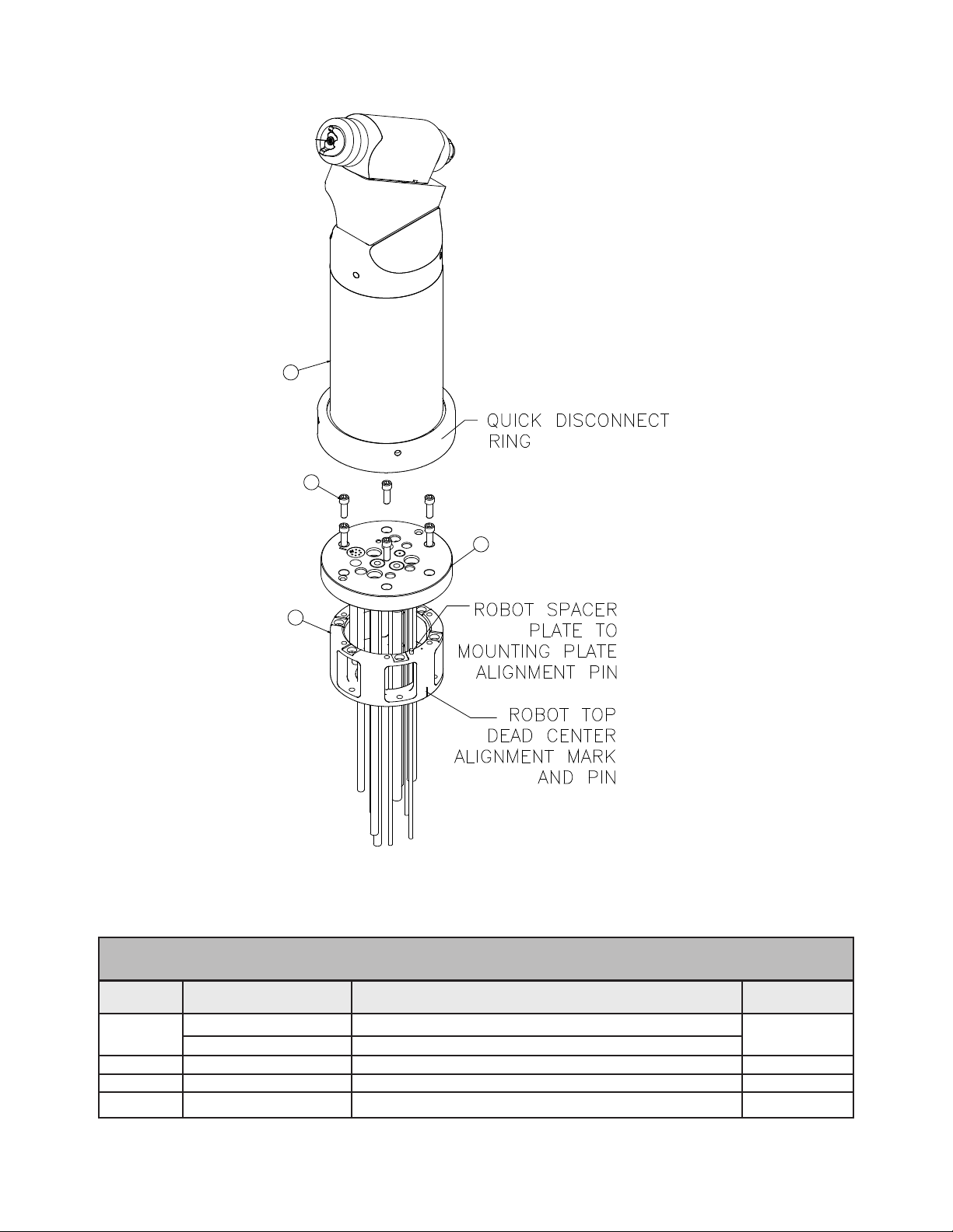
MOUNTING
The Evolver 303 is equipped with a quick disconnect assembly. The quick disconnect feature
consists of a robot plate which is permanently
attached to the robot through a wrist adapter plate
and a mating rear plate which is part of the Evolver
303 Spray Applicator assembly. The applicator
is secured to the robot plate with a threaded retaining ring.
15
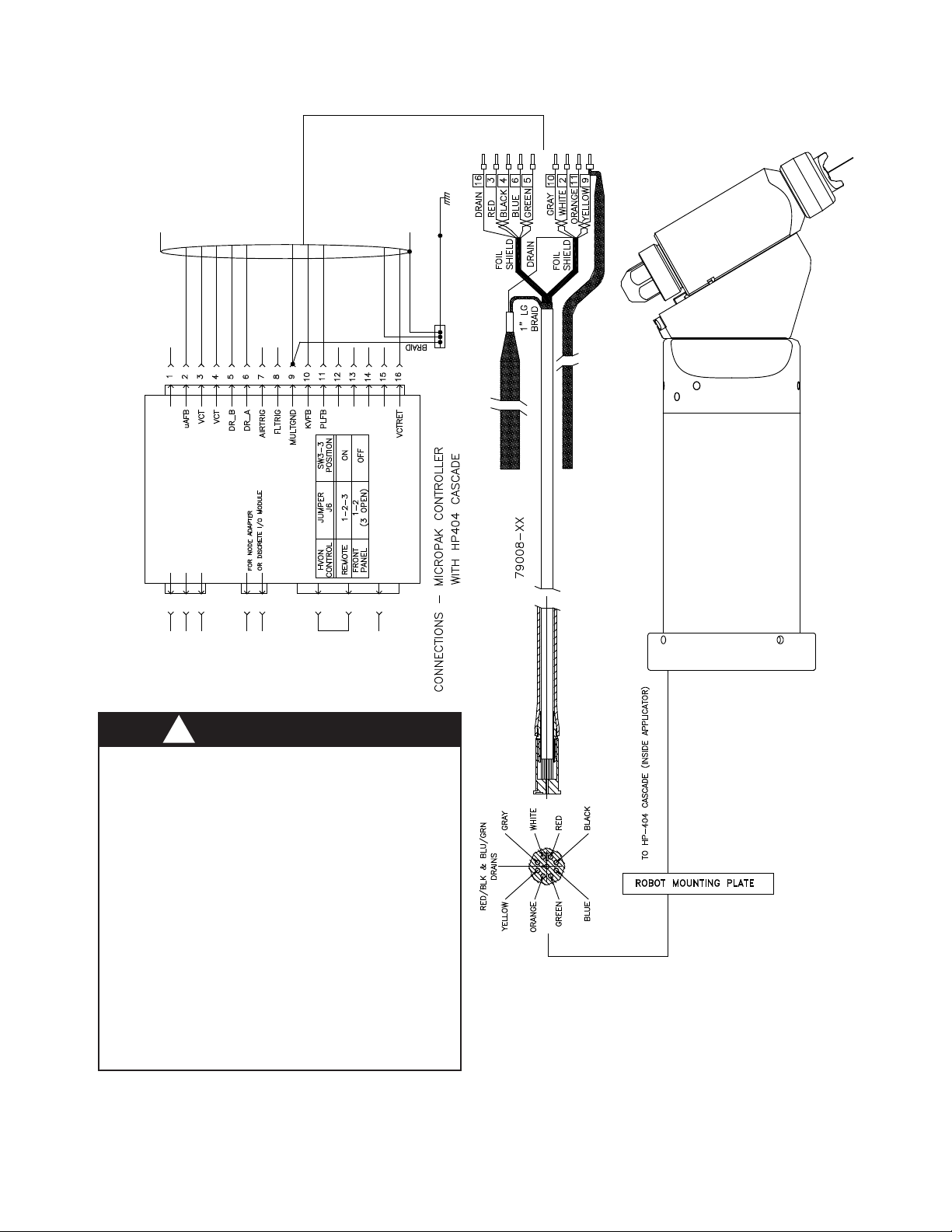
TYPICAL INSTALLATION
Figure 4 shows a typical installation of the Evolver
303 and the wiring installation of the applicator
with the MicroPak.
AA-07-03.2
HV GND. BUS
3
2
J6
1
J10
J2
+24 VDC
24 VRET
1
2
FACT. GND
+24 VDC
24 VRET 3
2
1
MICROPAK
BARE (DRAIN)
BARE (DRAIN)
YELLOW
ORANGE
N/C
N/C
N/C
N/C
GRAY
BLACK
N/C
N/C
GREEN
BLUE
N/C
J3
WHITE
RED
3/4" BRAID CABLE EARTH GROUND
Ransburg
Evolver 303 Robotic Atomizers - Installation
!
W A R N I N G
> The power supply MUST be located outside
the HAZARDOUS area (Reference OSHA,
NFPA-33, and your insurance company requirements.)
> User should be aware of, and adhere to,
all local re codes and ordinances.
> The user MUST provide a properly fused
disconnect between the power source and the
power supply which complies with appropriate
codes.
> Fluid supply must be grounded per NFPA-33.
AA-07-03.2
Figure 4: Low Voltage Cable Connections
16
Evolver 303 Robotic Atomizers - Installation
(IF USED)
TRIGGER SOLENOID
SUPPLIED BY OTHERS
DUMP
PAINT SUPPLY 1
Ransburg
IF A CAP CLEANER IS USED IT MUST BE
VENTED TO ATMOSPHERE WITHOUT PRESSURE
IF USING A CAP CLEANER THE
DIRECTLY INTO THE AIR CAP.
SOLVENT/AIR SHOULD NOT BE SPRAYED
BUILD UP.
AREA TO REDUCE ROTATION STRESS .
LEAVE TUBING SLACK IN THE WRIST AND ELBOW
SOLVENT SUPPLY
LUBRICATE THE TUBING BUNDLE
EXCESSIVELY TO EASE INSTALLATIO N
WITH THE ITW EQUIPMENT PURCHASE.
FOR REFERENCE ONLY AND IS NOT INCLUDED
THE ROBOT IS SHOWN
SOLVENT INBOUND
PAINT 1 INBOUND
AND EXTEND TUBING LIFE.
DUMP LINE OUT
(BLUE)
(ORANGE)
(GRAY)
(GREEN)
L.V. CABLE
(BLUE)
SEAL AIR/FAN AIR
SHAPING AIR/ATOMIZATION AIR
PAINT 1 TRIGGER VALVE SIGNAL
PAINT 1 DUMP VALVE TRIGGER SIGNAL
ANALOG SIGNAL AND
TRANSDUCER REQUIRED
(NATURAL)
(YELLOW)
(MAIN AIR IF EXTERNAL TR IGGER USED)
SOLVENT VALVE TRIGGER SIGNAL
BEARING AIR/PAINT TRIGGER
(USED FOR DUAL PURGE AND REGULATED AP PLICATIONS)
PAINT 2 TRIGGER/PEGULATOR P ILOT
CONTROLS BY OTHERS
CONTROL PANEL
17
INSIDE ENCLOSURE
ATTACH TO ISOLATED H.V. GND (FOR MICROPAK)
3/4" HV GND BRAID (DEARBORN #91234 OR EQUIVALANT)
120VAC
GROUND
ATTACH TO PANEL
AC NEUTRAL
BUILDING STEEL/GROUND ROD
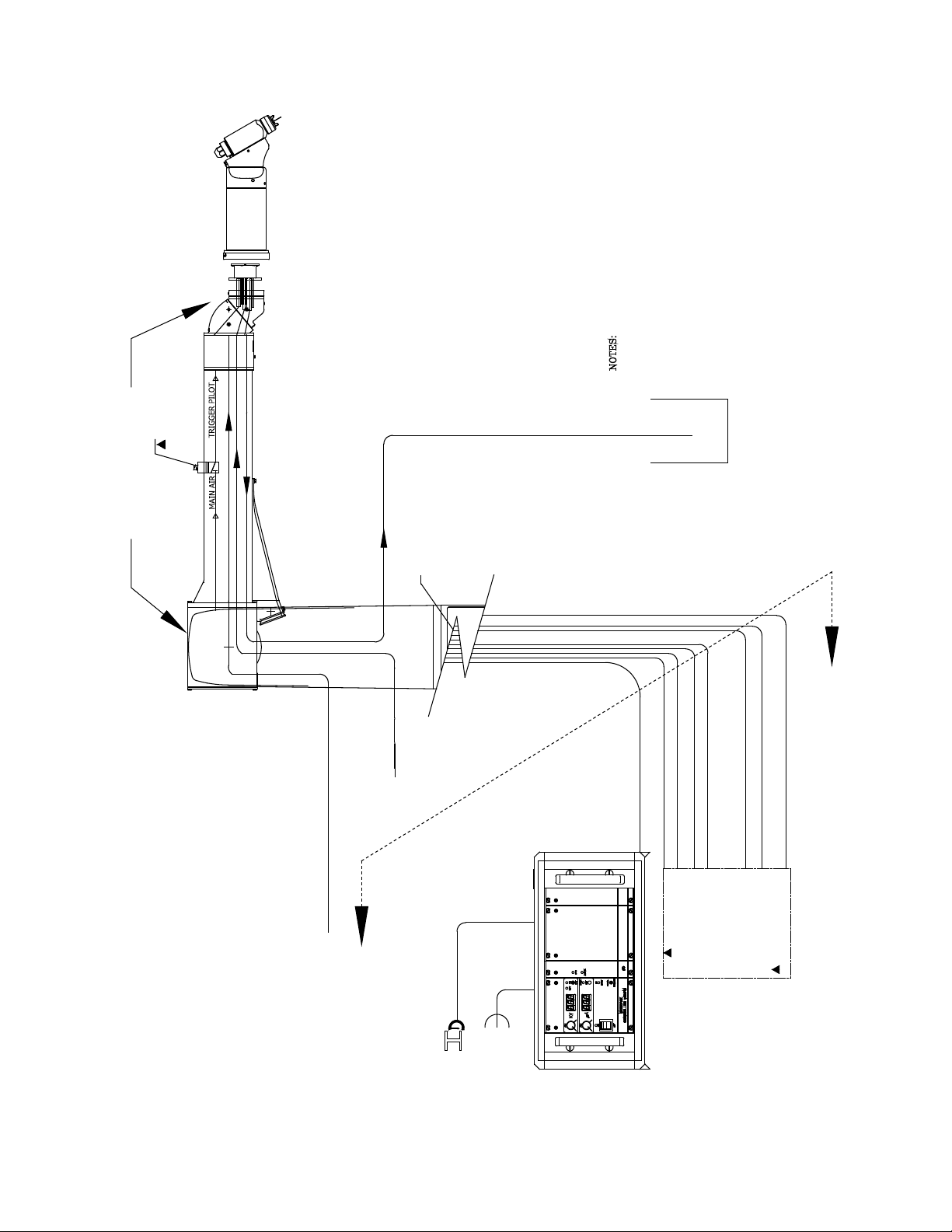
Figure 5: Evolver Spray Applicator Air And Fluid Layout
AA-07-03.2

Ransburg
Evolver 303 Robotic Atomizers - Installation
APPLICATOR AND
MANIFOLD ASSEMBLY
(See Figures 4, 5, and 6)
The tubing, hose, and low voltage cable come
bundled from the factory. Pull the bundle through
the robot spacer plate and robot wrist carefully
to prevent any cuts on the cable or hoses. Use
the six (6) socket head cap screws (76566-24C)
included with the rear manifold tubing assembly
to attach the rear manifold assembly (A12000 or
A11061) to the robot spacer plate (see Table 1).
Connect each signal line as required per "Signal
Identication Tables (English and Metric) Tubing
Bundles" in the "Installation" section.
Rear Plate Assembly
The rear plate assembly is designed to be at
ground potential when mounted to the robot plate
component within the tubing bundle assembly.
The air and uid ports are compactly oriented
for use in robotic applications. The interior air
supplies are ported through the ve (5) support
rods and also directly tubed to the upper manifold
assembly. On the exterior side of the rear plate,
the ports are provided with o-ring seals so that
the applicator can be quickly mated and secured
to the robot plate
Robot Plate
The robot plate is a component of the tubing bundle
assembly and intended to be permanently mounted
to the robot. A wrist adapter is also available, which
matches the robot's mounting conguration. The
incoming air lines, uid lines, low voltage cable,
and ber optic cable are connected to the ttings
provided on the back of the robot plate. The rear
plate of the applicator assembly is secured to the
robot plate with a threaded retaining ring.
screws fail and the applicator will break free. This
will leave the break-away ring and the mounting
ring attached to the robot.
Power Supply and Controls
The high voltage cascade located inside the Evolver 303 is controlled by the MicroPak control unit.
The low voltage ouput of the MicroPak is multiplied
by the internal cascade to the high voltage level
required. This eliminates the need for a high voltage cable. A low voltage cable interconnects the
cascade and the MicroPak control. The MicroPak
Eurocard format is designed to t in a conventional
19-inch or 1- inch rack and requires a 24V power
input at a maximum 3 amps. The MicroPak and
the internal cascade will produce voltages up to
100,000VDC.
The MicroPak is designed to electronically limit
current to provide safe operation in a spray booth.
The voltage and current draw of the applicator are
continuously displayed on the MicroPak control
panel. Voltage and over-current limits are adjust-able on the front of the MicroPak. MicroPak
internal safety circuits will shut down the system
on over-current and cable faults.
With additional control modules, all of the functions
of the Evolver 303 and MicroPak can be controlled
by a programmable controller. A Serial Digital
Module pneumatically controls the paint and
dump valves located on the applicator. An I/O
module provides communication between these
modules and the PLC.
The above modules are mounted in one 19-inch
rack and interconnected through a common
mother board.
Break-Away Feature (Optional)
The Evolver 303 can be converted to have a break-
away feature, by replacing the ve (5) stainless
steel screws with ve (5) special designed plastic
screws (77524-00). This feature is meant to reduce the damage to the applicator, robot, etc. If
a collision occurs, the ve (5) plastic break-away
AA-07-03.2
18
Evolver 303 Robotic Atomizers - Installation
Ransburg
Robot Spacer Plate
The robot spacer plate is included with the robot
manifold assembly to increase life of the tubing
bundle. The extra spacing it provides increases
the bend radius of the tubes and decreases the
hose or cable stress at the connector.
There is only one way the spacer plate may be
assembled to the mounting plate. The spacer
plate has an alignment pin that may only engage
in one hole position in the robot mount plate. This
provides the nal position to top dead center of
the robot.
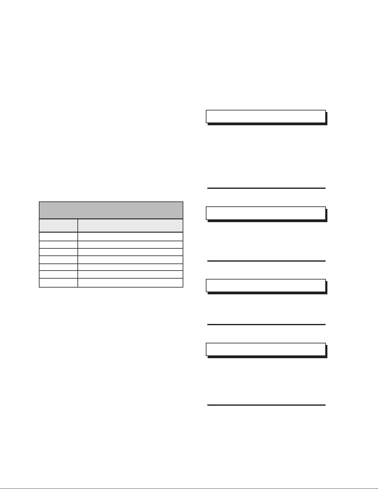
Six (6) robot spacer plates shown in Table 1 are
available for this product.
TABLE 1 - SPACER PLATES
Part # Description
79107-00 ABB Robots
78983-00 Fanuc P155, 145 Robots
79131-00 Fanuc P200 Robot
A10847-00 Adapter (Kawasaki-KE610L)
A10848-00 Adapter (Motoman-PX2850)
A10849-00 Adapter (Motoman-PX2900)
A10851-00 Adapter (B & M LZ 2000)
maintain FM Approval, this cable must be secured
to the stress relief bar on the rear of the power
supply. (See "A10406-XX Evolver MicroPak
Power Supply" manual for further information on
connecting the low voltage cable.)
NOTE
> With the exception of uid, dump, and
bearing air/paint trigger, all other pilot and
air supply lines should be bulkheaded
and their diameters increased one nom-
inal size. For example: atomization air
should be increased to a 1/2" ID (8mm)
from bulkhead plate to the volume booster.
NOTE
> If the length of the fan or atomization
air lines exceeds 30 ft. (10m), the lines
must be upsized to 1/2" ID (12mm for
metric).
NOTE
LOW VOLTAGE CABLE
INSTALLATIONS
For installations utilizing the LECU5004-XX MicroPak power supply, connect the low voltage cable
(79008-XX) from the robot manifold assembly to
the LECU5004-XX MicroPak controller or junction
box. If connecting to a junction box, use a junction
cable (77062-XX) to make the con-nection from
the junction box to the LECU5004-XX MicroPak.
Make connections as shown in Figure 4.
For installations utilizing the A10406-XX Evolver
MicroPak power supply, connect the low voltage
cable (A11353-XX or A11356-XX) from the robot
manifold assembly or junction box to the receptacle
on the rear of the A10406-XX power supply. To
19
> For the dipswitch settings for the
Evolver 303, reference the current MicroPak service manual.
NOTE
> Leave 12-24 inches (.30m-.61m) of
extra length on all lines to prevent extreme
tension being applied to these lines during
robot movement. This increases tubing
bundle life.
AA-07-03.2
Ransburg
Evolver 303 Robotic Atomizers - Installation
!
C A U T I O N
> Do not exceed 100' combined length of the
low voltage cables.
W A R N I N G
!
> If a non-explosion proof junction box/terminal
strip is used, it must be located outside the
hazardous area.
> Install and route the hoses and cable so
that they are NOT exposed to temperatures
in excess of 120° F. Ensure that all hose and
cable bends are NOT LESS THAN a 6-inch
(15cm) radius and are not subjected to more
than 360° of torsional twist. Failure to comply
with these parameters could cause equipment
malfunctions that might create HAZARDOUS
CONDITIONS!
W A R N I N G
!
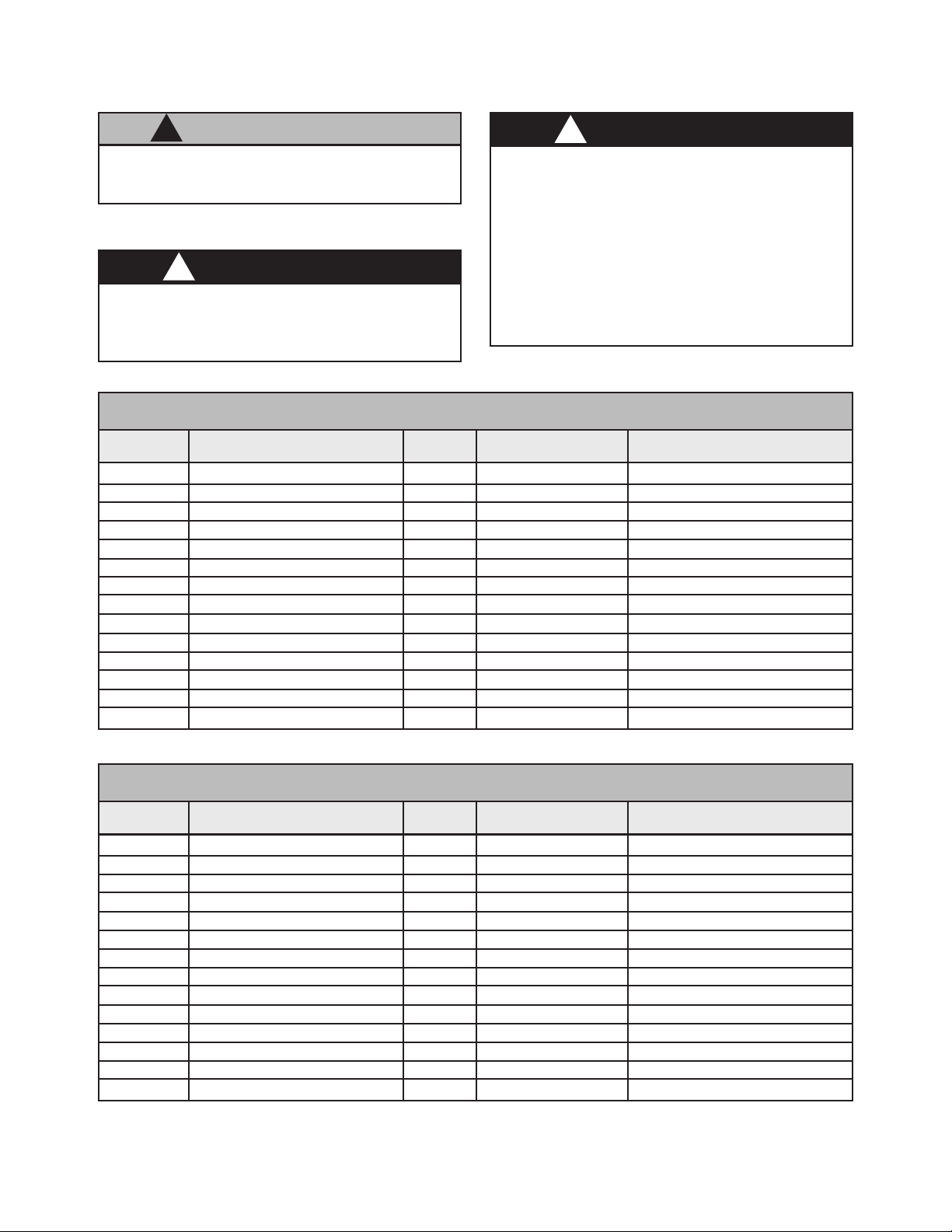
SIGNAL IDENTIFICATION TABLE (ENGLISH)
Abbr.
B.A/P.T Bearing Air (Paint Trigger) Yellow Nylon 1/4" OD X .170" ID
B.A RTN Bearing Air Return Yellow Nylon 5/32" OD X .106" ID
BRK Brake Air Orange Nylon 1/4" OD X .170" ID
DL Dump Line Natural PTFE 5/16" OD X .250" ID
F.O Fiber Optic Cable Natural Polyethylene 1/4" OD (jacket)
LV Low Voltage Cable Black N/A N/A
P Paint In Natural PTFE 3/8" OD X .250" ID
PT Paint Trigger Green Nylon 5/32" OD X .106" ID
DT Dump Trigger Silver Nylon 5/32" OD X .106" ID
SA.I/A.A Inner Shaping Air (Atom, Air) Blue Nylon 5/16" OD X .250" ID
SOL Solvent In Natural Nylon 1/4" OD X .170" ID
SA.O/F.A Outer Shaping (Fan Air) Gray Nylon 5/16" OD X .250" ID
ST/RP Solvent Trigger Signal Blue Nylon 5/32" OD X .106" ID
T.A Turbine Air Green Nylon 3/8" OD X .275" ID
Description Color
Tubing Material
Tubing Size
AA-07-03.2
SIGNAL IDENTIFICATION TABLE (METRIC)
Abbr.
B.A/P.T Bearing Air (Paint Trigger) Yellow Nylon 6mm OD X 4mm ID
B.A RTN Bearing Air Return Yellow Nylon 4mm OD X 2.7mm ID
BRK Brake Air Orange Nylon 6mm OD X 4mm ID
DL Dump Line Natural PTFE 10mm OD X 8mm ID
F.O Fiber Optic Cable Natural Polyethylene 1/4" OD (jacket)
LV Low Voltage Cable Black N/A N/A
P Paint In Natural PTFE 8mm OD X 6mm ID
PT Paint Trigger Green Nylon 4mm OD X 2.7mm ID
DT Dump Trigger Silver Nylon 4mm OD X 2.7mm ID
SA.I/A.A Inner Shaping Air (Atom, Air) Blue Nylon 8mm OD X 6mm ID
SOL Solvent In Natural PTFE 6mm OD X 4mm ID
SA.O/F.A Outer Shaping (Fan Air) Gray Nylon 8mm OD X 6mm ID
ST/RP Solvent Trigger Signal Blue Nylon 4mm OD X 2.7mm ID
T.A Turbine Air Green Nylon 10mm OD X 8mm ID
Description Color
Tubing Material
Tubing Size
20
Evolver 303 Robotic Atomizers - Installation
2
3
Ransburg
1
4
Figure 6: Applicator and Manifold Assembly
APPLICATOR AND MANIFOLD ASSEMBLY - PARTS LIST (Figure 6)
Item #
Part # Description Qty
1 A11061-XXXXXXX Tubing Bundle Assembly (Metric) 1
A12000-XXXXXXX Tubing Bundle Assembly (English)
2 A11976-XXX Evolver 303 Spray Applicator Assembly 1
3 76566-24C Screw, 1/4-20 X 3/4" Lg., SHCS 6
4 See Table 1 Robot Adapter 1
21
AA-07-03.2
Ransburg
Evolver 303 Robotic Atomizers - Installation
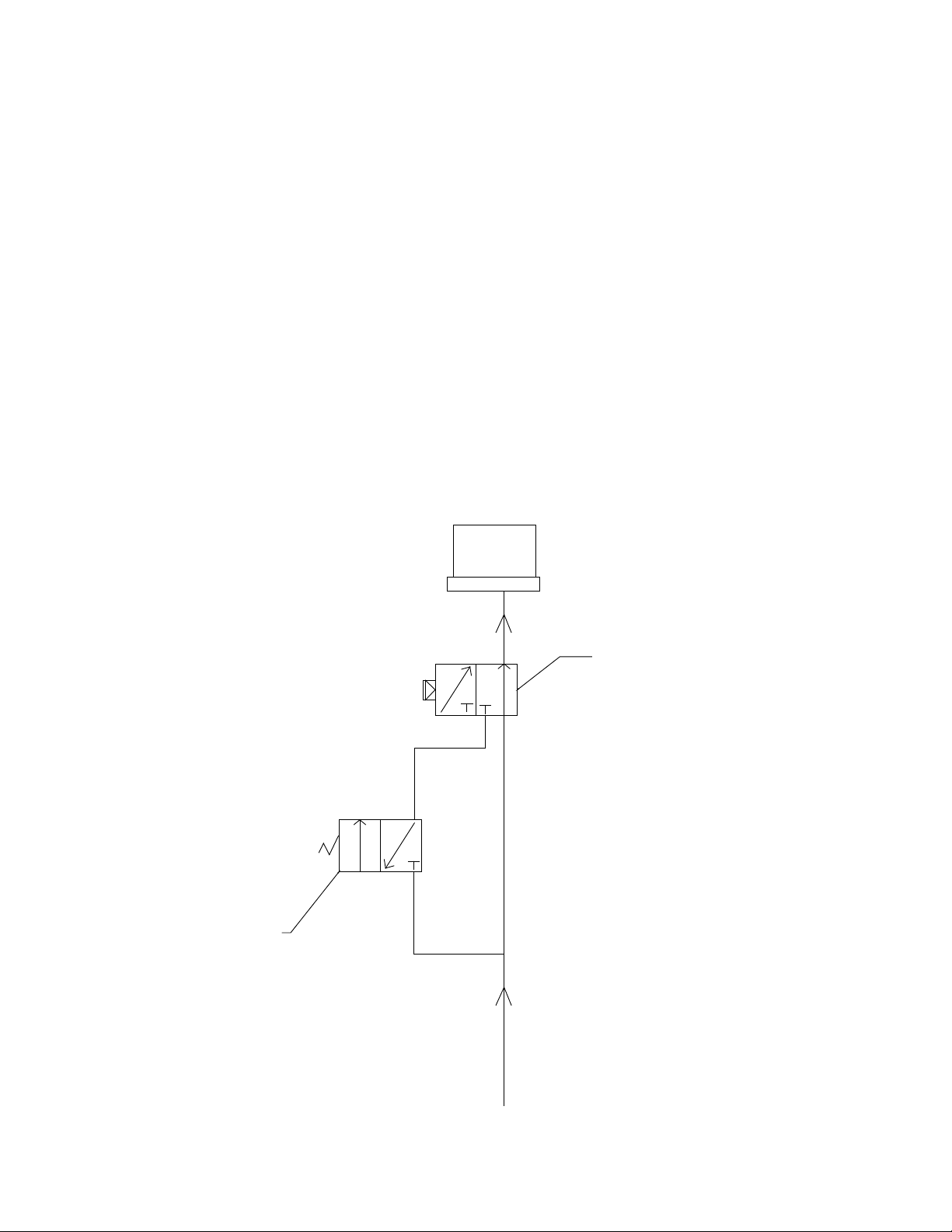
SPRAY / BELL
APPLICATOR
TRIGGERING
If you are currently using an RMA-303 bell applicator system and want to add the Evolver 303
spray applicator system to spray using the same
tubing bundle, a simple conversion must be made
in order to allow for switching between spray and
bell applicators. Figure 7 shows the recommended system that should be placed in the bearing
air line between the main air input and the robot
manifold plate. It is suggested that this circuit
be placed on the robot arm. This system should
also be used when the user is implementing the
Evolver 303 spray applicator system and plans to
use RMA-303 bell applicators as well.
In Figure 7, the trigger solenoid must be an electronically activated, normally closed valve with
exhaust, or a 3-way valve, with 100 psi max.,
24VDC. Typically this solenoid already exists in
the robot arm and can be used in this circuit. The
spray applicator trigger/bearing air select valve
must be a pneumatically activated, normally open
solenoid. A suggested solenoid is P/N 11678-01.
An additional solenoid must be used to activate the
PT (Paint Trigger) valve. If any of these solenoids
are located inside a hazardous area, they must
be explosion proof.
SPRAY APPLICATOR SIDE
TRIGGER
SOLENOID
BEARING AIR LINE
SPRAY APPLICATOR TRIGGER/
BEARING AIR SELECT
BELL APPLICATOR SIDE
MAIN AIR LINE
AA-07-03.2
Figure 7: Conversion Schematic
22
Evolver 303 Robotic Atomizers - Installation
Ransburg
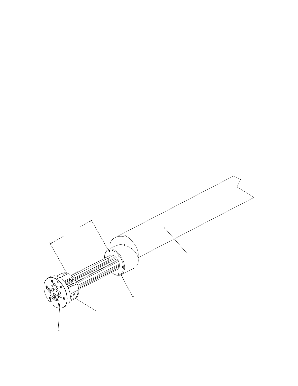
TUBING BUNDLE
INSTALLATION
Typically, the tubing bundle is pulled through the
robot arm from the robot wrist side. Keep the
bundle taped except for the portion of the bundle
that will be inside the arm. Pull the tubing through
the wrist and arm, leaving about 250mm (10") of
tubing sticking out of the front of the wrist plate
(see Figure 8).
Fasten the cable bundle in the robot at the rear
exit of the arm. Push the robot spacer plate and
applicator mounting plate to the robot wrist plate
aligning the top dead center marks of the spacer
plate and robot wrist plate. Fasten using appropriate screws. Installing the tubing bundle in this
fashion will increase tubing bundle life signicantly.
BUNDLE LUBRICATION
When the tubing bundle is installed, it should be
lubricated with a generous amount of lubricant to
increase the service life of the tubes. A recommended lubricant is Shell Alvania EP #02. There
are other lubricants that are available for use.
Prior to using a lubricant, ensure it is silicone free,
resists heat breakdown, and is compatible with
the materials being applied.
23
250 MM
(10")
APPROX.
TYPICAL
ROBOT
ARM
ROBOT WRIST PLATE
ROBOT
SPACER
PLATE
APPLICATOR
MOUNTING
PLATE
Figure 8: Tubing Bundle Installation
AA-07-03.2

Ransburg
Evolver 303 Robotic Atomizers - Installation
If you currently have an A12000 or A11061 Tubing
Bundle for either a RMA-303 or an Evolver 303
and the number engraved on your tubing bundle
plate is A11062-REV.A through A11062-REV.G,
this plate will not allow you to switch between
RMA-303 applicators and Evolver 303 applicators.
If you have Rev. H or greater, the online switching
capability is provided in the plate.
If you desire to switch between RMA-303 and
Evolver 303 applicators, you must contact your
local authorized Ransburg distributor for the plate
to be reworked. Once the rework is complete, the
plate can be re-installed just as before, and both
applicator types used interchangeably.
NOTES
AA-07-03.2
24

Evolver 303 Robotic Atomizers - Operation
OPERATION
Ransburg
W A R N I N G
!
> Operators must be fully trained in safe
operation of electrostatic equipment. Operators must read all instructions and safety
precautions prior to using this equipment
(see NFPA-33).
As with any spray nishing system, operation
of the Evolver 303 involves properly setting the
operating parameters to obtain the best nish
quality for the coating material being sprayed,
while maintaining correct operation and reliability
of the equipment used. Adjustments to operating
parameters, which cover spraying, cleaning, and
on/off control, include the following:
• Coating Materials
• Fluid Flow Rate Control
• Fluid Valve / Trigger Control
• Atomization Air (Paint Atomization
Control)
• Fan Air (Pattern Control)
• Electrostatic Voltage
• Target Distance
SPRAY APPLICATOR
CONTROLS
Atomization Air (SAI/AA) /
Fan Air (SAO/F.A)
The atomization and fan air are turned on by the
trigger line and are controlled by an internal air
valve located in the applicator head. During normal
operation with applicator triggered off, there is a
slight bleed of air through the atomization port.
Atomizing Air
Adjustments are made through the robot PLC or
a manually adjustable air regulator. The lowest
air pressure required to break up the paint should
be used. Lower atomizing air pressures result in
less overspray and increased transfer efciency.
Fan Air
Adjusting the fan air increases or decreases the
size of the spray pattern. Increasing pressure
increases pattern size. Pattern adjustment should
be made to suit the size and shape of the object
being painted. This adjustment is made through the
robot PLC or a manually adjustable air regulator.
25
W A R N I N G
!
> Electrical discharge of a high electrical
capacitance uid/paint system can cause re
or explosion with some materials. If arcing
occurs when a specic coating material is
used, turn the system off and verify that the
uid is non-ammable. In these conditions,
the system is capable of releasing sufcient
electrical and thermal energy to cause igni-
tion of specic hazardous materials in the air.
Air cap atomization and fan pressures should be
set and recorded using an air cap test kit. This
provides a consistent measurement, so initial
settings may be duplicated at any time. (See
"Accessories" in the "Parts Identication" section.)
HVLP SPRAY
The Evolver 303 HVLP models, when properly
set-up, are designed to provide maximum transfer efciency by limiting air cap pressures to 10
psi (0.7 bar) (in the U.S., this complies with rules
issued by SCAQMD and other air quality authorities). Air cap pressures should be measured with
an optional air cap test kit. (See "Accessories" in
the "Parts Identication" section.)
AA-07-03.2

Ransburg
Evolver 303 Robotic Atomizers - Operation
NOTE
> For HVLP operation (max. 10 psi, 0.7
bar cap pressure), DO NOT exceed the
air inlet pressure, which was read at the
gun base before the tubing manifolds,
given as follows:
PSI (Bar) CAP #
42 (2.9) 48-1
42 (2.9) 481-1
FLUID VALVE CONTROLS
Trigger and Dump
(See Figure 9)
The uid valves in the Evolver 303 are actuated
by an air signal. The air pressure must exceed
70 psi (4.8 bar) to assure proper actuation of the
valve. Applying air to the valve actuator turns on
the uid ow for the valve.
The paint trigger valve controls the paint ow
to the applicator. When actuated, paint ows
through the valve to the coiled uid tube and into
the spray head.
The dump valve controls the paint ow through the
dump line. When actuated, paint ow is directed
to the dump return line. This provides a method
of rapidly removing paint from the incoming line
for cleaning and/or color change. Normally, the
dump valve is not actuated at the same time as
the paint valve since the paint valve is intended
to cause the uid to ow to the applicator head
at the prescribed input pressure.
SINGLE PURGE
SPRAYING
When the target part is nished and a color change
is desired, ensure voltage is turned off.
W A R N I N G
!
> Failure to turn voltage OFF during color
change sequence when solvent is owing
through the uid nozzle, could cause a re
or explosion.
When the cleaning cycle with solvent is complete,
an air purge for several seconds is recommended
to clean and dry the ID of the dump line hose.
Paint Viscosity
The applicator is capable of atomizing paint of
most any desired viscosity. It is recommended
to keep the material viscosity as low as possible.
This allows spraying at lower fan and atomization
air pressures which result in less overspray and
higher transfer efciency.
W A R N I N G
!
> Most paints and solvents, including those
listed in "Polar & Non-Polar Solvents Chart"
in the "Maintenance" section, are toxic to a
certain degree and ammable or combustible.
Use them only in a well ventilated atmosphere.
Use protective equipment as required in the
Material Safety Data Sheet supplied with the
substance.
Fluid Flow Rate
Fluid ow is adjusted through the robot PLC by
varying the pilot pressure to an exterior uid regu-
lator. Fluid pressures from the circulating system
may exceed the maximum uid pressure rating
of the Evolver 303 applicator. Because of these
high uid pressures, a manual step-down uid
regulator must be used.
Applicator Trigger Control Air
The Evolver applicators require a minimum of 70
psig trigger control air pressure to ensure proper
operation of the applicator piston.
AA-07-03.2
26

Evolver 303 Robotic Atomizers - Operation
Ransburg
Electrostatic Voltage
Under no load conditions, the maximum voltage
limit for these spray applicatorss is 100 kV. Some
painting operations may require different voltage
settings to obtain optimum transfer efciencies. If
Faraday cage areas are predominant on the item
being painted, a lower voltage setting would aid
in coating these areas.
NOTE
> If a 0 kV command is sent to the Mi-
croPak, a feedback fault will occur.
When not spraying, it is recommended to set back
voltage to 30-40 kV or off between target parts.
Sometimes, depending upon target carrier spacing, higher setback voltages may be required. The
ramp-up time for the HP-404 cascade (0-100 kV)
is approximately 3 seconds.
W A R N I N G
!
> If a bell applicator is being used, and
needs to be switched to a spray applicator,
the bell applicator must have all voltage,
uids, and air turned off, and the bell cup
completely spun-down before the changeout can occur.
The MicroPak voltage ramp-down works at a rate
of 33 kV/sec.
Target Distance
The distance between the applicator tip and the
article being painted should be 10-14 inches
(.25m-.36m) for a single head applicator and at
or near the convergence point for a dual head
applicator. Excessive distance causes a waste
of coating material and wrap back (paint particles
being deposited on the applicator body or the robot
arm). At close distances the voltage at the tip of
the applicator will be reduced, which decreases
the charging effect of the applicator.
W A R N I N G
!
> If target distance is less than 8-inches
(.20m), an arc could occur.
Applicator Head
Fluid Tube to
Dump Valve
To Paint Waste Tank
Paint Valve
Solvent In
Cup Wash
Solvent Valve (Plugged)
Paint Supply
27
Figure 9: Single Purge Air and Fluid Passage
Schematic
AA-07-03.2

Ransburg
MAINTENANCE
Evolver 303 Robotic Atomizers - Maintenance
Good maintenance is essential to safe and productive operation. Schedules should be established
by the user, based on the following general information and observations of the initial production
requirements. The Ransburg maintenance and
safety information should be made available to
each operator.
Normal re protection measures are necessary,
including proper storage of paints and solvents
and the proper disposal of waste. Ready access
to appropriate re extinguishing equipment is
required. For details, consult the appropriate
NFPA safety information and/or applicable country
safety standard.
W A R N I N G
!
> An electrical discharge or spark may create
an electrical and/or re hazard during maintenance. Do not clean or service the spray
applicator with the power supply on. Verify
that the power supply has been locked out and
tagged out per OSHA and/or your applicable
country safety codes.
> Unexpected robot movement can be haz-
ardous. Do not adjust or repair the spray applicator when the robot is operating or waiting
to start. The robot must be locked out and
tagged out per OSHA and/or your applicable
country safety codes.
ROUTINE MAINTENANCE
SCHEDULE
Follow these maintenance steps to extend the
life of the spray applicator and ensure efcient
operation:
Several Times Daily
1. Turn the MicroPak control unit OFF! Follow
"Lockout/Tagout Procedures".
2. Inspect the uid nozzle, air cap, and elec-
trode wire for paint accumulation. Clean as frequently as necessary. See "Procedures" in the
"Maintenance" section.
W A R N I N G
!
> Take precautions to see that skin is not
punctured by sharp electrode.
C A U T I O N
!
> Do not bend the applicator electrode while
wiping. Never immerse the applicator in solvents. This will cause damage to the electrical
components.
Daily (Or at Shift Start)
1. Turn the MicroPak control unit OFF and:
AA-07-03.2
> Solvents used for equipment ushing must
have ash point ratings equal to or greater than
the ash point rating of the coating material.
Solvents used for general cleaning must have
ash point ratings higher than 100°F (37.8°C).
>Never remove spray applicator head from
assembly while under pressure.
•
Check within 20 ft. (6.1 meters) of the point
operation (of the applicator) and remove or
ground ALL loose or ungrounded containers.
• Inspect workholders for accumulated coating
materials (remove such accumulations if
present). Ensure resistance to ground from
work holder is less than 1 megohm.
• Check that the nozzle assembly is clean and
undamaged. Ensure air caps are clean and
undamaged.
of
28

Evolver 303 Robotic Atomizers - Maintenance
Ransburg
2. Turn the MicroPak control unit ON! Energize
high voltage.
Shut-Down (Or at Shift End)
1. Turn the MicroPak control unit OFF.
2. Flush the lines and allow the solvent to remain
in the lines. See "Procedures" in the "Maintenance" section.
3. Wipe the applicator (including the air cap)
and robot wrist with a cloth and a suitable, clean
non-polar solvent.
Weekly
1. Check the entire system for damage, leaks,
and paint accumulation.
2. Clean the atomizer assembly.
3. Conduct a current output test. See "Procedures" in the "Maintenance" section.
C A U T I O N
!
> Failure to use a non-polar solvent may
cause a decrease in voltage at the tip of the
applicator. This will signicantly decrease
transfer efciency.
4. Remove end cap [1]. Removing the end cap
releases tension on all internal spray head components. Remove needle spring [2] and valve spring
[3], which are loose after removing the end cap.
C A U T I O N
!
> Never attempt to clean the air cap holes
with a wire or other metal object. Doing so
may damage the air cap, resulting in distortion of the spray pattern.
PROCEDURES
Applicator Cleaning/Service
(See Figure 10a and 10b)
1. Flush the paint supply line and the applicator
paint passages using a solvent which is compatible
with the material being sprayed. Continue to ush
until all traces of paint are gone.
2. Turn off the solvent supply, actuate paint pushout air at color changer, and trigger the applicator
and PT. Allow all of the uid to drain from the
spray applicator uid passages.
3. Clean the exterior surfaces of the spray appli-
cator with a solvent soaked rag. As long as the
applicator is intact, a polar solvent may be used
for all cleaning, however, after cleaning, wipe off
all surfaces with a non-polar solvent to reduce
conductive residue on the applicator's surface.
(See "Polar & Non-Polar Solvents Chart" in the
"Maintenance" section regarding proper solvent
selection.)
5. Remove the air cap retainer [36] and air cap
[35]. Soak in a non-polar solvent if necessary. If
paint remains in the air cap holes, clean with a
toothpick or similar soft wood object. Air caps are
best cleaned in an ultrasonic cleaner.
6. Remove the air cap locator [33] and uid tip
[34]. Clean using a non-polar solvent.
7. Tightly grip the plastic needle [6] and unscrew
counter-clockwise to remove the front electrode
needle assembly. A short piece of H-2339 tub-
ing (1/4" OD x 0.175" ID) pressed over the front
needle will assist in unscrewing the assembly.
If required, use needle nose pliers with masking
tape or duct tape. Carefully clean with a non-polar
solvent. Replace any parts that show signs of
wear or damage.
C A U T I O N
!
> If using needle nose pliers to unscrew the
front needle, be very careful. Do not grip on
the tapered sealing surface. If the pliers slip,
they could damage the tapered sealing surface
of the needle.
29
AA-07-03.2

Ransburg
POLAR AND NON-POLAR SOLVENTS
Evolver 303 Robotic Atomizers - Maintenance
Non-Conductive (Non-Polar)
Amyl Acetate
Methyl Amyl Acetate
Toluene
Xylene
High Flash Naptha
Mineral Spirits
8. Remove uid nozzle [32] by unscrewing
counter-clockwise. Inspect o-ring [30] and all passages for build up or damage. Clean or replace
as necessary. Lubricate and reinsert o-ring into
applicator barrel and reinstall uid nozzle. Torque
uid nozzle to 25 lbs•in (2.82 Nm).
Moderately Conductive
Methyl Isobutyl Ketone
Ethyl Acetate
Methyl Ethyl Ketone
Butyl Carbitol
NOTE
> There should be a small gap between
the uid nozzle and the applicator barrel
after tightening.
Extremely Conductive (Polar)
Methanol
Carbitol
Diacetone
Butyl Alcohol
Acetone
Butyl Cellosolve
10. Screw uid tip [34] back into place. Hand
tighten rst, then with a small wrench, tighten an
additional 30 degrees.
11. Replace air cap locator [33], air cap [35], and
air cap retainer [36].
12. Apply a thin lm of petroleum jelly to valve and
needle springs [2] and [3]. Install the springs
back into the end cap and the spray head
assembly.
13. Screw end cap [1] back on.
9. After cleaning, insert the electrode assembly
[31] back into the spray head assembly. Apply
Adhesive #222, low strength (purple) thread-locker,
to the threads of the electrode assembly before
reassembly.
NOTE
> The uid tip [34] should always be
installed and tightened before installing
the needle and valve springs.
C A U T I O N
!
> After tightening the uid tip, always check
to see if the proper gap (1/16") between the
needle nuts and air valve stem occur, before
installng the needle and valve springs back
into the head.
Current Output Test
1. Clean and blow out all uid passages with
non-conductive solvent.
2. Remove from robot and perform bench test
using a spare tubing bundle.
3. Turn the control unit power ON.
4. Activate high voltage and slowly approach the
applicator electrode with ground hook or wire.
5. Monitor the current output on MicroPak. Current should rise as ground approaches. At ap-
proximately 85 microamperes, the MicroPak will
shut off. The OVERCURRENT indicator should
come on.
The spray head can be removed from assembly
as shown in Figure 10a for cleaning and service.
AA-07-03.2
30

Evolver 303 Robotic Atomizers - Maintenance
ROTATE HEAD APPROX.
45° CCW TO REMOVE
Ransburg
3
INSERT A
THROUGH THE HOLE TO LOOSEN
THE LOCKING SCREW (3), TURN
THE SCREW CLOCKWISE, WHICH IN
TURN WILL DISENGAGE THE
LOCKING TAB (2), TURN UNTIL THE
TAB COMES IN CONTACT WITH THE
INSIDE WALL. AS ILLUSTRATED IN
FIGS. 24 THRU 27.
THEN ROTATE THE HEAD AS
SHOWN BY HAND AND PULL UP TO
REMOVE.
" ALLEN WRENCH
16
35
31
34
36
33
32
30
Figure 10a: Spray Head Removal
27
28
29
1/16" (1.59 MM)
1
3
6
4
2
5
31
Figure 10b: Spray Head Assembly
AA-07-03.2

Ransburg
SPRAY HEAD ASSEMBLY - PARTS LIST (Figure 10b)
Evolver 303 Robotic Atomizers - Maintenance
Item #
1 79148-00 End Cap, Spray Head 1
2 17615-00 Spring, Compression 1
3 9334-00 Spring, Valve Return 1
4 7733-07 Jam Nut 1
5 76199-00 Rear Adjusting Nut 1
6 79151-00 Assembly, Needle Shaft 1
27 RME-38 Return Spring, Piston 1
28 EMF-7 Seal, Washer 1
29 RME-32 Seal 1
30 79001-01 O-Ring, Solvent Proof 1
31 70430-01 Electrode, High Wear 1
32 EMF-195 Nozzle, Fluid Hole 1
33 EMF-192 Locator, Air Cap 1
34 79140-02 Fluid Tip, .055" (1.4mm) Diameter 1
35 79153-65R-1 Air Cap, Pined 1
36 79154-00 Retaining Ring, Tapered 1
Part # Description Qty
NOTE
> Ensure that the fan and atomization air
are on and owing prior to triggering the
uid. Ensure air before uid adjustment
is correct. Failure to follow this sequence
will cause spits and defects on the part
being painted.
AA-07-03.2
32

Evolver 303 Robotic Atomizers - Maintenance
Ransburg
SERVICE
Because we want to provide our users with the
most up-to-date technology possible, we are constantly seeking to improve products. If a change
in product conguration occurs after it is on the
market, we will implement that technology in future
production and, if practical, make it available to
current users. The following service information is
based on standard specications and procedures
for this product. If you nd some minor deviations
between this information and your equipment
because of design or manufacturing changes,
contact your Ransburg representative to resolve
the difference.
W A R N I N G
!
> An electrical discharge or spark may create
an electrical and/or re hazard during maintenance. Do not service the spray applicator
with the power supply on. Verify that the power
supply on/off switch has been turned off.
> Unexpected robot movement can be hazard-
ous. Do not adjust or repair the spray applicator
when the robot is operating or waiting to start.
The robot must be locked out and tagged out
per OSHA prior to removing the applicator
from the robot manifold assembly.
Before performing any work on the spray applica-
tor, always ush the uid passages, blow dry with
pushout air, and wipe the spray applicator clean.
Refer to "Applicator Cleaning" in the "Maintenance" section for instructions on how to properly
clean the spray applicator. Depressurize all uid
and air passages before removing the applicator
from its manifold. Always work in a clear, clean
space to minimize part loss and damage.
C A U T I O N
!
> As the spray head is removed from the
valve manifold assembly, a certain amount of
residual uid may be present. Care must be
taken not to allow this uid to drain into the
high voltage terminal rings or air passages.
W A R N I N G
!
> Eye protection should be worn while ser-
vicing applicator.
SPRAY HEAD ASSEMBLY
NOTE
>Disassemble the spray head only
enough to remove and replace defective
parts. For instance, if only replacing the
front electrode it is not necessary to re-
move the uid nozzle.
NOTE
> At assembly, apply a small amount
of dielectric grease to grooves in spray
head and valve manifold to reduce high
voltage breakdown. Excessive grease
will not allow spray head [5] to seat fully
against mounting block assembly [3] (see
Figure 12).
>To prevent damage, always lubricate
the o-rings located on the underside of
the spray head.
33
AA-07-03.2

Ransburg
Evolver 303 Robotic Atomizers - Maintenance
Rear Needle Replacement
(See Figures 10a, 10b, 11, and 12)
1. Remove the air cap, uid tip, and the uid
nozzle as described in steps 1 through 8 in "Procedures- Applicator Cleaning / Service" in the
"Maintenance" section.
2. Remove the rear needle [6] and lock nuts [4]
and [5] as an assembly. Pull the assembly out
from the rear of the spray head.
C A U T I O N
!
> Fluid seal [29], seal washer [28], and seal
spring [27] will come free at this point. Place
hand over front end to prevent dropping parts.
3. Inspect the metal portion of the rear needle
[6] for excessive wear. If wear is observed (longitudinal grooves or a noticeable reduction in
diameter) replace the needle. Remove the two (2)
lock nuts from the rear needle and save. When
ever replacing rear needle section, you must also
replace the seal [29] at the same time.
4. Place the rear needle assembly back into the
spray head.
9. Apply ADHESIVE #222 Low Strength (purple)
Threadlocker into the threads of plastic front
needle [31] before assembling onto the rear needle.
Be sure that the rear needle assembly is pushed all
the way forward before threading on front needle.
10. Reassemble uid tip [34]. Hand tighten rst;
then with a small wrench turn an additional 30°.
11. Reinstall the two (2) lock nuts [4] and [5] in the
correct order on the back needle as shown making
sure to maintain an 1/16" clearance (see Figure
10b).
NOTE
> Ensure that the fan and atomization air
are on and owing prior to triggering the
uid. Ensure air before uid adjustment
is correct. Failure to follow this sequence
will cause spits and defects on the part
being painted.
12. Reassemble air cap [35] and air cap retainer
[33]. The air cap rotate positioning pins must be
engaged with the air cap locator holes before
nal tightning.
5. Place seal spring [27] over the rear needle in
the front end of the spray head. Hold the spray
head upward as the spring will want to fall out.
6. Still holding the spray head upward, place the
seal washer [28] and thread the uid seal [29] onto
the rear needle. The tapered end of the uid seal
should be pointed toward the front of th e
applicator.
7. Insert the lubricated o-ring [30] into the appli-
cator head. Gently push, with a small at object,
down upon its seating edge. Be careful not to push
o-rings into uid groove (see Figure 10b).
8. Reassemble uid nozzle [32] by pushing the
nozzle into the spray head and through the o-ring
until the threads engage. Screw the nozzle into the spray head. Torque to 23-25 lbs•in
(2.6-2.8 Nm). Plastic threads damage easily; do
not overtighten. Note the front ange of the uid
nozzle will not seat ush against the spray head.
AA-07-03.2
13. Apply a thin lm of petroleum jelly to valve
spring [3] and needle spring [2], and insert back
into the end cap. Screw end cap [1] back on.
14. Lubricate all of the o-rings on the underside
of
the spray head with petroleum jelly, and apply
a thin coat of dielectric grease to the grooves of
the spray head and the valve manifold before
reassembly.
15. Reattach spray head to manifold block by
engaging the connection plug [24] (Figure 11)
into the mounting block cavity [3] (Figure 12), and
turn clockwise until head contacts stop pin on the
block, as shown in Figure 10a.
16. Secure with locking tab by turning screw
counter-clockwise (see Figure 10a).
34

Evolver 303 Robotic Atomizers - Maintenance
Ransburg
Air Valve Removal
(See Figure 11)
1. After removal of end cap and spring, the air
valve [10] can be pulled straight out the back of
the head assembly.
2. Inspect and replace the u-cup [8], if necessary,
by holding the air valve shaft [10] on it's ats and
loosening the piston nut [7] counter-clockwise.
3. Remove the seal carrier [17] with seal removal
tool [B].
4. Use a bent hook to reach inside the air valve
bushing [14], grip slot and pull out. Use the same
procedure to pull out the rear seal carrier [17].
C A U T I O N
!
> Use Caution as NOT TO scratch or raise
burrs on inside diameters of the parts.
on piston plate [9] and push both onto shaft,
tighten securely with piston nut [7] and install in
body as one assembly.
11. Assemble the remainder of the applicator head
as stated earlier.
12. If the locking tab plug connection [24]
needs to be replaced, rst remove the electrode
spring connector [23] by pulling straight out with
a needle nose pliers. If removed, the spring wire
should be replaced.
13. Remove socket head screw [22] and connection plug [24] from body.
14. Replace conductive compressable contact
[25] if necessary.
15. Reinstall the connection plug [24] into the
body, making sure the tabs on the bottom align
with the notches in the body [19].
16. Insert and tighten the screw [22], making sure
the tabs remain inside the notches [24] in the body.
5. Remove and replace all o-rings if necessary.
6. O-rings [12] and [18] must be installed inside
their mating parts (see Figure 11).
7. The o-ring [16] should be inserted into
the front of the bushing [14] and one of the o-rings
[15] installed onto the outside groove before the
bushing is installed.
8. Reassemble the remaining parts as shown in
Figure 11 making sure that the alignment tab on
the bushing [14] lines up with the align groove in
the body [19].
Add adhesive (7969-03, blue) to secure piston
nut (7) to piston shaft (10). Torque piston nut (7)
to 35 lbs-in.
9. Torque the seal carriage [13] to 30-35 lbs•in
(4.0-4.5 Nm).
10. If the u-cup needs to be replaced, assemble
17. Insert the spring electrode wire [23] through
the hole in the screw using a needle nose pliers on
the straight wire portion. Carefully rotate and
push the wire through the screw hole and into the
compressable contact until the spring contacts the
screw head.
35
AA-07-03.2

ALIGN TAB ON AIR
Ransburg
Evolver 303 Robotic Atomizers - Maintenance
ALIGNMENT TABS
25
19
15
LOCATED
INSIDE 17
18
15
14
ALIGN TAB
12
17
16
15
TORQUE TO 30-35 IN/LBS
13
24
23
22
AIR VALVE SHAFT FLATS
AA-07-03.2
11
INSIDE 13
LOCATED
10
VALVE BUSHING (14)
INTO GROOVE OF BODY
9
8
7
B
Figure 11: 79138 Evolver Applicator Head Assembly
36

Evolver 303 Robotic Atomizers - Maintenance
79138 EVOLVER APPLICATOR HEAD ASSEMBLY - PARTS LIST (Figure 11)
Ransburg
Item #
7 79147-00 Nut, Piston 1
8 7723-06 Piston, U-Cup 1
9 79145-00 Plate, Piston 1
10 79144-00 Shaft, Air Valve 1
11 79001-28 O-Ring, Solvent Proof 1
12 79001-29 O-Ring, Solvent Proof 1
13 79146-00 Seal Carrier, Rear Piston 1
14 79143-00 Bushing, Air Valve 1
15 79001-01 O-Ring, Solvent Proof 3
16 13076-13 O-Ring, PTFE 1
17 79172-00 Carrier, Rear Seal 1
18 79001-06 O-Ring, Solvent Proof 1
19 79137-00 Head, Machining 1
22 79142-00 Screw, #8-32 X .75" Long, SHCS 1
23 79171-00 Spring, Connector 1
24 79141-00 Plug, Connection 1
25 14061-09 Conductive Compressable Contact 1
B A10400-00 Seal Carrier Tool 1
Part # Description Qty
37
AA-07-03.2

Ransburg
Evolver 303 Robotic Atomizers - Maintenance
REMOVING SPRAY
APPLICATOR FROM THE
REAR MANIFOLD
ASSEMBLY
(See Figure 12)
Anytime service is required within the applicator
shroud, the applicator should be removed from the
robot mounting plate assembly. After the applicator is removed from the robot, always move to
a clear, clean work area to remove the applicator
shroud and begin servicing.
1. Purge all uid from the system and blow lines
dry with pushout air before the applicator is removed.
2. All pressures must be removed, both air and
uid, before removing the applicator. Fluid pressure can be removed by actuating the applicator
trigger with the uid regulator open.
3. Turn off the power supply to the applicator.
4. Remove applicator from robot by turning the
retaining ring [6] counter-clockwise from the
manifold robot mounting plate [2] (see Figure 12).
5. Remove spray head [5] (Figure 12) as previously described in Figure 10a.
Spray Applicator Disassembly
(See Figures 12, 13, 14, and 15)
6. Remove the four (4) screws [7] from mounting
block [3] and pull the block out of the upper manifold [4] as shown in Figure 12.
11. Pull down on the shroud [10] and slip it off
the applicator assembly to reveal the internal
assembly components. It may be necessary to
carefully use a at head screwdriver between the
shroud [10] and the upper manifold [18] to pry the
two apart.
12. Remove the ve (5) air bolts [7] from the bottom
of the mounting plate [12]. Inspect the ve (5)
o-rings [3] located within the air bolts [7] and replace if necessary.
13. Remove the coil uid tube [5] by unscrewing
the uid tting [4] from the valve manifold block
[11].
14. Remove the cascade plug [19] from the mounting plate [12] by unscrewing the set screw located
on the side of the mounting plate [12] in-line with
the timer markings. (For set screw location see
Figure 14).
15. Slide the valve manifold block [11] and mounting
plate [12] off of the support rods [1] (see Figure 13).
16. Unscrew the ve (5) support rods [1] from
the upper manifold [18] using an A11284-00 tool.
17. Remove the cascade [19] from the upper manifold [18] by pulling straight down on the cascade
[19] (see Figure 13).
18. Remove the coil uid tube [5] from the upper
manifold [18] by unscrewing the uid tting [4].
19. Remove the mounting plate [12] from the valve
manifold block [11] by unscrewing the three (3)
screws [13] located on the bottom of the mounting
plate [12].
7. Remove and inspect the o-rings [2, 16, and 17]
on the upper manifold [18]. Replace if necessary
(see Figure 13).
8. Remove mounting ring [6] by pulling straight
up as shown in Figure 13.
9. Remove the ve (5) screws [8] from the bottom
of the mounting plate [12] (see Figure 13).
10. Remove the break-away ring [9] from the
mounting plate [12].
AA-07-03.2
20. Reassemble in reverse order making sure to
align the cascade wire plug timing mark with the
timing mark on the mounting plate [12] as shown
in Figure 14. Remember to tighten the set screw
called out in Figure 14.
21. When placing the shroud [10] back onto the
assembly, make sure to mate the edge with the
lip on the shroud [10] with the upper manifold [18],
and t the lip of the shroud [10] into the groove on
the upper manifold [18], as shown inf Figure 13.
38

Evolver 303 Robotic Atomizers - Maintenance
5
Ransburg
3
7
1
4
6
2
CCW TO REMOVE
Figure 12: Evolver 303 60° Single Head Applicator Assembly
EVOLVER 303 60° SINGLE HEAD APPLICATOR ASSEMBLY PARTS LIST (Figure 12)
Item #
1 A11255-00 Shroud, RMA-303 1
2 A11061-XXXXXXX Assembly, Robot Mount Tubing Bundle (Metric) 1
A12000-XXXXXXX Assembly, Robot Mount Tubing Bundle (English)
3 79179-00 Mounting, Block Assembly 1
4 A11983-00 Manifold, Evolver 303 Assembly 1
5 79138-01 Spray Head Assembly, Conventional Spray 1
79138-02 Spray Head Assembly, HVLP Spray
6 A11201-00 Ring, Quick Disconnect 2
7 LSFA00027-00 Screw, Retaining, #10-32 X 1.50" 4
Part # Description Qty
39
AA-07-03.2

Ransburg
8
Evolver 303 Robotic Atomizers - Maintenance
3
7
9
13
12
6
11
14
15
3
5
1
20
19
4
2
PLACE LIP ON SHROUD IN
GROOVE ON UPPER MANIFOLD
10
17
16
AA-07-03.2
18
Figure 13: Disassembly Of A11981 Spray Applicator Assembly
16
2
40

Evolver 303 Robotic Atomizers - Maintenance
A11981 SPRAY APPLICATOR ASSEMBLY - PARTS LIST (Figure 13)
Ransburg
Item #
1 A11214-00 Rod, Support 5
2 79001-14 O-Ring, Solvent Proof 6
3 79001-07 O-Ring, Solvent Proof 10
4 78449-00 Fitting, Fluid 2
5 77531-00 Coil Tube (for Highly Resistive Materials) 1
77517-00 Coil Tube (for Conductive Materials)
78450-00 Coil Tube, (for Highly Conductive Materials)
6 A11201-00 Ring, Quck Disconnect 1
7 77508-00 Bolt, Air 5
8 7683-16C Screw, Break-Away 5
9 A11203-00 Assembly, Break-Away Ring 1
10 A11255-00 Shroud, RMA-303 1
11 A11241-01 Assembly, Valve Manifold 1
12 A11206-01 Assembly, Rear Manifold Plate, RMA-303 (Single Purge) 1
13 76566-24C Screw, #1/4-20 X 3/4" Lg. SHCS 3
14 EMF-203-04 Ferrule, Front 1/4" Tube 2
15 EMF-202-04 Ferrule, Back 1/4" Tube 2
16 79001-06 O-Ring, Solvent Proof 2
17 79001-04 O-Ring, Solvent Proof 1
18 A11983-00 Manifold, Evolver 303, Assembly 1
19 79010-01 Cascade Assembly (HP 404 Type), RMA-303 1
20 A11984-00 #1/4-20 X 3/8" Hex Cap, SC, Black 1
Part # Description Qty
41
AA-07-03.2

Ransburg
REMOVE THIS SET SCREW
Evolver 303 Robotic Atomizers - Maintenance
ALLIGN TIMING AS SHOWN
FOR CASCADE REMOVAL
Figure 14: Cascade Wire Plug Assembly
AA-07-03.2
42

Evolver 303 Robotic Atomizers - Maintenance
2
ALLIGN TIMING AS SHOWN
1
3
Ransburg
Figure 15: Low Voltage Cable Removal
LOW VOLTAGE CABLE REMOVAL - PARTS LIST (Figure 15)
Item #
1 A11062-00 Asssembly, Robot Mounting Plate 1
2 SSF-2052 Set Screw, 3/8" Lg. X #10-24 2
3 79008-XX Assembly, Cable Low Voltage 1
Part # Description
Qty
43
AA-07-03.2

Ransburg
Low Voltage Cable Removal
(Refer to Figure 15)
1. Disconnect low voltage cable [3] from rear
of power supply. For A10406-XX power supply,
disconnect circular connector from receptacle on
rear of power supply. For LECU5004-XX power
supply, disconnect wires from connector J3 at rear
of MicroPak.
2. Loosen retaining ring [6] (see Figure 13) and
remove applicator from robot wrist.
3. Using 3/16" Allen wrench, remove set screw
[2] (see Figure 14).
Evolver 303 Robotic Atomizers - Maintenance
4. Remove the low voltage cable [3] by pulling
through the robot arm and mounting plate [1].
5. To reinstall, insert power supply end of cable
[3] through mounting plate [1], pull through robot
arm and connect to junction box or power supply.
For connections to power supply, plug connector
into receptacle (A10406-XX power supply) or connect wires as shown in Figure 4 (LECU5004-XX
power supply).
6. Align the timing mark of the plug on the appli-cator end of the cable [3] with the mark on the
mounting plate [1] and tighten set screw [2].
Rear Manifold Removal /
Replacement
Remove the rear manifold from the applicator (see
"Spray Applicator Disassembly" in the "Maintenance" section). Inspect the valve weep ports on
the manifold body for leaks or contamination. If
any paint is visible in these areas, the valves need
to be replaced as shown in Figure 16.
Figue 16: Weep Port Locations
Using the valve removal tool (A10766-00), engage
the four (4) pins on the tool to the corresponding
four (4) hole pattern in the top of the valve. Using
a 1/2" (13mm) socket, end-wrench, or adjustable
wrench, remove the valve by turning counter-clockwise, as shown in Figure 17.
Figue 17: Valve Removal
AA-07-03.2
44

Evolver 303 Robotic Atomizers - Maintenance
Ransburg
Using the seat removal tool (A10756-00), insert
the smaller hex end into the block to engage the
seat female hex. Using a 3/8" (10mm) socket
end-wrench, or adjustable wrench, remove the
seat by turning counter-clockwise, as shown in
Figure 18.
Figue 18: Seat Removal
Valve and Seat Inspection
Inspect the valves and seats for any build-up of
materials. Valves should be cleaned with an appropriate cleaning solvent to remove the material
on it.
NOTE
Hand tighten the seat in place. Using a torque
wrench with a 3/8" (10mm) socket, torque the
valve seats to 15-20 lbs•in (1.2.3 Nm)
TORQUE
WRENCH
CW TO
TIGHTEN
15-20 LBS-IN
(1.7-2.3 N-M)
Figure 19: Valve Seat Torque
C A U T I O N
!
> Always use a torque wrench to torque the
seats in place. Over-torquing the seats may
cause permanent irrepairable damage to the
rear manifold.
Lubricate the valve o-rings with a suitable o-ring
lubricant. By hand, start the threads clockwise
of the valve into the pocket. Tighten using a 1/2"
(13mm) socket and torque to 15-20 lbs•in (1.7-
2.3 Nm).
> A seat should not be replaced unless
there are indications of valve leakage in
operation.
Replacement
Lubricate the seat o-ring using a suitable lubricant.
By hand, using the seat tool (A10756-00), carefully
start the seat into the pocket for the seat.
NOTE
> Carefully start the seat into the pocket.
It may be easily cross threaded.
45
TORQUE WRENCH
CW TO
TIGHTEN
15-20 LBS-IN
(1.7-2.3 N-M)
Figure 20: Valve Torque
AA-07-03.2

Ransburg
Evolver 303 Robotic Atomizers - Maintenance
5
4
4
4
2
3
1
2
3
Figure 21: A11241-01 Single Purge Valve Manifold Disassembly
A11241-01 SINGLE PURGE VALVE MANIFOLD DISASSEMBLY - PARTS
LIST (Figure 21)
Item #
1 A11213-00 Valve, Manifold, RMA-303 1
2 77367-00 Seat, Valve 2
3 78949-00 Assembly, Valve 2
4 79001-38 O-Ring, Solvent Proof 3
5 77620-00 Kit, Valve Plug 1
Part # Description Qty
2
1
PARTS LIST BULLET DEFINITION TABLE - (Figure 21)
1
Install assemblies as shown. Apply A11545-00 petroleum jelly to o-rings. Torque to 15-20 lbs•in
(1.70-2.3 Nm) after valve is down.
2
Install valve seat assemblies as shown. Apply A11545-00 petroleum jelly to o-rings. Torque to 15-20
lbs•in (1.70-2.3 Nm)
AA-07-03.2
46

Evolver 303 Robotic Atomizers - Maintenance
TROUBLESHOOTING GUIDE
Ransburg
General Problem
Fluid Does Not
Turn On
Possible Causes
1. Trigger pilot regulator has
not been set to a minimum
of 70 psig
2. The green air tube possibly
left disconnected during re assembly
3. Green tube leading from
the source to the applicator
mounting plate is pinched
broken
4. Piston seal within the appli cator spray head is not in
place or there is an ex tremely tight t between the
seal and the cylinder wall
5. PT is not actuated
6. Paint trigger (BA/PT) not
actuated
or
Corrective Action
1. Increase to 70 psig minimum.
2. Reconnect tubing.
3. Check the tubing for kinks or damage.
Replace if worn or damaged.
4a. Make sure that the seal is in the proper posi tion and/or lubricate with a small amount of
petroleum jelly.
4b. O-rings left out of small Ø tie rods.
4c. O-ring missing between mounting block and
upper manifold.
4d. O-ring missing between mounting block and
replaceable head.
5. Make sure PT is activated. Both PT and BA/
PT (paint trigger) must be activated to trigger
the applicator on.
6. Make sure paint trigger (BA/PT) is actuated.
Both PT and BA/PT must be actuated to trigger
the applicator on.
No Fan or Atomization Air Pressure
At the Air Cap
Excessive Current
or Loss of High
Voltage
1. Low trigger pilot air pres sure (70 psi min. required)
2. Air tubes 79134-00 are not
installed properly.
3. Blue or gray 3/8" OD
tube is cut or pinched
1. Metallic particle alignment
in coiled tube
2. Fluid leaks inside
3. Fluid coil pin-holed
4. Exterior of applicator
contaminated
1. Increase pressure.
2. Reinstall and tighten as required.
3. Examine, repair as required.
1. Start uid ow before turning voltage on.
2. Repair/replace ttings and/or coiled uid tube
as required.
3. Replace coil as required.
4. Clean with non-polar solvent.
Note: A test station to bench test the applicator off-line will speed the Troubleshooting process.
(Continued On Next Page)
47
AA-07-03.2

Ransburg
Evolver 303 Robotic Atomizers - Maintenance
TROUBLESHOOTING GUIDE (Cont.)
General Problem
No Electrostatics
Low kV, High µA
Output
Low kV, Low µA
Output
No Fluid Flow
Possible Causes
1. Cascade not functioning
1. Exterior of applicator
contaminated with conduc tive material
1. Cascade failure
1. Fluid valve does not actuate
2. Clogged uid tube
3. Bad transceiver module
Corrective Action
1. Check low voltage cable and harness timing
mark positions. Correct as required.
2. Cascade bad. Replace as required.
3. Low voltage cable connections wrong at
MicroPak.
4. Low voltage cable bad. Replace as required.
1. Replace applicator cover.
2. Clean exterior with a non-polar solvent.
1. Replace as required.
1.a. Verify that air pilot signal is present.
b. Fluid valve air pilot pressure is too low.
Increase air pressure to 70 psig minimum.
c. Replace uid valve.
2. Remove and inspect uid tube.
3. Replace transceiver module.
Continuous Fluid
Flow
4. Plugged inlet
5. Regulator (needle and
seat) stuck
6. No pilot air
7. Two component valve
contaminated
8. In-line mix tube clogged
1. Fluid valve open
2. Fluid valve seat damaged
or worn
3. Regulator (needle and
seat) dirty
4. Regulator pilot air not shut
off
4. Flush clean
5. Remove and clean or replace
6. Check air pilot
7. Remove valve manifold and clean
8. Replace
1 a. Remove air pilot signal.
b. If still open, replace uid valve.
2. Replace uid valve seat.
3. Remove and clean or replace.
4. Check air supply.
(Continued On Next Page)
AA-07-03.2
48

Evolver 303 Robotic Atomizers - Maintenance
TROUBLESHOOTING GUIDE (Cont.)
Ransburg
General Problem
Uncontrollable
Fluid Flow
Paint Sputtering
Fluid Leakage
Around Fluid
Valve
Paint Leakage
(Regulator)
Low or No High
Voltage
Possible Causes
1. Insufcient back pressure
to uid regulator
2. Fluid regulator does not
control ow (system)
3. Diaphragm stretched from
excessive air pressure
4. Ruptured diaphragm
5. Inconsistent air pilot supply
1. Ruptured Diaphragm
1. Damaged o-ring(s) on outer
diameter of valve body
2. Damaged or worn needle
seals inside valve assembly
1. Diaphragm (screws) loose
2. Ruptured diaphragm
1. High current draw
2. Loss of low voltage cable
connection between robot
and mounting plates.
Corrective Action
1. Replace uid tube with the next smaller inner
diameter size.
2. Disassemble uid regulator and inspect for
failed components (system).
3. Rebuild regulator.
4. Rebuild regulator.
5. Check air source.
1. Replace regulator diaphragm.
1. Replace o-ring.
2. Inspect tubing coil for scratches and replace if
damaged.
1. Replace o-ring(s).
2. Replace valve assembly.
1. a. Paint resistivity to be .1MW to ¥.
b. Replace coiled uid line.
2. Remove applicator and inspect low voltage
connections on both plates. Verify alignment
marks between connectors and plates and
verify that connector face is ush with plate.
Verify that set screws are secur, but not too
tight, as this will prevent the spring loaded
on the robot plate from extending and
making contact.
pins
(Continued On Next Page)
49
3. Improper limiting current
and voltage settings.
4. Applicator grounding out
(usually indicated by high
current draw or by
MicroPak over-current
fault light)
3. To readjust settings, refer to "MicroPak"
operating manual.
4 a. Clean atomizer externally with non-polar
solvent.
b. Check the atomizer for internal uid leaks.
c. Check for uid leaks at quick disconnect
mounting (between bell plate and robot
plate).
d. Check for internal arcing (usually indicated
by internal sparking sounds).
e. Make sure cascade low voltage connection
is properly shielded.
AA-07-03.2

Ransburg
TROUBLESHOOTING GUIDE (Cont.)
Evolver 303 Robotic Atomizers - Maintenance
General Problem
Low or No High
Voltage (Cont.)
Low Transfer
Efciency (or light
coverage)
Possible Causes
5. Faulty low voltage connec-
tions (usually indicated by
MicroPak feedback fault
light)
6. Faulty high voltage connec-
tion
7. MicroPak or cascade failure
8. Improper color change (i.e.
paint or solvent in dump line)
1. Low or no high voltage
2. Poor grounding of parts
being coated
3. Excessive target distance
Corrective Action
5. a. Make sure quick disconnection electrical
connection is aligned and clean.
b.Check low voltage connection at cascade.
6. Remove cascade and check continuity between cascade connection and turbine shaft.
7. Refer to "MicroPak" service manual for detailed "Troubleshooting Guide".
8. Optimize color change.
1. Verify high voltage at bell cup edge. Normally,
a high voltage setting of 70 -100 kV is
appropriate for most applications.
2. Verify that parts being coated are properly
grounded (the electrical resistance between
the part and ground must not exceed 1 megohm).
3. The recommended target distance is between
10-14-inches (.25m-.36m) (see "Target Dis-
tance" in the "Operation" section of this
manual).
Fluid and/or Air
Leakage Between
the Robot and Rear
Manifold Plates
1. Applicator mounting nut is
loose
2. O-ring is missing
3. O-ring is damaged
1. Tighten mounting ring.
2. Install o-ring.
3. Visually inspect for damage and replace.
Note: To check for uid leaks, it is easiest to rst remove the applicator from the test station and remove the shroud from the applicator. Then the applicator can be remounted to the test station. Leak
detector may be used at all appropriate sources. Be certain to wipe off all residual solution using a
non-conductive solvent such as Naphtha.
AA-07-03.2
50

Evolver 303 Robotic Atomizers - Parts Identication
PARTS IDENTIFICATION
5
3
Ransburg
4
1
2
51
Figure 22: A11976 Spray Applicator Assembly
AA-07-03.2

Ransburg
A11976 SPRAY APPLICATOR ASSEMBLY - PARTS LIST
(Figure 22)
Evolver 303 Robotic Atomizers - Parts Identication
Item #
1 Table B - "B" Manifold Assembly, Evolver 303 1
2 Table D - "F" Robot Adapters 1
3 Table A - "C" Mounting Block Assembly 1
4 Table C - "E" Spray Head Assembly Table A - "D"
5 Table A - "A" Screw, Retaining, #10-32 X 1.50" 4
Part # Description
TABLE A
HEAD CONFIGURATION
Dash
No.
Description
60° Single Head
0
90° Single Head
1
60° Dual Head
2
90° Dual Head
3
"A"
LSFA0027-00
LSFA0027-00
79206-00
79206-00
"C"
79179-00
79180-00
79234-00
79224-00
"D"
1
1
2
2
TABLE B
MANIFOLD CONFIGURATION
Qty
Dash
No.
Description
For Highly Resistive Materials
0
For Conductive Materials
1
For Highly Conductive Materials
2
TABLE C
ATOMIZATION TECHNOLOGY
Dash
Description
No.
0
1
Conventional Spray
HVLP Spray
"E"
79138-01
79138-02
A11981-01
A11981-02
A11981-03
TABLE D
ROBOT ADAPTERS
Dash
Description
No.
No Adapter
0
"ABB" Robot Adapter
1
"Fanuc" P-155 Robot Adapter
2
"Fanuc" P-200 Robot Adapter
3
Adapter (Kawasaki-KE610L)
4
Adapter (Motoman-PX2850)
5
Adapter (Motoman-PX2900)
6
Adapter (B & M LZ2000)
7
"B"
"F"
---79107-00
78983-00
79131-00
A10847-00
A10848-00
A10849-00
A10851-00
AA-07-03.2
52

Evolver 303 Robotic Atomizers - Parts Identication
Ransburg
36
15
LOCATED
INSIDE 17
18
15
14
12
10
INSIDE 13
LOCATED
6
17
16
15
TORQUE TO 30-35 LBS/IN
(3.4-4.0 NEWTON METER)
13
11
9
8
7
35
34
33
32
31
30
29
28
27
4
5
3
2
1
26
19
25
21
20
21
24
23
22
Figure 23: 79138-01 Spray Head Assembly
53
AA-07-03.2

Ransburg
79138-01 CONVENTIONAL SPRAY HEAD ASSEMBLY PARTS LIST (Figure 23)
Evolver 303 Robotic Atomizers - Parts Identication
Item #
1 79148-00 End Cap, Spray Head 1
2 17615-00 Spring, Compression 1
3 9334-00 Spring, Valve Return 1
4 7733-07 Nut, Jam 1
5 76199-00 Nut, Adjustment Rear 1
6 79151-00 Assembly, Needle Shaft 1
7 79147-00 Nut, Piston 1
8 7723-06 Piston, U-Cup 1
9 79145-00 Plate, Piston 1
10 79144-00 Shaft, Air Valve 1
11 79001-28 O-Ring, Solvent Proof 1
12 79001-29 O-Ring, Solvent Proof 1
13 79146-00 Seal Carrier, Rear Piston 1
14 79143-00 Bushing, Air Valve 1
15 79001-01 O-Ring, Solvent Proof 3
16 13076-13 O-Ring, PTFE 1
17 79172-00 Carrier, Rear Seal 1
18 79001-06 O-Ring, Solvent Proof 1
19 79137-00 Head, Machining 1
20 79001-04 O-Ring, Solvent Proof 1
21 79001-06 O-Ring, Solvent Proof 2
22 79142-00 Screw, SHCS 1
23 79171-00 Spring, Connector 1
24 79141-00 Plug, Connection 1
25 14061-09 Conductive Compressable Contact 1
26 79001-05 O-Ring, Solvent Proof 1
27 RME-38 Return Spring, Piston 1
28 EMF-7 Seal, Washer 1
29 RME-32 Seal 1
30 79001-01 O-Ring, Solvent Proof 1
31 70430-01 Electrode, High Wear 1
32 EMF-195 Nozzle, Fluid Hole (8) 1
33 EMF-192 Locator, Air Cap 1
34 79140-01 Fluid Tip, .042" (1.07mm) Diameter 1
79140-02 Fluid Tip, .055" (1.40mm) Diameter 1
79140-03 Fluid Tip, .070" (1.78mm) Diameter 1
35 79153-65R-1 Air Cap, Certied 65R-1 1
79196-98-1 Air Cap, Certied 98-1 1
79197-63-1 Air Cap, Certied 63-1 1
36 79154-00 Ring, Retaining 1
Part # Description Qty
AA-07-03.2
54

Evolver 303 Robotic Atomizers - Parts Identication
79138-02 HVLP SPRAY HEAD ASSEMBLY - PARTS LIST
(Figure 23)
Ransburg
Item #
1 79148-00 End Cap, Spray Head 1
2 17615-00 Spring, Compression 1
3 9334-00 Spring, Valve Return 1
4 7733-07 Nut, Jam 1
5 76199-00 Nut, Adjustment Rear 1
6 79151-00 Assembly, Needle Shaft 1
7 79147-00 Nut, Piston 1
8 7723-06 Piston, U-Cup 1
9 79145-00 Plate, Piston 1
10 79144-00 Shaft, Air Valve 1
11 79001-28 O-Ring, Solvent Proof 1
12 79001-29 O-Ring, Solvent Proof 1
13 79146-00 Seal Carrier, Rear Piston 1
14 79143-00 Bushing, Air Valve 1
15 79001-01 O-Ring, Solvent Proof 3
16 13076-13 O-Ring, PTFE 1
17 79172-00 Carrier, Rear Seal 1
18 79001-06 O-Ring, Solvent Proof 1
19 80064-00 Head, Machining (HVLP) 1
20 79001-04 O-Ring, Solvent Proof 1
21 79001-06 O-Ring, Solvent Proof 2
22 79142-00 Screw, SHCS 1
23 79171-00 Spring, Connector 1
24 79141-00 Plug, Connection 1
25 14061-09 Conductive Compressable Contact 1
26 79001-05 O-Ring, Solvent Proof 1
27 RME-38 Return Spring, Piston 1
28 EMF-7 Seal, Washer 1
29 RME-32 Seal 1
30 79001-01 O-Ring, Solvent Proof 1
31 70430-01 Electrode, High Wear 1
33 EMF-192 Locator, Air Cap 1
34 79182-01 Fluid Tip, .028" (.71mm) Diameter (Used with Air Cap 79185-48-1) 1
79182-02 Fluid Tip, .042" (1.07mm) Diameter (Used with Air Cap 79185-48-1) 1
79182-03 Fluid Tip, .055" (1.40mm) Diameter (Used with Air Cap 79185-48-1) 1
79182-04 Fluid Tip, .070" (1.78mm) Diameter (Used with Air Cap 79186-481-1) 1
79182-05 Fluid Tip, .086" (2.18mm) Diameter (Used with Air Cap 79186-481-1) 1
35 79185-48-1 Air Cap, Certied 48-1 (Used with 79182-01, 02, 03 Tips) 1
79186-481-1 Air Cap, Certied 481-1 (Used with 79182-04, 05 Tips) 1
36 79154-00 Ring, Retaining 1
Part # Description
Qty
55
AA-07-03.2

Ransburg
Evolver 303 Robotic Atomizers - Parts Identication
2
4
5
5
3
1
6
Figure 24: 79179-00 Single Head 60°
79179-00 SINGLE HEAD 60° - PARTS LIST (Figure 24)
Item #
1 79188-00 Assembly, Mounting Block 60° Single Head 1
2 79173-00 Block, Locking 1
3 79174-00 Screw, Nylon 1/4-20 x 1-1/4" Long 1
4 79184-00 Plate, Retention 1
5 79149-00 Screw, Retaining #10-32 x .50" Long NY 2
6 A-10612 Square Cut Ring, Solvent Proof 1
Part # Description
Qty
1
6
3
5
2
4
Figure 25: 79243-00 Dual Head 60°
79243-00 DUAL HEAD 60° - PARTS LIST (Figure 25)
Item #
1 79242-00 Assembly, 60° Block Dual Head 1
2 79173-00 Block, Locking 2
3 79174-00 Screw, Nylon 1/4-20 X 1-1/4" Long 2
4 79184-00 Plate, Retention 2
5 79149-00 Screw, Retaining #10-32 X .50" Long NY 4
6 A-10612 Square Cut Ring, Solvent Proof 2
Part # Description
Qty
AA-07-03.2
56

Evolver 303 Robotic Atomizers - Parts Identication
Ransburg
2
1
3
4
5
6
5
7
Figure 26: 79180-00 Single Head 90°
79180-00 SINGLE HEAD 90° - PARTS LIST (Figure 26)
Item #
1 79189-00 Assembly, Mounting Block 90° Single Head 1
2 79173-00 Block, Locking 1
3 79174-00 Screw, Nylon 1/4-20 X 1-1/4" Long 1
4 79184-00 Plate, Retention 1
5 79149-00 Screw, Retaining #10-32 X .50" Long NY 2
6 79194-00 Plug, Fluid Flush 1
7 A10612 Square Cut Ring, Solvent Proof 1
Part # Description
Qty
1
5
4
3
6
2
Figure 27: 79224-00 Dual Head 90°
79224-00 DUAL HEAD 90° - PARTS LIST (Figure 27)
Item #
1 79227-00 Assembly, Mounting Block 90° Dual Head 1
2 79173-00 Block, Locking 2
3 79174-00 Screw, Nylon 1/4-20 X 1-1/4" Long 2
4 79184-00 Plate, Retention 2
5 79149-00 Screw, Retaining #10-32 X .50" Long NY 4
6 A-10612 Square Cut Ring, Solvent Proof 2
Part # Description
Qty
57
AA-07-03.2

Ransburg
8
Evolver 303 Robotic Atomizers - Parts Identication
3
7
9
13
12
6
11
14
15
3
5
1
20
19
10
4
2
17
16
Figure 28: A11981 Manifold Assembly
AA-07-03.2
18
16
2
58

Evolver 303 Robotic Atomizers - Parts Identication
A11981 MANIFOLD ASSEMBLY - PARTS LIST (Figure 28)
Ransburg
Item #
1 A11214-00 Rod, Support 5
2 79001-14 O-Ring, Solvent Proof 6
3 79001-07 O-Ring, Solvent Proof 10
4 78449-00 Fitting, Fluid 2
5 Table E - "G" Coil, Fluid 1
6 A11201-00 Ring, Quick Disconnect 1
7 77508-00 Bolt, Air 5
8 7683-16C Screw, Break-Away 5
9 A11203-00 Assembly, Break-Away Ring 1
10 A11255-00 Shroud, RMA-303 1
11 A11241-01 Assembly, Valve Manifold 1
12 A11206-01 Assembly, Rear Manifold Plate, RMA-303 (Single Purge) 1
13 76566-24C Screw, 1/4-20 X 3/4" Lg. SHCS 3
14 EMF-203-04 Ferrule, Front, 1/4" Tube 2
15 EMF-202-04 Ferrule, Back, 1/4" Tube 2
16 79001-06 O-Ring, Solvent Proof 2
17 79001-04 O-Ring, Solvent Proof 1
18 A11983-00 Manifold, Evolver 303, Assembly 1
19 79010-01 Cascade Assembly (HP 404 Type), RMA-202 1
20 A11984-00 1/4-20 X 3/8" Hex Cap, SC, Black 1
Part # Description Qty
TABLE E
MANIFOLD CONFIGURATION
Item #
A11981-01
A11981-02
A11981-03
Description
.25" OD X .125" ID for Highly Resistive Materials (Clear Coat)
.25" OD X .125" ID for Conductive Materials (Base/Clear)
.25" OD X .125" ID for Highly Conductive Materials (Base/Clear)
"G"
77531-00
77517-00
78450-00
59
AA-07-03.2

Ransburg
7
5 4
3
9
8
9
1
12
8
4
5
2
Evolver 303 Robotic Atomizers - Parts Identication
10
10
11
2
7
6
9
8
4
5
2
Figure 29: A11206-01 Rear Plate Assembly (Single Purge)
3
2
A11206-01 REAR PLATE ASSEMBLY (SINGLE PURGE)
PARTS LIST (Figure 29)
Item #
1 A11205-00 Assembly, Plate, Rear RMA-303 Single Purge 1
2 79001-40 O-Ring, Solvent Proof 4
3 79001-39 O-Ring, Solvent Proof 2
4 77507-00 Air Stud, Small Machined 3
5 79001-05 O-Ring, Solvent Proof 3
6 77506-00 Air Stud, Medium Machined 1
7 79001-06 O-Ring, Solvent Proof 2
8 77505-00 Air Stud, Large 3
9 79001-07 O-Ring, Solvent Proof 3
10 SSF-2052 Set Screw, 3/8" Lg X #10-24 2
11 79001-09 O-Ring, Solvent Proof 1
12 A12035-00 Air Stud, Medium, Machined, Evolver 303 1
Part # Description
PARTS LIST BULLET DEFINITION TABLE - (Figure 29)
1
Apply thread sealer 7969-10 to threads prior to assembly.
2
Apply a thin lm of SSL-11 petroleum jelly to o-rings before assembly.
Qty
2
2
1
2
1
2
1
2
2
1
AA-07-03.2
60

Evolver 303 Robotic Atomizers - Parts Identication
22
Ransburg
20
8
2
5
4
37
36
3
4
6
15
29
3
32
11
12
32
30
21
7
2
24
28
34
13
10
3
1
16
17
18
19
3
9
14
23
26
31
27
35
61
Figure 30: A12000-XXXXX Tubing Bundle Assembly (English)
AA-07-03.2

Ransburg
A12000-XXXXX TUBING BUNDLE ASSEMBLY (ENGLISH) PARTS LIST (Figure 30)
Evolver 303 Robotic Atomizers - Parts Identication
Item #
1 A11062-00 Assembly, Robot Mounting Plate 1
2 A10891-03 Fitting, 1/4" BSP X 8mm ODT, Straight 2
3 77544-01 Male Connector, 4mm ODT X #10-32 Thd. 4
4 SSF-2052 Set Screw, 3/8" Lg. X #10-24 2
5 See Table G - "I" Assembly, Cable, Low Voltage 1
6 See Table H - "K" Fiber Optic Cable 1
7 A10893-07 Tube, 8mm OD X 6mm ID (Blue) 6 ft.
8 A10893-04 Tube, 8mm OD X 6mm ID (Gray) 6 ft.
9 77536-06 Tube, 4mm OD X 2.7mm ID (Silver) See Table F - "H"
10 77536-03 Tube, 4mm OD X 2.7MM ID (Green) See Table F - "H"
11 77536-04 Tube, 4mm OD X 2.7mm ID (Blue) See Table F - "H"
12 77545-01 Cap, 5/32" OD Tube, Blue Identication 1
13 77545-03 Cap, 5/32" OD Tube, Green Identication 1
14 77545-11 Cap, 5/32" OD Tube, Gray Identication 1
15 76566-24C Screw, 1/4-20 X 3/4" Lg. SHCS 6
16 A10841-02 Tubing, 8mm OD X 6mm ID See Table F - "H"
17 A11063-00 Insert, Fluid 1
18 A10890-02 Fitting, 8mm ODT X 1/4" BSP 1
19 A10895-02 Insert, Metric Tube, 8mm OD 1
20 A11208-00 Cap, 8mm (Gray) 1
21 A11208-10 Cap, 8mm (Blue) 1
22 See Table I - "L" Robot Adapter 1
23 A12001-00 3/8" Male Connector, 1/4" ISO 1
24 A12002-00 1/4" Male Connector, 1/8" ISO 1
25 -- -- -26 A10608-01 Tubing, 3/8" OD X .275" ID, Nylon 6 ft.
27 76698-04 Tubing, PFA 450, PTFE See Table F - "H"
28 76698-01 Tubing, PFA 450, PTFE See Table F - "H"
29 A10609-02 Tubing, 1/4" OD X .170" ID, Nylon See Table F - "H"
30 A10609-01 Tubing, 1/4" OD X .170" ID, Nylon See Table F - "H"
31 77947-00 Fitting, Air Modied 1
32 A12003-00 Male Connector, 1/4" T X 1/8" Unit 2
33 See Table G - "J" Extension, Low Voltage Cable (Not Shown) 1
34 77539-02 Insert, Tube 1
35 77539-04 Insert, Tube 1
36 77545-12 Cap, 5/32" OD Tube, Yellow Identication 1
37 77536-07 Tube, 4mm OD X 27mm ID, Yellow See Table F - "H"
Part #
Description Qty
4
2
1
2
1
3
2
2
2
4
AA-07-03.2
PARTS LIST BULLET DEFINITION TABLE - (Figure 30)
4
Apply 7969-03 to threads as required.
3
Install 76566-24C SHCS into robot adapter (Ref.).
2
Apply 7969-10 to threads as required.
1
Install tube inserts fully into PTFE tubing before installing tubing into tting.
62

Evolver 303 Robotic Atomizers - Parts Identication
SIGNAL IDENTIFICATION TABLE (ENGLISH)
Ransburg
Abbr.
B.A/P.T Bearing Air (Paint Trigger) Yellow Nylon 1/4" OD X .170" ID
B.A RTN Bearing Air Return Yellow Nylon 5/32" OD X .106" ID
BRK Brake Air Orange Nylon 1/4" OD X .170" ID
DL Dump Line Natural PTFE 5/16" OD X .250" ID
F.O Fiber Optic Cable Natural Polyethylene 1/4" OD (jacket)
LV Low Voltage Cable Black N/A N/A
P Paint In Natural PTFE 3/8" OD X .250" ID
PT Paine Trigger Green Nylon 5/32" OD X .106" ID
DT Dump Trigger Silver Nylon 5/32" OD X .106" ID
SA.I/A.A Inner Shaping Air (Atomizer Air) Blue Nylon 5/16" OD X .250" ID
SOL Solvent In Natural PTFE 1/4" OD X .170" ID
SA.O/F.A Outer Shaping (Fan Air) Gray Nylon 5/16" OD X .250" ID
ST/RP Solvent Trigger Signal Blue Nylon 5/32" OD X .106" ID
T.A Turbine Air Green Nylon 3/8" OD X .275" ID
Description Color
Tubing Material
Tubing Size
63
AA-07-03.2

Ransburg
Evolver 303 Robotic Atomizers - Parts Identication
A12000-XXXXX TUBING BUNDLE ASSEMBLY MODEL
IDENTIFICATION (ENGLISH)
When ordering, use A12000-ABBCD as indicated by Tables G thru J.
Five digits must follow the basic part number, for example:
A12000 - 1 00 2 1
Basic Part Number
Tubing Assy. Length
Low Voltage Cable Length
(Table F)
(Table G)
(Table I)
(Table H)
TABLE F
TUBING ASSEMBLY LENGTH
Dash
No.
0
1
2
NOTE: To allow tubes to move freely in the robot wrist and arm,
remove all the black electrical tape holding tubing bundle together. This tape is for shipping purposes only. Remove any gummy
residue left by tape by wiping with a mild solvent. Do Not use any
solvent to wipe outer sheathing of low voltage cable.
Description
Air Tubing Not Included
15 Ft. Tubing Assembly
30 Ft. Tubing Assembly
"H"
(Length)
N/A
15 Ft.
30 Ft.
Robot Adapter
Fiber Optic Cable Length
AA-07-03.2
64

Evolver 303 Robotic Atomizers - Parts Identication
TABLE G
LOW VOLTAGE CABLE LENGTH
Ransburg
Dash
No.
00
01
02
03
04
05
06
07
08
09
10
11
12
13
14
15
16
17
31
32
33
34
35
36
37
38
39
40
41
Description
(Not Included)
25' Low Voltage; Non-Junction Cable
40' Low Voltage; Non-Junction Cable
50' Low Voltage; Non-Junction Cable
75' Low Voltage; Non-Junction Cable
100' Low Voltage; Non-Junction Cable
15' Robot to JB; 15' JB to MicroPak
15' Robot to JB; 40' JB toMicroPak
15' Robot to JB; 60' JB to MicroPak
15' Robot to JB; 75' JB to MicroPak
25' Robot to JB; 25' JB to MicroPak
25' Robot to JB; 50' JB to MicroPak
25' Robot to JB; 75' JB to MicroPak
40' Robot to JB; 15' JB to MicroPak
40' Robot to JB; 25' JB to MicroPak
40' Robot to JB; 40' JB to MicroPak
40' Robot to JB; 60' JB to MicroPak
50' Robot to JB; 40' JB to MicroPak
25' Low Voltage, Non-Junction, Evolver MicroPak
50' Low Voltage; Non-Junction, Evolver MicroPak
75' Low Voltage; Non-Junction; Evolver MicroPak
100' Low Voltage; Non-Junction; Evolver MicroPak
15' Robot to JB; 15' JB to Evolver MicroPak
15' Robot to JB; 40' JB to Evolver MicroPak
15' Robot to JB; 60' JB to Evolver MicroPak
15' Robot to JB; 75' JB to Evolver MicroPak
25' Robot to JB; 25' JB to Evolver MicroPak
25' Robot to JB; 50' JB to Evolver MicroPak
25' Robot to JB; 75 JB to Evolver MicroPak
"I"
(Low Voltage
Cable)
---79008-25
79008-40
79008-50
79008-75
79008-100
79008-15J
79008-15J
79008-15J
79008-15J
79008-25J
79008-25J
79008-25J
79008-40J
79008-40J
79008-40J
79008-40J
79008-50J
A11353-25
A11353-50
A11353-75
A11353-100
A11355-15
A11355-15
A11355-15
A11355-15
A11355-25
A11355-25
A11355-25
"J"
(Low Voltage
Cable Extension)
----
----
----
----
----
---77062-15
77062-40
77062-60
77062-75
77062-25
77062-50
77062-75
77062-15
77062-25
77062-40
77062-60
77062-40
----
----
----
----
A11356-15
A11356-40
A11356-60
A11356-75
A11356-25
A11356-50
A11356-75
65
AA-07-03.2

Ransburg
Evolver 303 Robotic Atomizers - Parts Identication
TABLE H
FIBER OPTIC CABLE LENGTH
Dash
No.
Description
0
Fiber Optic Cable Not Included
1
15 Ft. Fiber Optic Cable
2
25 Ft. Fiber Optic Cable
3
50 Ft. Fiber Optic Cable
4
75 Ft. Fiber Optic Cable
5
100 Ft. Fiber Optic Cable
6
40 Ft. Fiber Optic Cable
SMC-424-5
SMC-424-6
SMC-424-2
SMC-424-7
SMC-424-1
SMC-424-8
"K"
-----
TABLE I
ROBOT ADAPTER
Dash
No.
0
1
2
3
4
5
6
7
Description
Adapter Not Included
Adapter (Fanuc)
Adapter (ABB)
Adapter (Fanuc P-200)
Adapter (Kawasaki - KE610L)
Adapter (Motoman - PX2850)
Adapter (Motoman - PX2900)
Adapter (B & M - LZ2000)
"L"
-----
78983-00
79107-00
79131-00
A10847-00
A10848-00
A10849-00
A10851-00
AA-07-03.2
66

Evolver 303 Robotic Atomizers - Parts Identication
22
1
26
38
7
2
7
27
6
21
6
8
18
5
3
36
26
28
34
Ransburg
29
6
19
6
20
5
37
3
35
4
31
32
30
33
25
Figure 31: A11061-XXXXX Tubing Bundle Assembly (Metric)
12
10
15
13
11
17
16
14
9
23
67
AA-07-03.2

Ransburg
A11061-XXXXX TUBING BUNDLE ASSEMBLY (METRIC) PARTS LIST (Figure 31)
Evolver 303 Robotic Atomizers - Parts Identication
Item #
Part #
Description Qty
1 A11062-00 Assembly, Robot Mounting Plate 1
2 See Table K - "N" Assembly, Cable Low Voltage 1
3 A10891-03 Fitting, 1/4" BSP X 8mm ODT Straight 2
4 A10891-04 Fitting, 1/4" BSP X 10mm ODT Straight 1
5 A10891-02 Fitting, 1/8" BSP X 6mm ODT Straight 2
6 77544-01 Male Connector, 4mm ODT X #10-32 Thd. 4
7 SSF-2052 Set Screw, 3/8" Lg. X #10-24 2
8 See Table L - "Q" Fiber Optic Cable 1
9 A10839-06 Tube, 10mm OD X 8mm ID (Green) 6 Ft.
10 A10893-07 Tube, 8mm OD X 6mm ID (Blue) 6 Ft.
11 A10893-04 Tube, 8mm OD X 6mm ID (Gray) 6 Ft.
12 A10840-09 Tube, 6mm OD X 4mm ID (Orange) See Table J - "M"
13 A10840-08 Tube, 6mm OD X 4mm ID (Yellow) See Table J - "M"
14 77536-06 Tube, 4mm OD X 2.7mm ID (Silver) See Table J - "M"
15 77536-03 Tube, 4mm OD X 2.7mm ID (Green) See Table J - "M"
16 77536-04 Tube, 4mm OD X 2.7mm ID (Blue) See Table J - "M"
17 77536-07 Tube, 4mm OD X 2.7mm ID (Yellow) See Table J - "M"
18 77545-01 Cap, 5/32" OD Tube, Blue Identication 1
19 77545-03 Cap, 5/32" OD Tube, Green Identication 1
20 77545-11 Cap, 5/32" OD Tube, Gray Identication 1
21 77545-12 Cap, 5/32" OD Tube, Yellow Identication 1
22 76566-24C Screw, 1/4-20 X 3/4" Lg. SHCS 6
23 A10841-01 Tubing, 10mm OD X 8mm ID See Table J - "M"
24 A10841-02 Tubing, 8mm OD X 6mm ID, PFA PTFE See Table J - "M"
25 A10841-03 Tubing, 6mm OD X 4mm ID, PFA PTFE See Table J - "M"
26 A11063-00 Insert, Fluid 2
27 A10890-04 Fitting, 6mm ODT X 1/8" BSP 1
28 A10890-02 Fitting, 8mm ODT X 1/4" BSP 1
29 A10891-03 Fitting, 10mm ODT X 1.4" BSP 1
30 A10895-03 Insert, Metric Tube, 6mm 1
31 A10895-01 Insert, Metric Tube, 10mm 1
32 A10895-02 Insert, Metric Tube, 8mm OD 1
33 A11207-06 Cap, 10mm (Green) 1
34 A11208-08 Cap, 8mm (Gray) 1
35 A11208-10 Cap, 8mm (Blue) 1
36 A11209-05 Cap, 6mm (Yellow) 1
37 A11209-03 Cap, 6mm (Orange) 1
38 See Table M - "R" Robot Adapter 1
39 See Table K - "P" Extension, Low Voltage Cable (Not Shown) 1
4
2
4
2
2
2
2
1
1
1
3
AA-07-03.2
PARTS LIST BULLET DEFINITION TABLE - (Figure 31)
4
Apply 7969-03 to threads as required.
3
Install 76566-24C (Ref.) SHCS into Robot Adapter.
2
Apply 7969-10 to threads as required.
1
Install tube inserts fully into PTFE tubing before installing tubing into tting.
68

Evolver 303 Robotic Atomizers - Parts Identication
SIGNAL IDENTIFICATION TABLE (METRIC)
Ransburg
Abbr.
B.A/P.T Bearing Air (Paint Trigger) Yellow Nylon 6mm OD X 4mm ID
B.A RTN Bearing Air Return Yellow Nylon 4mm OD X 2.7mm ID
BRK Brake Air Orange Nylon 6mm OD X 4mm ID
DL Dump Line Natural PTFE 10mm OD X 8mm ID
F.O Fiber Optic Cable Natural Polyethylene 1/4" OD (jacket)
LV Low Voltage Cable Black N/A N/A
P Paint In Natural PTFE 8mm OD x 6mm ID
PT Paint Trigger Green Nylon 4mm OD X 2.7mm ID
DT Dump Trigger Silver Nylon 4mm OD X 2.7mm ID
SA.I/A.A Inner Shape Air (Atomizer Air) Blue Nylon 8mm OD X 6mm ID
SOL Solvent In Natural PTFE 6mm OD X 4mm ID
SA.O/F.A Outer Shape Air (Fan Air) Gray Nylon 8mm OD X 6mm ID
ST/RP Solvent Trigger Signal Blue Nylon 4mm OD X 2.7mm ID
T.A Turbine Air Green Nylon 10mm OD X 8mm ID
Description
Color
Tubing Material
Tubing Size
69
AA-07-03.2

Ransburg
Evolver 303 Robotic Atomizers - Parts Identication
A11061-XXXXX TUBING BUNDLE ASSEMBLY
MODEL IDENTIFICATION (METRIC)
When ordering, use A11061-ABBCD as indicated by Tables J through M.
Five digits must follow the basic part number, for example:
A11061 - 1 00 2 1
Basic Part Number
Tubing
Assembly Length
Low Voltage
Cable Length
(Table J)
(Table K)
TABLE J
TUBING ASSEMBLY LENGTH
Dash
No.
0
1
2
Description
Air Tubing Not Included
4 1/2m Long Tubing Assembly
9m Long Tubing Assembly
4.6m (15 Ft.)
9.2m (30 Ft.)
"M"
----
(Table M)
(Table L)
Robot Adapter
Fiber Optic
Cable Length
AA-07-03.2
70

Evolver 303 Robotic Atomizers - Parts Identication
TABLE K
LOW VOLTAGE CABLE LENGTH
Ransburg
Dash
No.
00
01
02
03
04
05
06
07
08
09
10
11
12
13
14
15
16
17
31
32
33
34
35
36
37
38
39
40
41
Description
(Not Included)
25' Low Voltage; Non-Junction Cable
40' Low Voltage; Non-Junction Cable
50' Low Voltage; Non-Junction Cable
75' Low Voltage; Non-Junction Cable
100' Low Voltage; Non-Junction Cable
15' Robot to JB; 15' JB to MicroPak
15' Robot to JB; 40' JB toMicroPak
15' Robot to JB; 60' JB to MicroPak
15' Robot to JB; 75' JB to MicroPak
25' Robot to JB; 25' JB to MicroPak
25' Robot to JB; 50' JB to MicroPak
25' Robot to JB; 75' JB to MicroPak
40' Robot to JB; 15' JB to MicroPak
40' Robot to JB; 25' JB to MicroPak
40' Robot to JB; 40' JB to MicroPak
40' Robot to JB; 60' JB to MicroPak
50' Robot to JB; 40' JB to MicroPak
25' Low Voltage; Non-Junction, Evolver MicroPak
50' Low Voltage; Non-Junction, Evolver MicroPak
75' Low Voltage; Non-Junction; Evolver MicroPak
100' Low Voltage; Non-Junction; Evolver MicroPak
15' Robot to JB; 15' JB to Evolver MicroPak
15' Robot to JB; 40' JB to Evolver MicroPak
15' Robot to JB; 60' JB to Evolver MicroPak
15' Robot to JB; 75' JB to Evolver MicroPak
25' Robot to JB; 25' JB to Evolver MicroPak
25' Robot to JB; 50' JB to Evolver MicroPak
25' Robot to JB; 75' JB to Evolver MicroPak
"N"
(Low Voltage
Cable)
-----
79008-25
79008-40
79008-50
79008-75
79008-100
79008-15J
79008-15J
79008-15J
79008-15J
79008-25J
79008-25J
79008-25J
79008-40J
79008-40J
79008-40J
79008-40J
79008-50J
A11353-25
A11353-50
A11353-75
A11353-100
A11355-15
A11355-15
A11355-15
A11355-15
A11355-25
A11355-25
A11355-25
"P"
(Low Voltage
Cable Extension)
----
----
----
----
----
---77062-15
77062-40
77062-60
77062-75
77062-25
77062-50
77062-75
77062-15
77062-25
77062-40
77062-60
77062-40
----
----
----
----
A11356-15
A11356-40
A11356-60
A11356-75
A11356-25
A11356-50
A11356-75
71
AA-07-03.2

Ransburg
Evolver 303 Robotic Atomizers - Parts Identication
TABLE L
FIBER OPTIC CABLE LENGTH
Dash
No.
Description
0
Fiber Optic Cable Not Included
1
15 Ft. Fiber Optic Cable
2
25 Ft. Fiber Optic Cable
3
50 Ft. Fiber Optic Cable
4
75 Ft. Fiber Optic Cable
5
100 Ft. Fiber Optic Cable
6
40 Ft. Fiber Optic Cable
SMC-424-5
SMC-424-6
SMC-424-2
SMC-424-7
SMC-424-1
SMC-424-8
"Q"
-----
TABLE M
ROBOT ADAPTER
Dash
No.
0
Adapter Not Included
1
Adapter (Fanuc)
2
Adapter (ABB)
3
Adapter (Fanuc P-200)
4
Adapter (Kawasaki - KE610L)
5
Adapter (Motoman - PX2850)
6
Adapter (Motoman - PX2900)
7
Adapter (B & M LZ2000)
"R"
(Robot
Adapter)Description
-----
78983-00
79107-00
79131-00
A10847-00
A10848-00
A10849-00
A10851-00
AA-07-03.2
72

Evolver 303 Robotic Atomizers - Parts Identication
Ransburg
A10406 OR LECU5004
MICROPAK CONTROL
UNIT
(See the current "MicroPak" Service Manual supplied with the control unit for service information.)
ACCESSORIES AND SERVICE KITS
Part # Description
LSCH0009-00
76652-01
76652-02
76652-03
76652-04
RPM-32
RPM-33
75777-XX
74035-XX
73896-01
79203-00
77620-00
Dielectric Grease (.88 oz. Tube)
Kit for measuring high voltage. (Includes Multi-Function Meter (76634-00) and High
Voltage Probe Assembly (76667-00).
Kit for measuring short circuit current (SCI), resistance, and sprayability. Includes Multi-
Function Meter (76634-00) and Test Lead Assembly. (76664-00).
Kit for measuring paint resistivity. (Includes Multi-Function Meter (76634-00) and Paint
Probe Assembly (7922-00).
Deluxe Kit (Performs all functions listed above.) Includes Multi-Function Meter
(76634-00), Paint Probe Assembly (7922-00). Test Lead Assembly (76664-00), and
High Voltage Probe Assembly (76667-00).
Pre-Filter Replacement Element
Bearing Air Filter Element
Spray Applicator Covers
Test Air Cap and Gauge Assembly
Electrode and Air Cap Protector
Tool Kit
Valve Plug Kit
ACCESSORIES
Accessories for the Evolver 202 Solventborne
spray applicators include:
73
AA-07-03.2

Ransburg
Evolver 303 Robotic Atomizers - Parts Identication
75777-XX SPRAY
APPLICATOR COVERS
Part # Description
75777-01 Single Head Spray Applicator
75777-02 Dual Head Spray Applicator
75777-03 Robot Wrist Flange
74035-XX TEST AIR CAPS AND
GAUGE ASSEMBLY
Part # Description
74035-21 #65R-1 Test Cap
74035-22 #98-1 Test Cap
74035-23 #63-1 Test Cap
74035-24 #48-1 Test Cap
74035-25 #481-1 Test Cap
The 74035, Test Air Cap and Gauge Assembly, is
designed for use with a Test Station or while the
applicator is connected to the robot or reciprocator.
The test air cap is comprised of two air pressure
gauges, pressure gauge stand, special 74061-XX
air caps, and all required tubing and ttings.
79203-00 Tool Kit
Provided with each applicator is a tool kit to aid in
the disassembly and assembly of the applicator
during servicing.
79203-00 TOOL KIT
Part # Description
A10756-00 Valve Removal Tool
A10766-00 Valve Seat Removal Tool
76772-00 Retaining Ring Spanner
A10400-00 Seal Carrier Tool
The air cap has two tapped holes for small barbed
tube ttings. The ttings are located so that the
gauges connected to them will measure the actual
cap pressure of the atomization and pattern air.
Using this test cap will assure uniform atomization
and pattern quality, regardless of air supply tube
lengths from one applicator to another.
73896-01 Electrode and Air
Cap Protector
This is a plastic cylinder that ts over the air cap
retainer. The protector keeps the electrode and
other spray head parts from being damaged during
booth cleaning and at other times when the spray
applicator is not in use.
Figure 32: 79203-00 Tool Kit
A10410-00 SPRAY HEAD
O-RING KIT
Available for purchase as a kit containing all of the
o-rings used for a single Evolver 303 spray head.
This kit can be purchased to replace o-rings.
A10410-00 SPRAY HEAD
O-RING KIT
Part #
79001-04 O-Ring, Solvent Proof 1
79001-06 O-Ring, Solvent Proof 1
79001-05 O-Ring, Solvent Proof 1
Description
Qty
AA-07-03.2
74

Evolver 303 Robotic Atomizers - Parts Identication
Ransburg
A10411-00 Spray Head Repair Kit
Available for purchase as a kit for the common
spray head parts that require replacement. This
kit contains parts for one applicator head.
A10411 SPRAY HEAD
REPAIR KIT
Part #
79151-00 Needle Shaft 1
7723-06 Piston, U-Cup 1
79001-28 O-Ring, Solvent Proof 1
79001-29 O-Ring, Solvent Proof 1
13076-13 O-Ring, PTFE 1
RME-38 Spring 1
RME-32 Seal 1
79001-01 O-Ring, Solvent Proof 4
79001-04 O-Ring, Solvent Proof 1
79001-06 O-Ring, Solvent Proof 3
79001-05 O-Ring, Solvent Proof 1
Description
Qty
77620-00 Valve Plug Kit
Available for purchase is a Valve Plug Kit than can
be used in place of valves and seats to convert
the applicator to a single purge applicator.
Fluid Coils (Separate Sales Parts
Only)
If purchasing spare parts, they must be modied
as explained.
To ensure proper sealing and holding, the ttings
require that the ends of the PTFE uid coils have
a groove cut into them as shown (see Figure 34).
Use groove cutter A11567-00 by sliding the end
of the tool over the PTFE tubing until it bottoms
out. Hold the tubing in one hand and the tool in
the other. Make three complete revolutions of the
tool, on the tubing, in the direction of the arrow
stamped on the tool. To remove the tool, hold the
tube and the main body of the tool with one hand,
slide the rear portion of the tool back until it stops.
Pull out the tubing from the end of the tool. By
pulling back the rear portion of the tool, it relieves
the pressure of the cutting edge off of the tubing
before sliding it out. Trim off ends to dimensions
shown. End should be cut off square. Slide the
tting and ferrules onto the tube as shown. The
tapered ferrule must go past the newly cut groove
to properly lock into place when installed.
Tighten nuts into manifolds by hand until it stops.
Using a 9/16" end-wrench, tighten 1/4-1/2 turn.
75
77620-00 VALVE PLUG KIT
(Optional - Use In Place Of
Valve & Seat)
Part #
79244-00 Plug 1
77618-00 Plug Seat 1
79001-19 O-Ring, Solvent Proof 1
79001-14 O-Ring, Solvent Proof 1
Figure 33: 77620-00 Valve Plug Assembly
Description
Qty
Figure 34: Fluid Coils
AA-07-03.2

Ransburg
REPAIR KITS
Part #
A10410 Spray Head Mounting Seal 1 2 3 4 Includes:
O-Ring Kit 1 ea. - 79001-04 O-Ring
(Solvent Proof)
2 ea. - 79001-06 O-Ring
(Solvent Proof)
1 ea. - 79001-05 O-Ring
(Solvent Proof)
A10411 Spray Head Repair Kit 1 2 3 4 Includes:
1 ea. - 79151-00 Needle Shaft
1 ea. - 7723-06 Piston, U-Cup
1 ea. - 79001-28 O-Ring
(Solvent Proof)
1 ea. - 79001-29 O-Ring
(Solvent Proof)
3 ea. - 79001-01 O-Ring
(Solvent Proof)
1 ea. - 13076-13 O-Ring (PTFE)
1 ea. - 79001-06 O-Ring
(Solvent Proof)
1 ea. - RME-38 Spring
1 ea. - RME-32 Seal
1 ea. - 79001-01 O-Ring
(Solvent Proof)
1 ea. - 79001-04 O-Ring
(Solvent Proof)
2 ea. - 79001-06 O-Ring
(Solvent Proof)
1 ea. - 79001-05 O-Ring
(Solvent Proof)
2 ea. - 14061-09 Conductive
Foam
1 ea. - 79171-00 Contact Spring
Description
Evolver 303 Robotic Atomizers - Parts Identication
Number of Applicators
1-2 3-4 5-6 7-8
Notes
AA-07-03.2
76

Evolver 303 Robotic Atomizers - Parts Identication
SERVICE PARTS
Number of Applicators
Part #
79138-00 Complete Head Assembly 1 2 2 3
79153-65R-1 Air Cap 1 2 3 4 79196-98-1, 79197-63-1
(Optional Air Caps)
79140-02 Fluid Tip 1 2 3 4 01=.042,03=.070
(Optional Fluid Tips)
70430-01 Electrode 1 2 3 4
79142-00 Screw 2 2 4 4
79171-00 Spring, Connector 2 2 4 4
79141-00 Plug, Connection 2 2 4 4
14061-09 Conductive Foam 1 1 2 2
79144-00 Shaft, Air Valve 1 1 2 2
79143-00 Bushing, Air Valve 1 1 2 2
79173-00 Block, Locking 2 2 4 4
79174-00 Screw 1 1 2 2
77367-00 Seat Assembly 1 1 2 2
Description
1-2 3-4 5-6 7-8
Ransburg
Notes
LUBRICANTS AND SEALERS
Part # Description
A11545-00
7969-03
7969-10
7969-05
Petroleum Jelly Lubricant for all O-Rings
Thread Sealant (Blue), Adhesive 24077
Thread Sealant (White), Adhesive 59231, PTFE Paste
Thread Sealant (Purple), Adhesive 22221
77
AA-07-03.2

Ransburg
EVOLVER 303 RECOMMENDED SPARE PARTS (Per Applicator)
Part # Description Qty.
Tubing Bundle
77539-02 Insert Tube 1
77539-04 Insert Tube 1
A11063-00 Insert, Fluid 1
A10895-02 Insert, Tube, 8mm OD (Metric) 1
76698-04 Tubing, PFA 450, PTFE -76698-01 Tubing, PFA 450, PTFE -A10841-02 Tubing, 8mm OD X 6mm ID -77536-03 Tubing, 5/32" OD X .106" ID, Green, Nylon -77536-04 Tubing, 5/32"OD X .106" ID, Blue, Nylon -77536-06 Tubing, 5/32" OD X .106" ID, Silver, Nylon --
A12003-00 Male Connector, 1/4" T X 1/8" Unit 0-2
A10890-02 Fitting, 8mm ODT X 1/4" BSP 0-1
A12001-00 3/8" Male Connector, 1/4" ISO 1
A12001-00 1/4" Male Connector, 1/8" ISO 1
41-FP-1011 Fitting, Plug, #10-32 0-1
77544-01 Male Connector, 5/32" OD X #10-32 Threaded 5-8
A10839-06 Tube, 10mm OD X 8mm ID (Green) -77536-06 Tube, 4mm OD X 2.7" ID (Silver) -77536-03 Tube, 4mm OD X 2.7" ID (Green) -77536-04 Tube, 4mm OD X 2.7mm ID (Blue) -A10841-01 Tubing, 10mm OD X 8mm ID -A10841-02 Tubing, 8mm OD X 6mm ID -A10841-03 Tubing, 6mm OD X 4mm ID -A11063-00 Insert, Fluid 2
A10890-04 Fitting, 6mm ODTX 1/8" BSP 0-1
A10890-02 Fitting, 8mm ODT X 1/4" BSP 0-1
A10890-03 Fitting, 10mm ODT X 1/4" BSP 0-2
A10895-03 Insert, Tube, 6mm OD (Metric) 1
A10895-01 Insert, Tube, 10mm OD (Metric) 2
A10895-02 Insert, Tube, 8mm OD (Metric) 3
77544-01 Male Connector, 5/32" OD X #10-32 Threaded 5-8
A79008-XX Low Voltage Cable 1
77062-XX Low Voltage Cable, HP 404, Extension 1
A11353-XX Cable Assembly, Low Voltage, Evolver MicroPak 1
A11356-XX Low Voltage Cable, HP 404, Extension, Evolver MicroPak 1
Evolver 303 Manifold
79010-01 Cascade Assembly, HP 404 1
7683-16C Break-Away Screw 4
EMF-203-04 Front Ferrule, 1/4" OD, Tubing 2
EMF-202-04 Back Rerrule, 1/4" OD, Tubing 2
79001-04 O-Ring, Solvent Proof 1
79001-05 O-Ring, Solvent Proof 3
79001-06 O-Ring, Solvent Proof 4
79001-07 O-Ring, Solvent Proof 10
79001-09 O-Ring, Solvent Proof 1
79001-14 O-Ring, Solvent Proof 6
79001-39 O-Ring, Solvent Proof 2
79001-40 O-Ring, Solvent Proof 4
Evolver 303 Robotic Atomizers - Parts Identication
AA-07-03.2
(Continued On Next Page)
78

Evolver 303 Robotic Atomizers - Parts Identication
EVOLVER 303 RECOMMENDED SPARE PARTS (Per Applicator)
(Cont.)
Part # Description Qty.
Evolver 303 Manifold (Cont.)
76566-24C Screw, 1/4-20 X 3/4" SHCS 4-6
77517-00 Coiled Tube, 1/4" OD X .170" ID, PFA, Conductive Materials 0-1
78450-00 Coiled Tube, 1/4" OD X .125" ID, PFA, Highly Conductive Materials 0-1
77531-00 Coiled Tube, 1/4" OD X .125" ID, PFA, High Resistive Materials 0-1
A11981-XX Complete Evolver 303 1
79173-00 Block, Locking 2
79142-00 Screw, #8-32 X .75" Lg. SHCS, Fiberglass 3
A10612-00 Ring, Square Cut 2-4
LSFA0027-00 Screw, Fillister HD, #10-32, Fiberglass 0-4
79206-00 Screw, Fillister HD, #10-32 X 2 1/4" Lg. 0-4
79174-00 Screw, 1/4-20 X 1 1/4" Lg., Nylon 2-4
79141-00 Connection Plug 1
A10756-00 Valve Removal Tool Accessory
A10766-00 Valve Seat Removal Tool Accessory
A10400-00 Seal Carrier Tool Accessory
76772-00 Retaining Ring Spanner Accessory
LSCH0009-00 Dielectric Grease 1
78949-00 Fluid Valve Assembly 2
77367-00 Valve Seat Assembly 2
A11214-00 Support Rod 2-3
77508-00 Air Bolt 2-3
77507-00 Air Stud, Small 2
77506-00 Air Stud, Medium 2
77505-00 Air Stud, Large 2
Evolver 303 Applicator Head
9334-00 Spring, Valve Return 2
70430-01 Electrode, High Flex 4
79148-00 End Cap, Spray Head 3
EMF-7 Seal, Washer 4
RME-32 Seal 4
79151-00 Assembly, Needle Shaft 1
79001-01 O-Ring, Solvent Proof 8
79001-04 O-Ring, Solvent Proof 2
79001-05 O-Ring, Solvent Proof 2
79001-06 O-Ring, Solvent Proof 8
79001-07 O-Ring, Solvent Proof 4
79001-08 O-Ring, Solvent Proof 4
79001-09 O-Ring, Solvent Proof 6
79001-14 O-Ring, Solvent Proof 2
79001-16 O-Ring, Solvent Proof 6
79001-28 O-Ring, Solvent Proof 2
79001-29 O-Ring, Solvent Proof 2
79001-31 O-Ring, Solvent Proof 2
79153-65R-1 Air Cap, Pinned 0-3
79185-48-1
Ransburg
(Continued On Next Page)
79
AA-07-03.2

Ransburg
EVOLVER 303 RECOMMENDED SPARE PARTS (Per Applicator)
(Cont.)
Part # Description Qty.
Evolver 303 Applicator Head (Cont.)
EMF-195 Nozzle, Fluid Hole (8) 0-3
79183-00
79140-02 Fluid Tip, 0.055" Diameter 0-3
79182-03
79154-00 Retaining Ring, Tapered 2
79137-00 Head, Machined, Robot Applicator 1
75777-XX Applicator Covers Accessory
13076-13 O-Ring, .566" OD X .426" ID, PTFE 2
79146-00 Seal, Rear Piston 1
7723-06 Piston, U-Cup 1
79138-XX Complete Spray Head 1
Evolver 303 Robotic Atomizers - Parts Identication
AA-07-03.2
80

Evolver 303 Robotic Atomizers - Warranty Policies
WARRANTY POLICIES
Ransburg
LIMITED WARRANTY
Ransburg will replace or repair without charge any
part and/or equipment that fails within the specied
time (see below) because of faulty workmanship
or material, provided that the equipment has been
used and maintained in accordance with Ransburg’s written safety and operating instructions,
and has been used under normal operating con-
ditions. Normal wear items are excluded.
THE USE OF OTHER THAN RANSBURG APPROVED PARTS VOIDS ALL WARRANTIES.
SPARE PARTS: One hundred and eighty (180)
days from date of purchase, except for rebuilt
parts (any part number ending in “R”) for which
the warranty period is ninety (90) days.
EQUIPMENT: When purchased as a complete unit,
(i.e., guns, power supplies, control units, etc.), is
one (1) year from date of purchase. WRAPPING
THE APPLICATOR IN PLASTIC WILL VOID THIS
WARRANTY.
RANSBURG’S ONLY OBLIGATION UNDER
THIS WARRANTY IS TO REPLACE PARTS
THAT HAVE FAILED BECAUSE OF FAULTY
WORKMANSHIP OR MATERIALS. THERE ARE
NO IMPLIED WARRANTIES NOR WARRANTIES
OF EITHER MERCHANTABILITY OR FITNESS
FOR A PARTICULAR PURPOSE. RANSBURG
ASSUMES NO LIABILITY FOR INJURY, DAMAGE TO PROPERTY OR FOR CONSEQUENTIAL DAMAGES FOR LOSS OF GOODWILL OR
PRODUCTION OR INCOME, WHICH RESULT
FROM USE OR MISUSE OF THE EQUIPMENT
BY PURCHASER OR OTHERS.
EXCLUSIONS:
If, in Ransburg’s opinion the warranty item in
question, or other items damaged by this part
was improperly installed, operated or maintained,
Ransburg will assume no responsibility for repair
or replacement of the item or items. The purchaser, therefore will assume all responsibility for any
cost of repair or replacement and service related
costs if applicable.
81
AA-07-03.2

Service Manual Price: €40.00 (Euro)
$50.00 (U.S.)
Manufacturing
1910 North Wayne Street
Angola, Indiana 46703-9100
Telephone: 260/665-8800
Fax: 260/665-8516
www.ransburg.com
Technical/Service Assistance
Telephone: 800/ 233-3366
Fax: 419/ 470-2071
Technical Support Representative will direct you to the appropriate
telephone number for ordering Spare Parts.
© 2013 Ransburg. All rights reserved.
Models and specications subject to change without notice.
Form No. AH-07-03.2
Litho in U.S.A.
03/13
 Loading...