


|
Ramsey Winch Company |
|||||||||
|
OWNER’S MANUAL Front |
|||||||||
|
Mount Electric Winches |
|||||||||
|
|
Model RE 8,000 |
||||||||
|
|
Model RE 10,000 |
||||||||
|
|
Model RE 12,000 |
||||||||
|
Model RE 12,000X |
|||||||||
|
|
|
|
|
|
|
|
|
||
|
|
|
|
RE 8000 |
|
|
|
|
||
|
|
LAYER OF CABLE |
1 |
2 |
|
3 |
4 |
5 |
|
|
|
|
|
|
|
|
|
|
|
|
|
|
|
RATED LINE PULL PER LAYER (LBS) |
8,000 |
6,800 |
|
6,000 |
5,300 |
4,800 |
|
|
|
|
|
(KGS) |
3,620 |
3,080 |
|
2,710 |
2,400 |
2,170 |
|
|
|
CABLE CAPACITY PER LAYER (FT)* |
20 |
50 |
|
80 |
120 |
150 |
|
|
|
|
5/16 DIA. (M)* |
6 |
15 |
|
24 |
36 |
45 |
|
|
|
|
|
|
|
|
|||||
|
|
|
|
|
|
|
|
|
|
|
|
|
LINE PULL |
(LBS) |
0 |
2,000 |
|
4,000 |
6,000 |
8,000 |
|
|
|
|
(KGS) |
0 |
900 |
|
1,810 |
2,710 |
3,620 |
|
|
|
|
|
|
|
|||||
|
|
12V-LINE SPEED |
FPM |
20 |
9.5 |
|
7 |
5.3 |
4.3 |
|
|
|
|
MPM |
6.1 |
2.9 |
|
2.1 |
1.6 |
1.3 |
|
|
|
|
|
|
|
|||||
|
|
|
|
|
|
|
|
|
|
|
|
|
AMP DRAW |
12V |
90 |
170 |
|
235 |
305 |
370 |
|
|
|
24V-LINE SPEED |
FPM |
15 |
7.5 |
|
5.5 |
4 |
3 |
|
|
|
|
MPM |
4.5 |
2.2 |
|
1.6 |
1.2 |
0.9 |
|
|
|
|
|
|
|
|||||
RE8000 |
|
AMP DRAW |
24V |
36 |
75 |
|
105 |
140 |
170 |
|
|
|
|
|
|
|
|
|
|
|
|
|
|
|
|
|
|
RE 10,000 |
|
|
|
|
|
|
|
|
|
|
|
|||
|
|
LAYER OF CABLE |
|
|
|
1 |
2 |
3 |
|
|
|
|
4 |
|
||||||
|
|
|
|
|
|
|
|
|
|
|
|
|
|
|
|
|||||
|
RATED LINE PULL PER LAYER (LBS) |
|
10,000 |
8,300 |
7,200 |
|
|
6,300 |
|
|||||||||||
|
|
|
|
|
(KGS) |
|
4,530 |
3,750 |
3,260 |
|
|
2,850 |
|
|||||||
|
|
CABLE CAPACITY PER LAYER (FT)* |
|
20 |
40 |
70 |
|
|
|
100 |
|
|||||||||
|
|
|
|
3/8 DIA. |
(M)* |
|
|
6 |
12 |
21 |
|
|
|
30 |
|
|||||
|
|
|
|
|
|
|
|
|
|
|
|
|
|
|
|
|
|
|
||
|
|
|
|
|
|
|
|
|
|
|
|
|
|
|
|
|
|
|
||
|
|
LINE PULL |
|
(LBS) |
0 |
2,000 |
|
4,000 |
6,000 |
8,000 |
|
10,000 |
||||||||
|
|
|
|
|
(KGS) |
0 |
900 |
|
1,810 |
2,710 |
|
3,620 |
|
4,530 |
||||||
|
|
12V-LINE SPEED |
|
FPM |
16 |
8.6 |
|
6.5 |
5.3 |
|
4.4 |
|
|
|
3.8 |
|
||||
|
|
|
|
|
MPM |
4.9 |
2.6 |
|
2.0 |
1.6 |
|
1.3 |
|
|
|
1.2 |
|
|||
|
|
AMP DRAW |
|
12V |
|
80 |
150 |
|
200 |
250 |
|
290 |
|
|
335 |
|
||||
|
|
|
|
|
|
|
|
|
|
|
|
|
|
|
|
|
|
|
|
|
|
|
24V-LINE SPEED |
|
FPM |
14 |
7 |
|
5 |
4 |
|
3.5 |
|
|
|
2.5 |
|
||||
RE1000 |
|
|
|
|
MPM |
4.2 |
2.1 |
|
1.5 |
1.2 |
|
1 |
|
|
|
|
0.7 |
|
||
|
AMP DRAW |
|
24V |
|
30 |
50 |
|
85 |
110 |
|
135 |
|
|
160 |
|
|||||
|
|
|
|
|
|
|
|
|
|
|
|
|
|
|
|
|
|
|
|
|
|
|
|
|
|
|
|
|
|
|
|
|
|
|
|
|
|
|
|
|
|
|
|
|
|
|
RE 12,000/12,000X |
|
|
|
|
|
|
|
|
|
||||||
|
|
LAYER OF CABLE |
|
|
|
1 |
2 |
3 |
|
|
|
|
|
4 |
|
|||||
|
|
|
|
|
|
|
|
|
|
|
|
|
|
|
|
|
|
|
|
|
|
|
RATED LINE |
LBS |
|
|
|
|
12,000 |
10,000 |
8,600 |
|
7,500 |
|
|||||||
|
|
PULL PER LAYER |
KGS |
|
|
|
5,430 |
4,530 |
3,890 |
|
3,390 |
|
||||||||
|
|
CUMULATIVE CABLE |
(ft.)* |
RE 12,000 |
|
|
20 |
40 |
70 |
|
|
|
100 |
|
||||||
|
|
CAPACITY PER LAYER (M) * |
|
|
|
|
6 |
12 |
21 |
|
|
|
|
30 |
|
|||||
|
|
(3/8" DIA. WIRE ROPE) |
|
|
|
|
|
|
|
|
|
|
||||||||
|
|
CUMULATIVE CABLE |
(ft.)* |
RE 12,000X |
|
|
25 |
60 |
95 |
|
|
|
125 |
|
||||||
|
|
CAPACITY PER LAYER (M) * |
|
|
|
|
7 |
18 |
28 |
|
|
|
|
38 |
|
|||||
|
|
(3/8" DIA. WIRE ROPE) |
|
|
|
|
|
|
|
|
|
|
||||||||
|
|
|
|
|
|
|
|
|
|
|
|
|
|
|
|
|
|
|
|
|
|
|
LINE PULL |
|
(LBS) |
0 |
2,000 |
4,000 |
|
6,000 |
8,000 |
10,00012,000 |
|
||||||||
|
|
FIRST LAYER |
|
(KGS) |
0 |
900 |
1,810 |
|
2,710 |
3,620 |
|
4,530 |
|
5,430 |
|
|||||
|
|
12V-LINE SPEED |
|
|
FPM |
16 |
8.6 |
5.5 |
|
5.3 |
4.4 |
|
3.8 |
|
|
3.3 |
|
|||
|
|
FIRST LAYER |
|
|
MPM |
4.9 |
2.6 |
2.0 |
|
1.6 |
1.3 |
|
1.2 |
|
|
1 |
|
|||
|
|
AMP DRAW |
|
|
12V |
80 |
150 |
200 |
|
250 |
290 |
|
335 |
|
|
380 |
|
|||
|
|
|
|
|
|
|
|
|
|
|
|
|
|
|
|
|
|
|
|
|
RE12000 |
|
24V-LINE SPEED |
|
|
FPM |
14 |
7 |
5 |
|
4 |
3.5 |
|
2.5 |
|
|
2 |
|
|||
|
FIRST LAYER |
|
|
MPM |
4.2 |
2.1 |
1.5 |
|
1.2 |
1 |
|
0.7 |
|
|
0.6 |
|
||||
|
AMP DRAW |
|
|
24V |
30 |
50 |
85 |
|
110 |
135 |
|
160 |
|
|
190 |
|
||||
|
|
|
|
|
|
|
|
|
||||||||||||
|
|
|
|
|
|
|
|
|
|
|
|
|
|
|
|
|
|
|
|
|
When you follow our guidelines for operation your Ramsey Winch will give you many years of satisfying service. Thank you for choosing Ramsey. You will be glad you have one working for you.
Please Note: Ramsey RE 8000, RE 10,000 and RE 12,000 Series winches are designed for front mount vehicle use. The winches are not designed for and should not be used in industrial applications (car haulers/carriers, wreckers, hoisting,etc.), and Ramsey does not warrant them to be suitable for such use. Ramsey makes a separate, complete line
of winches for industrial/commercial use. Please contact the factory for further infor-
mation.
CAUTION: Read and understand this manual before installation and operation of winch. See safety precautions.

TABLE OF CONTENTS
Safety Precautions ............................ |
1 |
Tips For Safe Operation ............................ |
2 |
Techniques of Operation ............................ |
3 |
Cable Installation ........................... |
4 |
Operating Instructions ........................... |
5 |
Electrical Connections and Operations ......... |
6 |
Lubrication/ ......................... |
6 |
Troubleshooting Guide ........................... |
7 |
Winch Exploded Views and Parts List |
|
RE 8,000 ............................ |
8-9 |
RE 10,000 ............................ |
10-11 |
RE 12,000/12,000X ............................ |
12-13 |
Solenoid Parts LisVFairleads & Switch ......... |
14 |
Accessory Information ........................... |
15 |
Warranty ........................... |
Back Cover |
SAFETY PRECAUTIONS
Safety Precautions To Guard Against Possible Injury.....
A minimum of five wraps of cable around the drum barrel is necessary to hold the rated load. Cable clamp is not designed to hold the load.
A.Keep yourself and others a safe distance to the side of the cable when pulling under load.
B.Do not step over a cable, or near a cable under load.
C.Use supplied hook strap when handling hook for spooling wire rope.
D.Do not move the vehicle to pull a load on the winch cable. This could result in cable breakage and/or winch damage.
E.Use a heavy rag or gloves to protect hands from burrs when handling winch cable.
F.Apply blocks to wheels when vehicle is on an incline.
G.Winch clutch should be disengaged when winch is not in use and fully engaged when in use.
H.Modification, alteration, or deviation to the winch should only be made by
Ramsey Winch Company.
I.Keep the duration of your pulls as short as possible. If the motor becomes uncomfortably hot to the
touch, stop and let it cool for a few minutes. Do not pull more than one minute at or near the rated load. Do not maintain power to the winch if the motor stalls. Electric winches are for intermittent usage and should not be used in constant duty applications.
J.Disconnect the remote control switch from the winch when not in use. A Ramsey Part No. 282053 battery disconnect switch in your vehicle is recommended.
K.Do Not use winch in hoisting applications due to required hoist safety factors and features.
L.Do not exceed maximum line pull ratings shown in tables. Shock loads must not exceed these ratings.
M.To respool correctly, it is necessary to keep a slight load on the cable. This is accomplished by (wearing gloves) holding the cable with one hand and the remote control with the other, starting as far back and in the center as you can, walk-
ing up keeping load on the cable as the winch is powered in. Do not allow the cable to slip through your hand and do not approach the winch too closely. Turn off the winch and repeat the procedure until all the cable except a few feet is in. Disconnect the remote control switch and finish spooling in cable by rotating the drum by hand with clutch disengaged. On hidden winches, spool in cable under power using supplied hook strap.
1

SAFE OPERATION TIPS
Tips for Safe Operation
Do not underestimate the potential danger in winching operations. Neither should you fear them. Do learn the basic dangers and avoid them.
The uneven spooling of cable, while pulling a load, is not a problem, unless there is a cable pileup on one end of drum. If this happens, reverse the winch to relieve the load and move your anchor point further to the center of the vehicle. After the job is done you can unspool and rewind for a neat lay of the cable.
Store the remote control switch inside your vehicle where it will not become damaged.
Inspect it before you plug it in.
When ready to begin spooling in, plug in remote control switch with clutch disengaged.
Do not engage clutch with motor running.
Never connect the hook back to the cable. This causes cable damage. Always use a sling or chain of suitable strength as shown in the illustration, page 3.
Observe your winch while winching, if possible, while standing at a safe distance. If you use vehicle drive to assist, stop and get out every few feet to assure the cable is not piling up in one corner. Jamming cable can break your winch.
Do not attach tow hooks to winch mounting apparatus. They must attach to vehicle frame.
When double lining during stationary winching, the winch hook should be attached to the chassis of the vehicle.
Since the greatest pulling power is achieved on the innermost layer of your winch, it is desirable to pull off as much line as you can for heavy pulls.
Remember, a minimum of 5 wraps of cable around the drum barrel is necessary to hold the rated load.
If this is not practical, use a snatch block and double line arrangement as shown in the illustration, page 3. Neat, tight spooling avoids cable binding. Cable binding occurs when a cable under load pulls down into the layer below, becoming pinched between two other wraps of cable. If this happens, alternately power the winch in and out a few inches. Do not attempt to work a bound cable under load; free by hand.
Since the greatest pulling power is achieved on the innermost layer of your winch, it is desirable to pull off as much line as you can for heavy pulls. Remember, a minimum of 5 wraps of cable around the drum barrel is necessary to hold the rated load.
If this is not practical, use a snatch block and double line arrangement as shown in the illustration, page 3. Neat, tight spooling avoids cable binding. Cable binding occurs when a cable under load pulls down into the layer below, becoming pinched between two other wraps of cable. If this happens, alternately power the winch in and out
a few inches. Do not attempt to work a bound cable under load; free by hand.
2

TECHNIQUES OF OPERATION
Techniques of Operation
The best way to get acquainted with how your winch operates is to make a few test runs before you actually need to use it. Plan your
test in advance. Remember you hear your winch as well as see it operate. Get to recognize the sound of a light steady pull, a heavy pull, and sounds caused by load jerking or shifting. Soon you will gain confidence in operating your winch and its use will become second nature with you.
Your winch will not only pull you up or ease you down a steep grade, it will also pull another
vehicle or a load while your vehicle is anchored in a stationary position. The following illustrations show a few basic winching techniques.
Winches equipped with cable guide fairleads can pull from
For basic self recovery, anchor to a tree or heavy rock. When several directions. Pull from an angle only to straighten up anchoring to a tree, always use a tree trunk protector. the vehicle-otherwise you can damage structural members or other parts of your vehicle and cause excess cable buildup on
one end of the winch drum.
Stakes driven in solid earth and chained together make a good anchor point for self-recovery when no solid anchor point is available.
To double the pull, use 2-part line with snatch block and tie off to chassis. Take out of gear.
For a solid anchor, bury a log with earth or sand or place it in a deep ravine
For a direct pull of 2,000 lbs., hitch truck to a tree or solid anchor, and take out of gear.
3
WINCH INSTALLATION / ELECTRICAL CONNECTIONS
Installation
Winches shown in this owner’s manual are solely and exclusively designed for vehicle mounted, non-industrial applications. Use in other applications will void warranty. It is recommended that Ramsey Mounting Kits be used to mount the winch. They are de-
signed to align the winch and distribute up to the full rated load correctly to avoid possible damage to the winch or vehicle.
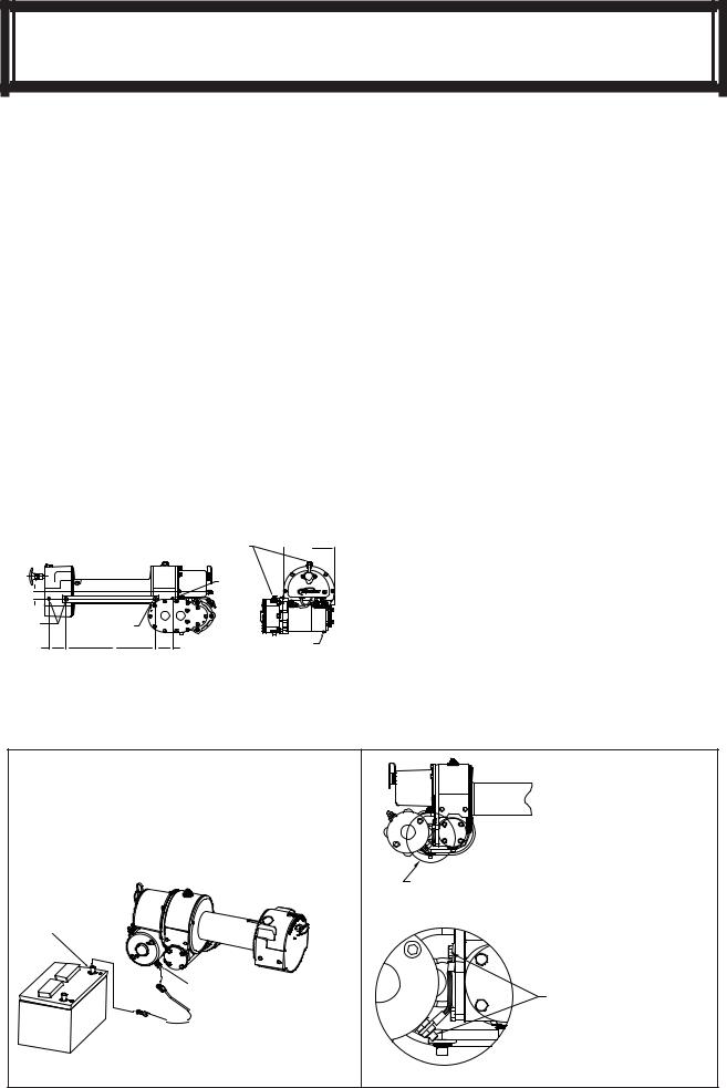
NOTE: If Ramsey Kits are not used, the winch must be mounted to angles (3/8” x 2 1/2” x 3” min) or in a frame with both sides of the clutch housing and gear housing bolted to the angles or frame.
See diagram below for recommended mounting dimensions. Note various thread depths of mounting holes and use correspondingly different bolt lengths for proper mounting.
1.12 |
|
|
|
.38-16UNC X .75" |
.38-16UNC X 1" |
|
|
DEEP THREADS |
DEEP THREADS |
|
|
(EACH SIDE) |
|
||
(EACH SIDE) |
|
||
2.50 |
A |
2.50 |
|
63,5 |
63,5 |
||
|
REMOVE RUBBER COVER FROM RELIEF FITTINGS BEFORE PUTTING
WINCH INTO USE. 7.44  188,9
188,9
.38-16UNC X .50" DEEP THREADS (EACH SIDE)
GROUND CABLE FROM MOTOR ISOLATED
GROUND TERMINAL TO NEGATIVE
BATTERY TERMINAL.
DIMENSIONS SHOWN ARE INCHES OVER MILLIMETERS
|
"A" Dimension |
|
Model |
In. ± .15 |
MM ± .4 |
RE 8/10/12 |
10.12 |
257.2 |
|
|
|
RE 12,000X |
13.12 |
333.3 |
|
|
|
Substitution of attaching hardware items
(bolts, nuts, or washers) different from those supplied with your winch mounting kit can lead to failure causing damage or serious injury. Use a socket head mounting bolt on side with Spur Gear Housing (see diagram) to prevent clearance problems.
Use SAE grade 5 bolts or better.
Electrical Connections and Operations
For normal self recovery work, your existing electrical system is adequate. Your battery must be kept in good condition. Afully charged battery and proper connections are essential. Run the vehicle engine during winching operation to keep battery charged.
Connect red cable from stud on plastic solenoid cover on winch to positive battery terminal. Important: Hold inner nut with end wrench while tightening outer nut.
Connect black cable from negative battery terminal to the motor isolated ground terminal. In applications where the chassis is non-grounded, a jumper wire (#440315) will be required between the winch and the motor isolated ground terminal. (See illustration below.)
WINCH WILL NOT OPERATE UNLESS
GROUND CABLE IS INSTALLED FROM THE ISOLATED GROUND TERMINAL TO THE NEGATIVE BATTERY POST.
(SEE DIAGRAM BELOW)
SEE ILLUSTRATION BELOW
NEGATIVE BATTERY POST
ISOLATED GROUND
TERMINAL


 GROUND CABLE
JUMPER CABLE (#440315) MUST BE INSTALLED ON WINCH FROM MOTOR ISOLATED GROUND STUD TO GEAR HOUSING COVER BOLT AS SHOWN FOR NON GROUNDED CHASSIS APPLICATIONS.
4
 Loading...