


|
English (Original Instructions) . . . . . . . . . . . . . . . |
1 |
OPERATING, SERVICE AND |
Français (Traduction des instructions originales) . . |
22 |
MAINTENANCE MANUAL |
Deutsch (Übersetzung der Originalanleitung) . . . . . |
42 |
|
Español(Traducción de las instrucciones originales) 62 |
|
MODEL RPH 133,4
INDUSTRIAL
PLANETARY WINCH
Intended Purpose: Vehicle recovery and pulling of loads
CAUTION: READ AND UNDERSTAND THIS MANUAL BEFORE INSTALLATION AND OPERATION OF WINCH. SEE WARNINGS!
RAMSEY WINCH COMPANY
P. O. Box 581510 - Tulsa OK 74158-1510 USA
Phone: (918) 438-2760 Fax: (918) 438-6688
Visit us at http://www.ramsey.com
Ramsey Authorized Representative in the Community:
(Please contact for regulatory inquiries only. )
Alura Group BV |
|
P.O. Box 18626 |
|
2502 EP The Hague |
|
The Netherlands |
|
Tel: (31) (0) 70 362-4896 |
|
Fax: (31) (0) 70 346-7299 |
OM-914217-1112-B |

|
4707 N. Mingo |
Tulsa, Oklahoma 74117 |
(918) 438-2760 |
|
|
||
|
|
|
|
|
|
|
|
|
|
|
|
|
|
|
|
EC DECLARATION OF CONFORMITY |
|
DÉCLARATION DE CONFORMITÉ EC |
|
||||
as defined by Machinery Directive 2006/42/EC |
|
aux termes de la directive Machines 2006/42/EC |
|
||||
Here with we declare that winch model RPH 133,4 com- |
Nous déclarons par la présente que le modèle de treuil |
|
|||||
plies with the following directive provided that the USER |
RPH 133,49 est conforme à la directive suivante, sous |
|
|||||
complies with all responsibilities described in the Owner’s |
réserve que l’UTILISATEUR ait assumé toutes les respons- |
|
|||||
Manual: |
|
abilités figurant dans le manuel de l’utilisateur : |
|
||||
2006/42/EC |
|
2006/42/EC |
|
|
|
||
Applied harmonized standards: |
|
Normes harmonisées appliquées : |
|
||||
EN 14492-1:2006 |
|
EN 14492-1:2006 |
|
|
|
||
|
|
|
|
|
|
|
|
Power-Driven Winches |
|
Treuils motorisés |
|
|
|
||
ISO 9001:2000 |
|
|
|
|
|||
|
ISO 9001:2000 |
|
|
|
|||
Quality Management Systems |
|
|
|
|
|||
|
Systèmes de gestion de la qualité - Exigences |
|
|||||
Requirements |
|
|
|||||
|
|
|
|
|
|||
|
|
|
|
|
|
|
|
EC-KONFORMITÄTSERKLÄRUNG |
|
DECLARACIÓN EC DE CONFORMIDAD |
|
||||
gemäß Maschinenrichtlinie 2006/42/EC |
|
según se define en la directiva de máquinas 2006/42/EC |
|
||||
Hiermit erklären wir, dass das Windenmodell |
|
Con la presente declaramos que el modelo de cabestrante |
|
||||
RPH 133,4 der folgenden Richtlinie entspricht, sofern |
|
RPH 133,4 se halla en conformidad con la siguiente directiva |
|
||||
der BENUTZER alle Anweisungen im Benutzerhandbuch |
siempre que el USUARIO cumpla todas las responsabili- |
|
|||||
befolgt: |
|
dades descritas en el Manual del propietario: |
|
||||
2006/42/EC |
|
2006/42/EC |
|
|
|
||
Angewandte harmonisierte Normen: |
|
Normas armonizadas aplicadas: |
|
|
|
||
EN 14492-1:2006 |
|
EN 14492-1:2006 |
|
|
|
||
Kraftgetriebene Winden |
|
Cabestrantes accionados mecánicamente |
|
||||
ISO 9001:2000 Qualitätsmanagementsysteme - |
|
ISO 9001:2000 |
|
|
|
||
Anforderungen |
|
Requisitos de los Sistema de gestión de la calidad |
|
||||
|
|
|
|
|
|
|
|
Ramsey Authorized Representative in the Community / Ramsey Représentant autorisé dans la comuauté / Ramsey Bevollmächtigter in der Europäischen Union / Ramsey Representante autorizado en la comunidad.
(Please contact for regulatory inquiries only. / Veuillez prendre contact uniquement pour des questions réglementaires.) (Bitte nur bei Regulierungsfragen kontaktieren. / Póngase en contacto sólo por cuestiones de reglamentación.)
Alura Group BV
P.O. Box 18626
2502 EP The Hague
The Netherlands
Tel: (31) (0) 70 362-4896
Fax: (31) (0) 70 346-7299
Serial Number / Numéro de série/ Seriennummer/ Número de Serie:_____________________
Signature / Signature / Unterschrift / Firma: |
Date / Date / Datum / Fecha: |
|
|
|
Todd Brady |
06-13-11 |
|
|
|
|
Engineering Manager / Directeur technique/ Technischer Leiter/ Director de ingeniería |
|
||
TABLE OF CONTENTS
SPECIFICATIONS . . . . . . . . . . . . . . . . . . . . . . . . . . . . . . . . . . . . . . . . . . . . . . . . . . . . . . . . . . .1 WARNINGS . . . . . . . . . . . . . . . . . . . . . . . . . . . . . . . . . . . . . . . . . . . . . . . . . . . . . . . . . . . . . . . .1 USER’S RESPONSIBILITY FOR CE COMPLIANCE . . . . . . . . . . . . . . . . . . . . . . . . . . . . . . . .1 HYDRAULIC SYSTEM REQUIREMENTS . . . . . . . . . . . . . . . . . . . . . . . . . . . . . . . . . . . . . . . . .2 PERFORMANCE CHARTS . . . . . . . . . . . . . . . . . . . . . . . . . . . . . . . . . . . . . . . . . . . . . . . . . . . .2 CLUTCH OPERATION . . . . . . . . . . . . . . . . . . . . . . . . . . . . . . . . . . . . . . . . . . . . . . . . . . . . . . . .3 WINCH FRAME MOUNTING . . . . . . . . . . . . . . . . . . . . . . . . . . . . . . . . . . . . . . . . . . . . . . . . . . .3 ROPE INSTALLATION . . . . . . . . . . . . . . . . . . . . . . . . . . . . . . . . . . . . . . . . . . . . . . . . . . . . . . . .3 WINCH OPERATION . . . . . . . . . . . . . . . . . . . . . . . . . . . . . . . . . . . . . . . . . . . . . . . . . . . . . . . . .3 MAINTENANCE . . . . . . . . . . . . . . . . . . . . . . . . . . . . . . . . . . . . . . . . . . . . . . . . . . . . . . . . . . . . .4 END OF SERVICE MEASURES . . . . . . . . . . . . . . . . . . . . . . . . . . . . . . . . . . . . . . . . . . . . . . . .4 TROUBLE SHOOTING GUIDE . . . . . . . . . . . . . . . . . . . . . . . . . . . . . . . . . . . . . . . . . . . . . . . . .4 INSTRUCTIONS FOR OVERHAUL . . . . . . . . . . . . . . . . . . . . . . . . . . . . . . . . . . . . . . . . . . .5-12 MOUNTING CONFIGURATIONS . . . . . . . . . . . . . . . . . . . . . . . . . . . . . . . . . . . . . . . . . . . . . . .12 DIMENSIONAL DRAWINGS . . . . . . . . . . . . . . . . . . . . . . . . . . . . . . . . . . . . . . . . . . . . . . . .13-14 PARTS LIST AND PART DRAWING . . . . . . . . . . . . . . . . . . . . . . . . . . . . . . . . . . . . . . . . . .15-16 ROPE TENSIONER OVERHAUL AND INSTALLATION . . . . . . . . . . . . . . . . . . . . . . . . . . . . .17 ROPE TENSIONER PARTS LIST AND PARTS DRAWING . . . . . . . . . . . . . . . . . . . . . . . . . . .18 CE DECLARATION OF CONFORMITY . . . . . . . . . . . . . . . . . . . . . . . . . . . . . . . . . . . . . . . . . .19

SPECIFICATIONS*
First Layer Line Pull |
|
|
|
|
133,4 kN (30000 lb) |
|
|
|
|
|
|
||
Noise Level |
|
|
|
|
|
76 db |
|
|
|
|
|
|
|
Ambient Temperature Range |
|
|
|
-28C to 60C (-20F to 140F) |
||
|
|
|
|
|
|
|
Gear Reduction |
|
|
|
|
31:89:1 |
|
Weight (without rope) |
|
|
|
|
|
261 kg (575 lb) |
|
|
|
|
|
|
|
LAYER OF ROPE |
|
1 |
2 |
3 |
|
4 |
|
|
|
|
|
|
|
Line pull per layer |
kN |
133,4 |
111,2 |
95,3 |
|
83,3 |
|
|
|
|
|
|
|
lb |
30,000 |
24,900 |
21,400 |
|
18,700 |
|
|
|
|||||
|
|
|
|
|
|
|
|
|
|
|
|
|
|
* Rope Capacity per Layer |
m |
10 |
25 |
42 |
|
62 |
|
|
|
|
|
|
|
ft |
35 |
85 |
140 |
|
205 |
|
|
|
|||||
|
|
|
|
|
|
|
* Line Speed at 56,7 LPM (15 |
MPM |
5,5 |
6,3 |
7,2 |
|
8,5 |
GPM) |
FPM |
18 |
21 |
24 |
|
28 |
|
|
|
|
|
|
|
* These specifications are based on recommended 20 mm (.787") 1960 grade wire rope and a 195 cc (11.9 cu in /Rev) motor.
WARNINGS:
THE USER SHALL ENSURE THAT THE OPERATING PERSONNEL ARE GIVEN THE NECESSARY TRAINING. THE OPERATOR SHALL ALWAYS WORK IN COMPLIANCE WITH THE OPERATING INSTRUCTIONS.
A MOTOR SPOOL (OPEN CENTER) DIRECTIONAL CONTROL VALVE IS REQUIRED FOR BRAKE OPERATION. CLUTCH MUST BE FULLY ENGAGED BEFORE STARTING THE WINCH.
DO NOT DISENGAGE CLUTCH UNDER LOAD.
STAY OUT FROM UNDER AND AWAY FROM RAISED LOADS.
STAND CLEAR OF ROPE WHILE PULLING. DO NOT TRY TO GUIDE ROPE.
DO NOT USE WINCH TO LIFT, SUPPORT, OR OTHERWISE TRANSPORT PERSONNEL.
A MINIMUM OF 2 WRAPS OF ROPE AROUND THE DRUM BARREL IS NECESSARY TO HOLD THE LOAD. AVOID CONDITIONS WHERE LOAD SHIFTS OR JERKS OCCUR. EXCESSIVE “INCHING” SHALL BE AVOIDED.
USER’S RESPONSIBILITY FOR CE COMPLIANCE
1.Use only a motor spool (open center) control valve Per Hydraulic System Requirements.
2.If a remote-operated winch control valve is used, refer to Hydraulic System Requirements for Emergency Stop components to be installed.
3.Adjust system relief pressure per Hydraulic System Requirements
4.Mount winch per Winch Mounting Instructions.
5.Install 20 mm (.787 inch), grade 1960 wire rope. Maximum rope length of 62 M (205 ft) for four layers maximum. Attach rope to the drum per Rope Installation Instructions. Hook must have a safety latch and a minimum breaking strength of 334 kN.
1
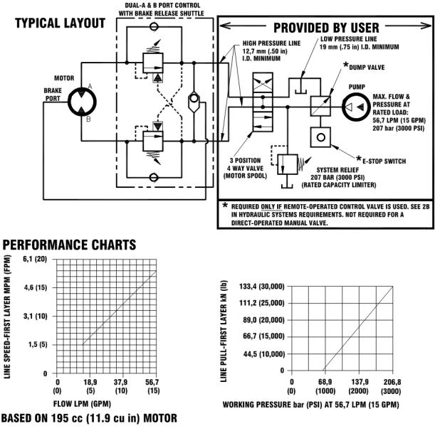
Refer to the performance charts below to properly match your hydraulic system to the winch performance. The charts consist of: (1) Line Pull first layer kN (lb) vs. Working Pressure bar (PSI). (2) Line Speed, first layer MPM (FPM) vs. flow LPM (GPM).
HYDRAULIC SYSTEM REQUIREMENTS
1.Motor spool (open center) control valve
2.Emergency Stop:
A.If winch is controlled by a direct-operated manual valve, that valve serves as the E-stop.
B.If a remote operated control valve is used, a solenoid-operated hydraulic dump valve, normally open to tank, and an emergency stop switch (to open the dump valve) is required. The E-stop switch is to be normally closed and have a red, resettable push button actuator with a yellow background. The E-stop switch must be easily accessible to the operator.
3.Relief valve set to 207 bar (3000 psi) which is the rated capacity limiter.
4.Flow rate of 56,7 LPM (15 GPM) maximum. Do not exceed 75,7 LPM (20 GPM) or motor and winch may be damaged.
5.Hydraulic fluid with a viscosity between 20-43 cSt (100-200 SUS). Maximum operating temperature 85C (180F). Cleanliness level of ISO 17-14 or better.
2
WINCH FRAME MOUNTING
Use (8) 5/8 inch diameter grade 5 or better bolts to attach mounting frame to wrecker.
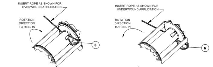
ROPE INSTALLATION
The RPH 133,4 winch has two tapered pockets cast into the drum. One pocket is for installations with the wire rope wound over the drum. The other pocket is for an underwound wire rope.
1.Unwind rope by rolling it out along the ground to prevent kinking. Securely wrap end of wire rope, opposite hook, with plastic or similar tape to prevent fraying.
2.Slide the wire rope through narrow end of the pocket against the drum flange and wrap the wire rope around the anchor "puck" and pull the wire rope and anchor back into the wide end of the pocket. Use a soft hammer to drive the back side of the wire rope, firmly seating the wire rope and anchor, into the pocket.
3.Carefully run winch in the "reel-in" direction. Keeping tension on end of rope, spool all the rope onto the rope drum, taking care to form neatly wrapped layers.
CLUTCH OPERATION
To engage clutch:
1.Move the clutch control valve to the "clutch-engaged" position.
2.Anytime the temperature is below freezing, run motor in the "rope out" direction only until the drum starts to turn.
2a. In extreme cold temperatures (below -18o C/ 0o F), pull out on the rope by hand only until the drum starts to turn.
3.Wait at least 3 seconds for the clutch to fully engage, after which the winch is ready to winch in the rope. WARNING: Do not attempt to engage the clutch by first running the winch motor and then moving the
clutch control valve to the "clutch-engaged" position while the motor is running. Do not start picking up
the load at the same time the clutch is being engaged.
To disengage clutch:
1.Run the winch in the "rope out" direction until the load is off the rope.
2.Move the clutch control valve to the "clutch-disengaged" position.
3.The rope may now be pulled off by hand.
WINCH OPERATION
The best way to get acquainted with how your winch operates is to make test runs before you actually use it. Plan your test in advance. Remember, you hear your winch, as well as see it operate. Get to recognize the sounds of a light steady pull, a heavy pull, and sounds caused by load jerking or shifting. Gain confidence in operating your winch and its use will become second nature with you.
The uneven spooling of rope, while pulling a load, is not a problem, unless there is a rope pileup on one end of drum. If this happens reverse the winch to relieve the load and move your anchor point further to the center of the vehicle. After the job is done you can unspool and rewind for a neat lay of the rope.
3
MAINTENANCE
Adhering to the following maintenance schedule will keep your winch in top condition and performing as it should with a minimum of repair.
A. WEEKLY
1.Check the oil level and maintain it to the oil level plug. If oil is leaking out, determine location and repair.
2.Check the pressure relief plug in top of the gear housing. Be sure that it is not plugged.
3.Lubricate rope with light oil.
B. MONTHLY
1.Check the winch mounting bolts. If any are missing, replace them and securely tighten any that are loose. Use grade 5 or better bolts.
2.Inspect the rope. If the rope has become frayed with broken strands, replace immediately.
C. ANNUALLY
1.Drain the oil from the winch annually or more often if winch is used frequently.
2.Fill the winch to the oil level plug with clean kerosene. Run the winch a few seconds with no load in the reel in direction. Drain the kerosene from the winch.
3.Refill the winch to the oil level plug with all purpose SAE 80W-140 gear oil.
4.Inspect frame and surrounding structure for cracks or deformation.
END OF SERVICE MEASURES
When winch reaches the end of it’s servicable life, dispose of per local environmental regulations.
TROUBLE SHOOTING GUIDE
________________________________________________________________________________
CONDITIONS POSSIBLE CAUSE CORRECTION
________________________________________________________________________________
OIL LEAKS FROM WINCH |
1. |
Seals damaged or worn. |
1. |
Replace seal. |
|
2. Too much oil. |
2. |
Drain excess oil. Refer to |
|
|
|
|
|
OPERATION. |
|
3. |
Damaged gasket. |
3. |
Replace gasket. |
--------------------------------------------------------------------------------------------------------------------------------------
WINCH RUNS TOO SLOW |
1. |
Low flow rate |
1. |
Check flow rate.Refer to flow |
HYDRAULIC SYSTEMS |
|
|
|
flow chart page 2. |
|
2. |
Hydraulic motor worn out. |
2. |
Replace motor. |
--------------------------------------------------------------------------------------------------------------------------------------
ROPE DRUM WILL NOT |
1. Clutch not disengaged |
1. Check air pressure to clutch |
FREESPOOL |
|
cylinder 6,2 bar (90 PSI) mini |
|
|
mum required-Refer to page |
2.If equipped with air tensioner, too much force on tensioner bar.
2.Reduce air pressure to tensioner actuators.
-------------------------------------------------------------------------------------------------------------------------------------
BRAKE WILL NOT RELEASE 1. Air in hydraulic system |
1. Bleed air from brake. Refer |
|
to page 2. |
4
INSTRUCTIONS FOR OVERHAUL
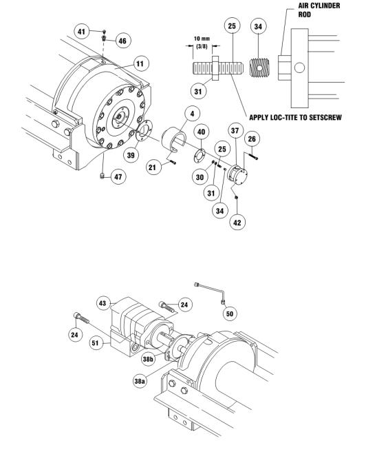
1.Drain oil from gear housing item #11 by removing plug item #47 from end bearing. Remove reducer and relief fitting items #41 & #46.
If new air cylinder is required, remove air cylinder item #37 from adapter item #4 by removing (4) capscrews item #26. Remove breather vent item #42. Remove washer item #30, nut and setscrew items #31 & #25 and insert item #34 from end of air cylinder rod. Apply Loc-tite to threads of nut item #31 and thread onto setscrew item #25 to 10 mm (3/8 inch) from drive end, as shown below. Apply Loc-tite to threads of setscrew and thread insert item #34 over end of setscrew and against nut. Use setscrew and nut to thread insert item #34 into end of air cylinder rod. Tighten nut against cylinder rod, keeping 10 mm (3/8 inch) distance from drive end of setscrew to nut. Be sure breather vent item #42, and relief fitting item #41are not damaged and in good operating condition. Remove and replace if necessary. Remove air cylinder adapter item #4 and gasket item #40 from gear housing cover by unscrewing (4) capscrews item #21.
2.Disconnect tube item #50 from elbow item #35 and fitting item #36 on bottom of brake item #38. Remove motor item #43 and gasket item #38b by removing (2) capscrews item #24. Remove valve item #51, if needed, from motor by loosening (3) capscrews item #22 (not shown).
5
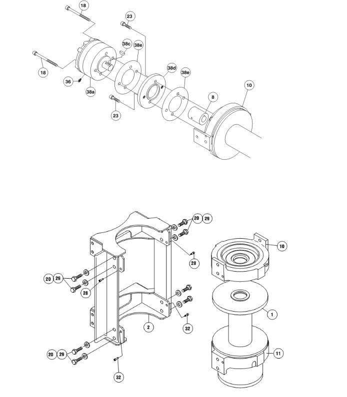
3.Remove brake assembly screws item #18 from brake #38a to access (2) mounting screws item #23 attaching brake adapter plate #38d to end bearing item #10. CAUTION: Brake is spring loaded by clutch spring and must be restrained against end bearing as mounting screws item #23 are removed. Remove coupling item #8 and gasket item #38e from end bearing. Take note of mounting configuration for proper mounting of parts during re-assembly.
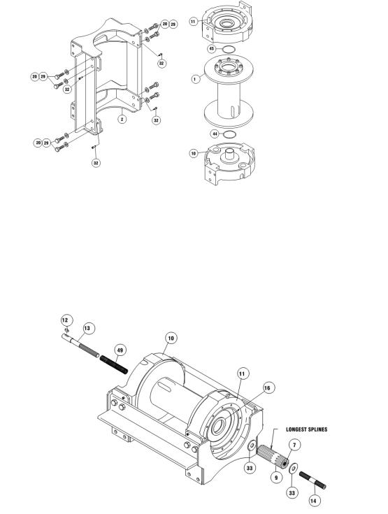
4.Remove winch from upright mounting frame item #2 by removing (8) capscrews item #20, (8) lockwashers item #29 and (4) shoulder bolts item #32. Pull motor end bearing item #10 from drum assembly item #1.
6
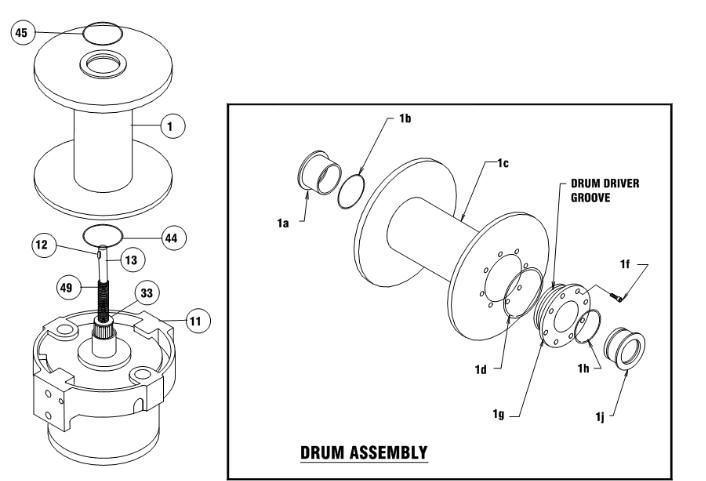
5.Pull drum assembly item #1 upward from end bearing item #11. Remove quad-rings item #44 & #45 from grooves in drum bushings. Remove input shaft item #13, clutch spring item #49 and washer item #33 from end bearing item #11. Examine key item #12 and input shaft for signs of wear, replace if damaged.
Examine drum assembly item #1 for signs of wear. If splines inside of drum driver #1g are damaged, it must be replaced. Remove drum driver #1g by unscrewing (8) capscrews #1f. Place well oiled o-ring #1d into drum driver groove and attach driver to drum #1c using (8) capscrews #1f.
Torque capscrews #1f to 163 Nm (120 ft lb) each, in criss-cross pattern.
Press old bushings #1a and #1j from drum #1c and drum driver #1g. Remove o-rings #1b and 1h from grooves in drum #1c and drum driver bushing #1j. Place well oiled o-rings #1b and #1h into grooves in drum #1c and outer diameter of drum driver bushing #1j. Press new bushing #1a into end of drum #1c opposite drum driver #1g and press bushing #1j into drum driver #1g until flange of bushings are flush against drum #1c and driver #1g.
7
6.Remove output coupling item #9 and coupling shaft item #7 from end bearing item #11. Examine bearings item #15, pressed in output coupling item #9, for signs of wear. Replace bearings, if necessary, by pressing old bearings from coupling and press new bearings item #15 into each end of output coupling item #9. Place coupling shaft item #7 into bearings item #15.
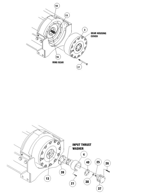
7.Remove (12) capscrews item #17 to pull gear housing cover from ring gear. Remove input thrust washer, sun gear and carrier assemblies from inside of ring gear. Remove ring gear from end bearing item #11. Examine shifter shaft item #14 for signs of wear, replace if necessary. Examine bushing item #16 for signs of wear. Replace bushing, if necessary, by pressing old bushing from housing and pressing new bushing into place.
8
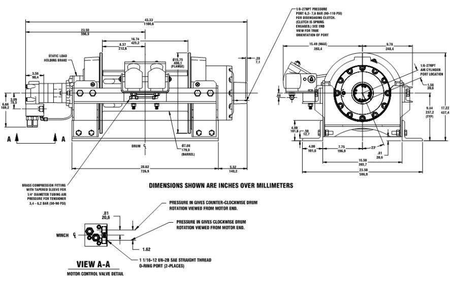
8.NOTE: DETERMINE MOUNTING CONFIGURATION OF WINCH (R.H. or L.H. MOUNTED) BEFORE ATTACHING UPRIGHT FRAME TO WINCH, TO ASSURE PARTS ARE MOUNTED TO PROPER SIDE, REFER TO WINCH MOUNTING CONFIGURATIONS, STEP 16 PAGE 12.
Seat well oiled quad-rings item #44 & #45 into groove of bushing in each end of drum assembly item #1, as shown. Carefully set drum assembly item #1 down over motor end bearing item #10. Lift gear housing end bearing item #11 and set into place on drum assembly. Attach upright frame item #2 to end bearings. Install (4) shoulder bolts item #32 and hand tighten. Install (8) capscrews with lockwashers item #20 & #29. Tighten (4) inner-most capscrews securely, check rotation of rope drum. Tighten (4) outer-most capscrews securely, check rotation of rope drum. Torque capscrews, in previous inner-most then outer-most pattern, to 339 Nm (250 ft lb) each. Torque (4) shoulder bolts to 41 Nm (30 ft lb) each. Make sure rope drum assembly rotates freely at this point.
9.Gently tap key item #12 into keyway of input shaft item #13. Liberally apply grease to shoulder of input shaft item #13. Place spring item #49 over splined end of shaft. Use grease to hold spring in place on shaft. Place spring and splined end of shaft through motor end bearing item #10 and drum until shaft extends through bushing item #16. Place clutch washer item #33 over splined end of shaft and against spring.
Place end of output coupling assembly item #9, with longest splines, through end bearing bushing item #16 and mesh shaft coupling spline with splined end of shaft. Place short splined end of shifter shaft item #14 through washer item #33 and into shaft coupling item #7, meshing splines of shifter shaft with splines in shaft coupling.
9
10.Apply RTV sealing compound to ring gear mounting surface of end bearing item #10. Place ring gear onto end bearing, aligning holes in ring gear with holes and gear housing end bearing. Use
(2) capscrews to temporarily secure ring gear to end bearing.
Place (2) gear carrier assemblies into ring gear meshing carrier gears with ring gear. Remove
(2) temporary capscrews, making sure that ring gear and carrier assemblies are securely against end bearing item #10. Apply RTV sealing compound to cover mounting surface of ring gear item #3) and attach cover to ring gear. Use (12) capscrews item #17 to secure gear box to gear housing end bearing. Torque capscrews to 53 Nm (39 ft lb) each, in criss-cross pattern.
11.Slide input sun gear over shifter shaft item #13 and mesh with teeth of input carrier. Apply grease to input thrust washer and place into slots of air cylinder adapter item #4. Place gasket item #40 into position on gear box cover with sealer and attach adapter to cover using (4) capscrews item #21 Apply Loctite PST thread sealer to threads of capscrews. Torque capscrews to 18 Nm (13 ft lb) each, in criss-cross pattern.
Pull rod from air cylinder as far as possible. Slide washer item #30 over setscrew item #25 and against nut attached to air cylinder rod. Place setscrew into hole of shifter shaft item #13. Attach new air cylinder item #37 and gasket item #40 with sealer, to adapter using (4) capscrews item #26. Apply Loctite PST thread sealer to threads of capscrews. Torque capscrews to 7 Nm (5 ft lb) each, in criss-cross pattern.
10
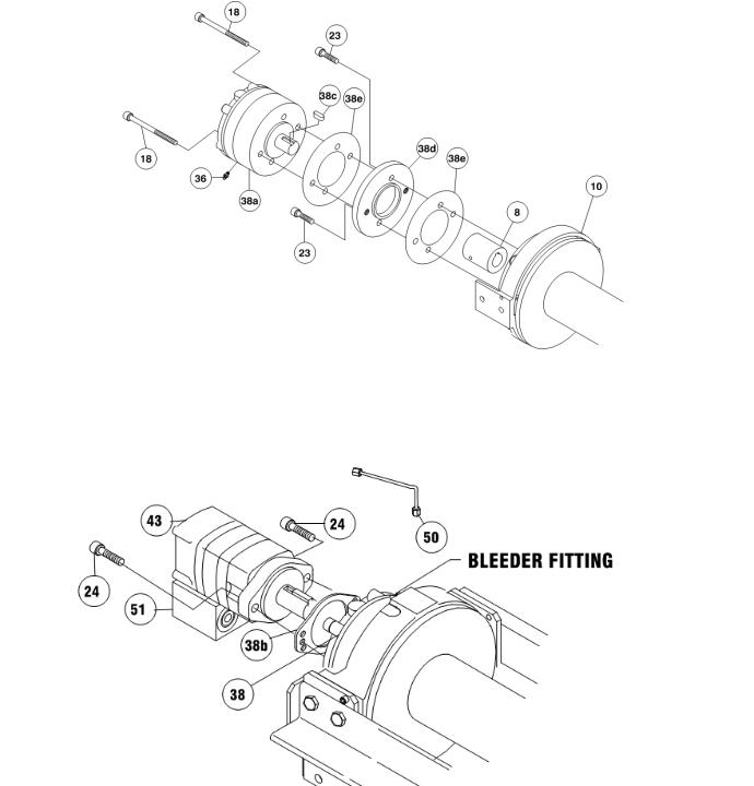
12. Align key way of coupling with key on end of input shaft inside end bearing assembly. Slide coupling over end of shaft. Place gasket item #38e into position on motor mounting surface of end bearing item #10. Use (2) screws item #23 to attach adapter plate item #38d to motor end bearing. Torque capscrews to 115 Nm (85 ft lb) each. Place second gasket item #38e on adapter plate. Insert brake shaft with key item #38c into coupling. Re-attach brake item #38a to adapter plate using brake assembly screws item #18. Torque capscrews to 132 Nm (97 ft lb) each.
Note: Care must be taken to assure brake assembly and adapter plate are seated properly prior to installing assembly bolts item #18. Damage will occur to rotor stack or shaft snap ring if not properly installed.
13.Attach motor item #43 with gasket item #38b to brake item #38. Use (2) capscrews item #24 and torque to 100 Nm (74 ft lb) each. Securely connect tube item #50 to elbow item #35 in bottom of valve and fitting item #36 in bottom of brake item #38.
11
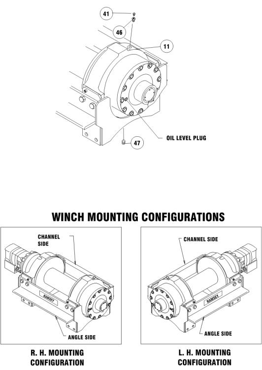
14.Apply Permatex to threads of plug item #47. Thread plug into tapped hole in bottom of gear housing end bearing item #11. Pour approx. 1.2 liters (2.50 pints) of SAE 80W-140 oil into end bearing. Check oil level by removing oil plug noted below. Insert relief fitting item #41 and thread reducer item #46 into end bearing at oil fill hole.
Install winch and connect pressure lines. Bleed pressure release section of brake by loosening bleeder fitting on brake and allowing air to escape while slowly appling hydraulic system pressure to the winch (refer to bleeder fitting in step 13). Apply at least 15,9 bar (230 PSI) pressure to release brake and verify that brake releases, by observing that the winch drum rotates
15.Check proper operation of clutch by applying air pressure to clutch air cylinder to disengage clutch. Verify that winch freespools. Re-engage clutch. A loud noise should be heard when clutch engages. Winch drum should not freespool.
16.Operate winch forward and reverse to verify that drum rotates.
12
13
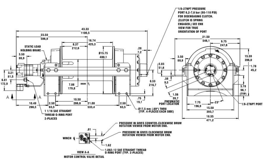
RPH 133,4 DIMENSIONAL
(WITH FOOT MOUNTING ANGLES AND AIR TENSIONER)
14
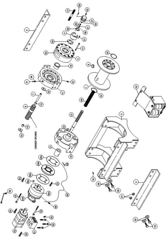
RPH 133,4 DIMENSIONAL
(WITHOUT FOOT MOUNTING ANGLES)
RPH 133,4
15

16
ROPE TENSIONER OVERHAUL
Refer to the Rope Tensioner Parts Diagram on the following page for the assembly of the Rope Tensioner.
The rope tensioner requires an independent, adjustable air supply of between 3,4 bar (50 PSI) and 6,2 bar (90 PSI).
Do not operate the winch with the tensioner energized against a bare drum. The winch should only be operated with at least one wrap of rope around the drum with the tensioner energized.
1.To remove the air tensioner from the winch, disconnect the air supply from the tensioner. Remove the capscrews item #8), lockwashers item #11 and nuts item #9 that mount the tensioner to the winch frame. Disassemble the tensioner as shown on the following page and remove any parts that are worn.
2.Re-assemble the tensioner assembly. Mount the tensioner to the winch frame, placing the spacers item #4 between the tensioner bracket and the winch frame. Center the tensioner bar item #2 between the drum flanges using a tape measure or scale. Tighten the mounting bolts to 102 Nm (75 ft lb) of torque.
3.Install the rope on the drum. After a few wraps of the rope are wound onto the drum, connect the air supply to the tee fitting item #14 to energize the tensioner against the drum. As the rope winds onto the drum, watch the tensioner to ensure that it moves freely and does not touch either drum flange.
4.Adjust the air supply until the rope does not “bird nest” when it is freespooling.
17
|
|
PARTS LIST FOR TENSIONER ASSEMBLY |
|
ITEM NO. |
QTY |
PART NUMBER |
DESCRIPTION |
1 |
1 |
265021 |
TENSIONER ASSEMBLY |
2 |
1 |
304186 |
TENSION BAR |
3 |
1 |
346046 |
PIN |
4 |
1 |
362295 |
SPACER |
5 |
1 |
365038 |
TUBE |
6 |
1 |
408227 |
BRACKET ASSEMBLY |
7 |
3 |
414278 |
CAPSCREW 3/8-16NC X 3/4 LG HXHD GR5 |
8 |
2 |
414545 |
CAPSCREW 1/2-13NC X 3.5 LG HX HD GR5 |
9 |
2 |
418069 |
NUT 1/2-13NC HX |
10 |
4 |
418080 |
NUT 5/8-11NC HX |
11 |
2 |
418217 |
LOCKWASHER 1/2 |
12 |
2 |
418223 |
FLATWASHER 1/2 |
13 |
2 |
424005 |
COTTER PIN |
14 |
1 |
432032 |
FITTING - TEE |
15 |
1 |
432033 |
FITTING - ELBOW |
16 |
2 |
433022 |
AIR ACTUATOR |
17 |
2 |
468016 |
PIPE PLUG |
18
MANUEL D'EXPLOITATION, |
English (Original translation) . . . . . . . . . . . . . . . . . |
1 |
DE DÉPANNAGE ET |
Français (Traduction des instructions originales) . . |
22 |
D'ENTRETIEN |
Deutsch (Übersetzung der Originalanleitung) . . . . . |
42 |
|
Español(Traducción de las instrucciones originales).62 |
|
TREUIL À PLANÉTAIRE
INDUSTRIEL, MODÈLE
RPH 133,4
Utilisation prévue : dépannage de véhicule et traction de charges
MISE EN GARDE : LIRE ET COMPRENDRE CE MANUEL AVANT D'INSTALLER ET D'UTILISER LE TREUIL. LIRE LES AVERTISSEMENTS !
RAMSEY WINCH COMPANY
P.O. Box 581510 - Tulsa, OK 74158-1510 États-Unis
Téléphone : (918) 438-2760 Fax : (918) 438-6688
Nous visiter à http://www.ramsey.com
Ramsey Représentant autorisé dans la comuauté:
(Veuillez prendre contact uniquement pour des questions réglementaires.)
Alura Group BV |
|
P.O. Box 18626 |
|
2502 EP The Hague |
|
The Netherlands |
|
Tel: (31) (0) 70 362-4896 |
|
Fax: (31) (0) 70 346-7299 |
OM-914217-1112-B |
TABLE DES MATIÈRES
CARACTÉRISTIQUES TECHNIQUES . . . . . . . . . . . . . . . . . . . . . . . . . . . . . . . . . . . . . . . . . . .20 AVERTISSEMENTS . . . . . . . . . . . . . . . . . . . . . . . . . . . . . . . . . . . . . . . . . . . . . . . . . . . . . . . . .20 RESPONSABILITÉ DE L'UTILISATEUR POUR LA CONFORMITÉ CE . . . . . . . . . . . . . . . . .20 CARACTÉRISTIQUES DU SYSTÈME HYDRAULIQUE . . . . . . . . . . . . . . . . . . . . . . . . . . . . .21 DIAGRAMMES DE PERFORMANCES . . . . . . . . . . . . . . . . . . . . . . . . . . . . . . . . . . . . . . . . . .21 FONCTIONNEMENT DE L'EMBRAYAGE . . . . . . . . . . . . . . . . . . . . . . . . . . . . . . . . . . . . . . . .22 MONTAGE DU CADRE DU TREUIL . . . . . . . . . . . . . . . . . . . . . . . . . . . . . . . . . . . . . . . . . . . .22 POSE DU CÂBLE . . . . . . . . . . . . . . . . . . . . . . . . . . . . . . . . . . . . . . . . . . . . . . . . . . . . . . . . . . .22 FONCTIONNEMENT DU TREUIL . . . . . . . . . . . . . . . . . . . . . . . . . . . . . . . . . . . . . . . . . . . . . .22 ENTRETIEN . . . . . . . . . . . . . . . . . . . . . . . . . . . . . . . . . . . . . . . . . . . . . . . . . . . . . . . . . . . . . . .23 MESURES DE MISE HORS SERVICE . . . . . . . . . . . . . . . . . . . . . . . . . . . . . . . . . . . . . . . . . .23 GUIDE DE DÉPANNAGE . . . . . . . . . . . . . . . . . . . . . . . . . . . . . . . . . . . . . . . . . . . . . . . . . . . . .23 INSTRUCTIONS DE RÉVISION . . . . . . . . . . . . . . . . . . . . . . . . . . . . . . . . . . . . . . . . . . . . .24-31 CONFIGURATIONS DE MONTAGE . . . . . . . . . . . . . . . . . . . . . . . . . . . . . . . . . . . . . . . . . . . . .31 PLANS COTÉS . . . . . . . . . . . . . . . . . . . . . . . . . . . . . . . . . . . . . . . . . . . . . . . . . . . . . . . . . .32-33 LISTE ET SCHÉMA DES PIÈCES . . . . . . . . . . . . . . . . . . . . . . . . . . . . . . . . . . . . . . . . . . .34-35 RÉVISION ET INSTALLATION DU TENDEUR DE CÂBLE . . . . . . . . . . . . . . . . . . . . . . . . . . .36 LISTE ET SCHÉMA DES PIÈCES DU TENDEUR DE CÂBLE . . . . . . . . . . . . . . . . . . . . . . . .37 DÉCLARATION DE CONFORMITÉ CE . . . . . . . . . . . . . . . . . . . . . . . . . . . . . . . . . . . . . . . . . .38

CARACTÉRISTIQUES TECHNIQUES*
Traction du câble, première couche |
|
|
|
|
133,4 kN (13 608 kg) |
|
|
|
|
|
|
||
Niveau sonore |
|
|
|
|
|
76 dB |
|
|
|
|
|
|
|
Plage de températures ambiantes |
|
|
|
|
|
-28 ºC à 60 ºC |
|
|
|
|
|
|
|
Poids de démultiplication |
|
|
|
|
31:89:1 |
|
(sans le câble) |
|
|
|
|
|
261 kg |
|
|
|
|
|
|
|
COUCHE DE CÂBLE |
|
1 |
2 |
3 |
|
4 |
|
|
|
|
|
|
|
Traction du câble, par couche |
kN |
133,4 |
111,2 |
95,3 |
|
83,3 |
|
|
|
|
|
|
|
lb |
30,000 |
24,900 |
21,400 |
|
18,700 |
|
|
|
|||||
|
|
|
|
|
|
|
|
|
|
|
|
|
|
*Capacité de câble par couche |
m |
10 |
25 |
42 |
|
62 |
pi |
35 |
85 |
140 |
|
205 |
|
|
|
|||||
|
|
|
|
|
|
|
*Vitesse du câble à 56 l/min |
m/min |
5,5 |
6,3 |
7,2 |
|
8,5 |
|
|
|
|
|
|
|
pi/min |
18 |
21 |
24 |
|
28 |
|
|
|
|||||
|
|
|
|
|
|
|
* Ces spécifications sont basées sur le câble métallique de calibre 1960 de 20 mm recommandé et sur un moteur de 195 cm3.
AVERTISSEMENTS :
L'UTILISATEUR DOIT VEILLER À CE QUE TOUT OPÉRATEUR REÇOIVE LA FORMATION NÉCESSAIRE. L'OPÉRATEUR DOIT TOUJOURS TRAVAILLER EN CONFORMITÉ AVEC LES INSTRUCTIONS D'UTILISATION.
UN DISTRIBUTEUR À TIROIR CYLINDRIQUE DE MOTEUR (CENTRE OUVERT) EST NÉCESSAIRE POUR LE FONCTIONNEMENT DU FREIN.
L'EMBRAYAGE DOIT ÊTRE COMPLÈTEMENT ENCLENCHÉ AVANT DE DÉMARRER LE TREUIL. NE JAMAIS RELÂCHER L'EMBRAYAGE EN PRÉSENCE D'UNE CHARGE.
NE JAMAIS SE PLACER SOUS UNE CHARGE SOULEVÉE NI À PROXIMITÉ.
RESTER À L'ÉCART DU CÂBLE LORS DU TREUILLAGE. NE PAS ESSAYER DE GUIDER LE CÂBLE. NE PAS UTILISER LE TREUIL POUR SOULEVER, MAINTENIR OU TRANSPORTER DES PERSONNES.
IL CONVIENT DE CONSERVER AU MINIMUM DEUX TOURS DE CÂBLE AUTOUR DU TAMBOUR POUR MAINTENIR LA CHARGE.
ÉVITER TOUTE SITUATION DE DÉPLACEMENT DE LA CHARGE OU D'À-COUPS. ÉVITER LES MOUVEMENTS SACCADÉS.
RESPONSABILITÉ DE L'UTILISATEUR POUR LA CONFORMITÉ CE
1.Utiliser uniquement un distributeur à tiroir cylindrique de moteur (centre ouvert) conformément aux caractéristiques du système hydraulique.
2.En cas d'utilisation d'un distributeur commandé à distance, se référer aux caractéristiques du système hydraulique pour connaître les composants d'arrêt d'urgence à installer.
3.Régler la pression d'échappement du système conformément aux caractéristiques du système hydraulique
4.Monter le treuil conformément aux instructions d'installation du treuil.
5.Installer le câble métallique de 20 mm de calibre 1960. Longueur de câble maximale de 62 m pour quatre couches maximum. Fixer le câble au tambour conformément aux instructions d'installation du câble. Le crochet doit être équipé d'un verrou de sécurité et d'une résistance à la rupture de 334 kN minimum.
20
Reportez-vous aux diagrammes de performances ci-dessous pour établir une correspondance entre votre système hydraulique et le fonctionnement de votre treuil. Ces diagrammes sont constitués des éléments suivants : (1) Traction du câble, première couche en kN / Pression de fonctionnement en bars. (2) Vitesse du câble, première couche en m/min / Débit
en l/min.
CARACTÉRISTIQUES DU SYSTÈME HYDRAULIQUE
1.Distributeur à tiroir cylindrique de moteur (centre ouvert)
2.Arrêt d'urgence :
A.Si le treuil est commandé par un distributeur manuel à commande directe, le distributeur sert d'arrêt d'urgence.
B.En cas d'utilisation d'un distributeur commandé à distance, un clapet de décharge hydraulique commandé par le solénoïde, normalement ouvert vers le réservoir, et un commutateur d'arrêt d'urgence (pour ouvrir le clapet de décharge) sont nécessaires. Le commutateur d'arrêt d'urgence doit être normalement fermé et posséder un actionneur à bouton-poussoir rouge réinitialisable sur un fond jaune. L'opérateur doit pouvoir accéder facilement au commutateur d'arrêt d'urgence.
3.Réglage de la soupape de surpression à 207 bars, qui est le limiteur de capacité nominale.
4.Débit de 56,7 l/min maximum. Ne doit pas dépasser 75,7 l/min ; risque d'endommagement du moteur et du treuil.
5.Fluide hydraulique d'une viscosité comprise entre 20 et 43 cSt (entre 100 et 200 SUS). Température de fonctionnement maximale de 85 °C. Niveau de propreté de la norme ISO 17-14 ou supérieur.
21
 Loading...