


OPERATING, SERVICE AND MAINTENANCE MANUAL
English . . . . . . . . . . . . . . . . . . . . .1
Français . . . . . . . . . . . . . . . . . . .22
Deutsch . . . . . . . . . . . . . . . . . . .43
Español . . . . . . . . . . . . . . . . . . .64
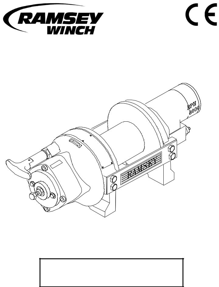
MODEL RPH-8000 PLANETARY WINCH
CAUTION: READ AND UNDERSTAND THIS MANUAL BEFORE INSTALLATION AND OPERATION OF WINCH. SEE WARNINGS!
Ramsey Winch Company
P.O. Box 581510 - Tulsa, OK 74158-1510 USA
Phone: (918) 438-2760 - Fax (918) 438-6688
Visit us at http://www.ramsey.com
OM-914195-0309-C

TABLE OF CONTENTS
INTRODUCTIONS . . . . . . . . . . . . . . . . . . . . . . . . . . . . . . . . . . . . . . . . . . . . . . . . . . . . . . . . . . . . . . . . . . . . . . .3 WARRANTY INFORMATION . . . . . . . . . . . . . . . . . . . . . . . . . . . . . . . . . . . . . . . . . . . . . . . . . . . . . . . . . . . . . . .3 SPECIFICATIONS . . . . . . . . . . . . . . . . . . . . . . . . . . . . . . . . . . . . . . . . . . . . . . . . . . . . . . . . . . . . . . . . . . . . . . .3 WARNINGS . . . . . . . . . . . . . . . . . . . . . . . . . . . . . . . . . . . . . . . . . . . . . . . . . . . . . . . . . . . . . . . . . . . . . . . . . . .3 WINCH MOUNTING . . . . . . . . . . . . . . . . . . . . . . . . . . . . . . . . . . . . . . . . . . . . . . . . . . . . . . . . . . . . . . . . . . . . .4 CABLE INSTALLATION . . . . . . . . . . . . . . . . . . . . . . . . . . . . . . . . . . . . . . . . . . . . . . . . . . . . . . . . . . . . . . . . . . .4 MAINTENANCE . . . . . . . . . . . . . . . . . . . . . . . . . . . . . . . . . . . . . . . . . . . . . . . . . . . . . . . . . . . . . . . . . . . . . . . .5 OPERATION . . . . . . . . . . . . . . . . . . . . . . . . . . . . . . . . . . . . . . . . . . . . . . . . . . . . . . . . . . . . . . . . . . . . . . . . . . .5 ADJUSTING THE BRAKE . . . . . . . . . . . . . . . . . . . . . . . . . . . . . . . . . . . . . . . . . . . . . . . . . . . . . . . . . . . . . . . . .6 HYDRAULIC SYSTEM REQUIREMENTS . . . . . . . . . . . . . . . . . . . . . . . . . . . . . . . . . . . . . . . . . . . . . . . . . . . . . .7 TYPICAL LAYOUT . . . . . . . . . . . . . . . . . . . . . . . . . . . . . . . . . . . . . . . . . . . . . . . . . . . . . . . . . . . . . . . . . . . . . .7 PERFORMANCE CHARTS . . . . . . . . . . . . . . . . . . . . . . . . . . . . . . . . . . . . . . . . . . . . . . . . . . . . . . . . . . . . . . . . .7 TROUBLE SHOOTING GUIDE . . . . . . . . . . . . . . . . . . . . . . . . . . . . . . . . . . . . . . . . . . . . . . . . . . . . . . . . . . . . . .8 OVERHAUL INSTRUCTIONS . . . . . . . . . . . . . . . . . . . . . . . . . . . . . . . . . . . . . . . . . . . . . . . . . . . . . . . . . . . .9-11 DIMENSIONAL DRAWINGS . . . . . . . . . . . . . . . . . . . . . . . . . . . . . . . . . . . . . . . . . . . . . . . . . . . . . . . . . . . .12-13 PARTS LIST AND PARTS DRAWINGS . . . . . . . . . . . . . . . . . . . . . . . . . . . . . . . . . . . . . . . . . . . . . . . . . . . .14-21
LIMITED WARRANTY
RAMSEY WINCH warrants each new RAMSEY Winch to be free from defects in material and workmanship for a period of one (1) year from date of purchase.
The obligation under this warranty, statutory or otherwise, is limited to the replacement or repair at the Manufacturer's factory, or at a point designated by the Manufacturer, of such part that shall appear to the Manufacturer, upon inspection of such part, to have been defective in material or workmanship.
This warranty does not obligate RAMSEY WINCH to bear the cost of labor or transportation charges in connection with the replacement or repair of defective parts, nor shall it apply to a product upon which repair or alterations have been made, unless authorized by Manufacturer, or for equipment misused, neglected or which has not been installed correctly.
RAMSEY WINCH shall in no event be liable for special or consequential damages. RAMSEY WINCH makes no warranty in respect to accessories such as being subject to the warranties of their respective manufacturers.
RAMSEY WINCH, whose policy is one of continuous improvement, reserves the right to improve its products through changes in design or materials, as it may deem desirable without being obligated to incorporate such changes in products of prior manufacture.
If field service at the request of the Buyer is rendered and the fault is found not to be with RAMSEY WINCH's product, the Buyer shall pay the time and expense to the field representative. Bills for service, labor or other expenses that have been incurred by the Buyer without approval or authorization by RAMSEY WINCH will not be accepted.
See warranty card for details.

PLEASE READ THIS MANUAL CAREFULLY
This manual contains useful ideas for obtaining the most efficient operation from your Ramsey Winch, and safety procedures one needs to know before operating a Ramsey Winch. Do not operate this winch until you have carefully read and understand the "WARNING" and "OPERATION" sections of this manual.
WARRANTY INFORMATION
Ramsey Winches are designed and built to exacting specifications. Great care and skill go into every winch we make. If the need should arise, warranty procedure is outlined on the back of your self-addressed postage paid warranty card. Please read and fill out the enclosed warranty card and send it to Ramsey Winch Company. If you have any problems with your winch, please follow instructions for prompt service on all warranty claims. Refer to back page for limited warranty.
SPECIFICATIONS* |
Rated Line Pull |
(lbs.) |
………………………………………………… |
8,000 |
|||
|
|
(Kg.) |
………………………………………………… |
3,620 |
|||
|
Gear Reduction |
…………………………………………………………… |
5.1:1 |
||||
|
Weight (without cable) |
RPH-8000 STD. ……..…....………. 90 lbs. (40.9 Kg) |
|||||
|
|
|
RPH-8000 "Y" ………….………….. 85 lbs. (38.6 Kg) |
||||
|
|
|
|
|
|
|
|
|
LAYER OF CABLE |
1 |
2 |
3 |
4 |
5 |
|
|
|
|
|
|
|
|
|
|
*Rated line pull |
lbs. |
8,000 |
6,800 |
5,900 |
5,200 |
4,700 |
|
per layer |
Kg. |
3,620 |
3,080 |
2,670 |
2,350 |
2,120 |
|
|
|
|
|
|
|
|
|
* Cable Capacity per Layer |
|
|
|
|
||
|
|
|
|
|
|
|
|
|
RPH-8000 (STD. |
ft. |
25 |
55 |
90 |
130 |
170 |
|
DRUM) |
m |
7 |
16 |
27 |
39 |
51 |
|
|
|
|
|
|
|
|
|
RPH-8000 ("Y" |
ft. |
15 |
35 |
60 |
85 |
115 |
|
DRUM) |
m |
4 |
10 |
18 |
25 |
34 |
|
|
|
|
|
|
|
|
|
* Line Speed (at |
FPM |
50 |
58 |
67 |
76 |
84 |
|
15 GPM) |
MPM |
15.2 |
17.6 |
20.3 |
23.1 |
25.5 |
|
|
|
|
|
|
|
|
|
* These specifications are based on recommended wire rope of 3/8" (10mm) |
||||||
|
galvanized aircraft cable, or EIPS cable and a 14.9 cu.in./Rev. motor. |
|
|||||
|
|
|
|
|
|
|
|
NOTE: The rated line pulls shown are for the winch only. Consult the wire rope manufacturer for wire rope ratings.
WARNINGS:
CLUTCH MUST BE FULLY ENGAGED BEFORE STARTING THE WINCH.
DO NOT DISENGAGE CLUTCH UNDER LOAD.
DO NOT LEAVE CLUTCH ENGAGED WHEN WINCH IS NOT IN USE.
STAY OUT FROM UNDER AND AWAY FROM RAISED LOADS.
STAND CLEAR OF CABLE WHILE PULLING. DO NOT TRY TO GUIDE CABLE.
DO NOT EXCEED MAXIMUM LINE PULL RATINGS SHOWN IN TABLE.
DO NOT USE WINCH TO LIFT, SUPPORT, OR OTHERWISE TRANSPORT PERSONNEL.
A MINIMUM OF 5 WRAPS OF CABLE AROUND THE DRUM BARREL IS NECESSARY TO HOLD THE LOAD. CABLE CLAMP (SETSCREW) IS NOT DESIGNED TO HOLD LOAD.
IN CAR CARRIER APPLICATIONS, AFTER PULLING VEHICLE ON CARRIER, BE SURE TO SECURE VEHICLE TO CARRIER BED. DO NOT MAINTAIN LOAD ON WINCH CABLE WHILE TRANSPORTING VEHICLE. DO NOT USE WINCH AS A TIEDOWN.
WHEN PULLING A HEAVY LOAD PLACE A BLANKET, JACKET, OR TARPAULIN OVER THE CABLE FIVE OR SIX FEET FROM THE HOOK.
AVOID CONDITIONS WHERE LOAD SHIFTS OR JERKS OCCUR, AS THEY MAY INDICATE A DANGEROUS SITUATION.
3
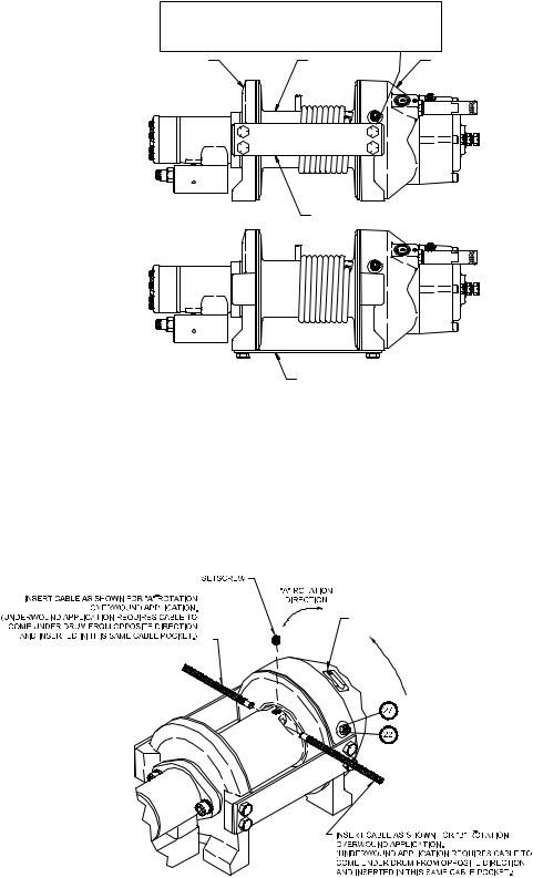
WINCH MOUNTING
ESSENTIAL MOUNTING INSTRUCTIONS TO MAINTAIN ALIGNMENT OF PLANETARY WINCH COMPONENTS:
It is most important that this winch be mounted securely so that the three major sections (the motor end, the cable drum, and the gear housing end) are properly aligned. Excessive bushing wear and difficulty in freespooling are usually symptoms of misalignment.
In the as-installed condition, if the winch is mid-mounted, then at least one tie-plate must be attached to the mounting feet at the bottom of the winch to maintain alignment. If the winch is foot mounted then at least one tie-plate must remain mounted at midpoint of winch to maintain alignment. It is always preferred to used BOTH tie-plates in the final installed configuration.
Angle Mounting Kit, P/N 251006 (for Std. Drum) or 251007 (for “Y” drum), is recommended for maximum ease in mounting the winch. The angle kit will allow the winch to be mounted in upright or midmount applications and will meet the criteria of serving as a solid and true mounting surface.
When mounting the winch with other than the recommended Ramsey Angle Kit, the mounting hole patterns described in the Dimensional drawings on pages 14-15 should be used. The mounting surface must be flat within .015 inch and sufficiently stiff to resist flexing. If a steel plate is used for foot mounting, it should be
.750 inch thick. For this mounting application eight (8) 1/2-13NC x 1-1/2” long grade 5 capscrews with lockwashers will be needed to mount winch. Capscrews should be tightened to 85 ft-lb (115 Nm) torque.
CAUTION: If longer bolts (minimum grade 5) are substituted to mount winch or to mount a roller guide at the side mount pads, bolt length must be such as to allow a maximum of .50 inch thread length engagement in the tapped holes in side of each end bearing. Use of excessive length bolts will damage the winch and prevent freespool of the drum. Torque bolts to 55 ft-lbs. (75 Nm).
MOTOR END |
CABLE DRUM |
GEAR HOUSING END |
FOOT MOUNT |
TIEPLATE AT SIDE LOCATION |
TIEPLATE AT FOOT (BASE) LOCATION
MID MOUNT
NOTE: If angles or a steel plate are used in mounting winch, tie-plates provided with winch are to be attached to the remaining mounting pads, whether they be side or foot.
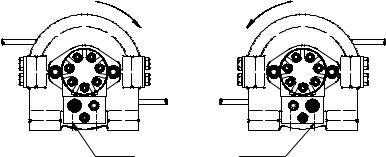
CABLE INSTALLATION
An “A” or “B” decal on the clutch end bearing indicates the spooling direction of the cable. Also, a letter “A” or “B” is stamped in the end bearing on the clutch end indicating rotation direction. If the decal is damaged or unreadable, contact Customer Service for additional instructions to determine proper direction. To reverse the rotation direction, exchange positions of the cartridge and plug shown at right.
1.Unwind cable by rolling it out along the ground to prevent kinking. Securely wrap end of cable, opposite hook, with plastic or similar tape to prevent fraying.
2.Place taped end of cable into hole in cable drum as shown below. Use the 3/8-16NC x 1/2” long hex socket drive setscrew (included with drum assembly item #1) to secure cable to drum.
3.Carefully run winch in the "reel-in" direction. Keeping tension on end of cable, spool all the cable onto the cable drum, taking care to form neatly wrapped layers.
"B" ROTATION DIRECTION
After installing cable, check freespool operation. Disengage clutch and pull on cable at a walking speed. If cable “birdnests”, loosen
jam nut (item #20) and turn nylon setscrew (item #17) clockwise to increase drag on drum. If cable pull is excessive, loosen nylon setscrew by turning counterclockwise. Tighten jam nut when proper setting is obtained.
CAUTION: OVER-TIGHTENING OF JAM NUT MAY STRIP NYLON SETSCREW.
4
CABLE DRUM |
CABLE DRUM |
ROTATION |
ROTATION |
(REEL IN)
RAISE INLET
"A" ROTATION |
"B" ROTATION |
MAINTENANCE
1.Inspect the cable for damage and lubricate frequently. If the cable becomes frayed with broken strands, replace immediately. Cable and hook assembly (100’ long cable) P/N 524118 (“Y” drum) or (150’ long cable) P/N 524119 (STD drum) may be purchased from a Ramsey distributor.
2.Check that the clutch is fully engaging. See OPERATION instructions, above, for the appropriate clutch shifter. FOR MANUAL CLUTCH ONLY: Monthly, disengage clutch, put several drops of oil on the clutch handle shaft and work clutch handle IN and OUT several times to lubricate inside the shifter assembly.
3.Check brake for drift, refer to page 6.
4.Check to see that the drum cable does not overrun (“birdnest”) when freespooling. Refer to page 4 if it does.
5.Replace drum bushings and seals if seals begin to seep grease. Refer to the Overhaul Instructions, pages 9-11. Add additional lubricant, Mobilith SHC 007, to gears and drum bearings if required.
OPERATION
The best way to get acquainted with how your winch operates is to make test runs before you actually use it. Plan your test in advance. Remember, you hear your winch as well as see it operate. Get to recognize the sounds of a light steady pull, a heavy pull, and sounds caused by load jerking or shifting. Avoid conditions where load shifts or jerks occur, as they may indicate a dangerous situation.
The uneven spooling of cable, while pulling the load, is not a problem, unless there is a cable pileup on one end of the drum. If this happens, reverse the winch to relieve the load, and move your anchor point further to the center of the vehicle. After the job is done you can unspool and rewind for a neat lay of the cable.
When pulling a heavy load, place a blanket, jacket, and tarpaulin over the cable about five or six feet behind the hook. In the event of a broken cable, this will slow the snap back of the cable and could prevent serious injury.
The winch clutch allows rapid unspooling of the cable, from the cable drum, for hooking onto the load. The clutch is operated by the clutch shifter lever or air shifter.
WARNING: DO NOT DISENGAGE CLUTCH UNDER LOAD!
MANUAL CLUTCH SHIFTER (Refer to dimensional drawing page 12):
TO DISENGAGE CLUTCH: Run the winch in the reverse (reel out) direction until the load is off the cable. Pull handle out and rotate 90°. With handle in the “DISENGAGED” position, cable may now be free-spooled from the drum.
TO ENGAGE CLUTCH: Pull handle out, rotate 90° and release handle. Run the winch in reverse until the clutch handle snaps fully into the “ENGAGED” position. DO NOT attempt to pull a load unless the handle is fully at the “ENGAGED” position. If manual shift indicator light is present, the green light is lit when clutch is fully “ENGAGED”. DO NOT attempt to pull a load unless the green light is lit. To install light to the vehicle electrical system refer to the Electrical Schematic on page 13.
AIR CYLINDER CLUTCH SHIFTER (Refer to the dimensional drawing page 13):
TO DISENGAGE CLUTCH: Run the winch in the reverse (reel out) direction until load is off the cable. Apply air pressure to the .125-27 NPT port: 80 PSI (min.)-150 PSI (max.). CAUTION: PRESSURE MUST NOT EXCEED 150 PSI.
TO ENGAGE CLUTCH: Remove air pressure from the cylinder (a return spring engages the plunger). Run winch in reverse until the clutch engagement indicator light (green light) is lit. To install light to the vehicle electrical system refer to the Electrical Schematic on page 13.
5
ADJUSTING THE BRAKE
All parts of the oil-cooled automatic safety brake are bathed in oil. When the brake wears to the point that the load begins to drift, the brake can be adjusted as follows:
1.Loosen the lock nut on the adjusting screw (see drawing on Page 10).
2.Increase the brake torque by turning the adjusting screw clockwise. CAUTION: Only 1/4 turn is usually required to adjust the brake. Over-tightening can cause overheating, and damage to the brake parts. Tighten the lock nut after adjustment is completed.
If the brake does not respond to adjustment, then a new flat spring (item #3) and/or brake discs (item #31) may be needed.
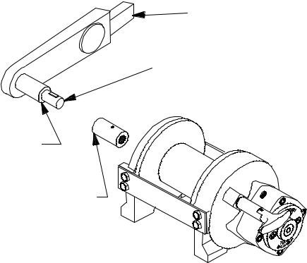
Brake torque can be checked/set as follows: A torque wrench can be equipped with a special adapter to fit the input coupling of the winch. The adapter can be made by welding a 1" diameter straight motor shaft, with 1/4" key, in a 1" hex socket as shown in the following figure.
TORQUE WRENCH
1" DIA. STRAIGHT SHAFT WITH 1/4 " WOODRUFF KEY
1" HEX. SOCKET WELDED TO SHAFT
MOTOR SHAFT COUPLING
This special adapter will fit into the motor shaft coupling. Place coupling onto drum shaft in winch. Turn the torque wrench so that the drum turns in the "CABLE OUT" direction (lowering direction). The torque setting for the brake should be 155 to 160 ftlbs. If the torque wrench does not show the proper torque value, the adjusting screw should be adjusted 1/4 turn (clockwise if torque is low or counter-clockwise if torque is high). Each time the adjusting bolt is turned, check the torque reading. Continue this procedure until the proper torque reading is achieved. Then tighten the lock nut. If proper adjustment cannot be made, follow overhaul instructions on Page 10.
After the brake has been adjusted to the proper torque setting, as described above, disengage clutch. Start vehicle engine and run winch in the "CABLE IN" (raise direction). Allow winch to run in this direction for one minute.
Place your hand on the brake housing. If housing is not hot to the touch then run winch in the reverse direction (cable out) for one minute. Brake housing should begin to heat.
When these conditions exist, proper installation has been made.
6
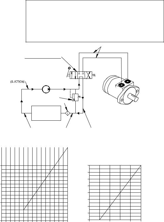
HYDRAULIC SYSTEM REQUIREMENTS
Refer to the performance charts below to properly match your hydraulic system to the winch performance. The charts consist of:
(1)Line Pull first layer (lb.) vs. Working Pressure (PSI)
(2)Line Speed, first layer (FPM) vs. flow (GPM)
|
|
SYSTEM REQUIREMENTS |
|
2500 PSI RELIEF VALVE SETTING |
|
|
|
15 GPM FLOW RATE |
|
DO NOT EXCEED 20 GPM--MOTOR AND WINCH MAY BE DAMAGED |
|
|
10 MICRON NOMINAL FILTRATION |
|
|
1000 PSI MAXIMUM BACK PRESSURE |
|
TYPICAL LAYOUT |
|
HIGH PRESSURE LINES |
|
|
(.5 I.D.) |
|
CONTROL VALVE |
|
|
3 POSITION 4 WAY |
|
|
CYLINDER SPOOL |
|
PUMP INLET LINE |
|
|
(1.00 I.D.) |
PUMP |
|
|
RELIEF VALVE |
|
|
FLUID FILTER |
|
|
FLUID |
HYDRAULIC |
|
WINCH MOTOR |
|
|
RESERVOIR |
|
|
|
|
|
LOW PRESSURE LINES |
LOW PRESSURE LINES |
|
|
(.75 I.D.) |
(.75 I.D.) |
PERFORMANCE CHARTS |
|
||
50 |
|
|
|
|
|
|
|
|
|
|
|
|
|
|
|
|
|
|
|
|
|
|
|
LINE SPEED-FIRST LAYER (FPM)
40 |
|
|
|
|
8000 |
|
|
|
|
|
|
|
|
|
(LB) |
7000 |
|
|
|
|
|
|
|
|
|
6000 |
|
|
|
|
|
|
30 |
|
|
|
LAYER |
5000 |
|
|
|
|
|
|
|
|
|
|
|
|
|
|
||
|
|
|
|
|
|
|
|
|
|
|
|
|
|
|
FIRST-PULL |
4000 |
|
|
|
|
|
|
|
|
|
3000 |
|
|
|
|
|
|
|
|
|
|
|
|
|
|
|
|
|
20 |
|
|
|
|
|
|
|
|
|
|
|
|
|
|
LINE |
2000 |
|
|
|
|
|
|
|
|
|
1000 |
|
|
|
|
|
|
10 |
|
|
|
|
0 |
|
|
|
|
|
|
|
|
|
0 |
500 |
1000 |
1500 |
2000 |
2500 |
|
0 |
5 |
10 |
15 |
|
||||||
FLOW (GPM) |
|
|
|
|
WORKING PRESSURE (PSI) AT 15 GPM |
|||||
BASED ON 15.5 CU. IN. MOTOR
7

TROUBLESHOOTING GUIDE
CONDITIONS |
POSSIBLE CAUSE |
CORRECTION/ACTION |
|
|
|
DRUM WILL NOT ROTATE |
Winch not mounted squarely, causing end bearing |
Check mounting. Refer to Winch Mounting, page 4. |
AT NO LOAD |
to bind up |
|
|
Brake damaged |
Inspect and replace brake |
|
Gears damaged |
Inspect and replace damaged gears |
|
|
|
DRUM WILL NOT ROTATE |
Winch not mounted squarely, causing end bearing |
Check mounting. Refer to Winch Mounting, page 4. |
UNDER LOAD |
to bind up |
|
|
Load greater than rated capacity of winch |
Refer to Specifications page 3 for line pull rating. |
|
Low hydraulic system pressure |
Check pressure. Refer to Hydraulic Systems per- |
|
|
formance charts page 7. |
|
|
|
WINCH RUNS TOO SLOW |
Low hydraulic system flow rate |
Check flow rate. Refer to Systerm Requirements and |
|
|
Typical Layout page 7. |
|
Motor worn out |
Replace motor |
DRUM WILL NOT |
Clutch not disengaged. Check Adjustment of Manual |
FREESPOOL |
Shifter, page 9. |
|
Winch not mounted squarely, causing end bearing |
|
to bind up |
|
Side mounted bolts too long, causing binding of ring |
|
gear (Item #15, page 14). |
Check Operation, page 5.
Check mounting. Refer to Winch Mounting, page 4.
Check bolt length. Bolt thread MUST NOT engage threaded holes in sides of end bearing more than the
.50 inch thread depth in the end bearing.
LOAD DRIFTS |
Brake needs adjusting |
Adjust brake. see Page 6. |
|
|
|
CABLE BIRDNESTS WHEN |
Drag screw improperly adjusted |
Adjust nylon drag screw. Refer to Cable Installation, |
CLUTCH IS DISENGAGED |
|
page 4. |
|
|
|
EXCESSIVE NOISE |
Hydraulic system flow too high |
Check flow rate. Refer to Typical Layout page 7. |
|
Brake Torque too high |
Reduce torque. Refer to page 6. |
|
Brake oil level low. |
Check oil level, add oil if necessary. |
|
Drum in bind, winch not mounted squarely |
Check mounting. Refer to Winch Mounting, page 4. |
|
|
|
DRUM CHATTERS IN |
Low hydraulic system flow rate |
Check flow rate. Refer to Typical Layout page 7. |
“REEL IN” DIRECTION |
|
|
|
Low hydraulic system relief pressure setting |
Check relief valve setting. |
|
|
|
8
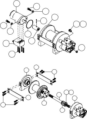
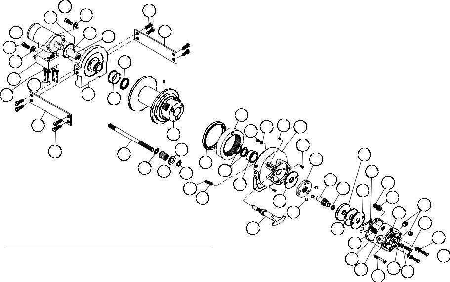
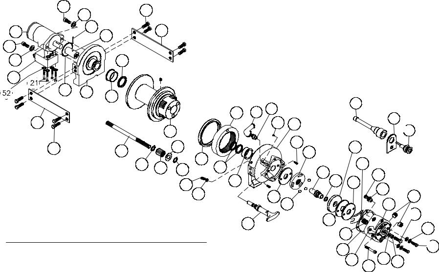
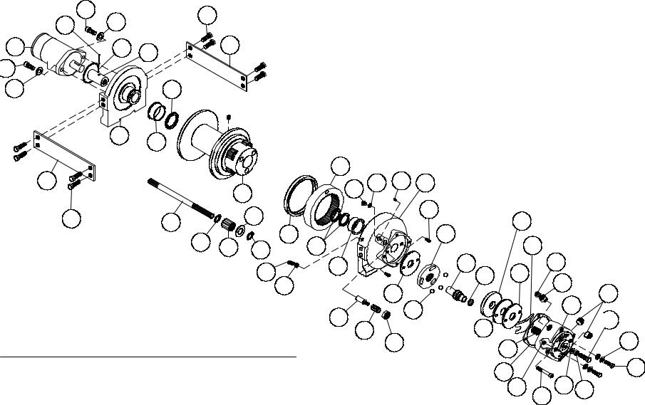
INSTRUCTIONS FOR OVERHAUL RPH-8000 SERIES WINCH
Take note of mounting configurations for proper mounting of parts during re-assembly. Replace all gaskets, o-rings, and seals during re-assembly.
35
Remove breather plug and reducer (item #34 and #39) from |
|
|
winch. Drain oil from winch by removing plug (item #40). |
|
|
Remove motor (item #35), coupling (item #31) from winch |
|
|
by unscrewing capscrews (item #24). If coupling is being |
24 |
|
replaced, be sure pin (item #41) is installed. Tap motor lightly |
||
to disengage. Replace all o-rings and seals with new ones |
30 |
|
during re-assembly (order kit #246042). If necessary, remove |
||
|
||
valve (item #49) from motor by removing lockwashers (item |
|
|
#52) and capscrews (item #21). |
49 |
|
|
21 |
24
30
7
41
34 39
38
31
40
|
7 |
13 |
|
Remove tie plates (item #13) from end bearings (items #7 & |
18 |
||
|
|||
|
|
||
#8) by unscrewing capscrews (item #18), as shown. Slide |
|
|
|
motor end bearing (item #7) from drum (item #1) and drum |
|
|
|
from gear housing end bearing (item #8). Remove input shaft |
|
|
|
(item #12) from end bearing. Inspect teeth of gear (item #5) |
|
50 47 |
|
for signs of wear. If necessary replace gear by removing snap |
|
||
13 |
12 |
||
ring (item #47) and thrust washer (item #50). Slide new |
8 |
||
gear over splines of shaft and against snap ring on shaft. Re- |
|
1 |
|
install thrust washer and place snap ring into groove of shaft. 18 |
|
|
|
|
|
5 |
9
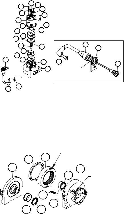
Remove brake housing (item #9) from end bearing (item #8) by unscrewing (4) capscrews (item #23). Remove plate (item #12) and light assembly, if present. Remove gasket (item #33), coil spring (item #48), flat spring (item 3), retainer plate (item #11), composition brake discs (item #32) and cam plate (item #4). Remove hub (item #10) with plug (item #42) – which is press-fitted in the hub I.D. (Inside Diameter). Inspect the seal (item #37), inside of gear housing bore, and replace if necessary.
Inspect brake discs. Discs are 1/4" thick when new, replace if thinner than .200 inch thick or if surfaces are glazed or burnt. Inspect the flat ground surfaces of the cam plate and retainer plate for glazing, warpage or other damage. Glazing can be removed by scraping carefully. Inspect flat spring. It should be bowed at least 1/8". Replace spring if bowed less than 1/8".
|
|
19 |
28 |
|
17 |
|
|
|
|
44 |
|
|
|
|
|
|
29 |
|
23 |
|
|
|
|
9 |
|
|
|
|
33 |
|
48 |
|
|
|
|
11 |
|
|
3 |
|
|
|
32
 4
4
51 |
42 |
46 |
|
12 |
|||
|
|||
|
|
||
|
14 |
|
 10
10
12 32
37 45
2
8 |
NUT |
CLUTCH ENGAGEMENT INDICATOR
LIGHT ASSEMBLY
52
45
Replace all worm or damaged parts as needed. Re-assemble all parts as shown. Be sure balls are secure between cam plate and hub.
Install brake housing, making sure that ends of capscrews (item #17) go through notches in end of flat springs and holes in the retainer plate. Secure brake housing and plate (item #12), if present, to end bearing using capscrews (item #23). Tighten capscrews to 30-40 ft-lbs.
INDICATOR LIGHT ASSEMBLY
If light is not functioning, remove light (item #2) and apply 12V DC (+) to test. If necessary, remove the switch (item #52). The terminals are normally closed. With ball depressed, the switch should be open. Replace light and/or switch, as needed.
Remove o-ring (item #36) and bushing (item |
|
SLOT IN RING GEAR |
|
#15) from motor end bearing (item #7). Press |
|
||
45 |
6 |
|
|
new bushing onto end bearing and dip o-ring in |
|
||
|
|
||
|
|
|
|
oil and seat into groove of end bearing. Remove |
7 |
|
8 |
seal (item #45) from gear housing end bearing |
|
||
|
|
||
|
16 |
|
|
(item #8). Loosen nut (item #27) and remove |
|
CLUTCH |
|
nylon setscrew (item #22) and remove ring |
|
|
SHIFTER HOLE |
gear (item #6) from gear housing end bearing, |
|
|
|
if necessary. Remove bushing (item #16) from |
|
22 |
|
gear housing end bearing (item #8). Press new |
|
|
|
bushing (item #16) into place in end bearing. |
|
27 |
|
Install ring gear and nylon setscrew and nut. |
|
|
|
15 |
36 |
|
|
Ring gear must be fully seated in gear housing |
|
||
|
|
|
|
end bearing (item #8) and slot in ring gear
must NOT be aligned with clutch shifter hole. Install new seal in gear housing end bearing, with sharp edge of seal outward.
Generously apply grease (MOBILITH SHC 007) to teeth of ring gear (item #6), teeth of planet gears in drum (item #1) and to bushing in end bearings (items #7 & #8). Apply grease to teeth of gear (item #5) and to splines of shaft (item #12). Place splined end of shaft into splines of hub in brake housing end bearing (item #8). Place drum over shaft and rotate drum to engage planet gears with output gear on shaft and ring gear in end bearing.
Assemble end bearing to drum assembly and use tie plates (item #13) and capscrews (item #18) to hold both end bearings together. Tighten capscrews to 55 ft-lbs. (75 Nm.).
10
If necessary, remove and replace the shifter assembly (manual, item #2, or air-cylinder, item #3), as follows:
MANUAL CLUTCH SHIFTER ASSEMBLY
Remove by loosening setscrew (item |
|
|
|
|
#25), jam nut and unscrewing clutch |
|
|
|
HANDLE (HORIZONTAL) |
shifter. Be sure slot in ring gear is not |
|
|
|
|
aligned with clutch shifter hole. |
13 |
7/16 |
+0 |
|
Rotate drum, if necessary, to insure |
-1/16 |
|
||
7 |
|
|
|
|
hole and slot are not aligned. Re-install |
18 |
|
CYLINDER |
|
|
|
|
||
|
|
|
|
|
clutch shifter with plunger, jam nut and |
|
|
|
|
handle positioned in cylinder housing, |
|
|
MANUAL CLUTCH ADJUSTMENT |
|
as shown. Thread assembly (with |
|
|
||
|
|
|
|
|
handle engaged in cylinder slot) into |
|
|
|
|
the end bearing. Pull drum toward the |
12 |
|
25 |
|
brake housing end bearing to remove |
|
|
||
13 |
|
8 |
|
|
play. |
1 |
|
|
PLUNGER ASSEMBLY |
Hold drum in the position and continue |
18 |
|
|
|
|
5 |
|
JAM NUT |
|
threading the shifter assembly in until |
PLANET GEARS |
|
|
|
the gap between the end of the handle |
|
|
|
SETSCREW |
and cylinder is 7/16 +0 -1/18 inch |
|
|
|
BLOCKED CLUTCH |
PLUNGER |
|
2 |
MANUAL CLUTCH |
|
and handle is in the horizontal posi- |
|
|||
49 |
|
|
SHIFTER |
|
tion, as shown below. NOTE: This gap |
|
|
|
|
will vary with drum endplay. With the |
AIR-CYLINDER |
|
JAM NUT |
|
drum pulled against the gear housing, |
|
3 |
|
|
CLUTCH SHIFTER |
|
|
||
the gap should be 7/16 inch. Lightly |
|
|
|
|
tighten jam nut. |
|
|
|
|
Rotate drum until handle snaps fully into the engaged position. Pull handle out and rotate 90º. Verify that drum can be rotated freely (at least one full revolution) with clutch shifter at DISENGAGED position. Securely tighten jam nut while holding the handle.
Tighten setscrew securely. Re-check clutch operation as described on Page 5.
AIR CYLINDER SHIFTER ASSEMBLY
Remove by loosening setscrew (item #25), jam nut and unscrewing clutch shifter. To reinstall, thread air cylinder into housing. Install one or two shims (item #49) under cylinder head, if needed, to orient air cylinder port for pneumatic connections. Tighten setscrew. Refer to Page 5 and check for proper operation of the clutch.
BLOCKED CLUTCH
Insert plunger assembly into gear housing bore so it engages into ring gear slot. Pull drum flange toward gear housing and thread setscrew into housing until it bottoms out and drum starts to move. Back setscrew out 1/2 turn and lock in place with jam nut.
Before installing motor, check brake adjustment (refer to Page 7, ADJUSTING THE BRAKE).
Place splined end of coupling (item #31), with spirol pin (item |
|
#41) installed, inside of motor end bearing housing (item #7) |
35 |
and slide over splines on end of input shaft. Place o-ring (item #38) around motor pilot. Mount motor (item #35) to end bearing by aligning key on motor shaft with keyway in coupling. Be sure that motor mounts flush to end bearing and that
o-ring is set securely in place between motor and end bearing. 24 Secure motor to end bearing using two capscrews and lock-
washers (items #24 & #30). Tighten capscrews to 49 ft-lbs. |
30 |
|
|
(66 Nm.). Thread plug (item #40) into bottom of brake hous- |
|
ing. Permatex can be added to threads of plug to help in seal- |
|
ing. |
|
38
31
24
30
KEY
7
41
34 39
40
OIL LEVEL HOLE
40
Pour mixture of 1/2 pint (8 ounces) of Mobilfluid 424, Phillips HG Fluid, Texaco TDH, Shell Oil Company Donax TD high per-
formance tractor transmission fluid, or equivalent, and 1/4 ounce of an oil additive (available from the factory) into oil level hole. Oil level should be kept at oil level hole (plus or minus 1/8"). Thread plug (item #40) into oil level hole. Insert reducer (item 339) into hole in top of brake housing and breather plug (item #34) into reducer. Tighten plugs and reducer securely.
11
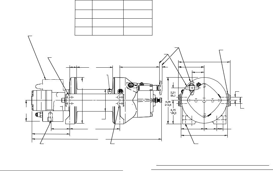
DIM. |
RPH-8,000-S |
RPH-8,000-Y |
|
LETTER |
("STD." DRUM) |
("Y" DRUM) |
|
A |
9.75 |
6.50 |
|
247,6 |
165,1. |
||
*B |
12.25 |
9.00 |
|
311,1 |
228,6. |
||
C |
26.53 |
23.28 |
|
673,9 |
591.3 |
||
|
MOTOR/COUNTERBALANCE
VALVE MAY BE MOUNTED
WITH PORTS UP
|
|
CLUTCH DISENGAGED POSITION |
|
|
|
|
|
|
|
|
|
|
FOR SIDE MOUNT |
|
|||
|
|
|
|
|
|
|
|
|
|
|
|
|
|
|
|||
.500-13UNC X .75 (INCHES) DEEP |
CLUTCH ENGAGED POSITION |
|
|
|
|
|
|
|
|
|
|
|
INSTALLATIONS, MOVE |
||||
|
|
|
|
|
|
|
|
|
|
|
TIEPLATES TO FEET. |
|
|||||
TAPPED HOLE (TYP. 2 PLACES EACH |
|
|
|
|
|
|
|
|
|
|
|
|
|
||||
|
|
|
|
|
|
9.36 |
|
|
|
|
|
|
|||||
SIDE OF MOTOR END BEARING) |
|
|
|
|
|
|
|
|
|
|
|
|
|||||
1.25 |
A |
7.17 |
.50 |
4.68 |
|
|
237.7 |
|
|
|
|
|
|
||||
|
|
|
|
|
|
|
|
|
|
|
|
|
|||||
31.8 |
182.1 |
12.7 |
118.9 |
|
|
|
|
|
|
|
|
|
|
|
|
|
|
.50 IN. (12,7MM) DIA. |
|
|
2.21 |
|
|
|
|
|
|
|
|
|
|
|
|||
|
|
56.1 |
|
|
|
|
|
|
|
|
|
|
|
||||
|
CABLE HOLE |
|
|
|
|
|
|
|
|
|
|
|
|
|
|||
|
|
|
|
|
|
|
|
|
|
|
|
|
|
|
|
|
|
8.25 |
FLANGE DIA. |
|
|
|
|
|
|
|
|
|
|
|
|
|
|
|
|
209.6 |
|
|
|
|
|
|
|
|
|
|
|
|
|
|
* |
|
|
|
|
|
|
|
|
|
|
|
E Y |
IN |
|
|
|
||||
12 |
|
|
|
|
|
|
S |
|
|
.56 |
|
|
|||||
|
|
|
|
A |
M |
|
|
W |
|
|
|
(TYP.) |
|||||
|
|
|
R |
|
|
A |
|
|
C |
|
14.2 |
||||||
|
|
|
C |
O |
M P |
Y |
|
|
|
||||||||
|
|
|
|
|
|
|
|
|
|
N |
H |
|
|
|
|
||
3.79 |
|
|
|
|
|
TU |
LS A |
, |
A |
|
*1.12 |
(TYP.) |
|||||
|
|
|
O |
|
|
|
M |
|
28.4 |
||||||||
|
|
|
|
|
K |
|
|
|
|
|
|||||||
|
|
|
|
|
|
L |
|
|
|
|
|||||||
96,3 |
|
|
|
|
|
|
|
|
AHO |
|
|
|
|||||
3.94 |
|
|
|
|
|
|
|
|
|
|
|
|
|
|
|
|
|
|
|
|
|
|
|
|
|
|
|
|
|
|
|
|
|
|
|
|
100.0 |
|
|
|
|
|
|
|
|
|
|
|
|
|
|
|
|
BARREL DIA. |
|
|
|
|
|
|
|
|
|
|
|
|
|
|
|
|
|
3.39 |
B |
|
|
4.19 |
|
|
|
|
|
|
|
*2.25 |
*1.12 |
(TYP.) |
|
|
|
86.1 |
|
|
106.4 |
|
|
|
|
|
|
|
57.2 |
28.4 |
|
|
|||
6.75 |
|
|
|
|
8.38 |
(TYP.) |
|
|
|
|
|||||||
171.5 |
C |
|
|
|
|
|
|
|
|||||||||
|
|
212.9 |
|
|
|
|
|
|
|
||||||||
|
|
|
|
|
|
|
|
|
|
||||||||
|
|
|
|
|
|
|
|
|
|
|
|
|
|
|
|
|
|
.875-14 SAE PORT |
.500-13UNC X .50 (INCHES) DEEP |
(TYP. 2 PLACES) |
TAPPED HOLE (TYP. 2 PLACES EACH |
|
SIDE OF GEAR HOUSING END BEARING) |
.500-13UNC X .75 (INCHES) DEEP TAPPED HOLE (TYP. 4 PLACES EACH END BEARING)
MODEL RPH 8,000
DIMENSIONS SHOWN ARE INCHES OVER MILLIMETERS
WINCH MOUNTING CAPSCREWS MUST MEET OR EXCEED SAE GRADE 5 SPECIFICATION
WITH MANUAL CLUTCH SHIFTER
*NOTE: THESE HOLE LOCATIONS MUST BE HELD WITHIN ±.03" (0.8 MM) OF
TRUE POSITION. RECOMMENDED MOUNTING HOLE DIAMETER IS .53" (13.5 MM).
13
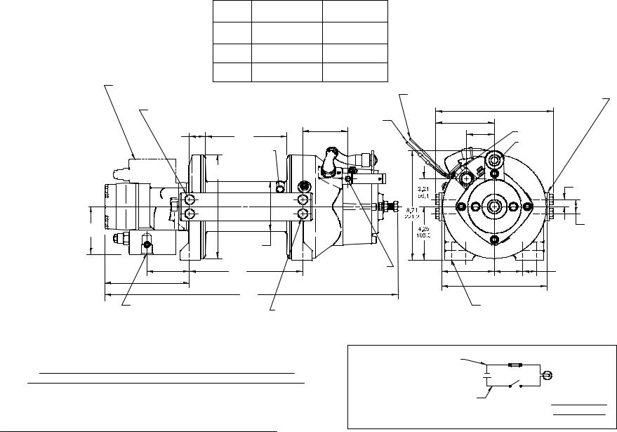
DIM. |
RPH-8,000-S |
RPH-8,000-Y |
|
LETTER |
("STD." DRUM) |
("Y" DRUM) |
|
A |
9.75 |
6.50 |
|
247,6 |
165,.1 |
||
* B |
12.25 |
9.00 |
|
311,1 |
228,.6 |
||
|
|||
C |
26.53 |
23.28 |
|
673,9 |
591,3 |
MOTOR/COUNTERBALANCE
VALVE MAY BE MOUNTED
WITH PORTS UP.
.500-13UNC X .75 (INCHES) DEEP TAPPED HOLE (TYP. 2 PLACES EACH SIDE OF MOTOR END BEARING)
1.25 |
A |
31,8 |
.50 IN. (12,7) DIA. CABLE HOLE
8.25
209,6 FLANGE DIA.
3.79
96,3
3.94
100,0 BARREL DIA.
ATTACH TO GROUND (SEE ELECTRICAL SCHEMATIC)
5.84
148,3
ATTACH TO 12V DC (+)
(SEE ELECTRICAL SCHEMATIC)
|
|
|
9.36 |
|
||||
4.68 |
|
|
237,7 |
|
||||
|
|
|
|
|
|
|
|
|
118,9 |
|
|
|
|
|
|
|
|
2.21 |
|
|
|
|
|
|
||
56,1 |
|
|
|
|
|
|
||
|
|
|
TC |
H |
EN |
|
|
|
|
|
|
|
G |
|
|||
|
|
|
|
|
|
A |
|
|
|
|
|
U |
|
|
|
G |
|
|
|
|
L |
|
|
|
E |
|
|
|
|
C |
|
|
|
D |
|
|
|
|
* |
|
|
|
* |
|
|
|
|
W |
|
|
L |
IT |
|
|
|
|
H |
|
|
|||
|
|
|
|
EN |
|
|
||
|
|
M |
S |
E Y |
|
IN |
||
|
|
|
A |
C |
||||
|
A |
|
|
|
|
W |
|
|
R |
|
O |
M P |
Y |
||||
|
|
C |
|
|
|
N |
H |
|
|
|
|
|
|
|
|
|
|
FOR SIDE MOUNT INSTALLATIONS, MOVE TIEPLATES TO FEET.
SWITCH
INDICATOR
LIGHT
*
14,2.56 (TYP.)
TU |
LS A |
, |
A |
*1.12 |
(TYP.) |
|
O |
|
M |
28,4 |
|||
K |
|
|
||||
L |
|
|
||||
|
AHO |
|
|
|||
3.39
86,1
6.75
171.5
.875-14 SAE PORT (TYP. 2 PLACES)
** CAUTION: PRESSURE MUST NOT EXCEED 150 PSI.
B
C
.125-27NPT PORT
(CONNECT 80 TO 150 PSI** PRESSURE LINE TO DISENGAGE
CLUTCH.)
.500-13UNC X .50 (INCHES) DEEP TAPPED HOLE (TYP. 2 PLACES EACH SIDE OF GEAR HOUSING END BEARING)
4.19 |
*2.25 |
*1.12 |
(TYP.) |
106,4 |
57,2 |
28,4 |
|
|
8.38 (TYP.) |
|
|
212,9
.500-13UNC X .75 (INCHES) DEEP TAPPED HOLE (TYP. 4 PLACES EACH END BEARING)
DIMENSIONS SHOWN ARE INCHES OVER MILLIMETERS
WINCH MOUNTING CAPSCREWS MUST MEET OR EXCEED SAE GRADE 5 SPECIFICATION
*NOTE: THESE HOLE LOCATIONS MUST BE HELD WITHIN ±.03" (0.8 MM) OF TRUE POSITION. RECOMMENDED MOUNTING HOLE DIAMETER IS .53" (13.5 MM).
MODEL RPH 8,000
ATTACH TO GROUND (16 GA. |
BUTT |
WIRE SUPPLIED BY CUSTOMER) |
CONNECTOR |
|
_ |
12V BATTERY |
|
|
+ |
|
SWITCH |
ATTACH TO PTO INDICATOR SWITCH TO
RECEIVE 12V DC WHEN PTO IS ENGAGED.
NOTE: LIGHT SHOULD BE "ON" WHEN CLUTCH IS ENGAGED AND "OFF" WHEN CLUTCH IS DISENGAGED.
INDICATOR LIGHT (ON WHEN CLUTCH IS ENGAGED)
ELECTRICAL SCHEMATIC
WITH AIR-CYLINDER CLUTCH SHIFTER
14
|
|
24 |
18 |
|
41 |
30 |
|
|
|
||
|
|
|
|
35 |
|
38 |
13 |
|
|
|
31 |
24 |
|
|
|
30 |
|
|
36 |
49 |
21 |
|
|
|
|
|
|
52 |
|
7 |
15 |
|
|
|
6
13 |
|
|
|
43 |
46 |
25 |
8 |
|
|
|
|
1 |
|
|
|
|
|
|
|
|
|
|
|
|
|
|
18 |
|
|
50 |
|
|
|
20 |
|
12 |
|
|
|
|
|
4 |
||
|
|
|
|
|
|
|||
|
|
|
|
|
|
10 |
||
|
|
|
|
45 |
|
|
|
|
|
47 |
|
|
|
|
|
|
|
|
5 |
47 |
37 |
|
|
|
3 |
|
|
|
|
|
|
||||
|
|
|
|
|
|
51 |
|
|
|
|
|
|
17 |
|
|
|
|
|
|
|
22 |
|
|
42 |
11 |
|
|
|
|
|
|
|
|||
|
|
|
|
|
|
|
|
|
|
|
|
|
27 |
|
32 |
|
|
|
|
|
|
|
|
|
|
|
|
|
|
|
|
|
|
14 |
|
MODEL RPH 8,000 |
2 |
|
|
32 |
|
|||
|
|
|
|
48 |
||||
WITH MANUAL CLUTCH SHIFTER |
|
|
|
|
33 |
|||
|
|
|
|
|
|
|
|
26 |
23
34
39
40
9
19
44 28
29
17
PARTS LIST - MANUAL SHIFT
15
Item No. |
Quantity |
Part No. |
Description |
|
Item No. |
Quantity |
Part No. |
Description |
1 |
1 |
234165 |
DRUM Assembly "Y" |
|
26 |
2 |
418034 |
NUT 3/8-16NC HEX.REG. |
|
1 |
234166 |
DRUM Assembly "Standard" |
|
27 |
1 |
418036 |
NUT 3/8-16NC HEX. JAM |
2 |
1 |
276048 |
SHIFTER Assembly |
|
28 |
1 |
418061 |
NUT-1/2-13NC HEX. JAM |
3 |
1 |
306035 |
SPRING-FLAT, BRAKE |
|
29 |
4 |
418184 |
WASHER-3/8 ID X 5/8 OD X 1/16 FLAT ALUM |
4 |
1 |
314017 |
CAM PLATE-”A” ROTATION |
|
30 |
2 |
418218 |
LOCKWASHER-1/2 I.D. MED. SECT. |
|
1 |
314018 |
CAM PLATE-”B” ROTATION |
|
31 |
1 |
431014 |
COUPLING-HYD. MOTOR |
5 |
1 |
334174 |
GEAR-OUTPUT, SUN |
|
32 |
2 |
438018 |
PLATE-BRAKE |
6 |
1 |
444084 |
GEAR-RING |
|
33 |
1 |
442212 |
GASKET-Brake Housing |
7 |
1 |
338326 |
END BEARING-MOTOR |
|
34 |
1 |
456008 |
RELIEF FITTING |
8 |
1 |
338327 |
HOUSING-GEAR, END BEARING |
|
35 |
1 |
458074 |
MOTOR-HYD. (FOR MODEL WITH COUNTERBALANCE VALVE) |
9 |
1 |
338328 |
HOUSING-BRAKE |
|
|
1 |
458075 |
MOTOR-HYD. (FOR MODEL WITHOUT COUNTERBALANCE VALVE) |
10 |
1 |
314019 |
HUB PLATE |
|
36 |
1 |
462046 |
O-RING |
11 |
1 |
352021 |
RETAINER PLATE |
|
37 |
2 |
462047 |
QUAD-RING |
12 |
1 |
357489 |
SHAFT-INPUT "Y" |
|
38 |
1 |
462048 |
O-RING |
|
1 |
357490 |
SHAFT-INPUT " Standard" |
|
39 |
1 |
468002 |
REDUCER |
13 |
2 |
395163 |
TIE PLATE "Y" |
|
40 |
2 |
468018 |
PIPE PLUG |
|
2 |
395172 |
TIE PLATE " Standard" |
|
41 |
1 |
470033 |
SPIROL PIN |
14 |
3 |
400007 |
BALL |
|
42 |
1 |
472051 |
PLUG |
15 |
1 |
412084 |
BUSHING-DRUM, MOTOR END |
|
43 |
1 |
472052 |
PLUG |
16 |
1 |
412085 |
BUSHING-DRUM, GEAR |
|
44 |
1 |
486076 |
SEAL |
17 |
2 |
414273 |
BOLT-3/8-16NC X 1-3/4" LG, Hexhead, GR. 5 |
|
45 |
1 |
486080 |
SEAL-GEAR HSG. |
18 |
8 |
414581 |
CAPSCREW-1/2-13NC X 3/4" LG. Hexhead, GR. 5, zinc |
|
46 |
1 |
518037 |
SHIM |
19 |
1 |
414622 |
BOLT-1/2-13NC X 2-1/4" LG, Hexhead, GR. 5, ALL-THD. |
|
47 |
2 |
490003 |
SNAP RING |
20 |
2 |
414836 |
CAPSCREW-1/4-20NC X 1/2" LG, Hex Socket head |
|
48 |
1 |
494010 |
SPRING |
21 |
4 |
414159 |
CAPSCREW-5/16-18NC X 2-1/2" LG, HexheadGR5 zinc |
|
49 |
1 |
516008 |
VALVE-COUNTERBALANCE ("A" ROTATION) |
22 |
1 |
414926 |
SETSCREW-3/8-16NC X 1" LG, Sockethead, NYLON |
|
|
1 |
516009 |
VALVE-COUNTERBALANCE ("B" ROTATION) |
23 |
4 |
414934 |
CAPSCREW-3/8-16NC X 2-3/4" LG, Hex sockethead |
|
50 |
1 |
518047 |
WASHER-THRUST |
24 |
2 |
414952 |
CAPSCREW-1/2-13NC X 1-1/2" LG, Hex sockethead |
|
51 |
1 |
340077 |
BRAKE SHAFT |
25 |
1 |
416016 |
SETSCREW-1/4-20NC X 1/4" LG Hex sockethead. |
|
52 |
4 |
418163 |
LOCKWASHER - 5/16 MED SECT zinc |
16
|
26 |
|
20 |
|
|
|
|
|
|
|
|
|
32 |
|
|
|
|
|
|
|
|
|
|
|
|
|
|
|
|
|
|
|
37 |
|
43 |
|
15 |
|
|
|
|
|
|
|
|
33 |
|
|
|
|
|
|
||
|
|
|
|
|
|
|
|
|
|
|
26 |
|
|
|
|
|
|
|
|
|
|
32 |
|
|
38 |
|
|
|
|
|
|
|
52 |
|
|
|
|
|
|
|
|
|
|
|
40 |
8 |
17 |
|
|
|
|
|
|
|
|
|
|
|
|
|
|
|
|
||
|
|
|
|
|
|
|
|
|
46 |
|
|
|
|
|
|
|
|
|
51 |
|
|
|
|
|
|
|
|
7 |
45 |
|
|
|
|
|
|
|
|
|
|
|
|
||
15 |
|
|
|
|
|
|
|
27 |
9 |
|
|
|
|
|
|
1 |
|
|
|
|
|
20 |
|
|
|
|
54 |
|
|
|
22 |
5 |
|
|
14 |
|
|
|
|
11 |
|||
|
|
|
|
48 |
|
|
|
|
||
|
|
|
50 |
|
|
|
|
|
4 |
|
|
|
|
6 |
50 |
39 |
|
|
|
||
|
|
|
|
|
|
54 |
|
|||
|
|
|
|
|
|
|
|
|
||
|
|
|
|
|
|
|
|
|
|
|
|
|
|
|
|
24 |
18 |
|
|
44 |
13 |
|
|
|
|
|
|
|
|
|
|
|
|
|
|
|
|
29 |
|
|
34 |
|
|
|
|
|
|
|
|
|
|
|
|
|
|
|
|
|
|
|
|
|
|
16 |
|
MODEL RPH 8,000 |
|
3 |
|
34 |
|
|||||
|
|
|
|
|||||||
|
|
|
|
50 |
||||||
|
|
|
|
|
|
|
|
|
|
|
WITH MANUAL CLUTCH SHIFTER AND |
|
|
|
|
35 |
|||||
CLUTCH ENGAGEMENT INDICATOR LIGHT |
|
|
|
|
28 |
|||||
|
|
|
|
|
||||||
12
 2
2
36
41
42
10
 21
21
47 30
25
31
 19
19
PARTS LIST - MANUAL SHIFT AND CLUTCH ENGAGEMENT LIGHT
17
Item No. |
Quantity |
Part No. |
Description |
|
Item No. |
Quantity |
Part No. |
Description |
1 |
1 |
234165 |
DRUM ASSEMBLY "Y" |
|
27 |
1 |
416016 |
SETSCREW-1/4-20NC X 1/4" LG HX. sockethead |
|
1 |
234166 |
DRUM ASSEMBLY "STANDARD" |
|
28 |
2 |
418034 |
NUT 3/8-16NC HEX.REG. |
2 |
1 |
236020 |
LIGHT ASSEMBLY |
|
29 |
1 |
418036 |
NUT 3/8-16NC HEX. JAM |
3 |
1 |
276048 |
SHIFTER ASSEMBLY |
|
30 |
1 |
418061 |
NUT-1/2-13NC HEX. JAM |
4 |
1 |
306035 |
SPRING-FLAT, BRAKE |
|
31 |
4 |
418184 |
WASHER-3/8 I.D. X 5/8 O.D. X 1/16 FLAT ALUM |
5 |
1 |
314017 |
CAM PLATE-"A" ROTATION |
|
32 |
2 |
418218 |
LOCKWASHER-1/2 I.D. MED. SECT. |
|
1 |
314018 |
CAM PLATE-"B" ROTATION |
|
33 |
1 |
431014 |
COUPLING-HYD. MOTOR |
6 |
1 |
334174 |
GEAR-OUTPUT, SUN |
|
34 |
2 |
438018 |
PLATE-BRAKE |
7 |
1 |
444084 |
GEAR-RING |
|
35 |
1 |
442212 |
GASKET-Brake Housing |
8 |
1 |
338326 |
END BEARING-MOTOR |
|
36 |
1 |
456008 |
RELIEF FITTING |
9 |
1 |
338327 |
HOUSING-GEAR, END BEARING |
|
37 |
1 |
458074 |
MOTOR-HYD. (FOR MODEL WITH COUNTERBALANCE VALVE) |
10 |
1 |
338328 |
HOUSING-BRAKE |
|
|
1 |
458075 |
MOTOR-HYD. (FOR MODEL WITHOUT COUNTERBALANCE VALVE) |
11 |
1 |
314019 |
HUB PLATE |
|
38 |
1 |
462046 |
O-RING |
12 |
1 |
350598 |
PLATE-LIGHT Mounting |
|
39 |
2 |
462047 |
QUAD-RING |
13 |
1 |
352021 |
RETAINER PLATE |
|
40 |
1 |
462048 |
O-RING |
14 |
1 |
357489 |
SHAFT-INPUT "Y" |
|
41 |
1 |
468002 |
REDUCER |
|
1 |
357490 |
SHAFT-INPUT "STANDARD" |
|
42 |
2 |
468018 |
PIPE PLUG |
15 |
2 |
395163 |
TIE PLATE "Y" |
|
43 |
1 |
470033 |
SPIROL PIN |
|
2 |
395172 |
TIE PLATE "STANDARD" |
|
*44 |
1 |
472051 |
PLUG |
16 |
3 |
400007 |
BALL |
|
45 |
1 |
482013 |
GROMMET |
17 |
1 |
412084 |
BUSHING-DRUM, MOTOR END |
|
46 |
1 |
482045 |
RUBBER BOOT |
18 |
1 |
412085 |
BUSHING-DRUM, GEAR |
|
47 |
1 |
486076 |
SEAL |
19 |
2 |
414273 |
BOLT-3/8-16NC X 1-3/4" LG, Hexhead, GR. 5 |
|
48 |
1 |
486080 |
SEAL-GEAR HSG. |
20 |
8 |
414581 |
CAPSCREW-1/2-13NC X 3/4" LG Hexhead, GR. 5, zinc |
|
49 |
2 |
490003 |
SNAP RING |
21 |
1 |
414622 |
BOLT-1/2-13NC X 2-1/4" LG, Hexhead, GR. 5, all-thread. |
|
50 |
1 |
494010 |
SPRING |
22 |
2 |
414836 |
CAPSCREW-1/4-20NC X 1/2" LG, Hex sockethead |
|
51 |
1 |
504021 |
SWITCH ASSEMBLY |
23 |
4 |
414159 |
CAPSCREW-5/16-18NC X 2-1/2" LG, Hexhead GR5 zinc |
|
52 |
1 |
516008 |
VALVE-COUNTERBALANCE ("A" ROTATION) |
24 |
1 |
414926 |
SETSCREW-3/8-16NC X 1" LG, SOCKET, NYLON |
|
|
1 |
516009 |
VALVE-COUNTERBALANCE ("B" ROTATION) |
25 |
4 |
414934 |
CAPSCREW-3/8-16NC X 2-3/4" LG, Hex sockethead |
|
53 |
1 |
518047 |
WASHER-THRUST |
26 |
2 |
414952 |
CAPSCREW-1/2-13NC X 1-1/2" LG, sockethead |
|
54 |
1 |
340077 |
SHAFT - BRAKE |
|
|
|
|
|
55 |
4 |
418163 |
LOCKWASHER - 5/16 MED SECT zinc |

18
|
26 |
|
|
|
|
|
|
|
|
|
|
|
|
32 |
|
20 |
|
|
|
|
|
|
|
|
|
|
|
|
|
|
|
|
|
|
|
|
|
|
|
|
43 |
|
|
|
|
|
|
|
|
|
|
37 |
|
33 |
|
15 |
|
|
|
|
|
|
|
|
26 |
|
|
|
|
|
|
|
|
|
|
|
|
32 |
|
|
38 |
|
|
|
|
|
|
|
|
|
|
53 |
|
|
|
|
|
|
|
|
|
|
(ALT.) 12 |
|
23 |
|
|
|
|
|
|
|
|
|
|
|
56 |
40 |
8 |
17 |
|
|
|
|
|
|
|
|
|
|
|
|
|
|
|
|
|
|
46 |
|
||
|
|
|
|
|
|
|
|
|
52 |
|
|
|
|
|
|
|
|
|
|
7 |
45 |
|
|
|
|
|
|
|
|
|
|
|
|
|
|
|
||
|
|
|
|
|
|
|
|
|
|
|
12 |
|
|
15 |
|
|
|
|
|
|
|
27 |
|
|
|
|
|
|
|
|
|
|
|
9 |
|
2 |
||
|
|
|
|
|
1 |
|
|
|
|
|
|
|
|
|
|
|
|
|
|
|
|
|
|
|
|
|
20 |
|
|
|
54 |
|
|
|
|
22 |
|
|
|
|
14 |
|
|
|
|
|
11 |
5 |
|
||
|
|
|
|
|
|
|
|
|
||||
|
|
|
|
|
48 |
|
|
|
|
|||
|
|
|
50 |
|
|
|
|
|
|
|
|
|
|
|
|
6 |
50 |
|
39 |
|
|
|
4 |
|
|
|
|
|
|
|
|
|
55 |
|
||||
|
|
|
|
|
|
|
18 |
|
|
36 |
|
|
|
|
|
|
|
24 |
|
|
|
44 |
|
||
|
|
|
|
|
|
|
|
|
13 |
|
||
|
|
|
|
|
|
29 |
|
|
|
|
|
|
|
|
|
|
|
|
|
|
34 |
|
41 |
|
|
|
|
|
|
|
|
|
|
|
|
|
42 |
|
|
|
|
|
|
|
|
|
|
16 |
|
|
|
|
|
|
|
|
|
|
49 |
|
|
10 |
||
|
|
|
|
|
|
|
|
|
|
|
|
|
|
|
|
|
|
|
|
|
|
|
34 |
|
21 |
|
|
|
|
|
|
|
|
|
|
|
|
|
|
|
|
|
|
|
|
|
|
3 |
51 |
|
31 |
|
|
|
|
|
|
|
|
|
|
|
|
|
|
|
|
|
|
|
|
|
|
|
35 |
28 |
19 |
|
|
|
|
|
|
|
|
|
|
|
||
|
|
|
|
|
|
|
|
|
|
|
47 |
30 |
|
|
|
|
|
|
|
|
|
|
|
25 |
|
PARTS LIST - AIR SHIFT
19
Item |
Quantity |
Part No. |
Description |
|
Item |
Quantity |
Part No. |
Description |
No. |
|
|
|
|
No. |
|
|
|
1 |
1 |
234165 |
DRUM ASSEMBLY "Y" |
|
27 |
1 |
416016 |
SETSCREW-1/4-20NC X 1/4" LG HX. sockethead . |
|
1 |
234166 |
DRUM ASSEMBLY "STANDARD" |
|
28 |
2 |
418034 |
NUT 3/8-16NC HEX.REG. |
2 |
1 |
236020 |
LIGHT ASSEMBLY |
|
29 |
1 |
418036 |
NUT 3/8-16NC HEX. JAM |
3 |
1 |
276058 |
SHIFTER ASSEMBLY-AIR |
|
30 |
1 |
418061 |
NUT-1/2-13NC HEX. JAM |
4 |
1 |
306035 |
SPRING-FLAT, BRK. |
|
31 |
4 |
418184 |
WASHER-3/8 I.D. X 5/8 O.D. X 1/16 FLAT ALUM |
5 |
1 |
314017 |
CAM PLATE-"A" ROTATION |
|
32 |
2 |
418218 |
LOCKWASHER-1/2 I.D. MED. SECT. |
|
1 |
314018 |
CAM PLATE-"B" ROTATION |
|
33 |
1 |
431014 |
COUPLING-HYD. MOTOR |
6 |
1 |
334174 |
GEAR-OUTPUT, SUN |
|
34 |
2 |
438018 |
PLATE-BRAKE |
7 |
1 |
444084 |
GEAR-RING |
|
35 |
1 |
442212 |
GASKET-Brake Housing |
8 |
1 |
338326 |
END BEARING-MOTOR |
|
36 |
1 |
456008 |
RELIEF FITTING |
9 |
1 |
338327 |
HOUSING-GEAR, END BEARING |
|
37 |
1 |
458074 |
MOTOR-HYD. (FOR MODEL WITH COUNTERBALANCE VALVE) |
10 |
1 |
338328 |
HOUSING-BRAKE |
|
|
1 |
458075 |
MOTOR-HYD. (FOR MODEL WITHOUT COUNTERBALANCE VALVE) |
11 |
1 |
314019 |
HUB-PLATE |
|
38 |
1 |
462046 |
O-RING |
12 |
1 |
350598 |
PLATE-LIGHT Mounting |
|
39 |
2 |
462047 |
QUAD-RING |
|
|
408191 |
PLATE-LIGHT Mounting (Alt.) |
|
40 |
1 |
462048 |
O-RING |
13 |
1 |
352021 |
RETAINER PLATE |
|
41 |
1 |
468002 |
REDUCER |
14 |
1 |
357489 |
SHAFT-INPUT "Y" |
|
42 |
2 |
468018 |
PIPE PLUG |
|
1 |
357490 |
SHAFT-INPUT "STANDARD" |
|
43 |
1 |
470033 |
SPIROL PIN |
15 |
2 |
395163 |
TIE PLATE "Y" |
|
44 |
1 |
472051 |
PLUG |
|
2 |
395172 |
TIE PLATE "STANDARD" |
|
45 |
1 |
482013 |
GROMMET |
16 |
3 |
400007 |
BALL |
|
46 |
1 |
482045 |
RUBBER BOOT |
17 |
1 |
412084 |
BUSHING-DRUM, MOTOR END |
|
47 |
1 |
486076 |
SEAL |
18 |
1 |
412085 |
BUSHING-DRUM, GEAR |
|
48 |
1 |
486080 |
SEAL-GEAR HSG. |
19 |
2 |
414273 |
BOLT-3/8-16NC X 1-3/4" LG, hexhead, GR. 5 |
|
49 |
2 |
488007 |
SHIM |
20 |
8 |
414581 |
CAPSCREW-1/2-13NC X 3/4" LG. hexheadGR. 5, zinc |
|
50 |
2 |
490003 |
SNAP RING |
21 |
1 |
414622 |
BOLT-1/2-13NC X 2-1/4" LG, hexhead , GR. 5, ALL-Thread |
|
51 |
1 |
494010 |
SPRING |
22 |
2 |
414836 |
CAPSCREW-1/4-20NC X 1/2" LG, hex sockethead |
|
52 |
1 |
504021 |
SWITCH ASSEMBLY |
23 |
4 |
414159 |
CAPSCREW-5/16-18NC X 2-1/2" LG, hexhead , GR5 zinc |
|
53 |
1 |
516008 |
VALVE-COUNTERBALANCE ("A" ROTATION) |
24 |
1 |
414926 |
SETSCREW-3/8-16NC X 1" LG, SOCKET, NYLON |
|
|
1 |
516009 |
VALVE-COUNTERBALANCE ("B" ROTATION) |
25 |
4 |
414934 |
CAPSCREW-3/8-16NC X 2-3/4" LG, hex sockethead |
|
54 |
1 |
518047 |
WASHER-THRUST |
26 |
2 |
414952 |
CAPSCREW-1/2-13NC X 1-1/2" LG, sockethead |
|
55 |
1 |
340077 |
SHAFT - BRAKE |
|
|
|
|
|
56 |
4 |
418163 |
LOCKWASHER 5/16 MED SECT zinc |
20
|
|
23 |
18 |
|
42 |
31 |
|
|
|
||
|
|
|
|
36 |
|
39 |
13 |
|
|
|
32 |
 23
23
31 |
37 |
|
|
|
|
|
|
|
|
7 |
|
|
|
|
|
|
|
|
15 |
|
|
|
|
|
|
|
|
|
|
|
6 |
|
|
|
|
13 |
|
|
|
44 |
47 |
24 |
8 |
|
|
|
1 |
|
|
|
|
|
|
|
|
|
|
|
|
|
|
|
18 |
|
|
50 |
|
|
|
20 |
|
12 |
|
|
|
|
|
4 |
||
|
|
|
|
|
|
|||
|
48 |
|
|
46 |
|
|
10 |
|
|
5 |
48 |
38 |
|
|
|
3 |
|
|
|
|
|
|
||||
|
|
|
|
|
|
|
|
|
|
|
|
21 |
16 |
|
|
51 |
11 |
|
|
|
|
|
43 |
|||
|
|
|
27 |
|
|
|||
|
|
|
|
|
32 |
|
|
|
|
|
|
|
|
|
|
|
|
|
|
|
|
2 |
|
|
14 |
|
|
|
|
|
|
|
|
|
|
MODEL RPH 8,000 |
25 |
|
|
33 |
49 |
|||
|
|
29 |
|
|||||
|
|
|
|
|
|
|
|
|
WITH BLOCKED CLUTCH |
|
|
|
|
|
34 |
||
|
|
|
|
|
|
|
|
26 |
35
40
41
9
 19
19
30
17
45 28
22
PARTS LIST - BLOCKED CLUTCH
21
Item No. |
Quantity |
Part No. |
Description |
|
Item No. |
Quantity |
Part No. |
Description |
1 |
1 |
234166 |
DRUM ASSEMBLY "STANDARD" |
|
26 |
2 |
418034 |
NUT 3/8-16NC HEX.REG. |
2 |
1 |
299693 |
PLUNGER ASSY. |
|
27 |
1 |
418036 |
NUT 3/8-16NC HEX. JAM |
3 |
1 |
306035 |
SPRING-FLAT, Brake |
|
28 |
1 |
418061 |
NUT-1/2-13NC HEX. JAM |
4 |
1 |
314017 |
CAM PLATE-"A" ROTATION |
|
29 |
1 |
418088 |
NUT-JAM 5/8-18NF HX Z/P |
|
1 |
314018 |
CAM PLATE-"B" ROTATION |
|
30 |
4 |
418184 |
WASHER-3/8 I.D. X 5/8 O.D. X 1/16 FLAT ALUM |
5 |
1 |
334174 |
GEAR-OUTPUT, SUN |
|
31 |
2 |
418218 |
LOCKWASHER-1/2 I.D. MED. SECT. |
6 |
1 |
444084 |
GEAR-RING |
|
32 |
1 |
431014 |
COUPLING-HYD. MOTOR |
7 |
1 |
338326 |
END BEARING-MOTOR |
|
33 |
2 |
438018 |
PLATE-BRAKE |
8 |
1 |
338327 |
HOUSING-GEAR, END BEARING |
|
34 |
1 |
442212 |
GASKET-Brake Housing |
9 |
1 |
338328 |
HOUSING-BRAKE |
|
35 |
1 |
456008 |
RELIEF FITTING |
10 |
1 |
314019 |
HUB-PLATE |
|
36 |
1 |
458075 |
MOTOR-HYD. (FOR MODEL WITH COUNTERBALANCE VALVE) |
11 |
1 |
352021 |
RETAINER PLATE |
|
37 |
1 |
462046 |
O-RING |
12 |
1 |
357490 |
SHAFT-INPUT |
|
38 |
2 |
462047 |
QUAD-RING |
13 |
2 |
395172 |
TIE PLATE |
|
39 |
1 |
462048 |
O-RING |
14 |
3 |
400007 |
BALL |
|
40 |
1 |
468002 |
REDUCER |
15 |
1 |
412084 |
BUSHING-DRUM, MOTOR END |
|
41 |
2 |
468018 |
PIPE PLUG |
16 |
1 |
412085 |
BUSHING-DRUM, GEAR |
|
42 |
1 |
470033 |
SPIROL PIN |
17 |
2 |
414273 |
BOLT-3/8-16NC X 1-3/4" LG, hexhead GR. 5 |
|
43 |
1 |
472051 |
PLUG |
18 |
8 |
414581 |
CAPSCREW-1/2-13NC X 3/4" LG. hexhead GR. 5, zinc |
|
44 |
1 |
472052 |
PLUG |
19 |
1 |
414622 |
BOLT-1/2-13NC X 2-1/4" LG, hexhead, GR. 5, ALL-Thread |
|
45 |
1 |
486076 |
SEAL |
20 |
2 |
414836 |
CAPSCREW-1/4-20NC X 1/2" LG, hex sockethead |
|
46 |
1 |
486080 |
SEAL-GEAR HSG. |
21 |
4 |
414159 |
CAPSCREW-5/16-18NC X 2-1/2" LG, HX. HD., GR5 Z/P |
|
47 |
1 |
518037 |
SHIM |
22 |
1 |
414926 |
SETSCREW-3/8-16NC X 1" LG, SOCKET, NYLON |
|
48 |
2 |
490003 |
SNAP RING |
23 |
4 |
414934 |
CAPSCREW-3/8-16NC X 2-3/4" LG, hex sockethead |
|
49 |
1 |
494010 |
SPRING |
24 |
2 |
414952 |
CAPSCREW-1/2-13NC X 1-1/2" LG, sockethead |
|
50 |
1 |
518047 |
WASHER-THRUST |
25 |
1 |
416016 |
SETSCREW-1/4-20NC X 1/4" LG hex sockethead |
|
51 |
1 |
340077 |
SHAFT - BRAKE |
|
|
|
|
|
|
|
|
|
MANUEL D’UTILISATION,
DE DÉPANNAGE
ET D’ENTRETIEN
TREUIL À PLANÉTAIRE MODÈLE RPH-8000
MISE EN GARDE : ASSUREZ-VOUS DE LIRE ET DE COMPRENDRE CE MANUEL AVANT D’INSTALLER ET D’UTILISER LE TREUIL. N’OUBLIEZ PAS LES AVERTISSEMENTS ET MISES EN GARDE.
Ramsey Winch Company
P.O. Box 581510 - Tulsa, OK 74158-1510 USA
Phone: (918) 438-2760 - Fax (918) 438-6688
Visit us at http://www.ramsey.com

TABLE DES MATIÈRES
INTRODUCTIONS . . . . . . . . . . . . . . . . . . . . . . . . . . . . . . . . . . . . . . . . . . . . . . . . . . . . . . . . . . . . . . . . . . . . . .24 INFORMATIONS DE GARANTIE . . . . . . . . . . . . . . . . . . . . . . . . . . . . . . . . . . . . . . . . . . . . . . . . . . . . . . . . . . .24 CARACTÉRISTIQUES TECHNIQUES . . . . . . . . . . . . . . . . . . . . . . . . . . . . . . . . . . . . . . . . . . . . . . . . . . . . . . . .24 AVERTISSEMENTS . . . . . . . . . . . . . . . . . . . . . . . . . . . . . . . . . . . . . . . . . . . . . . . . . . . . . . . . . . . . . . . . . . . .24 FIXATION DU TREUIL . . . . . . . . . . . . . . . . . . . . . . . . . . . . . . . . . . . . . . . . . . . . . . . . . . . . . . . . . . . . . . . . . . .25 INSTALLATION DU CÂBLE . . . . . . . . . . . . . . . . . . . . . . . . . . . . . . . . . . . . . . . . . . . . . . . . . . . . . . . . . . . . . . .25 ENTRETIEN DU TREUIL . . . . . . . . . . . . . . . . . . . . . . . . . . . . . . . . . . . . . . . . . . . . . . . . . . . . . . . . . . . . . . . . .26 FONCTIONNEMENT . . . . . . . . . . . . . . . . . . . . . . . . . . . . . . . . . . . . . . . . . . . . . . . . . . . . . . . . . . . . . . . . . . . .26 RÉGLAGE DU FREIN . . . . . . . . . . . . . . . . . . . . . . . . . . . . . . . . . . . . . . . . . . . . . . . . . . . . . . . . . . . . . . . . . . .27 SYSTÈMES HYDRAULIQUES . . . . . . . . . . . . . . . . . . . . . . . . . . . . . . . . . . . . . . . . . . . . . . . . . . . . . . . . . . . . .28 MONTAGE HYDRAULIQUE TYPE . . . . . . . . . . . . . . . . . . . . . . . . . . . . . . . . . . . . . . . . . . . . . . . . . . . . . . . . . .28 DIAGRAMMES DE PERFORMANCES . . . . . . . . . . . . . . . . . . . . . . . . . . . . . . . . . . . . . . . . . . . . . . . . . . . . . . .28 GUIDE DE RÉSOLUTION DES PROBLÈMES . . . . . . . . . . . . . . . . . . . . . . . . . . . . . . . . . . . . . . . . . . . . . . . . . .29 INSTRUCTIONS DE RÉVISION DES TREUILS . . . . . . . . . . . . . . . . . . . . . . . . . . . . . . . . . . . . . . . . . . . . . .30-32 PLAN COTÉ . . . . . . . . . . . . . . . . . . . . . . . . . . . . . . . . . . . . . . . . . . . . . . . . . . . . . . . . . . . . . . . . . . . . . . .33-34 LISTE ET SCHÉMA DES PIÈCES . . . . . . . . . . . . . . . . . . . . . . . . . . . . . . . . . . . . . . . . . . . . . . . . . . . . . . . .35-42
GARANTIE LIMITÉE
RAMSEY WINCH garantit chaque treuil RAMSEY neuf contre tout défaut de matériau et de fabrication pendant une période d’un (1) an à partir de la date d’achat. L'obligation aux termes de cette garantie, statutaire ou autre, est limitée au remplacement ou à la réparation à l’u- sine du fabricant, ou à un endroit désigné par le fabricant, de la pièce qui semblera présenter un défaut de fabrication ou de matériau, suite à l'inspection effectuée par le fabricant.
Cette garantie n’oblige pas RAMSEY WINCH à s’acquitter des frais de main-d'ouvre ou de transport liés au remplacement ou à la réparation des pièces défectueuses, et ne s'applique pas à un produit ayant subi des réparations ou des modifications (sauf si elles ont été autorisées par le fabricant), ou en cas de mauvaise utilisation de l’équipement, de négligence ou de matériel mal installé.
RAMSEY WINCH ne pourra en aucun cas être tenue responsable des dommages particuliers et indirects. RAMSEY WINCH n’émet aucune garantie au sujet des accessoires et portant par exemple sur les garanties de leurs fabricants respectifs. RAMSEY WINCH s’efforce de poursuivre une politique d’amélioration constante et se réserve par conséquent le droit d'améliorer ses produits par le biais de modifications de leur conception ou des matériaux employés, selon les besoins, et sans être obligée d'incorporer ces modifications aux produits fabriqués précédemment.
En cas d’intervention sur le terrain à la demande de l’acquéreur, et si la défaillance s’avère ne pas provenir du produit RAMSEY WINCH, l’acquéreur s’engage à s’acquitter auprès du représentant des frais correspondant au temps et aux dépenses.
Les factures d'entretien, de main-d’ouvre et autres frais engagés par l’acquéreur sans l'accord ou l'autorisation de RAMSEY WINCH ne seront pas acceptées.
Reportez-vous à la carte de garantie pour les détails.

VEUILLEZ LIRE ATTENTIVEMENT CE MANUEL.
Ce manuel contient des conseils utiles pour l'utilisation efficace de votre treuil Ramsey ; il aborde aussi les procédures de sécurité à connaître absolument avant l’utilisation d’un tel équipement.
INFORMATIONS DE GARANTIE
Les treuils Ramsey sont conçus et fabriqués selon des spécifications rigoureuses. Ils font tous l’objet d’un travail soigné et compétent. En cas de besoin, la procédure de recours en garantie est détaillée au verso de votre carte de garantie préadressée à port payé. Veuillez lire et remplir la carte de garantie ci-jointe, et l'envoyer à Ramsey Winch Company. En cas de problème avec votre treuil, suivez les instructions fournies afin d’obtenir un service rapide de recours en garantie.
*CARACTÉRISTIQUES TECHNIQUES
Traction du câble |
(lbs.) |
………………………………………………… |
8,000 |
|||
nominale |
(Kg.) |
………………………………………………… |
3,620 |
|||
|
||||||
Démultiplication |
…………………………………………………………… |
5.1:1 |
||||
Poids (sans le câble) |
RPH-8000 STD. ……..…....………. 90 lbs. (40.9 Kg) |
|||||
|
|
RPH-8000 "Y" ………….………….. 85 lbs. (38.6 Kg) |
||||
|
|
|
|
|
|
|
Couche de câble |
|
1 |
2 |
3 |
4 |
5 |
|
|
|
|
|
|
|
*Traction Nominale |
lbs. |
8,000 |
6,800 |
5,900 |
5,200 |
4,700 |
Par Couche De Câble |
Kg. |
3,620 |
3,080 |
2,670 |
2,350 |
2,120 |
|
|
|
|
|
|
|
* Capacité De Câble Par Couche |
|
|
|
|
||
|
|
|
|
|
|
|
RPH-8000 (STD. |
ft. |
25 |
55 |
90 |
130 |
170 |
DRUM) |
m |
7 |
16 |
27 |
39 |
51 |
|
|
|
|
|
|
|
RPH-8000 ("Y" |
ft. |
15 |
35 |
60 |
85 |
115 |
DRUM) |
m |
4 |
10 |
18 |
25 |
34 |
|
|
|
|
|
|
|
* Vitesse du câble |
FPM |
50 |
58 |
67 |
76 |
84 |
(à 56 l/min) |
MPM |
15.2 |
17.6 |
20.3 |
23.1 |
25.5 |
|
|
|
|
|
|
|
*Ces caractéristiques techniques sont basées sur un câble d’aéronef galvanisé de 10 mm ou sur un câble en acier de charrue amélioré et sur un moteur de 254 cm³/tr.
Remarque : les tractions nominales indiquées sont uniquement pour le treuil. Consultez le fabricant du câble pour les caractéristiques nominales de ce dernier.
AVERTISSEMENTS :
L’EMBRAYAGE DOIT ÊTRE ENTIÈREMENT ENCLENCHÉ AVANT DE COMMENCER TOUT TREUILLAGE.
NE RELÂCHEZ JAMAIS L’EMBRAYAGE EN PRÉSENCE D’UNE CHARGE.
NE LAISSEZ PAS L’EMBRAYAGE ENCLENCHÉ LORSQUE LE TREUIL N’EST PAS UTILISÉ.
NE VOUS PLACEZ JAMAIS SOUS UNE CHARGE SOULEVÉE NI À PROXIMITÉ.
RESTEZ À L’ÉCART DU CÂBLE LORS DU TREUILLAGE. N’ESSAYEZ PAS DE GUIDER LE CÂBLE.
NE DÉPASSEZ PAS LES CARACTÉRISTIQUES DE TRACTION NOMINALES MAXIMALES INDIQUÉES DANS LE TABLEAU.
N’UTILISEZ PAS LE TREUIL POUR SOULEVER, MAINTENIR OU TRANSPORTER DES PERSONNES.
IL CONVIENT DE CONSERVER AU MINIMUM CINQ TOURS DE CÂBLE AUTOUR DU TAMBOUR POUR MAINTENIR LA CHARGE. L’ATTACHE DU CÂBLE N’EST PAS CONÇUE POUR ASSURER LE MAINTIEN D’UNE CHARGE.
DANS LES APPLICATIONS DE TRANSPORT D’AUTOMOBILES, VEILLEZ À BIEN FIXER LE VÉHICULE SUR LE PORTEVOITURES. LA CHARGE IMPOSÉE AU CÂBLE DU TREUIL NE DOIT PAS ÊTRE MAINTENUE PENDANT LE TRANSPORT. N’U- TILISEZ PAS LE TREUIL COMME DISPOSITIF D’ATTACHE.
LORSQUE VOUS TREUILLEZ UNE LOURDE CHARGE, PLACEZ UNE COUVERTURE, UNE VESTE OU UNE BÂCHE SUR LE CÂBLE À ENVIRON 1,8 m DU CROCHET.
ÉVITEZ TOUS RISQUES DE GLISSEMENT DE LA CHARGE OU D’À-COUPS À SON NIVEAU, CAR ILS POURRAIENT S’AVÉRER DANGEREUX.
24
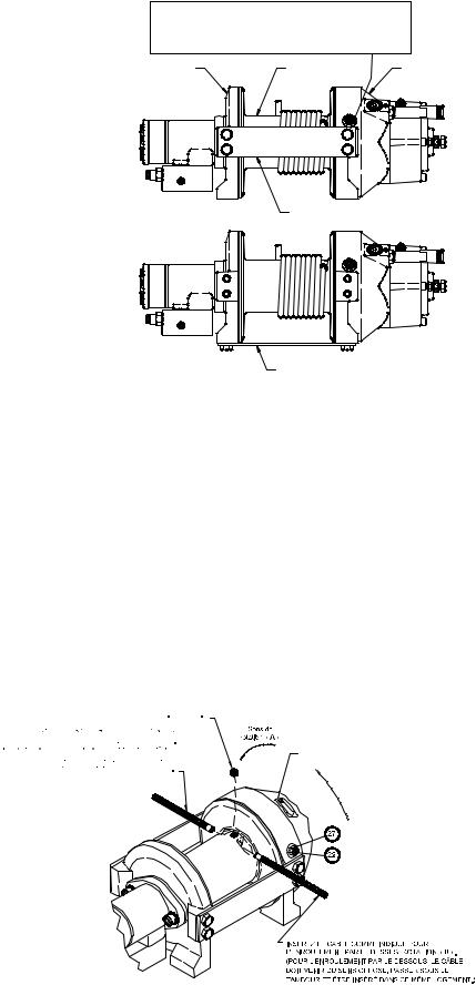
FIXATION DU TREUIL
INSTRUCTIONS DE MONTAGE IMPORTANTES POUR MAINTENIR L’ALIGNEMENT DES ÉLÉMENTS DU TREUIL À PLANÉTAIRE :
Ce treuil doit absolument être monté correctement afin que les trois principales parties soient alignées (l’extrémité du carter d’embrayage, le tambour du câble et l’extrémité de la boîte d'engrenages).
À des fins de conformité, s’il s’agit d’un montage de treuil intermédiaire, il convient de fixer au moins une plaque de serrage aux pieds de fixation au bas du treuil pour maintenir l’alignement. REMARQUE : si le treuil est installé sur pieds, au moins une plaque de serrage doit être placée au point intermédiaire pour maintenir l’alignement. Il est toujours souhaitable d’u- tiliser les deux plaques de serrage pour l’installation finale.
Il est conseillé d’utiliser le coffret de montage sur cornières, nº 251006 (pour tambour « Standard ») et nº 251007 (pour tambour « Y ») pour faciliter l’installation du treuil. Ce coffret permet de s’adapter aux installations verticales ou intermédiaires, et constitue une surface de montage droite et solide.
Si vous installez le treuil sans le coffret de cornières Ramsey recommandé, il convient alors d’utiliser les trous de fixation décrits en page 14. La surface de fixation doit être plane, à 0,38 mm près, et suffisamment rigide pour ne pas fléchir. Si une plaque d’acier est employée pour l’installation sur pied, elle doit mesurer 19 mm d’épaisseur. Pour ce type de montage, vous aurez besoin de huit vis d’assemblage 1/2-13 NC x 1,5 po de long, grade 5, avec leurs rondelles de sécurité. Ces vis devront être serrées à un couple de 115 Nm.
MISE EN GARDE : en cas d'utilisation de boulons plus longs (grade 5 minimum) pour la fixation du treuil ou d'un guide à galets au niveau des cales de fixation latérales, la longueur des boulons ne doit pas permettre un engagement des filets de moins de 12 mm dans les trous taraudés sur les côtés de chaque palier d'extrémité ( cf. page 15). Des boulons trop longs endommageraient le treuil et empêcheraient le tambour de tourner librement. Serrez les boulons à un couple de 75 Nm.
EXTRÉMITÉ MOTEUR |
TAMBOUR DU CÂBLE |
EXTRÉMITÉ BOÎTE |
|
D'ENGRENAGES |
|||
|
|
MONTAGE SUR PIED |
PLAQUE DE SERRAGE LATÉRALE |
|
PLAQUE DE SERRAGE AU PIED (BASE)
MONTAGE INTERMÉDIAIRE
REMARQUE : si des cornières ou une plaque d’acier sont utilisées pour
l’installation du treuil, les plaques de serrage fournies doivent être fixées aux cales de montage restantes, qu’elles soient latérales ou inférieures.
INSTALLATION DU CÂBLE
Un autocollant placé sur le dessus du palier d’extrémité indique le sens de l’enroulement du câble. Les lettres « A » ou « B » figurent aussi sur le palier d’extrémité, côté frein, pour indiquer le sens de rotation. Si cet autocollant est détérioré ou illisible, contactez le service clientèle pour savoir comment déterminer le sens de rotation correct.
1.Déroulez le câble sur le sol pour éviter qu'il ne se torde. Recouvrez bien l’extrémité du câble opposée au crochet d’un ruban adhésif plastique ou de type équivalent pour éviter qu’il ne s’effiloche.
2.Placez l’extrémité effilée du câble dans le trou du tambour, comme indiqué ci-dessous. Utilisez une vis de pression à tête creuse hexagonale 3/8-16 NC x ½ po de long (sur le tambour « Y » 234165 et sur le tambour « Standard » 234166) pour fixer le câble au tambour.
3.Faites tourner avec précaution le treuil dans le sens de l’enroulement. Conservez une tension sur l’extrémité du câble et enroulez tout le câble sur le tambour en veillant à former des couches régulières.
Une fois le câble installé, vérifiez que le tambour
tourne librement. Désenclenchez l’embrayage et tirez 


 sur le câble en marchant. Si le câble se détend et


 forme des boucles autour du tambour, desserrez le


 contre-écrou (pièce nº 27) et tournez la vis en Nylon


 (pièce nº 22) dans le sens des aiguilles d’une mon-
tre pour augmenter le frottement sur le tambour. Si le frottement est trop important, desserrez cette vis en
la tournant dans le sens inverse des aiguilles d’une montre. Serrez le contre-écrou une fois le réglage correct obtenu.
MISE EN GARDE : tout serrage excessif du contreécrou pourrait fausser le filet de la vis de pression en Nylon.
Sens de rotation « B »
25
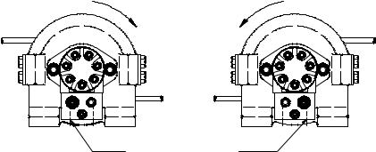
SENS DE ROTATION |
SENS DE ROTATION |
DU TAMBOUR |
DU TAMBOUR |
ENTRÉE
CORRESPONDANT À L'ENROULEMENT
SENS DE ROTATION « A » |
SENS DE ROTATION « B » |
ENTRETIEN
1.Examinez l’état du câble et lubrifiez-le fréquemment. Tout câble effiloché ou comportant des brins brisés doit être remplacé immédiatement. Il est possible de se procurer un ensemble câble-crochet (câble de 30 mètres) nº réf. 524118 (tambour « Y ») ou (câble de 45 mètres) nº réf. 524119 (tambour « Standard ») auprès d’un distributeur Ramsey.
2.Assurez-vous que l’embrayage est complètement enclenché. Reportez-vous aux instructions de la rubrique FONCTIONNEMENT, cidessus, selon le type d’embrayage. POUR LES EMBRAYAGES MANUELS UNIQUEMENT : tous les mois, désenclenchez l'embrayage, placez plusieurs gouttes d'huile sur l'arbre et manipulez plusieurs fois l'embrayage pour lubrifier l’intérieur du cylindre.
3.Vérifiez le frein afin de vous assurer de l’absence de glissement. Reportez-vous à la page 27.
4.Assurez-vous que le câble ne se détend pas pour former de larges boucles lors du déroulement libre. Reportez-vous à la page 25.
5.Remplacez les bagues du tambour ainsi que les joints lorsqu'ils commencent à perdre de la graisse. Reportez-vous aux INSTRUCTIONS DE RÉVISIONS en page 30-32. Le cas échéant, ajoutez du lubrifiant, Mobilith SHC 007, aux engrenages.
FONCTIONNEMENT
Pour vous familiariser avec votre treuil, il est vivement conseillé de l’essayer avant de vraiment l’utiliser. Préparez votre essai à l’avance. N’oubliez pas que vous entendez votre treuil autant que vous le voyez fonctionner. Apprenez à reconnaître le son d'une traction légère et régulière, celui d'une lourde charge ou encore celui provoqué par des à-coups ou une déviation de la charge. Évitez tous risques de glissements de la charge ou d’à-coups à son niveau, car ils pourraient représenter de dangereuses conditions.
L’embrayage du treuil permet un déroulement rapide du câble, à partir du tambour, afin de le fixer à une charge. L’embrayage est actionné au moyen de sa manette ou du cylindre pneumatique.
AVERTISSEMENT : NE RELÂCHEZ JAMAIS L’EMBRAYAGE EN PRÉSENCE D’UNE CHARGE!
EMBRAYEUR MANUEL (cf. page 33)
POUR DÉSENCLENCHER L’EMBRAYAGE – Faites fonctionner le treuil dans le sens de déroulement jusqu'à ce que le câble ne tracte plus la charge. Tirez sur la poignée et tournez-la de 90º. Avec la poignée en position « DÉSENCLENCHÉE », le tambour peut désormais tourner librement.
POUR ENCLENCHER L’EMBRAYAGE – Tirez sur la poignée, faites-la tourner de 90º, puis relâchez-la. Faites fonctionner le treuil dans le sens inverse jusqu’à ce que la poignée s’enclenche en position « ENCLENCHÉE ». N’essayez PAS de treuiller une charge si la poignée n'est pas complètement « ENCLENCHÉE ». Si le témoin lumineux d’embrayage manuel est présent, la lumière verte s’allume lorsque l’embrayage est « ENCLENCHÉ ». N’essayez PAS de treuiller une charge si le témoin vert n’est pas allumé. Pour brancher ce voyant sur le système électrique du véhicule, reportez-vous au schéma de câblage de la page 34.
EMBRAYEUR À CYLINDRE PNEUMATIQUE (cf. page 34)
POUR DÉSENCLENCHER L’EMBRAYAGE – Faites fonctionner le treuil dans le sens de déroulement jusqu'à ce que le câble ne tracte plus la charge. Appliquez une pression pneumatique à l’orifice de 0,125-27 NPT de 550 kPa (minimum) à 1 030 kPa (maximum). MISE EN GARDE : la pression ne doit pas dépasser 1 030 kPa.
POUR ENCLENCHER L’EMBRAYAGE – Retirez la pression pneumatique du cylindre (un ressort de rappel enclenche le piston plongeur). Faites fonctionner le treuil dans le sens inverse jusqu'à ce que le témoin lumineux d'enclenchement de l'embrayage (voyant vert) s’allume. N’essayez PAS de treuiller une charge si le témoin vert n’est pas allumé. Pour brancher ce voyant sur le système électrique du véhicule, reportez-vous au schéma de câblage en page 34.
26
 Loading...