


OPERATING, SERVICE AND
MAINTENANCE MANUAL
English (Original Instructions) . . . . . . . . . . . . . . . 1
Français (Traduction des instructions originales) . . 19
Deutsch (Übersetzung der Originalanleitung) . . . . . 37
Español(Traducción de las instrucciones originales).55
MODEL DC 34,9
RAM-LOK® EQUIPPED
INDUSTRIAL LOW-MOUNT WINCHES
CAUTION: READ AND UNDERSTAND THIS MANUAL BEFORE INSTALLATION AND OPERATION OF WINCH. SEE WARNINGS!
INTENDED USE: VEHICLE RECOVERY AND PULLING OF LOADS
Ramsey Winch Company
P.O. Box 581510 - Tulsa, OK 74158-1510 USA
Phone: (918) 438-2760 - Fax (918) 438-6688
Visit us at http://www.ramsey.com
Ramsey Authorized Representative in the Community:
(Please contact for regultory inquiries only.)
Alura Group BV
P.O. Box 18626
2502 EP The Hague
The Netherlands
Tel: (31) (0) 70 362-4896
Fax: (31) (0) 70 346-7299
OM-914219-1012-C

|
4707 N. Mingo |
Tulsa, Oklahoma 74117 |
(918) 438-2760 |
|
||
|
|
|
|
|
|
|
|
|
|
|
|
|
|
EC DECLARATION OF CONFORMITY |
|
DÉCLARATION DE CONFORMITÉ EC |
||||
as defined by Machinery Directive 2006/42/EC |
|
aux termes de la directive Machines 2006/42/EC |
||||
Here with we declare that winch model DC34, 9 com- |
|
Nous déclarons par la présente que le modèle de treuil DC34, |
||||
plies with the following directive provided that the USER |
9 est conforme à la directive suivante, sous réserve que |
|||||
complies with all responsibilities described in the Owner’s |
l’UTILISATEUR ait assumé toutes les responsabilités figurant |
|||||
Manual: |
|
dans le manuel de l’utilisateur |
: |
|
||
2006/42/EC |
|
2006/42/EC |
|
|
||
Applied harmonized standards: |
|
Normes harmonisées appliquées : |
||||
EN 14492-1:2006 |
|
EN 14492-1:2006 |
|
|
||
Power-Driven Winches |
|
|
|
|||
|
Treuils motorisés |
|
|
|||
ISO 9001:2000 |
|
|
|
|||
|
ISO 9001:2000 |
|
|
|||
Quality Management Systems |
|
|
|
|||
|
Systèmes de gestion de la qualité - Exigences |
|||||
Requirements |
|
|||||
|
|
|
|
|||
|
|
|
|
|
|
|
EC-KONFORMITÄTSERKLÄRUNG |
|
DECLARACIÓN EC DE CONFORMIDAD |
||||
gemäß Maschinenrichtlinie 2006/42/EC |
|
según se define en la directiva de máquinas 2006/42/EC |
||||
|
|
|
|
Con la presente declaramos que el modelo de cabestrante |
||
Hiermit erklären wir, dass das Windenmodell DC34, 9 der |
DC34, 9 se halla en conformidad con la siguiente directiva |
|||||
folgenden Richtlinie entspricht, sofern der BENUTZER |
|
siempre que el USUARIO cumpla todas las responsabi- |
||||
alle Anweisungen im Benutzerhandbuch befolgt: |
|
lidades descritas en el Manual del propietario: |
||||
2006/42/EC |
|
2006/42/EC |
|
|
||
Angewandte harmonisierte Normen: |
|
Normas armonizadas aplicadas: |
||||
EN 14492-1:2006 |
|
EN 14492-1:2006 |
|
|
||
Kraftgetriebene Winden |
|
Cabestrantes accionados mecánicamente |
||||
ISO 9001:2000 Qualitätsmanagementsysteme - |
|
ISO 9001:2000 |
|
|
||
Anforderungen |
|
Requisitos de los Sistema de gestión de la calidad |
||||
|
|
|
|
|
|
|
Ramsey Authorized Representative in the Community / Ramsey Représentant autorisé dans la comuauté / Ramsey Bevollmächtigter in der Europäischen Union / Ramsey Representante autorizado en la comunidad.
(Please contact for regulatory inquiries only. / Veuillez prendre contact uniquement pour des questions réglementaires.) (Bitte nur bei Regulierungsfragen kontaktieren. / Póngase en contacto sólo por cuestiones de reglamentación.)
Alura Group BV
P.O. Box 18626
2502 EP The Hague
The Netherlands
Tel: (31) (0) 70 362-4896
Fax: (31) (0) 70 346-7299
Serial Number / Numéro de série/ Seriennummer/ Número de Serie:_____________________
Signature / Signature / Unterschrift / Firma: |
Date / Date / Datum / Fecha: |
||||
|
|
Todd Brady |
05/03/11 |
|
|
|
|
||||
Engineering Manager / Directeur technique/ Technischer Leiter/ Director de ingeniería |
|
|
|
||
|
|
|
|
|
|
2
TABLE OF CONTENTS
USER’S RESPONSIBILITY FOR CE COMPLIANCE . .. . . . . . . . . . . . . . . . . . . . . . . . . . . . . . . . . 4 SPECIFICATIONS . . . . . . . . . . . . . . . . . . . . . . . . . . . . . . . . . . . . . . . . . . . . . . . . . . . . . . . . . . . . .4 WARNINGS . . . . . . . . . . . . . . . . . . . . . . . . . . . . . . . . . . . . . . . . . . . . . . . . . . . . . . . . . . . . . . . . . . 4 WINCH MOUNTING . . . . . . . . . . . . . . . . . . . . . . . . . . . . . . . . . . . . . . . . . . . . . . . . . . . . . . . . . . . 5 ROPE INSTALLATION . . . . . . . . . . . . . . . . . . . . . . . . . . . . . . . . . . . . . . . . . . . . . . . . . . . . . . . . . 5 TECHNIQUES OF OPERATION . . . . . . . . . . . . . . . . . . . . . . . . . . . . . . . . . . . . . . . . . . . . . . . . . . 5 WINCH MAINTENANCE . . . . . . . . . . . . . . . . . . . . . . . . . . . . . . . . . . . . . . . . . . . . . . . . . . . . . . . 6 ELECTRICAL CONNECTIONS . . . . . . . . . . . . . . . . . . . . . . . . . . . . . . . . . . . . . . . . . . . . . . . . . . 6 RATED LOAD LIMITER ADJUSTMENT . . . . . . . . . . . . . . . . . . . . . . . . . . . . . . . . . . . . . . . . . . . . 6 END OF SERVICE MEASURES . . . . . . . . . . . . . . . . . . . . . . . . . . . . . . . . . . . . . . . . . . . . . . . . . 5 TROUBLE SHOOTING GUIDE . . . . . . . . . . . . . . . . . . . . . . . . . . . . . . . . . . . . . . . . . . . . . . . . . . . 7 INSTRUCTIONS FOR OVERHAUL DISASSEMBLY . . . . . . . . . . . . . . . . . . . . . . . . . . . . . . .8-11 REASSEMBLY . . . . . . . . . . . . . . . . . . . . . . . . . . . . . . . . . . . . . . . . . . . . . . . . . . . . . . . . . . . . 11-12 DIMENSIONAL DRAWING . . . . . . . . . . . . . . . . . . . . . . . . . . . . . . . . . . . . . . . . . . . . . . . . . . . . . 13 PARTS LIST AND PARTS DRAWING . . . . . . . . . . . . . . . . . . . . . . . . . . . . . . . . . . . . . . . . . . 14-15 SOLENOID ASSEMBLY PARTS LIST . . . . . . . . . . . . . . . . . . . . . . . . . . . . . . . . . . . . . . . . . . . . 16 TEST PROCEDURE FOR SOLENOID . . . . . . . . . . . . . . . . . . . . . . . . . . . . . . . . . . . . . . . . . . . . 17 TEST PROCEDURE FOR MOTOR . . .. . . . . . . . . . . . . . . . . . . . . . . . . . . . . . . . . . . . . . . . . . .18
3
* SPECIFICATIONS:
Ambient Temp Range |
|
|
|
|
|
|
-28C to 60C (-20F to 140F) |
|||||
Noise Level |
|
|
|
|
|
|
|
|
|
|
80db |
|
|
|
|
|
|
|
|
|
|
|
|
||
LAYER OF ROPE |
|
|
|
|
|
1 |
|
|
2 |
|
3 |
|
Rated Line Pull Per Layer |
|
|
|
kN |
34,9 |
|
|
28,9 |
|
24,9 |
|
|
|
|
|
lb |
7,840 |
|
|
6,500 |
|
5,600 |
|
||
|
|
|
|
|
|
|
|
|||||
Cummulative Rope Capacity Per Layer (Long |
|
m |
7 |
|
|
16 |
|
28 |
|
|||
Drum) |
|
|
|
ft |
25 |
|
|
55 |
|
95 |
|
|
Cummulative Rope Capacity Per Layer (Short |
|
m |
3 |
|
|
9 |
|
15 |
|
|||
Drum) |
|
|
|
ft |
10 |
|
|
30 |
|
50 |
|
|
|
|
|
|
|
|
|
|
|
|
|
|
|
Line Pull First Layer |
kN |
No |
Load |
|
8,8 |
|
17,7 |
|
34,9 |
|
||
|
|
|
|
|
|
|
|
|
||||
lb |
|
2,000 |
|
4,000 |
|
7,840 |
|
|||||
|
|
|
|
|
|
|
|
|||||
|
|
|
|
|
|
|
|
|
|
|
|
|
* DC 34,9 & DCY 34,9 Line |
MPM |
|
4,3 |
|
|
2,1 |
|
1,5 |
|
1,7 |
|
|
Speed First Layer 12 V & |
|
|
|
|
|
|
|
|
|
|
|
|
FPM |
|
14 |
|
|
7 |
|
5 |
|
3.5 |
|
||
24V |
|
|
|
|
|
|
||||||
*DC 34,9 & DCY 34,9 Amp |
12V |
|
65 |
|
|
110 |
|
180 |
|
370 |
|
|
Draw |
24V |
|
30 |
|
|
50 |
|
90 |
|
140 |
|
|
|
|
|
|
|
|
|
||||||
|
|
|
|
|
|
|
|
|||||
* These specifications are based on recommended 10 mm (.393”) 1960 grade wire rope. |
|
|
||||||||||
|
|
|
|
|
|
|
|
|
|
|
|
|
WARNINGS:
THE USER SHALL ENSURE THAT THE OPERATING PERSONNEL ARE GIVEN THE NECESSARY TRAINING. THE OPERATOR SHALL ALWAYS WORK IN COMPLIANCE WITH THE OPERATING INSTRUCTIONS. CLUTCH MUST BE FULLY ENGAGED BEFORE STARTING THE WINCH.
DO NOT DISENGAGE CLUTCH UNDER LOAD.
STAY OUT FROM UNDER AND AWAY FROM RAISED LOADS.
STAND CLEAR OF ROPE WHILE PULLING. DO NOT TRY TO GUIDE ROPE.
DO NOT USE WINCH TO LIFT, SUPPORT, OR OTHERWISE TRANSPORT PERSONNEL.
A MINIMUM OF 2 WRAPS OF ROPE AROUND THE DRUM BARREL IS NECESSARY TO HOLD THE LOAD. AVOID CONDITIONS WHERE LOAD SHIFTS OR JERKS OCCUR. EXCESSIVE “INCHING” SHALL BE AVOIDED.
User’s Responsibility for CE Compliance
1.Mount winch per Installation Instructions.
2.Install the emergency stop switch per Installation Instructions included with the Emergency Stop Switch Kit.
3.Install 10 mm (.393 in) grade 1960 wire rope. Maximum Rope length of 28 M (95 ft) for three layers maximum.
4.Attach rope to the drum per Rope Installation Instructions.
5.Use a hook which includes a safety latch and has a minimum breaking strength of 87 kN.
4
WINCH MOUNTING
It is most important that this winch be mounted securely so that the three major sections (the clutch housing end, the rope drum and the gear housing end) are properly aligned.
All standard model DC 34,9 winches are furnished with recommended mounting angles. Angle size is 9 x 63 x 63 x 914 mm (3/8 x 2-1/2 x 2-1/2 x 36”) Lg. high strength 344,500 KPa (50,000 PSI) yield steel angle.
ROPE INSTALLATION
1. Unwind rope by rolling it out along the ground to prevent kinking. Securely wrap end of rope, opposite hook, with plastic o r similar tape to pre vent fraying.
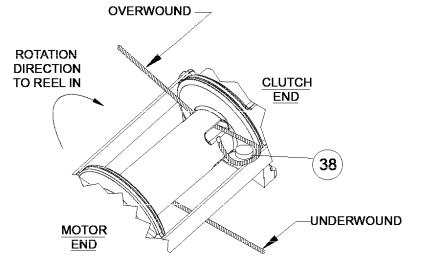
2.Slide the wire rope through narrow end of the pocket against the drum flange. Wrap the wire rope around on the anchor “puck” (item #38) and pull the wire rope and anchor back into the wide end of the pocket. Use a soft hammer to drive the back side of the wire rope, firmly seating the wire rope and anchor into the pocket.
3.Carefully run winch in the “reel-in” direction. Keeping tension on end of rope, spool all the rope onto the rope drum, taking care to form neatly wrapped layers.
TECHNIQUES OF OPERATION
The uneven spooling of rope, while pulling a load, is not a problem, unless there is a rope pileup on one end of drum. If this happens, reverse the winch to relieve the load and move your anchor point further to the center of the vehicle. After the job is done you can unspool and rewind for a neat lay of the rope
When pulling a load where there is even a remote chance of rope failure, place a blanket, jacket or tarpaulin over the rope about six feet behind the hook. This will slow the snap back of a broken rope and could prevent serious injury.
Check oil level of winch every six months. Replace oil annually or more often if winch is used frequently. Use 0.35 L (0.75 pint) of all purpose E.P. 140 oil in the worm gear housing and 0.23 L (0.5 pint ) SAE 20 for spur gear box. If the oil is contaminated with metallic particles, inspect winch for cause of abnormal wear.
Periodically check all electrical connections and mounting bolts. Tighten hardware if necessary.
The minimum ampere-hour rating of vehicle battery should be 70, and used with at least a 40 ampere alternator. An auxiliary battery is recommended to supply additional battery power.
Inspect the rope frequently. If the rope becomes frayed with broken strands, replace immediately. The RAM-LOK® semi-automatic clutch allows rapid unspooling of the rope, from rope drum, for hooking onto a load. The clutch is operated by the “T-handle”, located on the end of the winch, as follows:
1.TO DISENGAGE CLUTCH, run the winch in the reverse (reel out) direction until the load is off the rope. Pull outward on the clutch handle, rotate it counter-clockwise 90º and release. The clutch is now locked out and the rope may be pulled off by hand.
2.TO ENGAGE CLUTCH, pull outward on the handle, rotate it clockwise 90º and release. Run the winch in reverse until the clutch handle snaps fully in or until the rope drum starts turning. At this point make sure the clutch handle is all the way in. The plastic plug in top of clutch housing may be removed, for inspection of clutch to assure total engagement. After the clutch is fully engaged, the winch is ready for winching in the rope.
5
WINCH MAINTENANCE
Adhering to the following maintenance schedule will keep your winch in top condition and performing as it should with a minimum of repair.
A. |
WEEKLY |
1. |
Check the oil level and maintain it to the oil level plug. If oil is leaking out, determine location and repair. |
2. |
Check the pressure relief plug in top of the gear housing. Be sure that it is in good operating condition so that hot oil gasses |
|
may escape. |
3. |
Lubricate rope with light oil. |
B. |
MONTHLY |
1.Lubricate the various grease fittings located in the rope drum, end bearing, clutch housing or clutch operating linkage. Any good grade of moly-disulfide containing grease is acceptable.
2.Check the action of the sliding clutch, making sure it is fully engaging and disengaging with the rope drum. Remove the plastic plug in top of the housing and observe if the clutch is fully engaging. If clutch is not fully engaging, inspect clutch shifter assembly parts, check for damage or excessive wear and replace as necessary. Observe the jaws on both the clutch and rope drum, checking for rounding of the driving faces. If rounding has occurred they should be replaced immediately.
3.Check the winch mounting bolts. If any are missing, replace them and securely tighten any that are loose. Make sure to use only grade 5 bolts or better.
4.Inspect the rope. If the rope has become frayed with broken strands, replace immediately.
C.ANNUALLY
1.Drain the oil from the winch annually or more often if winch is used frequently.
2.Fill the winch to the oil level plug with clean kerosene. Run the winch a few minutes with no load in the reel in direction. Drain the kerosene from the winch.
3.Refill the winch to the oil level plug with all purpose E.P. 140 gear oil.
4.Inspect frame and surrounding structure for cracks or deformation.
5.Gear wear can be estimated by rocking the drum back and forth and if necessary drain oil and remove cover for closer inspection.
ELECTRICAL CONNECTIONS
For normal self-recovery work, your existing electrical system is adequate. Your battery must be kept in good condition. A fully charged battery and proper connections are essential. Run the vehicle engine during winching operation to keep battery charged. Connect red cable from stud on plastic solenoid cover on winch to emergency stop solenoid. Important:
Hold inner nut with end wrench while tightening outer nut. Install emergency stop switch and solenoid per kit # 282067 (12V) or 282068 (24V) as applicable.
Connect black cable from motor ground stud to negative battery termi nal. A good electrical ground is required for proper performance. The remote control switch is waterproof and has push button stations on either side. It is designed this way to prevent quick winch reversals, which lead to solenoid failure. Make sure the winch motor has stopped fully before reversing. When first setting up your winch, follow the directions for inserting the proper “IN” or “OUT” label in the thumb button. The switch is also color coded to aid you in determining the direction your winch will run.
ADJUSTMENT OF RATED LOAD LIMITER
1.Make some test pulls with winch (using a load cell or spring scale) to determine if switch is at desired rated load set ting.
Applicable setting is 100% to 125% of rated load.
2.If load is not within above range, remove tamper-proof compound in threaded hole (on top of set screws #4). Remove top set screw.
3.Loosen bottom set screw approximately 2 turns counter clockwise.
4.To reduce line pull, thread switch #1 “IN” by turning clockwise. To increase line pull, the switch “OUT”.
5.After desired setting is reached, tighten bottom set screw securely.
6.Re-install top set screw and tighten securely. Fill threaded hole with a potting-type compound which must be removed before any future adjustment is made.
When winch reaches the end of its serviceable life, dispose of per local environmental regulations.
6
TROUBLESHOOTING GUIDE
CONDITION |
|
POSSIBLE CAUSE |
|
CORRECTION |
CLUTCH INOPERATIVE OR |
1. Dry or rusted shaft. |
1. |
Clean and lubricate. |
|
BINDS UP. |
2. |
Bent yoke or linkage. |
2. |
Replace yoke or shaft assembly. |
|
||||
|
3. |
Clutch jaws are in contact. |
3. |
See TECHNIQUES OF OPERATION. |
|
|
|
|
|
OIL LEAKS FROM HOUSING. |
1. Seal damaged or worn. |
1. |
Replace seal. |
|
|
2. |
Too much oil. |
2. |
Drain excess oil. Refer to TECHNIQUES OF OPERATION. |
|
3. |
Damaged gasket. |
3. |
Replace gasket. |
|
|
|
|
|
WINCH WILL NOT PULL RATED |
1. |
Rated load limiter mis-adjusted. |
1. |
Adjust rated load limiter per instructions on page 5. |
LOAD |
|
|
|
|
|
|
|
|
|
CABLE DRUM WILL NOT |
1. Winch not mounted squarely, caus- |
1. |
Check mounting. Refer to WINCH MOUNTING Page 5. |
|
FREE SPOOL. |
|
ing end bearings to bind drum. |
|
|
|
|
|
|
|
CABLE BIRDNESTS WHEN |
1. Drag brake disc worn. |
1. |
Replace discs. |
|
CLUTCH IS DISENGAGED. |
|
|
|
|
|
|
|
|
|
MOTOR RUNS IN ONE |
1. Inoperative solenoid or stuck sole- |
1. |
Jar solenoid to free contacts. Check by applying 12 volts to coil |
|
DIRECTION ONLY. |
|
noid. |
|
terminal (it should make an audible click when energized). |
|
2. |
Inoperative switch. |
2. |
Disengage winch clutch or remove armature lead. Remove switch |
|
|
|
|
plug from hood. Raise connector cover on hood and with a |
|
|
|
|
screwdriver, short the bottom two pins. Solenoid should click. |
|
|
|
|
Short the two left hand pins. The other solenoid should operate. If |
|
|
|
|
both solenoids operate, check for a broken wire in switch cable. |
|
3. |
Broken wire or bad connection. |
3. |
Check for loose connection on switch and switch connector. |
|
|
|
||
MOTOR RUNS, BUT DRUM |
1. Clutch not engaged. |
1-4. If clutch engaged but symptom still exists, it will be necessary |
||
DOES NOT TURN. |
2. Sheared drum shaft key. |
|
to disassemble winch to determine cause and repair. |
|
|
3. Stripped bronze gear. |
|
|
|
|
4. |
Parted shaft. |
|
|
|
|
|
|
|
MOTOR RUNS EXTREMELY |
1. Long period of operation. |
1. |
Cooling-off periods are essential to prevent over-heating. |
|
HOT. |
|
|
|
|
|
|
|
|
|
MOTOR RUNS, BUT WITH |
1. Insufficient battery. |
1. |
Check battery terminal voltage under load. If 10 volts or less, |
|
INSUFFICIENT POWER, OR |
|
|
|
replace or parallel another battery to it at motor terminal. |
WITH LOW LINE SPEED. |
2. |
Electrical cables from battery to |
2. |
Must be #2 gauge wire for distances up to 4,5 m (15 ft) from |
|
||||
|
|
winch too small. |
|
battery to winch. Use larger than #2 gauge for distances greater |
|
|
|
|
than 4,5 m (15 ft). |
|
3. |
Bad electrical connections. |
3. |
Check all connections for looseness or corrosion. Tighten, clean |
|
|
|
|
and grease. |
|
4. |
Insufficient charging system. |
4. |
Replace with larger capacity charging system. |
|
|
|
|
|
MOTOR WILL NOT |
1. Inoperative solenoid or stuck sole- |
1. |
Jar solenoid to free contacts. Check by applying 12 volts to coil |
|
OPERATE. |
|
noid. |
|
terminal (it should make an audible click when energized). |
|
2. |
Inoperative switch. |
2. |
Disengage winch clutch or remove armature lead. Remove switch |
|
|
|
|
plug from hood. Raise connector cover on hood and with a |
|
|
|
|
screwdriver, short the bottom two pins. Solenoid should click. |
|
|
|
|
Short the two left pins. The other solenoid should operate. If both |
|
|
|
|
solenoids operate, check for a broken wire in switch cable. |
|
3. |
Inoperative motor. |
3. |
If solenoids operate, check for voltage at armature post, replace |
|
|
|
|
motor. |
|
4. |
Loose connections. |
4. |
Tighten connections on bottom side of hood and on motor. |
|
|
|
|
|
7
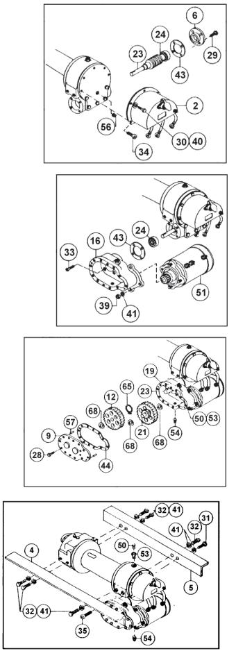
INSTRUCTIONS FOR OVERHAUL OF RAMSEY MODEL DC 34,9 SERIES RAM-LOK®
DIS-ASSEMBLY
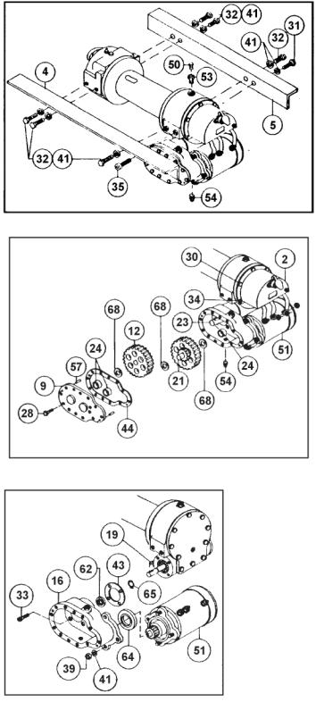
1.Drain oil from worm gear housing by removing (item #54) plug from bottom of gear housing. Remove relief fitting and reducer (items #50 & #53) from top of gear housing. Remove mounting angles (items #4 & #5) from winch by removing hardware shown.
2.Drain oil from spur gear housing by removing (item #54) plug. Remove cover and gasket (items #9 & #44) from spur gear housing by unscrewing twelve capscrews (item #28). Slide gear (item #12) from end of worm shaft (item #23). Remove spur gear shaft (item #21), with gears attached. Check bearings (item #24) and thrust washers (item #68) for signs of wear, replace if necessary. Remove old bearings and press new bearings into place. Remove solenoid assembly (item #2) by unscrewing capscrews (items #30 & #34). Disconnect solenoid cables from motor (item #51). Make note of which terminals cables are attached to.
3.Remove key (item #19) and snap ring (item #65) from worm shaft. Remove motor (item #51) from spur gear housing (item #16) by removing (3) nuts and lock washers (items #39 & #41). Unscrew (4) capscrews (item #34) to remove spur gear box (item #16) and gasket (item #43) from gear housing. Replace lip seals (items #62 & #64) by pressing old seals from spur gear housing and pressing new seals into place.
8
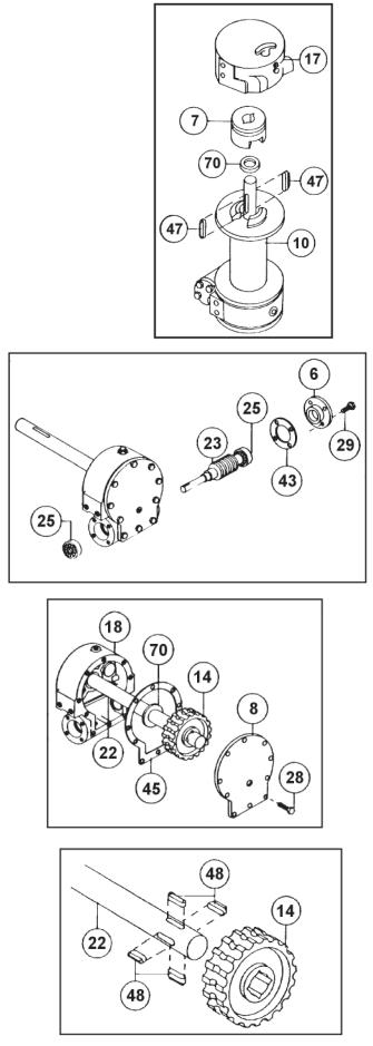
4.Slide clutch housing (item #17) from end of drum shaft. Slide jaw clutch (item #7) from end of drum shaft.
Remove (2) keys (item #47) from keyways. A screwdriver can be used, at notch, to aid in removal of keys. Once keys have been removed, drum (item #10) and thrust washer (item #70) can be removed from drum shaft. Parts under drum, thrust washer (item #69), spring and disc (item #66 & #42) should also be removed.
5.Remove bearing cap (item #6) from gear housing by unscrewing four capscrews (item #29). Remove worm (item #23) and bearing (item #25) from gear housing. Use a soft hammer to gently tap input end of worm and drive worm and bearing from gear housing. Once worm has been removed from housing, bearing can be pressed from end of worm.
Check for signs of wear to worm (item #23) and bearings (item #25). Replace if necessary.
For models with optional worm brake refer to page 6, SERVICING OF THE OIL COOLED SAFETY BRAKE, for disassembly and Page 7, for re-assembly instructions.
6.Remove gear housing cover (item #8) from gear housing (item #18) by unscrewing five remaining capscrews (item #28). Place capscrew into two tapped holes of cover and tighten. This will pull the cover loose from gear housing.
Remove cover gasket (item #45) and pull shaft (item #22), with gear attached, and thrust washer (item #70) from gear housing.
7.Check for signs of wear on gear teeth. If replacement of gear is necessary, gear must be replaced as follows:
a.Press gear (item #14) from shaft (item #22).
b.Examine shaft keys and keyways. If distortion of keys and/or keyways is evident, shaft and keys should be replaced.
c.Use a soft hammer to gently tap keys (item #48) into keyways. Press gear (item #14) over shaft and keys. Gear must be centered over keys.
9
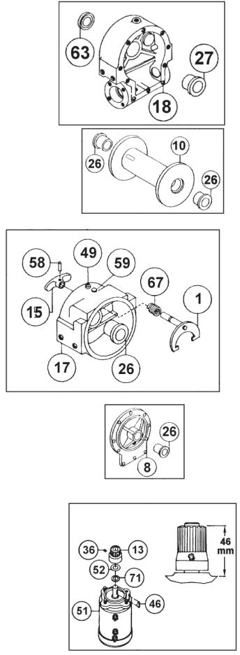
8.Remove seal (item #63) from back of gear housing (item #18). Check bushing (item #27) for signs of wear. Press bushing (item #27) from gear housing and replace if necessary. Press new bushing and seal back into place.
9.Check drum bushings (item #26) for signs of wear. Replace if necessary by pressing old bushings from drum (item #10) and pressing new ones into place.
10.Examine shifter assembly (item #1) for damage to yoke. Yoke should be firmly attached to shaft, yet, able to swivel freely around shaft. Replace if necessary by removing pin (item #58) from handle (item #15). Remove rubber plug (item #59) from housing. Unscrew setscrew enough to allow shifter assembly to be removed from housing.
Check clutch housing bushing (item #26) fro signs of wear. Remove if necessary by pressing old bushing from housing (item #17) and pressing new one into place.
Install new shifter assembly (item #1) by placing end of shaft, opposite yoke, through spring (item #67) and into housing (item #17). Attach handle (item #15) to shaft using roll pin (item #58). Tighten setscrew, in housing, enough to allow shifter assembly to operate properly. Replace rubber plug.
11.Check cover bushing (item #8) for signs of wear. Replace if necessary by removing old bushing and pressing new bushing into place.
12.Check pinion gear on motor for signs of wear. If necessary replace gear (item #13), o-ring (item #52) and fiber washer (item #71) as follows:
a.Place fiber washer (item #71) and well oiled o-ring (item #52) over end of motor shaft and down to bottom of shaft.
b.Insert key (item #46) into motor shaft keyway. Slide pinion gear over shaft and key. Use a hammer and 7/8” (22 mm) I.D. (internal diameter) tube to drive pinion down hard enough to seat o-ring (item #52) into groove in bottom of pinion gear.
c.Slide pinion gear up toward end of shaft so that there is a 1-13/16” (46 mm) distance from top of gear to cast surface below gear. Tighten setscrew (item #36) securely enough to prevent pinion gear from moving on motor shaft.
10
13.Check gears of spur gear shaft assembly for signs of wear, replace if necessary. Press old gears from shaft (item #21). Tap key (item #20) into keyway of shaft (item #21). Press shaft through gears so that gears are centered on shaft and key.
RE-ASSEMBLY
14.Apply grease to end of shaft, opposite gear. Apply grease to bushing in gear housing (item #18). Place greased end of shaft through thrust washer (item #70) and bushing in gear housing (item #18). Place gasket (item #45) onto gear housing cover (item #8). Apply grease to gear end of shaft and bushing in cover. Place cover onto shaft and secure to housing with five capscrews (item #28) at the five lower most holes.
15.Place winch, with gear housing cover down, on work bench. Drum shaft should be in vertical position. Slide thrust washer (item #69) over drum shaft and slide downwards until washer rests on gear housing. Set springs (item #66) and drag brake disc (item #42) into pockets of gear housing. Grease bushings in drum (item #10). Slide drum assembly onto drum shaft with drum jaws upward.
16.Place thrust washer (item #70) over end of drum shaft and slide downward until spacer rests on drum. Press drum (item #10) downward to compress springs in gear housing.
Insert keys (item #47) into keyways with sharp edge of keys pointing outward and notched end of keys upward. A rubber or brass mallet will be needed to gently tap keys into position.
Apply grease to keys and end of shaft. Place jaw clutch (item #7) over end of shaft and slide jaw clutch over keys.
Set clutch housing (item #17) over end of drum shaft. Pull jaw clutch (item #7) upward, toward clutch housing, enough to allow yoke, in clutch housing, to fit properly in groove around jaw clutch.
11
17.Press bearing (item #24) onto worm (item #23). NOTE: Be sure thick shoulder of bearings outer race (side with manufacturer’s name and part number) is out, away from worm threads. Press bearing and worm into gear housing. Slip gasket (item #43) onto bearing cap (item #6). Use four capscrews (item #29) to secure cap to gear housing. Torque capscrews to 7 ft-lbs. (9.4 Nm) each.
Attach solenoid assembly (item #2) to gear housing. Use two (item #34) capscrews and three (item #30) capscrews with three flatwashers (item #40). Tighten capscrews to 7 ft-lbs. (9.4Nm) each. Insert plug (item #56) into tapped hole of cover. Permatex may be applied to threads to help prevent oil leakage. TIGHTEN plug securely.
18.Press bearing (item #24) onto worm and into worm gear housing. NOTE: Be sure thick shoulder of bearings outer race (side with manufacturer’s name and number) is out, away from worm threads. Place gasket (item #43) onto spur gear housing (item #16). Secure spur gear housing to worm gear housing using four capscrews (item #33). Torque capscrews to 7 ft-lbs. (9.4 Nm) each.
Mount motor (item #51) to spur gear housing (item #16) using three lockwashers and nuts (items #39 & #41). Attach solenoid cables to motor terminals. Tighten all nuts securely.
19.Place snap ring (item #65) over end of worm shaft (item #23) and set into snap ring groove. Insert key (item #19) into keyway of worm shaft. Place thrust washer (item #68) over each end of spur gear shaft (item #21). Set spur gear shaft assembly into bearing of spur gear housing. Slide gear (item #12) and (item #68) thrust washer over end of worm shaft (item #23).
Insert pins (item #57) into cover (item #9). Place gasket (item #44) onto cover. Attach cover and gasket to spur gear housing using twelve capscrews (item #28). Torque capscrews to 8 ft-lbs. (10.8 Nm.) each.
Insert plug (item #54) into bottom of spur gear housing. Permatex may be applied to threads to help prevent oil leakage.
Remove reducer and fitting (items #50 & #53) from top of spur gear housing. Pour .24 liters (1/2 pt) of SAE 20 weight motor oil into spur gear box. Replace reducer and fitting into top of spur gear housing. Tighten reducer and fitting securely.
20.Attach mounting angles (items #4 & #5) using six capscrews (items #32) with lockwashers and capscrews (items #35 & #31). Torque capscrews to 34 ft-lbs. (46 Nm.) each. Insert plug (item #54) into bottom of gear housing. Permatex may be applied to threads to help prevent leakage.
Pour .35 liters (3/4 pt) of E.P. 140 gear oil into housing thru hole in top of housing. Insert relief fitting (item #50) into reducer (item #53). Reducer should then be placed into hole on top of gear housing. Tighten fitting and reducer securely.
12
WINCH |
A |
B |
C |
D |
INCHES |
INCHES |
INCHES |
INCHES |
|
MODEL |
MM |
MM |
MM |
MM |
|
|
|
|
|
|
|
|
|
|
DC 34,9 |
7.78 |
11.31 |
8.94 |
13.12 |
|
197,6 |
287,3 |
227,0 |
333,3 |
DCY 34,9 |
5.28 |
6.31 |
11.44 |
8.12 |
134,1 |
160,3 |
290,5 |
206,3 |
|
|
|
|
|
|
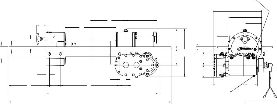
CONNECT POWER CABLE FROM
EMERGENCY STOP SOLENOID HERE
SEE 282067 (12V) OR 282068 (24V)
|
|
|
|
|
|
|
|
|
|
|
10.77 |
|
|
|
|
|
|
|
|
|
|
|
273,6 |
|
|
|
|
|
A |
|
|
|
|
|
7.44 |
|
|
|
|
|
6.75 |
|
|
|
|
188,9 |
|
CLUTCH AT |
|
2.12 |
|
B |
|
171,4 |
|
|
|
|
3.72 |
DIS-ENGAGED |
|
|
|
|
|
|
|
94,5 |
|||
53,9 |
|
|
|
|
|
|
|
|
|||
POSITION |
|
|
|
|
|
|
|
|
|
||
|
|
|
|
|
|
|
|
|
|
|
|
|
|
|
|
|
|
|
4.56 |
|
|
2.50 |
|
.49 |
|
|
|
|
|
|
|
|
63,5 |
|
|
|
|
|
|
|
|
115,8 |
|
|
|
||
12,6 |
|
2.19 |
|
|
|
|
.25 |
(TYP) |
(TYP) |
|
|
(TYP) |
|
55,6 |
|
|
|
|
|
6,4 |
|
|
|
|
|
|
|
|
|
|
|
|
|
|
|
2.50 |
|
|
|
|
|
|
|
10.25 |
|
|
|
63,5 |
|
|
|
|
|
|
|
|
|
|
|
|
|
|
|
|
|
|
260,3 |
|
|
|
|
(TYP) |
|
|
|
|
|
|
3.62 |
|
|
|
|
|
|
|
|
|
|
|
92,0 |
2.89 |
|
|
|
|
|
|
|
|
|
|
73,5 |
|
|
||
|
|
|
|
|
Ø3.59 |
|
|
|
|
||
|
|
|
|
DRUM |
|
|
|
|
|
|
|
13 |
|
|
|
|
89,9 |
|
|
|
|
|
|
|
|
.69 |
|
|
|
|
2.78 |
|
|
||
|
|
|
|
|
|
|
70,7 |
|
|
||
|
|
|
17,5 |
|
|
1.37 |
|
|
|
|
|
|
|
|
|
|
|
|
|
|
|
|
|
|
C |
2.50 |
D |
|
34,9 |
|
|
|
7.05 |
2.74 |
|
|
|
2.50 |
|
|
|
||||||
|
63,5 |
|
63,5 |
|
|
|
179,1 |
69,6 |
|||
|
|
|
|
25.03 |
|
|
CONNECT GROUND CABLE FROM |
|
|||
|
|
|
|
|
|
NEGATIVE (-) BATTERY TERMINAL TO |
|
||||
|
|
|
|
635,6 |
|
|
|
||||
|
|
|
|
|
|
MOTOR GROUND STUD |
|
||||
|
|
|
|
|
|
|
|
6.22 |
|||
|
|
|
|
36.00 |
|
|
|
|
|
||
|
|
|
|
|
|
|
|
|
158,0 |
||
|
|
|
|
914,4 |
|
|
|
|
|
||
|
|
|
|
|
|
|
|
|
|
||
DIMENSIONS SHOWN ARE INCHES OVER MILLIMETERS
DC 34,9 DIMENSIONAL DRAWING

14
58 |
50 |
59 |
60 |
|
|
||
|
|
|
|
17 |
|
37 |
67 |
|
|
||
8 |
|
|
|
|
|
4 |
|
|
|
|
|
19 |
|
|
|
27
9
70 27
38
41 |
80 |
81
82 |
57 |
30 


55 10
|
|
|
|
|
|
|
|
NOT |
|
|
|
|
|
|
|
|
|
|
SHOWN |
|
|
|
|
|
|
|
|
|
|
2 |
|
|
|
|
|
|
|
|
79 |
|
|
|
6 |
12 |
|
|
|
|
|
|
|
|
|
61 |
|
|
|
|
|
|
|
|
|
|
|
|
|
|
|
|
|
|
|
73 |
72 |
|
|
|
|
|
42 |
|
|
|
|
|
|
|
|
|
|
|
|
|
78 |
|
7 |
|
|
48 |
|
|
66 |
|
|
78 |
75 |
||
|
|
|
|
|
|
|||||
|
|
|
|
77 |
|
|
||||
|
|
|
|
|
|
|
|
|
74 |
|
27 |
|
|
|
|
|
8 |
|
78 |
|
|
|
|
|
49 |
69 |
43 |
|
78 |
|
|
|
|
|
|
|
26 |
|
78 |
|
|
||
|
48 |
|
|
|
|
|
|
|
|
|
|
23 |
|
|
53 |
51 |
|
|
|
|
|
42 |
|
|
|
47 |
76 |
|
|
|
||
|
|
|
|
|
|
|
||||
66 |
|
49 |
|
|
|
65 |
|
|
|
|
|
|
|
43 |
63 |
|
25 |
|
|
|
1 |
|
|
51 |
|
|
|
|
|
|||
|
|
26 |
|
|
|
|
|
|
||
|
|
|
|
|
|
|
|
|
||
|
|
|
|
|
|
|
|
|
|
|
|
53 |
62 |
20 |
|
|
45 |
|
|
|
|
34 |
54 |
29 |
|
11 |
|
|
|
||
|
|
|
70 |
|
|
|
|
|||
|
|
21 |
|
|
|
|
|
|
|
|
|
|
64 |
|
16 |
70 |
|
32 |
|
|
|
|
13 |
28 |
|
40 |
SWITCH BUTTON |
|
||||
14 |
|
|
|
|
5 |
BEARING CAP |
||||
|
18 |
|
|
|
||||||
|
|
|
|
|
||||||
28 |
|
68 |
54 |
|
|
27 |
56 |
|
THRUST ACTUATOR |
SETSCREW |
|
|
14 |
|
|
|
|
|
|||
|
|
|
|
|
|
|
|
|
||
|
28 |
|
|
|
|
|
|
|
|
|
68 |
22 |
41 |
|
|
|
31 |
|
|
SWITCH |
|
68 |
|
|
|
|
|
|
|
|||
|
39 |
|
|
|
|
|
|
|
||
44 |
|
|
|
|
|
|
35 |
|
BEARING |
|
|
|
|
|
|
|
|
|
|
||
|
|
|
|
|
|
|
|
|
|
|
57 |
|
|
|
|
3 |
|
|
|
|
|
|
|
|
|
|
|
|
|
|
|
|
|
|
|
|
|
|
|
|
|
GEAR HOUSING |
THRUST DISC |
SECTION
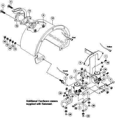
RATED LOAD LIMITER
DC 34,9 PARTS DRAWING
15
DC 34,9 PARTS LIST
Item # |
Qty |
Part No. |
Description |
Item # |
Qty |
Part No. |
Description |
1 |
1 |
251110 |
SWITCH ASSY-12FT LG |
41 |
10 |
418177 |
LOCKWASHER-3/8 MED SECT, Z/P |
|
|
282032 |
HEAVY DUTY SWITCH ASSY-12FT LG (OPT. NOT S |
42 |
2 |
438014 |
DRAG BRAKE |
2 |
1 |
282067 |
E-STOP SWITCH KIT (12V) (NOT SHOWN) |
43 |
2 |
442184 |
GASKET |
|
1 |
282068 |
E-STOP SWITCH KIT (24V) (NOT SHOWN) |
44 |
1 |
442185 |
GASKET |
3 |
1 |
262039 |
MOTOR (12V) |
45 |
1 |
442205 |
GASKET |
|
1 |
262038 |
MOTOR (24V) |
46 |
|
|
|
4 |
1 |
276056 |
SHIFTER ASSEMBLY |
47 |
1 |
340023 |
KEY |
5 |
1 |
278028 |
SOLENOID ASSEMBLY (24V) |
48 |
2 |
450006 |
BARTH KEY |
|
1 |
278170 |
SOLENOID ASSEMBLY (12V) |
49 |
4 |
450016 |
BARTH KEY |
6 |
1 |
289015 |
ASSEMBLY-WIRE, BATTERY CABLE, RED |
50 |
1 |
456001 |
LUBE FITTING |
7 |
1 |
289141 |
ASSEMBLY-WIRE, GROUND, BLACK |
51 |
2 |
456008 |
RELIEF FITTING |
8 |
1 |
434568 |
NAME AND DATA PLATE |
52 |
|
|
|
9 |
1 |
324160 |
JAW CLUTCH |
53 |
2 |
468002 |
REDUCER |
10 |
1 |
328106 |
COVER - SPUR GEAR HOUSING |
54 |
2 |
468011 |
PIPE PLUG |
11 |
1 |
328134 |
COVER - GEAR HOUSING |
55 |
2 |
468017 |
PIPE PLUG |
12 |
1 |
332550 |
DRUM ASSEMBLY (STD) 332255 ("Y" DRUM ASSY) |
56 |
1 |
468018 |
PIPE PLUG |
13 |
1 |
334001 |
IDLER GEAR |
57 |
2 |
470001 |
DOWEL PIN |
14 |
2 |
334003 |
SPUR GEAR |
58 |
1 |
470033 |
SPIROL PIN |
15 |
1 |
334129 |
PINION GEAR |
59 |
1 |
472012 |
PLUG |
16 |
1 |
334161 |
GEAR R.H. - 60:1 334163 GEAR RH - 46:1 |
60 |
1 |
472013 |
PLUG |
17 |
1 |
336010 |
SHIFTER HANDLE |
61 |
1 |
482013 |
BOOT |
18 |
1 |
338203 |
HOUSING-SPUR GEAR |
62 |
1 |
486009 |
OIL SEAL |
19 |
1 |
338208 |
HOUSING-CLUTCH |
63 |
1 |
486017 |
OIL SEAL |
20 |
1 |
338273 |
HOUSING-GEAR |
64 |
1 |
486023 |
OIL SEAL |
21 |
1 |
342033 |
KEY |
65 |
1 |
490003 |
SNAP RING |
22 |
1 |
356901 |
SHAFT-SPUR |
66 |
2 |
494002 |
SPRING |
23 |
1 |
357479 |
SHAFT-DRUM (STD) |
67 |
1 |
494053 |
SPRING |
|
1 |
357481 |
SHAFT DRUM "Y" |
68 |
3 |
518002 |
THRUST WASHER |
25 |
1 |
368001 |
WORM-R.H. - 60:1 368019 WORM R-H 46:1 |
69 |
1 |
518014 |
THRUST WASHER |
26 |
2 |
402002 |
BALL BEARING |
70 |
2 |
518015 |
THRUST WASHER |
27 |
4 |
412003 |
BUSHING |
71 |
|
|
|
28 |
3 |
402001 |
BUSHING |
72 |
1 |
282064 |
SWITCH ASSEMBLY |
29 |
1 |
412045 |
BUSHING |
73 |
1 |
316093 |
BEARING CAP |
30 |
12 |
414038 |
CAPSCREW-1/4-20NC X 3/4, HXHD,GR-5,Z/P |
74 |
4 |
414857 |
CAPSCREW |
31 |
9 |
414045 |
CAPSCREW-1/4-20NC X 1 HXHD, GR-5, Z/P |
75 |
2 |
416003 |
SETSCREW |
32 |
3 |
414059 |
CAPSCREW-1/4-20NC X 1 GR-5 HXHD Z/P |
76 |
1 |
462039 |
O-RING |
33 |
1 |
414279 |
CAPSCREW-3/8-16NC X 3/4 HX HD GR-5 |
77 |
1 |
518034 |
THRUST ACTUATOR |
34 |
4 |
414845 |
CAPSCREW-1/4-20NC X 1 HXSOCHD, NYLOK |
78 |
5 |
518035 |
THRUST DISC |
35 |
2 |
414856 |
CAPSCREW-1/4-20NC X 3/4 HXSOCHD Z/P |
79 |
1 |
302808 |
ANGLE (STD) |
36 |
|
|
|
|
1 |
302811 |
ANGLE (Y) |
37 |
1 |
416030 |
SETSCREW-1/4-20 X 3/8 HX SOC FULL DOG PT. |
80 |
1 |
302809 |
ANGLE (STD) |
38 |
1 |
315008 |
ROPE ANCHOR |
|
1 |
302810 |
ANGLE (Y) |
39 |
3 |
418040 |
NUT-3/8-24NF HEX REG Z/P |
81 |
6 |
414282 |
CAPSCREW- 3/8-16NC X 1 1/4 LG HX HD Z/P GR5 |
40 |
3 |
418154 |
WASHER-1/4 FLAT ALUM. |
82 |
1 |
414912 |
CAPSCREW 3/8-16NC X 5/8 LG SOC HD |
Solenoid Assembly Parts
278027 - 12V
278028 - 24V
Item No |
Qty |
Part No. |
Description |
|
|
|
|
1 |
1 |
280013 |
Cable & Bolt Assy (12 V) |
|
1 |
280009 |
Cable & Bolt Assy (24 V) |
2 |
1 |
289091 |
Wire Assembly |
3 |
3 |
289167 |
Wire Assembly (12) |
|
3 |
289077 |
Wire Assembly (24) |
4 |
2 |
364001 |
Copper Strap |
5 |
2 |
364002 |
Copper Strap |
6 |
1 |
408035 |
Solenoid Bracket |
7 |
2 |
416216 |
Screw #10-24NC X 1/2”, Round Head Slotted zinc |
8 |
2 |
416227 |
Screw #10-24NC X 3/4”, Truss Cross-recess black |
9 |
4 |
418004 |
Nut #10-24NC zin |
10 |
2 |
418022 |
Nut 5/16-18NC zi |
11 |
2 |
418140 |
Flat Washer #10 |
12 |
2 |
418141 |
Lockwasher #10 |
13 |
1 |
418163 |
Lockwasher 5/16 |
14 |
1 |
418164 |
Shake-proof Washer 5/16 Internal Teeth zinc |
15 |
1 |
418165 |
Shake-proof Washer 5/16 External Teeth zinc |
16 |
1 |
430013 |
Female Connector |
17 |
2 |
440071 |
Terminal-Tab |
18 |
2 |
440110 |
Solenoid (12V) |
|
2 |
440114 |
Solenoid (24V) |
19 |
1 |
472071 |
Solenoid Cover |
20 |
1 |
482029 |
Cover-Connector |
16
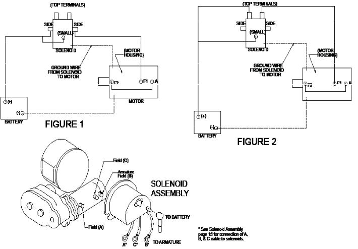
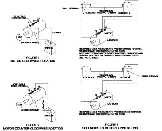
TEST PROCEDURE FOR SOLENOIDS
Steps to follow when testing current flow through DC solenoids.
It should be noted that when testing a 12 volt or 24 volt solenoid, the DC motor and battery must be of the same voltage.
To test the solenoids: (See Figure 1).
1.Securely clamp a motor to a bench or work surface.
2.Attach a #6 gauge jumper wire from “A” terminal on the motor to one of the field terminals on the motor, (F-2).
3.Attach the other motor field terminal (F-1) to one of the side terminals of the solenoid.
4.Ground the solenoid to the motor with a wire as shown.
5.Attach positive (+) battery wire to the opposite side terminal of solenoid. Ground the negative (-) battery wire to the motor housing.
6.Touch “hot” wire, from the positive battery terminal, to small terminal of the solenoid.
7.The motor should now be running if the solenoid is good. If not, make sure the motor will run directly from the battery. (See motor test procedure, Page 17).
8.To test the upper contacts use the same hookup except use the top terminals. (See Figure 2). When hooked up as shown in Figure 2, motor should start running.
When the “hot” wire is touched to the small terminal the motor will stop operating.
The top terminals are normally closed; i.e. connected, and the side terminals open, or not connected. When the solenoid operates, the top terminals are disconnected and the side terminals are connected.
Take care not to bring “hot” wires into contact with ground in order to prevent electrical arcing.
17
TEST PROCEDURE FOR MOTOR
The Ramsey Winch motor is a (4 pole-4 coil) series wound 12 volt or 24 volt DC motor.
The 4 pole-4 coil feature provides high torque at low speeds.
To test the motor to determine if it is functioning properly, first securely fasten the motor to a bench or work surface so it will not jump or move around during test procedure (the starting torque of motor is high).
1.Connect a jumper wire (at least a number 6 wire) from F-1 to “A” motor terminals (See Figure 1)
2.Attach a wire (at least a number 6 wire) from positive
(+) battery terminal to F-2 motor terminal. Ground negative (-) battery terminal to motor housing (See Figure 1). Motor should now run.
To reverse the direction of rotation:
1.Attach jumper wire from F-2 to “A” motor terminals (See Figure 2).
2.Attach wire from positive (+) battery terminal to F-1 motor terminal. Ground negative (-) battery terminal to motor housing (See Figure 2).
NOTE: Always attach battery wire solidly to motor terminals. Make and break the connection of the negative (-) battery terminal at the motor housing. This avoids burning the motor terminals.
CAUTION: DO NOT RUN THE MOTOR FOR A LONG PERIOD OF TIME IN FASHION MENTIONED ABOVE, BECAUSE THE MOTOR COULD BECOME DAMAGED.
The motor running idle on the bench will draw 55 amperes and must run free and easy. If the ampere draw is more than 60 amperes and the motor runs rough or has a strange sound, it should be replaced.
With the motor attached in place on a winch (less cable on drum) the ampere draw should be approximately 65 to 70 amperes.
If after following the procedure outlined, the test on the winch significantly exceeds 70 amperes, refer to your Owner’s Manual for trouble shooting suggestions on the mechanical portion of the winch.
See Figure 3 for the solenoids connection to the motor and the battery.
18
MANUEL D’EXPLOITATION, DE
DÉPANNAGE ET
D’ENTRETIEN
English (Original Instructions) .. . . . . . . . . . . . . . . 1
Français (Traduction des instructions originales) 19
Deutsch (Übersetzung der Originalanleitung) . . . . 37
Español (Traducción de las instrucciones originales)55
TREUILS INDUSTRIELS BAS
ÉQUIPÉS RAM-LOK®, MODÈLE DC 34,9
MISE EN GARDE : ASSUREZ-VOUS DE LIRE ET DE COMPRENDRE CE MANUEL AVANT D’INSTALLER ET D’UTILISER LE TREUIL. LISEZ LES AVERTISSEMENTS !
UTILISATION PRÉVUE : DÉPANNAGE DE VÉHICULE ET TRACTION DE CHARGES
Ramsey Winch Company
P.O. Box 581510 - Tulsa, OK 74158-1510 USA
Téléphone : +1-(918) 438-2760 - Télécopieur : +1-(918) 438-6688 Nous visiter à http://www.ramsey.com
Ramsey Représentant autorisé dans la comuauté:
(Veuillez prendre contact uniquement pour des questions réglementaires.)
Alura Group BV
P.O. Box 18626
2502 EP The Hague
The Netherlands
Tel: (31) (0) 70 362-4896
Fax: (31) (0) 70 346-7299
OM-914219-1012-C
TABLE DES MATIÈRES
RESPONSABILITÉ DE L’UTILISATEUR POUR CONFORMITÉ AUX NORMES CE . . . . . . . . . . . . . . . . . . . . . . . . 21 CARACTÉRISTIQUES TECHNIQUES. . . . . . . . . . . . . . . . . . . . . . . . . . . . . . . . . . . . . . . . . . . . . . . . . . . . . . . . . 21 AVERTISSEMENTS . . . . . . . . . . . . . . . . . . . . . . . . . . . . . . . . . . . . . . . . . . . . . . . . . . . . . . . . . . . . . . . . . . . . . 21 FIXATION DU TREUIL . . . . . . . . . . . . . . . . . . . . . . . . . . . . . . . . . . . . . . . . . . . . . . . . . . . . . . . . . . . . . . . . . . . 21 POSE DU CÂBLE. . . . . . . . . . . . . . . . . . . . . . . . . . . . . . . . . . . . . . . . . . . . . . . . . . . . . . . . . . . . . . . . . . . . . . . 22 TECHNIQUES D’UTILISATION . . . . . . . . . . . . . . . . . . . . . . . . . . . . . . . . . . . . . . . . . . . . . . . . . . . . . . . . . . . . . 22 ENTRETIEN DU TREUIL. . . . . . . . . . . . . . . . . . . . . . . . . . . . . . . . . . . . . . . . . . . . . . . . . . . . . . . . . . . . . . . . . . 22 BRANCHEMENTS ÉLECTRIQUES . . . . . . . . . . . . . . . . . . . . . . . . . . . . . . . . . . . . . . . . . . . . . . . . . . . . . . . . . . 23 RÉGLAGE DU LIMITEUR À CHARGE NOMINALE . . . . . . . . . . . . . . . . . . . . . . . . . . . . . . . . . . . . . . . . . . . . . . . 23 FIN DE LA PROCÉDURE D’ENTRETIEN . . . . . . . . . . . . . . . . . . . . . . . . . . . . . . . . . . . . . . . . . . . . . . . . . . . . . . 23 GUIDE DE RÉSOLUTION DES PROBLÈMES . . . . . . . . . . . . . . . . . . . . . . . . . . . . . . . . . . . . . . . . . . . . . . . . . . . 24 INSTRUCTIONS DE RÉVISION
DÉMONTAGE . . . . . . . . . . . . . . . . . . . . . . . . . . . . . . . . . . . . . . . . . . . . . . . . . . . . . . . . . . . . . . . . . . . . . . . 2 -2 REMONTAGE . . . . . . . . . . . . . . . . . . . . . . . . . . . . . . . . . . . . . . . . . . . . . . . . . . . . . . . . . . . . . . . . . . . . . . . 28PLAN CÔTÉ . . . . . . . . . . . . . . . . . . . . . . . . . . . . . . . . . . . . . . . . . . . . . . . . . . . . . . . . . . . . . . . . . . . . . . . . . . 3 LISTE ET SCHÉMA DES PIÈCES . . . . . . . . . . . . . . . . . . . . . . . . . . . . . . . . . . . . . . . . . . . . . . . . . . . . . . . . . 3 -3 LISTE DES PIÈCES DU SOLÉNOÏDE. . . . . . . . . . . . . . . . . . . . . . . . . . . . . . . . . . . . . . . . . . . . . . . . . . . . . . . . . 3 TEST DES SOLÉNOÏDES . . . . . . . . . . . . . . . . . . . . . . . . . . . . . . . . . . . . . . . . . . . . . . . . . . . . . . . . . . . . . . . . . 3 TEST DU MOTEUR . . . . . . . . . . . . . . . . . . . . . . . . . . . . . . . . . . . . . . . . . . . . . . . . . . . . . . . . . . . . . . . . . . . . . 3
*CARACTÉRISTIQUES TECHNIQUES :
Plage de température ambiante |
|
|
|
-28 °C à 60 °C (-20 °F à 140 °F) |
|
|||||||||
Niveau sonore |
|
|
|
|
|
|
|
|
|
|
80db |
|
||
COUCHE DE CÂBLE |
|
|
|
|
1 |
|
|
2 |
|
|
3 |
|
|
|
Traction nominale par couche de |
|
kN |
|
34,9 |
|
28,9 |
|
24,9 |
|
|
||||
câble |
|
lb |
|
7,840 |
|
6,500 |
|
5,600 |
|
|
||||
Capacité cumulative de câble par |
|
m |
|
7 |
|
|
16 |
|
|
28 |
|
|
|
|
couche (long tambour) |
|
pi |
|
25 |
|
|
55 |
|
|
95 |
|
|
|
|
Capacité cumulative de câble par |
|
m |
|
3 |
|
|
9 |
|
|
15 |
|
|
|
|
couche (tambour court) |
|
pi |
|
10 |
|
|
30 |
|
|
50 |
|
|
|
|
|
|
|
|
|
|
|
|
|
|
|
||||
Traction du câble, |
kN |
|
À vide |
|
8,8 |
|
17,7 |
|
34,9 |
|||||
|
|
|
|
|
|
|
|
|
|
|
|
|||
première couche |
lb |
|
|
2,000 |
|
4,000 |
|
7,840 |
||||||
|
|
|
|
|
|
|||||||||
|
|
|
|
|
|
|
|
|
|
|||||
* DC 34,9 et DCY 34,9 |
m/min |
|
4,3 |
|
2,1 |
|
1,5 |
|
1,7 |
|||||
Vitesse du câble, première |
|
|
|
|
|
|
|
|
|
|
|
|
|
|
pi/min |
|
14 |
|
7 |
|
5 |
|
3,5 |
||||||
couche 12 V et 24 V |
|
|
|
|
||||||||||
* Intensité du moteur DC |
12V |
|
65 |
|
110 |
|
180 |
|
370 |
|||||
|
|
|
|
|
|
|
|
|
|
|
|
|
|
|
34,9 et DCY 34,9 |
24V |
|
30 |
|
50 |
|
90 |
|
140 |
|||||
|
|
|
|
|
||||||||||
|
|
|
|
|
|
|
|
|
|
|
|
|
|
|
* Ces caractéristiques techniques sont basées sur l’utilisation du câble métallique recommandé de 10 mm (0,393 po) de calibre 1960.
AVERTISSEMENTS :
L’UTILISATEUR DOIT VEILLER À CE QUE TOUT OPÉRATEUR REÇOIVE LA FORMATION NÉCESSAIRE. L’OPÉRATEUR DOIT TOUJOURS TRAVAILLER EN CONFORMITÉ AVEC LES INSTRUCTIONS D’UTILISATION. L’EMBRAYAGE DOIT ÊTRE COMPLÈTEMENT ENCLENCHÉ AVANT DE DÉMARRER LE TREUIL.
NE RELÂCHEZ JAMAIS L’EMBRAYAGE EN PRÉSENCE D’UNE CHARGE. NE JAMAIS SE PLACER SOUS UNE CHARGE SOULEVÉE NI À PROXIMITÉ.
RESTEZ À L’ÉCART DU CÂBLE LORS DU TREUILLAGE. N’ESSAYEZ PAS DE GUIDER LE CÂBLE. N’UTILISEZ PAS LE TREUIL POUR SOULEVER, MAINTENIR OU TRANSPORTER DES PERSONNES.
IL CONVIENT DE CONSERVER AU MINIMUM DEUX TOURS DE CÂBLE AUTOUR DU TAMBOUR POUR MAINTENIR LA CHARGE.
ÉVITEZ TOUTE SITUATION DE DÉPLACEMENT DE LA CHARGE OU D’À-COUPS. ÉVITEZ LES MOUVEMENTS SACCADÉS.
Responsabilité de l’utilisateur pour conformité aux normes CE
1.Montez le treuil comme dans les instructions d’installation.
2.Installez le commutateur d’arrêt d’urgence comme dans les instructions d’installation comprises dans le kit de dispositif d’arrêt d’urgence.
3.Installez 10 mm (0,393 po) de câble métallique de calibre 1960. Longueur maximale de câble de 28 m (95 pi) pour trois couches maximum.
4.Attachez le câble au tambour comme indiqué dans les Instructions d’installation du câble.
5.Utilisez un crochet comportant un loquet de sécurité et une charge de rupture maximale de 87 kN.
21
FIXATION DU TREUIL
Ce treuil doit absolument être monté correctement afin que les trois principales parties soient alignées (l’extrémité du carter d’embrayage, le tambour du câble et l’extrémité de la boîte d’engrenages).
Tous les modèles standard de treuil DC 34,9 sont fournis avec des cornières de montage recommandées. Ces cornières mesurent 9 x 63 x 63 x 914 mm (3/8 x 2-1/2 x 2-1/2 x 36 po) et sont fabriquées en acier haute résistance, soit 344 500 KPa (50 000 PSI).
POSE DU CÂBLE
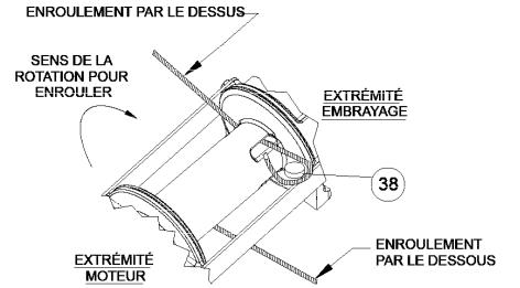
1. Déroulez le câble sur le sol pour éviter qu’il ne se torde. Recouvrez bien l’extrémité du câble opposée au crochet avec un r uban adhésif plastique ou de type équivalent pour éviter qu’il ne s’effiloche.
2.Insérez le câble dans la partie étroite du logement, contre la collerette du tambour. Enroulez le câble autour du galet d’a ncrage (pièce no
38)et rentrez les deux dans l’extrémité large du logement. Utilisez un marteau-caoutchouc pour acheminer l’arrière du câble, e n le plaçant fermement avec le galet d’ancrage dans le logement.
3.Faites tourner avec précaution le treuil dans le sens de l’enroulement. Maintenez une tension sur l’extrémité du câble et e nroulez tout le câble sur le tambour en veillant à former des couches régulières.
TECHNIQUES D’UTILISATION
L’enroulement irrégulier du câble lors de la traction d’une charge ne présente pas de problème sauf en cas d’accumulation du câble sur un côté du tambour. Dans ce cas, inversez le fonctionnement du treuil afin de soulager la charge et déplacez votre point d’attache vers le centre du véhicule. Une fois le travail terminé, vous pouvez dérouler le câble et l’enrouler à nouveau d’une manière régulière.
S’il existe le moindre risque de rupture du câble lors de la traction d’une charge, placez une couverture, une veste ou une bâche sur le câble à environ 1,8 m (6 pi) du crochet. Ceci devrait ralentir le retour du câble en cas de rupture et réduire les risques de blessures graves.
Contrôlez le niveau d’huile du treuil tous les six mois. Remplacez l’huile tous les ans ou plus souvent en cas d’utilisation fréquente. Utilisez 0,35 l (0,75 pinte) d’huile E.P. 140 polyvalente dans la boîte de la vis sans fin et 0,23 l (0,5 pinte) de SAE 20 dans la boîte d’engrenages Si l’huile est souillée par des particules métalliques, examinez le treuil afin de déceler tout signe d’usure anormale.
Vérifiez régulièrement tous les branchements électriques et tous les boulons de fixation. Serrez les pièces si besoin est.
La caractéristique minimale d’ampère-heure de la batterie du véhicule doit être de 70 et celle-ci doit être utilisée avec un alternateur d’au moins 40 ampères. Il est conseillé de disposer d’une batterie de secours pour fournir une alimentation supplémentaire.
Inspectez fréquemment le câble. Tout câble effiloché ou comportant des brins brisés doit être remplacé immédiatement. L’embrayage semi-automatique RAM-LOK® permet un déroulement rapide du câble à partir du tambour afin de le fixer à une charge. L’embrayage s’actionne comme indiqué ci-dessous au moyen de la poignée en forme de T qui se trouve à l’extrémité du treuil.
1.POUR RELÂCHER L’EMBRAYAGE, faites fonctionner le treuil en marche arrière (déroulement) jusqu’à ce que la charge ne porte plus sur le câble. Tirez la poignée d’embrayage vers l’extérieur, faites-la tourner de 90º dans le sens inverse des aiguilles d’une montre, puis relâchez-la. L’embrayage est alors supprimé et le câble peut être tiré à la main.
2.POUR ENCLENCHER L’EMBRAYAGE, tirez la poignée vers l’extérieur, faites-la tourner de 90º dans le sens des aiguilles d’une montre et relâchez-la. Faites tourner le treuil en marche arrière jusqu’à ce que sa poignée se réenclenche complètement ou que le tambour commence à tourner. À ce point, assurez-vous que la poignée est complètement rentrée. Il est possible de retirer le bouchon en plastique du haut afin de vérifier si l’embrayage est bien enclenché. Une fois l’embrayage entièrement réenclenché, le treuil est prêt à enrouler le câble.
22
 Loading...