


OPERATING, SERVICE
AND MAINTENANCE
MANUAL
English . . . . . . . . . . . . . . . . . . . .1
Français . . . . . . . . . . . . . . . . . .21
Deutsch . . . . . . . . . . . . . . . . . . .41
Español . . . . . . . . . . . . . . . . . . .62
MODEL DC-200 SERIES
RAM-LOK® EQUIPPED
INDUSTRIAL LOW-MOUNT WINCHES
INCLUDES: DC-200/DC-246, DC-24-200/DC-24-246, DCY-200/DCY-246, DCY-24-200/DCY-24-246 AND MODELS EQUIPPED WITH
OPTIONAL ADJUSTABLE, AUTOMATIC OIL COOLED SAFETY BRAKE:
DCG-200, DCYG-200 SERIES WINCHES.
CAUTION: READ AND UNDERSTAND THIS MANUAL BEFORE INSTALLATION AND OPERATION OF WINCH. SEE SAFEGUARDS AND WARNINGS!
Ramsey Winch Company
P.O. Box 581510 - Tulsa, OK 74158-1510 USA
Phone: (918) 438-2760 - Fax (918) 438-6688
Visit us at http://www.ramsey.com
OM-914190-0309-C

TABLE OF CONTENTS
INTRODUCTION . . . . . . . . . . . . . . . . . . . . . . . . . . . . . . . . . . . . . . . . . . . . . . . . . . . . . . . . . . . . . . . . . . . . . . . . .3 WARRANTY INFORMATION . . . . . . . . . . . . . . . . . . . . . . . . . . . . . . . . . . . . . . . . . . . . . . . . . . . . . . . . . . . . . . . .3 SPECIFICATION . . . . . . . . . . . . . . . . . . . . . . . . . . . . . . . . . . . . . . . . . . . . . . . . . . . . . . . . . . . . . . . . . . . . . . . . .3 WARNINGS . . . . . . . . . . . . . . . . . . . . . . . . . . . . . . . . . . . . . . . . . . . . . . . . . . . . . . . . . . . . . . . . . . . . . . . . . . . .3 TECHNIQUES OF OPERATION . . . . . . . . . . . . . . . . . . . . . . . . . . . . . . . . . . . . . . . . . . . . . . . . . . . . . . . . . . . . . .4 CABLE INSTALLATION . . . . . . . . . . . . . . . . . . . . . . . . . . . . . . . . . . . . . . . . . . . . . . . . . . . . . . . . . . . . . . . . . . . .4 WINCH MAINTENANCE . . . . . . . . . . . . . . . . . . . . . . . . . . . . . . . . . . . . . . . . . . . . . . . . . . . . . . . . . . . . . . . . . . .5 WINCH MOUNTING . . . . . . . . . . . . . . . . . . . . . . . . . . . . . . . . . . . . . . . . . . . . . . . . . . . . . . . . . . . . . . . . . . . . . .5 ELECTRICAL CONNECTIONS . . . . . . . . . . . . . . . . . . . . . . . . . . . . . . . . . . . . . . . . . . . . . . . . . . . . . . . . . . . . . . .5 ADJUSTING THE OIL COOLED SAFETY BRAKE . . . . . . . . . . . . . . . . . . . . . . . . . . . . . . . . . . . . . . . . . . . . . . . . .6 SERVICING OF THE OIL COOLED SAFETY BRAKE . . . . . . . . . . . . . . . . . . . . . . . . . . . . . . . . . . . . . . . . . . . . . . .6 RE-ASSEMBLING AND CHECKING THE BRAKE . . . . . . . . . . . . . . . . . . . . . . . . . . . . . . . . . . . . . . . . . . . . . . . . .7 TEST FOR PROPER BRAKE ASSEMBLY . . . . . . . . . . . . . . . . . . . . . . . . . . . . . . . . . . . . . . . . . . . . . . . . . . . . . . .7
INSTRUCTIONS FOR CHECKING ASSEMBLY
ARRANGEMENT AND SETTING OF WORM BRAKE . . . . . . . . . . . . . . . . . . . . . . . . . . . . . . . . . . . . . . . . . . .7 TROUBLE SHOOTING GUIDE . . . . . . . . . . . . . . . . . . . . . . . . . . . . . . . . . . . . . . . . . . . . . . . . . . . . . . . . . . . . . . .8
INSTRUCTIONS FOR OVERHAUL OF
RAMSEY MODEL DC-200 SERIES RAM-LOK® WINCHES
DISASSEMBLY . . . . . . . . . . . . . . . . . . . . . . . . . . . . . . . . . . . . . . . . . . . . . . . . . . . . . . . . . . . . . . . . . . . . . . .9-12 REASSEMBLY . . . . . . . . . . . . . . . . . . . . . . . . . . . . . . . . . . . . . . . . . . . . . . . . . . . . . . . . . . . . . . . . . . . . . . .12-13 DIMENSIONAL DRAWING . . . . . . . . . . . . . . . . . . . . . . . . . . . . . . . . . . . . . . . . . . . . . . . . . . . . . . . . . . . . . . . .14 PARTS LIST AND PARTS DRAWING . . . . . . . . . . . . . . . . . . . . . . . . . . . . . . . . . . . . . . . . . . . . . . . . . . . . . .15-17 SOLENOID AND SWITCH ASSEMBLY PARTS LIST . . . . . . . . . . . . . . . . . . . . . . . . . . . . . . . . . . . . . . . . . . . . . .18 TEST PROCEDURE FOR SOLENOID . . . . . . . . . . . . . . . . . . . . . . . . . . . . . . . . . . . . . . . . . . . . . . . . . . . . . . . . .19 TEST PROCEDURE FOR MOTOR . . . . . . . . . . . . . . . . . . . . . . . . . . . . . . . . . . . . . . . . . . . . . . . . . . . . . . . . . . .20
LIMITED WARRANTY
RAMSEY WINCH warrants each new RAMSEY Winch to be free from defects in material and workmanship for a period of one (1) year from date of purchase.
The obligation under this warranty, statutory or otherwise, is limited to the replacement or repair at the Manufacturer's factory, or at a point designated by the Manufacturer, of such part that shall appear to the Manufacturer, upon inspection of such part, to have been defective in material or workmanship.
This warranty does not obligate RAMSEY WINCH to bear the cost of labor or transportation charges in connection with the replacement or repair of defective parts, nor shall it apply to a product upon which repair or alterations have been made, unless authorized by Manufacturer, or for equipment misused, neglected or which has not been installed correctly.
RAMSEY WINCH shall in no event be liable for special or consequential damages. RAMSEY WINCH makes no warranty in respect to accessories such as being subject to the warranties of their respective manufacturers.
RAMSEY WINCH, whose policy is one of continuous improvement, reserves the right to improve its products through changes in design or materials, as it may deem desirable without being obligated to incorporate such changes in products of prior manufacture.
If field service at the request of the Buyer is rendered and the fault is found not to be with RAMSEY WINCH's product, the Buyer shall pay the time and expense to the field representative. Bills for service, labor or other expenses that have been incurred by the Buyer without approval or authorization by RAMSEY WINCH will not be accepted. See warranty card for details.

RAMSEY ELECTRICAL WINCH MODEL DC-200 SERIES
PLEASE READ THIS MANUAL CAREFULLY.
This manual contains useful ideas in obtaining the most efficient operation from your Ramsey Winch, and safety procedures one needs to know before operating a Ramsey Winch.
WARRANTY INFORMATION
Ramsey Winches are designed and built to exacting specifications. Great care and skill go into every winch we make. If the need should arise, warranty procedure is outlined on the back of your self-addressed postage paid warranty card. Please read and fill out the enclosed warranty card and send it to Ramsey Winch Company. If you have any problems with your winch, please follow instructions for prompt service on all warranty claims.
* SPECIFICATIONS: Conforms to SAE J706**
Rated Line Pull |
lbs. |
………………………………………………………………… |
8,000 |
|||
1st Layer |
Kg. |
………………………………………………………………… |
3,620 |
|||
|
|
|
||||
Total Gear |
DC-200 ………………………………………………………………… |
470 |
||||
Reduction |
DC-246 ………………………………………………………………… |
360 |
||||
|
|
|
||||
Weight: |
DC-200/DC-246 (long drum).…………………………………………… |
116 lbs (52.7 Kg) |
||||
DCY-200/DCY-246 (short drum).………………………………………… |
105 lbs (47.6 Kg.) |
|||||
|
||||||
|
|
|||||
|
|
|||||
MAXIMUM GEAR BOX OIL TEMPERATURE SHOULD NOT EXCEED………………………….. |
250° F (121° C) |
|||||
|
|
|
|
|
|
|
|
|
|
|
|
|
|
LAYER OF CABLE |
|
1 |
2 |
3 |
4 |
|
|
|
|
|
|
|
|
* Rated line pull |
lbs. |
8,000 |
6,700 |
5,700 |
5,000 |
|
per layer |
Kg. |
3,620 |
3,030 |
2,580 |
2,260 |
|
|
|
|
|
|
|
|
Long Drum Cable |
ft. |
25 |
60 |
95 |
140 |
|
Capacity per Layer |
m |
7 |
18 |
28 |
42 |
|
|
|
|
|
|
|
|
Short Drum Cable |
ft. |
15 |
30 |
55 |
75 |
|
Capacity per Layer |
m |
4 |
9 |
16 |
22 |
|
|
|
|
|
|
|
|
Line Speed |
FPM |
15 |
30 |
55 |
75 |
|
MPM |
4 |
9 |
16 |
22 |
||
|
||||||
|
|
|
|
|
|
|
* These specifications are based on recommended 3/8 inch (9.5 mm) diameter extra improved plow steel (EIPS) wire rope or equivalent.
** Winch only comforms to SAE J706. For SAE qualifications for mounting angles, if applicable, consult Ramsey Engineering.
NOTE: The rated line pulls shown are for the winch only. Consult wire rope manufacturer for wire rope ratings.
 WARNINGS
CLUTCH MUST BE TOTALLY ENGAGED BEFORE STARTING THE WINCHING OPERATION. DO NOT DISENGAGE CLUTCH UNDER LOAD.
DO NOT LEAVE CLUTCH ENGAGED WHEN WINCH IS NOT IN USE.
STAY OUT FROM UNDER AND AWAY FROM RAISED LOADS.
STAND CLEAR OF CABLE WHILE PULLING. DO NOT TRY TO GUIDE CABLE.
DO NOT EXCEED MAXIMUM LINE PULL RATINGS SHOWN IN TABLE.
DO NOT USE WINCH TO LIFT, SUPPORT, OR OTHERWISE TRANSPORT PERSONNEL.
A MINIMUM OF 5 WRAPS OF CABLE AROUND THE DRUM BARREL IS NECESSARY TO HOLD THE LOAD. CABLE CLAMP IS NOT DESIGNED TO HOLD LOAD.
DISCONNECT THE REMOTE CONTROL SWITCH FROM WINCH WHEN NOT IN USE.
3
TECHNIQUES OF OPERATION
The best way to get acquainted with how your winch operates is to make test runs before you actually use it. Plan your test in advance. Remember, you hear your winch, as well as see it operate. Get to recognize the sounds of a light steady pull, a heavy pull, and sounds caused by load jerking or shifting. Gain confidence in operating your winch and its use will become second nature with you.
The uneven spooling of cable, while pulling a load, is not a problem, unless there is a cable pileup on one end of drum. If this happens, reverse the winch to relieve the load and move your anchor point further to the center of the vehicle. After the job is done you can unspool and rewind for a neat lay of the cable
When pulling a load where there is even a remote chance of cable failure, place a blanket, jacket or tarpaulin over the cable about six feet behind the hook. This will slow the snap back of a broken cable and could prevent serious injury.
Check oil level of winch every six months. Replace oil annually or more often if winch is used frequently. Use 0.75 pint (0.35 L) of all purpose E.P. 140 oil in the worm gear housing and 0.5 pint (0.23 L) SAE 20 for spur gear box. If the oil is contaminated with metallic particles, inspect winch for cause of abnormal wear.
Periodically check all electrical connections and mounting bolts. Tighten hardware if necessary.
The minimum ampere-hour rating of vehicle battery should be 70, and used with at least a 40 ampere alternator. An auxiliary battery is recommended to supply additional battery power.
Inspect the cable frequently. If the cable becomes frayed with broken strands, replace immediately. Cable and hook assembly may be purchased from a Ramsey distributor.
The RAM-LOK® semi-automatic clutch allows rapid unspooling of the cable, from cable drum, for hooking onto a load. The clutch is operated by the "T-handle", located on the end of the winch, as follows:
1.TO DISENGAGE CLUTCH, run the winch in the reverse (reel out) direction until the load is off the cable. Pull outward on the clutch handle, rotate it counter-clockwise 90º and release. The clutch is now locked out and the cable may be pulled off by hand.
2.TO ENGAGE CLUTCH, pull outward on the handle, rotate it clockwise 90º and release. Run the winch in reverse until the clutch handle snaps fully in or until the cable drum starts turning. At this point make sure the clutch handle is all the way in. The plastic plug in top of clutch housing may be removed, for inspection of clutch to assure total engagement. After the clutch is fully engaged, the winch is ready for winching in the cable.
CABLE INSTALLATION
1.Unwind cable by rolling it out along the ground to prevent kinking. Securely wrap end of cable, opposite hook, with plastic or similar tape to prevent fraying.
2.Insert the end of cable, opposite hook end, into the 7/16" (11 mm) diameter hole in drum barrel. Secure cable to drum barrel, using setscrew furnished with winch. TIGHTEN SETSCREW SECURELY.
3.Carefully run winch in the "reel-in" direction. Keeping tension on end of cable, spool all the cable onto the cable drum, taking care to form neatly wrapped layers.
4
WINCH MAINTENANCE
Adhering to the following maintenance schedule will keep your winch in top condition and performing as it should with a minimum of repair.
A. |
WEEKLY |
1. |
Check the oil level and maintain it to the oil level plug. If oil is leaking out, determine location and repair. |
2. |
Check the pressure relief plug in top of the gear housing. Be sure that it is in good operating condition so that hot oil |
|
gasses may escape. |
3. |
Lubricate cable with light oil. |
B. |
MONTHLY |
1.Lubricate the various grease fittings located in the cable drum, end bearing, clutch housing or clutch operating linkage. Any good grade of moly-disulfide containing grease is acceptable.
2.Check the action of the sliding clutch, making sure it is fully engaging and disengaging with the cable drum. Remove the plastic plug in top of the housing and observe if the clutch is fully engaging. If clutch is not fully engaging, inspect clutch shifter assembly parts, check for damage or excessive wear and replace as necessary. Observe the jaws on both the clutch and cable drum, checking for rounding of the driving faces. If rounding has occurred they should be replaced immediately.
3.Check the winch mounting bolts. If any are missing, replace them and securely tighten any that are loose. Make sure to use only grade 5 bolts or better.
4.Check the torque setting of the oil cooled worm brake. Make any adjustments required, following the procedure described in ADJUSTING THE OIL COOLED WORM BRAKE in the Owner's Manual.
5.Check alignment of chain and sprockets and adjust as required to minimize wear.
6.Inspect the cable. If the cable has become frayed with broken strands, replace immediately.
C.ANNUALLY
1.Drain the oil from the winch annually or more often if winch is used frequently.
2.Fill the winch to the oil level plug with clean kerosene. Run the winch a few minutes with no load in the reel in direction. Drain the kerosene from the winch.
3.Refill the winch to the oil level plug with all purpose E.P. 140 gear oil.
4.Inspect frame and surrounding structure for cracks or deformation.
5.Gear wear can be estimated by rocking the drum back and forth and if necessary drain oil and remove cover for closer inspection.
WINCH MOUNTING
It is most important that this winch be mounted securely so that the three major sections (the clutch housing end, the cable drum and the gear housing end) are properly aligned.
All standard model DC-200 Series Winches are furnished with recommended mounting angles. Angle size is 1/4 x 2- 1/2 x 2-1/2 x 36" (6 x 63 x 63 x 914 mm) Lg. high strength (50,000 PSI [344,500 KPa] yield) steel angle.
ELECTRICAL CONNECTIONS
See dimensional drawing on Page 17. Using a power cable with appropriate end terminals, connect the positive (+) battery terminal to the 5/16" (8 mm) diameter stud on the plastic solenoid cover on the winch. IMPORTANT: Hold inner nut on stud with a wrench while tightening outer nut. Using a ground cable with appropriate end terminals, connect the negative (-) battery terminal to the 3/8" (9.5 mm) diameter winch mounting bolt nearest to the drum flange on the motor end of the winch. For distances up to 15 feet (5 M) from battery to winch, use #2 gauge wire for the above connections. For distances greater than 15 feet, use wire larger than #2 gauge.
5
ADJUSTING THE OIL COOLED WORM BRAKE
The oil-cooled, fully adjustable, automatic safety brake operates in the worm housing lubricant, all parts being submerged in oil. When the brake wears to the point that the load begins to drift, the brake can be adjusted as follows:
1.Loosen the lock nut on the adjusting screw.
2.Tighten the brake by turning the adjusting screw clockwise. CAUTION: Only 1/4 turn is usually required to adjust the brake. Over-tightening can cause overheating and damage to the brake parts. Tighten the lock nut after adjustment is completed.
If the brake does not respond to adjustment then a new leaf spring and brake disc is needed.
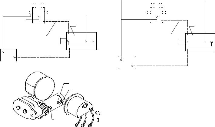
A torque wrench can be equipped with a special adapter to fit the input shaft (worm) of the winch. The adapter can be made by welding a nut to the end of a piece of tubing as shown in the following figure.
After welding the cap and nut to the tubing, slot the tubing as shown. This will allow the special adapter to slide over the keyway and will then act as a large socket. A torque wrench can then be used to apply the proper torque. Turn the torque wrench so that the drum turns in the spool out direction or lowering direction. The torque rating for the brake should be 13-18 ft-lbs. (17-24 Nm). If the torque wrench does not show the proper value as it turns, then the worm brake adjusting bolt should be turned clockwise 1/4 turn. Each time the adjusting bolt is turned, check the torque reading. Continue this procedure until the proper torque reading is achieved. Then tighten the lock nut.
TUBING
CAP
NUT
ADAPTER
SOCKET
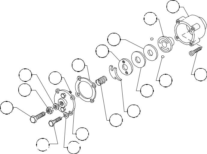
SERVICING OF THE OIL COOLED SAFETY BRAKE
1.Remove the drain plug and drain the worm gear oil from the worm housing.
2.Back off the jam nut, then the adjusting screw, both two turns or more by turning them counter-clockwise.
3.Remove the cover mounting screws.
4.Remove the cover along with coil spring and leaf spring.
5.Remove the retainer plate, composition brake disc, cam plate and balls. Note slots balls are in.
6.Inspect parts as follows:
a. Composition brake discs are |
|
|
|
|
BRAKE HOUSING |
|
1/8" (3 mm) thick when new. |
|
|
|
|
HUB |
|
Replace if thinner than 0.080" |
|
|
|
|
|
|
(2 mm) or if surfaces are |
|
|
|
|
CAM PLATE |
|
glazed or burnt. |
|
RETAINER PLATE |
|
|||
b. Inspect the flat, ground sur- |
|
|
GASKET |
|
||
face of the cam plate and |
THREAD SEAL |
PIN |
|
BALL |
||
retainer plate for glazing, |
|
|
||||
|
|
|
|
|||
JAM NUT |
|
|
|
COMPOSITION |
||
warpage, or other damage. |
|
|
|
|||
Glazing can be removed by |
|
|
|
|
BRAKE DISC |
|
ADJUSTING |
|
|
|
LEAF SPRING |
|
|
scraping carefully. |
|
|
|
|
||
SCREW |
|
|
|
|
||
|
|
|
COIL SPRING |
|
||
c. Inspect the leaf spring. It |
|
|
|
|
|
|
|
|
|
|
BRAKE COVER |
|
|
should be bowed 1/8" (3 mm). |
|
|
|
|
|
|
COVER |
|
|
|
|
||
|
|
|
|
VIEW |
||
|
MOUNTING |
|
||||
|
SCREW |
|
|
DIAGRAM 1 |
||
|
|
|
(LOOKING AT CAM |
|||
|
|
|
|
|
PLATE FROM WINCH) |
|
|
|
|
|
WORM BRAKE |
||
|
|
|
|
|
||
|
|
6 |
|
|
|
|
RE-ASSEMBLING AND CHECKING THE BRAKE
1.Press brake hub into place over worm shaft and key.
2.Assemble ball into appropriate slots of cam. (Refer to Diagram 1, Page 6). Use stiff grease to hold balls into place and slide cam over end of worm. Be sure that balls are secure, between cam slots and hub slots.
3.Install brake disc.
4.Install retainer plate, smooth side toward brake disc.
5.Install the gasket on the cover with a small amount of grease or sealer.
6.The coil spring goes over the adjusting screw on the inside of the cover.
7.Install the notches of the leaf spring on the pins protruding through the cover. The hollow side of the leaf spring goes toward the brake.
8.Install brake housing cover, making sure the protruding pins go through the leaf spring and into the holes in the retainer plate.
9.Bolt cover into place with the mounting screws. Install drain plug and add 1 pint all purpose E.P. 140 oil.
10.Turn winch in the hoisting direction at least one turn of the input shaft.
11.Turn the adjusting screw in until it is finger tight.
TEST FOR PROPER BRAKE ASSEMBLY
After the brake has been adjusted to the proper torque setting disengage clutch. Start vehicle engine and run winch in the reel in (hoisting direction). Allow winch to run in this direction for one minute.
Place your hand on the safety brake housing. If housing is not hot to the touch then run winch in the reverse direction (cable out) for one minute. Brake housing should begin to heat.
When these conditions exist, proper installation has been made. If heating becomes noticeable when running the winch in forward rotation (hoisting direction), the brake should be again disassembled. When disassembled, place the brake balls in the alternate set of slots in the cam plate, then carefully follow the instructions for re-assembling and checking the brake.
INSTRUCTIONS FOR CHECKING ASSEMBLY ARRANGEMENT AND SETTING OF WORM BRAKE
When the worm brake is assembled, the brake must be set with the balls in the #1 or the #2 set of cam slots. (View A-A, Page 6). It is indicated on the name plate whether the balls were installed in the #1 or the #2 slots at the factory.
Three factors determine which slots the balls should be in:
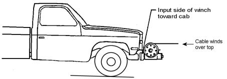
1.Direction cable winds on the drum. It normally WINDS OVER THE TOP of the drum barrel.
2.The cut of the gear set, right or left gear. The last letter in the model number of the winch, either R or L, designates right or left gear set. Example: R-20AR, R-30L, 700R, 800L.
3.The side of the winch that the input shaft is on. The INPUT SHAFT IN NORMALLY TOWARD THE CAB. Whether the winch has the gear box on the right or on the left side of the winch does not affect the brake setting.
EXAMPLE: When cable winds over the top of the drum, winch has a right cut gear and input shaft is toward the cab (diagram 2), then the balls need to be in the #2 cam slots.
If any one of these three factors differs from those stated above, the balls need to be in the #1 slots in the cam. A second change in these factors requires the original
arrangement, and if all three factors are different, the balls need to be in the #1 slots. (See Page 5 and 6 for disassembly and assembly instructions).
7 |
Diagram 2 |
TROUBLESHOOTING GUIDE
CONDITION |
|
POSSIBLE CAUSE |
|
CORRECTION |
CLUTCH INOPERATIVE OR |
1. Dry or rusted shaft. |
1. |
Clean and lubricate. |
|
BINDS UP. |
2. Bent yoke or linkage. |
2. |
Replace yoke or shaft assembly. |
|
|
3. |
Clutch jaws are in contact. |
3. |
See TECHNIQUES OF OPERATION. |
|
|
|
|
|
OIL LEAKS FROM HOUSING. |
1. Seal damaged or worn. |
1. |
Replace seal. |
|
|
2. |
Too much oil. |
2. |
Drain excess oil. Refer to TECHNIQUES OF OPERATION. |
|
3. |
Damaged gasket. |
3. |
Replace gasket. |
|
|
|
|
|
LOAD DRIFTS DOWN. |
1. Safety brake has become worn. |
1. |
Replace brake disc. (See Page 6, Diagram 1). |
|
|
2. |
Safety brake out of adjustment. |
2. |
Turn adjusting bolt clockwise 1/4 turn or until load does not drift. |
|
|
|
|
|
CABLE DRUM WILL NOT |
1. Winch not mounted squarely, caus- |
1. |
Check mounting. Refer to WINCH MOUNTING Page 5. |
|
FREE SPOOL. |
|
ing end bearings to bind drum. |
|
|
|
|
|
|
|
CABLE BIRDNESTS WHEN |
1. Drag brake disc worn. |
1. |
Replace discs. |
|
CLUTCH IS DISENGAGED. |
|
|
|
|
|
|
|
|
|
MOTOR RUNS IN ONE |
1. Inoperative solenoid or stuck sole- |
1. |
Jar solenoid to free contacts. Check by applying 12 volts to coil |
|
DIRECTION ONLY. |
|
noid. |
|
terminal (it should make an audible click when energized). |
|
2. |
Inoperative switch. |
2. |
Disengage winch clutch or remove armature lead. Remove switch |
|
|
|
|
plug from hood. Raise connector cover on hood and with a |
|
|
|
|
screwdriver, short the bottom two pins. Solenoid should click. |
|
|
|
|
Short the two left hand pins. The other solenoid should operate. |
|
|
|
|
If both solenoids operate, check for a broken wire in switch |
|
|
|
|
cable. |
|
3. |
Broken wire or bad connection. |
3. |
Check for loose connection on switch and switch connector. |
|
|
|
||
MOTOR RUNS, BUT DRUM |
1. Clutch not engaged. |
1-4. If clutch engaged but symptom still exists, it will be necessary |
||
DOES NOT TURN. |
2. Sheared drum shaft key. |
|
to disassemble winch to determine cause and repair. |
|
|
3. Stripped bronze gear. |
|
|
|
|
4. |
Parted shaft. |
|
|
|
|
|
|
|
MOTOR RUNS EXTREMELY |
1. Long period of operation. |
1. |
Cooling-off periods are essential to prevent over-heating. |
|
HOT. |
|
|
|
|
|
|
|
|
|
MOTOR RUNS, BUT WITH |
1. Insufficient battery. |
1. |
Check battery terminal voltage under load. If 10 volts or less, |
|
INSUFFICIENT POWER, OR |
|
|
|
replace or parallel another battery to it at motor terminal. |
WITH LOW LINE SPEED. |
2. |
Electrical cables from battery to |
2. |
Must be #2 gauge wire for distances up to 15 feet from battery |
|
||||
|
|
winch too small. |
|
to winch. Use larger than #2 gauge for distances greater than 15 |
|
|
|
|
feet. |
|
3. |
Bad electrical connections. |
3. |
Check all connections for looseness or corrosion. Tighten, clean |
|
|
|
|
and grease. |
|
4. |
Insufficient charging system. |
4. |
Replace with larger capacity charging system. |
|
|
|
|
|
MOTOR WILL NOT OPERATE. |
1. Inoperative solenoid or stuck sole- |
1. |
Jar solenoid to free contacts. Check by applying 12 volts to coil |
|
|
|
noid. |
|
terminal (it should make an audible click when energized). |
|
2. |
Inoperative switch. |
2. |
Disengage winch clutch or remove armature lead. Remove switch |
|
|
|
|
plug from hood. Raise connector cover on hood and with a |
|
|
|
|
screwdriver, short the bottom two pins. Solenoid should click. |
|
|
|
|
Short the two left pins. The other solenoid should operate. If both |
|
|
|
|
solenoids operate, check for a broken wire in switch cable. |
|
3. |
Inoperative motor. |
3. |
If solenoids operate, check for voltage at armature post, replace |
|
|
|
|
motor. |
|
4. |
Loose connections. |
4. |
Tighten connections on bottom side of hood and on motor. |
|
|
|
|
|
8
INSTRUCTIONS FOR OVERHAUL OF RAMSEY MODEL DC-200 SERIES RAM-LOK®
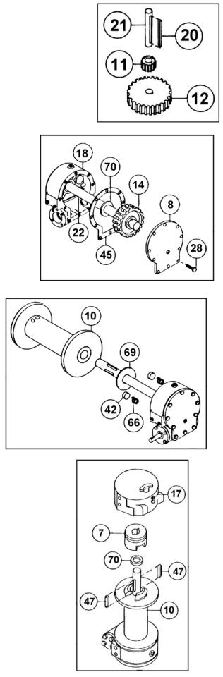
DIS-ASSEMBLY
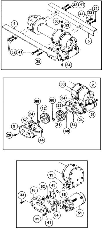
1.Drain oil from worm gear housing by removing (item #54) plug from bottom of gear housing. Remove relief fitting and reducer (items #50 & #53) from top of gear housing.
Remove mounting angles (items #4 & #5) from winch by removing hardware shown.
2.Drain oil from spur gear housing by removing (item #54) plug. Remove cover and gasket (items #9 & #44) from spur gear housing by unscrewing twelve capscrews (item #28). Slide gear (item #12) from end of worm shaft (item #23). Remove spur gear shaft (item #21), with gears attached. Check bearings (item #24) and thrust washers (item #68) for signs of wear, replace if necessary. Remove old bearings and press new bearings into place. Remove solenoid assembly (item #2) by unscrewing capscrews (items #30 & #34). Disconnect solenoid cables from motor (item #51). Make note of which terminals cables are attached to.
3.Remove key (item #19) and snap ring (item #65) from worm shaft. Remove motor (item #51) from spur gear housing (item #16) by removing (3) nuts and lock washers (items #39 & #41). Unscrew (4) capscrews (item #34) to remove spur gear box (item #16) and gasket (item #43) from gear housing. Replace lip seals (items #62 & #64) by pressing old seals from spur gear housing and pressing new seals into place.
9
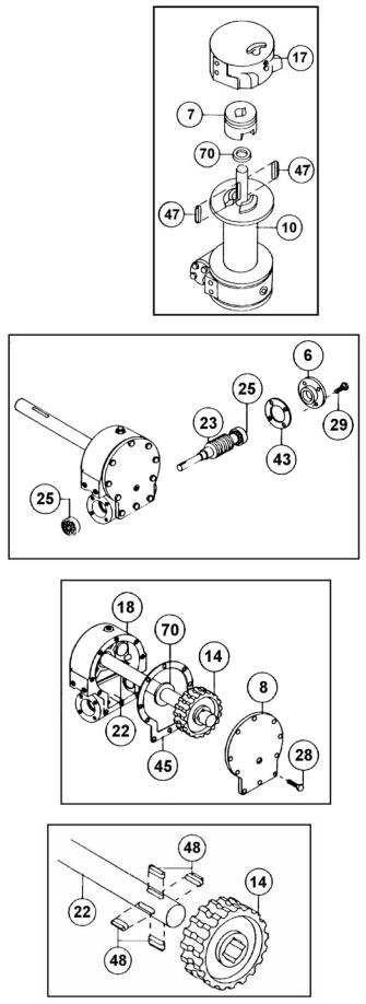
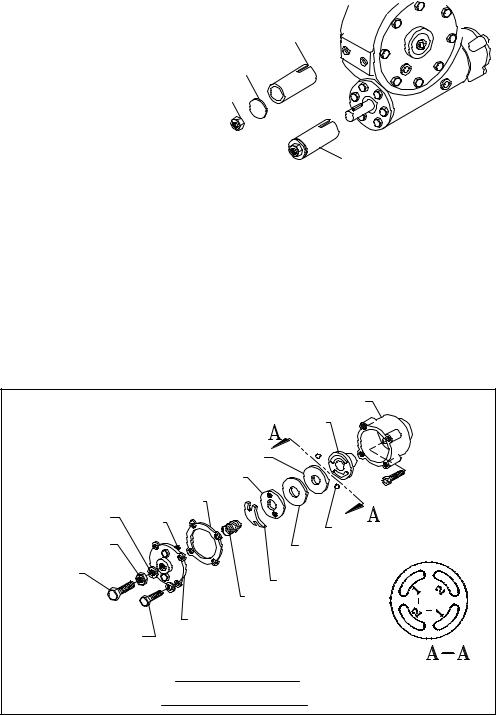
4.Slide clutch housing (item #17) from end of drum shaft. Slide jaw clutch (item #7) from end of drum shaft.
Remove (2) keys (item #47) from keyways. A screwdriver can be used, at notch, to aid in removal of keys. Once keys have been removed, drum (item #10) and thrust washer (item #70) can be removed from drum shaft. Parts under drum, thrust washer (item #69), spring and disc (item #66 & #42) should also be removed.
5.Remove bearing cap (item #6) from gear housing by unscrewing four capscrews (item #29). Remove worm (item #23) and bearing (item #25) from gear housing. Use a soft hammer to gently tap input end of worm and drive worm and bearing from gear housing. Once worm has been removed from housing, bearing can be pressed from end of worm.
Check for signs of wear to worm (item #23) and bearings (item #25). Replace if necessary.
For models with optional worm brake refer to page 6, SERVICING OF THE OIL COOLED SAFETY BRAKE, for disassembly and Page 7, for re-assembly instructions.
6.Remove gear housing cover (item #8) from gear housing (item #18) by unscrewing five remaining capscrews (item #28). Place capscrew into two tapped holes of cover and tighten. This will pull the cover loose from gear housing.
Remove cover gasket (item #45) and pull shaft (item #22), with gear attached, and thrust washer (item #70) from gear housing.
7.Check for signs of wear on gear teeth. If replacement of gear is necessary, gear must be replaced as follows:
a.Press gear (item #14) from shaft (item #22).
b.Examine shaft keys and keyways. If distortion of keys and/or keyways is evident, shaft and keys should be replaced.
c.Use a soft hammer to gently tap keys (item #48) into keyways. Press gear (item #14) over shaft and keys. Gear must be centered over keys.
10
8.Remove seal (item #63) from back of gear housing (item #18). Check bushing (item #27) for signs of wear. Press bushing (item #27) from gear housing and replace if necessary. Press new bushing and seal back into place.
9.Check drum bushings (item #26) for signs of wear. Replace if necessary by pressing old bushings from drum (item #10) and pressing new ones into place.
10.Examine shifter assembly (item #1) for damage to yoke. Yoke should be firmly attached to shaft, yet, able to swivel freely around shaft. Replace if necessary by removing pin (item #58) from handle (item #15). Remove rubber plug (item #59) from housing. Unscrew setscrew enough to allow shifter assembly to be removed from housing.
Check clutch housing bushing (item #26) fro signs of wear. Remove if necessary by pressing old bushing from housing (item #17) and pressing new one into place.
Install new shifter assembly (item #1) by placing end of shaft, opposite yoke, through spring (item #67) and into housing (item #17). Attach handle (item #15) to shaft using roll pin (item #58). Tighten setscrew, in housing, enough to allow shifter assembly to operate properly. Replace rubber plug.
11.Check cover bushing (item #8) for signs of wear. Replace if necessary by removing old bushing and pressing new bushing into place.
12.Check pinion gear on motor for signs of wear. If necessary replace gear (item #13), o-ring (item #52) and fiber washer (item #71) as follows:
a.Place fiber washer (item #71) and well oiled o-ring (item #52) over end of motor shaft and down to bottom of shaft.
b.Insert key (item #46) into motor shaft keyway. Slide pinion gear over shaft and key. Use a hammer and 7/8" (22 mm) I.D. (internal diameter) tube to drive pinion down hard enough to seat o-ring (item #52) into groove in bottom of pinion gear.
c.Slide pinion gear up toward end of shaft so that there is a 1-13/16" (46 mm) distance from top of gear to cast surface below gear. Tighten setscrew (item #36) securely enough to prevent pinion gear from moving on motor shaft.
11
13.Check gears of spur gear shaft assembly for signs of wear, replace if necessary. Press old gears from shaft (item #21). Tap key (item #20) into keyway of shaft (item #21). Press shaft through gears so that gears are centered on shaft and key.
RE-ASSEMBLY
14.Apply grease to end of shaft, opposite gear. Apply grease to bushing in gear housing (item #18). Place greased end of shaft through thrust washer (item #70) and bushing in gear housing (item #18). Place gasket (item #45) onto gear housing cover (item #8). Apply grease to gear end of shaft and bushing in cover. Place cover onto shaft and secure to housing with five capscrews (item #28) at the five lower most holes.
15.Place winch, with gear housing cover down, on work bench. Drum shaft should be in vertical position. Slide thrust washer (item #69) over drum shaft and slide downwards until washer rests on gear housing. Set springs (item #66) and drag brake disc (item #42) into pockets of gear housing. Grease bushings in drum (item #10). Slide drum assembly onto drum shaft with drum jaws upward.
16.Place thrust washer (item #70) over end of drum shaft and slide downward until spacer rests on drum. Press drum (item #10) downward to compress springs in gear housing.
Insert keys (item #47) into keyways with sharp edge of keys pointing outward and notched end of keys upward. A rubber or brass mallet will be needed to gently tap keys into position.
Apply grease to keys and end of shaft. Place jaw clutch (item #7) over end of shaft and slide jaw clutch over keys.
Set clutch housing (item #17) over end of drum shaft. Pull jaw clutch (item #7) upward, toward clutch housing, enough to allow yoke, in clutch housing, to fit properly in groove around jaw clutch.
12

17.Press bearing (item #24) onto worm (item #23). NOTE: Be sure thick shoulder of bearings outer race (side with manufacturer's name and part number) is out, away from worm threads. Press bearing and worm into gear housing. Slip gasket (item #43) onto bearing cap (item #6). Use four capscrews (item #29) to secure cap to gear housing. Torque capscrews to 7 ft-lbs. (9.4 Nm) each.
Attach solenoid assembly (item #2) to gear housing. Use two (item #34) capscrews and three (item #30) capscrews with three flatwashers (item #40). Tighten capscrews to 7 ft-lbs. (9.4Nm) each. Insert plug (item #56) into tapped hole of cover. Permatex may be applied to threads to help prevent oil leakage. TIGHTEN plug securely.
18.Press bearing (item #24) onto worm and into worm gear housing. NOTE: Be sure thick shoulder of bearings outer race (side with manufacturer's name and number) is out, away from worm threads. Place gasket (item #43) onto spur gear housing (item #16). Secure spur gear housing to worm gear housing using four capscrews (item #33). Torque capscrews to 7 ft-lbs. (9.4 Nm) each.
Mount motor (item #51) to spur gear housing (item #16) using three lockwashers and nuts (items #39 & #41). Attach solenoid cables to motor terminals. Tighten all nuts securely.
19.Place snap ring (item #65) over end of worm shaft (item #23) and set into snap ring groove. Insert key (item #19) into keyway of worm shaft. Place thrust washer (item #68) over each end of spur gear shaft (item #21). Set spur gear shaft assembly into bearing of spur gear housing. Slide gear (item #12) and (item #68) thrust washer over end of worm shaft (item #23).
Insert pins (item #57) into cover (item #9). Place gasket (item #44) onto cover. Attach cover and gasket to spur gear housing using twelve capscrews (item #28). Torque capscrews to 8 ft-lbs. (10.8 Nm.) each.
Insert plug (item #54) into bottom of spur gear housing. Permatex may be applied to threads to help prevent oil leakage.
Remove reducer and fitting (items #50 & #53) from top of spur gear housing. Pour 1/2 pint of SAE 20 weight motor oil into spur gear box. Replace reducer and fitting into top of spur gear housing. Tighten reducer and fitting securely.
20.Attach mounting angles (items #4 & #5) using six capscrews (items #32) with lockwashers and capscrews (items #35 & #31). Torque capscrews to 34 ft-lbs. (46 Nm.) each. Insert plug (item #54) into bottom of gear housing. Permatex may be applied to threads to help prevent leakage.
Pour 3/4 pint of E.P. 140 gear oil into housing thru hole in top of housing. Insert relief fitting (item #50) into reducer (item #53). Reducer should then be placed into hole on top of gear housing. Tighten fitting and reducer securely.
13
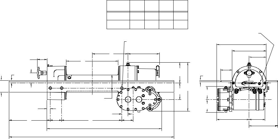
14
WINCH |
A |
B |
C |
D |
|
INCHES |
INCHES |
INCHES |
INCHES |
||
MODEL |
|||||
MM |
MM |
MM |
MM |
||
|
|||||
DC-200 |
7.78 |
11.31 |
8.94 |
13.12 |
|
|
197,6 |
287,3 |
227,0 |
333,3 |
|
DCY-200 |
5.28 |
6.31 |
11.44 |
8.12 |
|
134,1 |
160,3 |
290,5 |
206,3 |
CONNECT GROUND CABLE FROM
NEGATIVE (-) BATTERY TERMINAL HERE
|
A |
6.75 |
|
|
|
CLUTCH AT |
|
171,4 |
2.12 |
B |
|
DIS-ENGAGED |
|
|
53,9 |
|
|
POSITION |
|
|
.49 |
4.56 |
|
115,8 |
|
|
12,6 |
|
|
2.19 |
|
|
(TYP) |
55,6 |
|
|
|
|
2.50 |
|
10.25 |
63,5 |
|
|
|
260,3 |
|
(TYP) |
3.62 |
|
|
92,0 |
|
|
DRUM Ø3.50 |
|
|
88,9 |
|
|
.69 |
|
|
|
17,5 |
|
1.37 |
|
|
|
|
C |
|
D |
34,9 |
2.50 |
2.50 |
||
63,5 |
63,5 |
||
|
|
|
25.03 |
|
|
|
635,6 |
|
|
|
36.00 |
|
|
|
914,4 |
|
CONNECT POWER CABLE FROM |
|
|
POSITIVE (+) BATTERY TERMINAL HERE |
|
|
|
10.77 |
|
|
273,6 |
|
|
7.44 |
|
|
188,9 |
|
|
3.72 |
|
|
94,5 |
|
2.50 |
|
|
63,5 |
|
.25 |
(TYP) |
|
6,4 |
(TYP) |
|
2.89 |
|
|
73,5 |
|
|
2.78 |
|
|
70,7 |
|
|
|
7.05 |
3.47 |
|
179,1 |
88,2 |
|
|
6.22 |
|
|
158,0 |
DIMENSIONS SHOWN ARE INCHES OVER MILLIMETERS

15
SEE PAGE 18
FOR
SEE PAGE 17 FOR OPTIONAL WORM BRAKE PARTS LIST COMPONENT BREAKDOWN
16
PARTS LIST
Model DC-200 Series Ram-Lok®
No. |
Qty. |
Part No. |
Description |
|
No. |
Qty. |
Part No. |
Description |
1 |
1 |
276056 |
Shifter Ass'y |
|
34 |
2 |
414856 |
Capscrew 1/4 -20NC x 3/4 Lg. Socket Head zinc |
2 |
2 |
278027 |
Solenoid Assembly - 12V |
|
35 |
1 |
414912 |
Capscrew 3/8 -16NC x 5/8 Lg. Socket Head |
|
1 |
278028 |
Solenoid Assembly - 24V |
|
36 |
1 |
416029 |
Setscrew 1/4 -20NC x 5/16 Lg. Socket Head |
3 |
1 |
282001 |
Switch Assembly |
|
37 |
1 |
416030 |
Setscrew 1/4 -20NC x 3/8 Lg. Socket Head (Full Dog Point) |
4 |
1 |
302808 |
Angle (STD) |
|
38 |
1 |
416059 |
Setscrew 3/8 -16NC x 1/2 Lg. Socket Head |
|
1 |
302811 |
Angle (Mod Y) |
|
39 |
3 |
418040 |
Nut 3/8 -24NF Hex Reg zinc |
5 |
1 |
302809 |
Angle (STD) |
|
40 |
3 |
418154 |
Washer 1/4 Flat Alum. |
|
1 |
302810 |
Angle (Mod Y) |
|
41 |
10 |
418177 |
Lockwasher - 3/8 Med. Sect. Zinc |
6 |
1 |
316083 |
Cap - Bearing |
|
42 |
2 |
438014 |
Drag Brake |
7 |
1 |
324160 |
Jaw Clutch |
|
43 |
2 |
442184 |
Gasket |
8 |
1 |
328134 |
Cover - Worm Gear Housing |
|
44 |
1 |
442185 |
Gasket |
9 |
1 |
328106 |
Cover - Spur Gear Housing |
|
45 |
1 |
442205 |
Gasket |
10 |
1 |
332007 |
Drum (Mod Y) |
|
46 |
1 |
450001 |
Key |
|
1 |
332105 |
Drum (STD) |
|
47 |
2 |
450006 |
Key (Barth) |
11 |
1 |
334001 |
Idler Gear |
|
48 |
4 |
450016 |
Key (Barth) |
12 |
1 |
334003 |
Gear |
|
49 |
1 |
456001 |
Lube Fitting |
13 |
1 |
334129 |
Pinion |
|
50 |
2 |
456008 |
Relief Fitting |
14 |
1 |
334161 |
Gear R.H. - 60:1 Gear Ratio |
|
51 |
1 |
458071 |
Motor - 12V |
|
1 |
334163 |
Gear R.H. - 46:1 Gear Ratio |
|
|
1 |
458005 |
Motor - 24V |
15 |
1 |
336010 |
Handle |
|
52 |
1 |
462015 |
O-Ring |
16 |
4 |
338203 |
Housing - Spur Gear |
|
53 |
2 |
468002 |
Reducer |
17 |
1 |
338208 |
Housing - Clutch |
|
54 |
2 |
468011 |
Pipe Plug Sq. Hd. |
18 |
1 |
338273 |
Housing - Gear |
|
55 |
2 |
468017 |
Pipe Plug Soc. Hd. |
19 |
1 |
342023 |
Key - Square |
|
56 |
1 |
468018 |
Pipe Plug Soc. Hd. |
20 |
1 |
342033 |
Key - Square |
|
57 |
2 |
470001 |
Pin |
21 |
1 |
356901 |
Shaft - Spur |
|
58 |
1 |
470033 |
Spirol Pin |
22 |
1 |
357479 |
Shaft - Drum - (STD) |
|
59 |
1 |
472012 |
Plug |
|
1 |
357481 |
Shaft - Drum - (MOD. Y) |
|
60 |
1 |
472013 |
Plug |
23 |
1 |
368001 |
Worm -R.H. - 60:1 Gear Ratio |
|
61 |
1 |
482013 |
Rubber Boot |
|
1 |
368019 |
Worm -R.H. - 46:1 Gear Ratio |
|
62 |
1 |
486009 |
Oil Seal |
24 |
3 |
402001 |
Bearing - Needle |
|
63 |
1 |
486017 |
Oil Seal |
25 |
2 |
402002 |
Bearing - Ball |
|
64 |
1 |
486023 |
Oil Seal |
26 |
4 |
412003 |
Bushing |
|
65 |
1 |
490003 |
Snap Ring |
27 |
1 |
412045 |
Bushing |
|
66 |
2 |
494002 |
Spring |
28 |
22 |
414038 |
Capscrew 1/4 - 20NC x 3/4 Lg. Hex Head zinc Gr. 5 |
|
67 |
1 |
494053 |
Spring |
29 |
4 |
414045 |
Capscrew 1/4 - 20NC x 7/8 Lg. Hex Head Gr. 5 |
|
68 |
3 |
518002 |
Thrust Washer |
30 |
3 |
414059 |
Capscrew 1/4 - 20NC x 1 Lg. Hex Head zinc |
|
69 |
1 |
518014 |
Thrust Washer |
31 |
1 |
414279 |
Capscrew 3/8 -16NC x 3/4 Lg. Hex Head Gr. 5 |
|
70 |
2 |
518015 |
Thrust Washer |
32 |
6 |
414282 |
Capscrew 3/8 -16NC x 1-1/4 Lg. Hex Head zinc Gr. 5 |
|
71 |
1 |
518018 |
Fiber Washer |
33 |
4 |
414845 |
Capscrew 1/4 -20NC x 1 Lg. Socket Head NYLOK |
|
|
|
|
|
For Gasket & Seal Kit, order #246039
Item No. |
Qty. |
Part No. |
Description |
101 |
1 |
306034 |
Spring-Flat |
102 |
1 |
314008 |
Cam Plate |
1031 328128 Cover
1041 338007 Housing - Brake
1051 340002 Hub
106 |
1 |
352022 |
Retainer Plate |
107 |
2 |
400003 |
Ball |
108 |
2 |
414021 |
Capscrew 1/4 - 20NC x 1" Lg. Hex Head Gr. 5 NYLOK Heavy Patch |
109 |
4 |
414039 |
Capscrew 1/4 -20NC x 1" Lg. Hex Head Gr. 5 |
110 |
1 |
414228 |
Capscrew 3/8 -16NC x 1-1/2" Lg. Hex Head Gr. 5 All-Thread |
111 |
4 |
414821 |
Capscrew 1/4 -20NC x 7/8" Lg. Button Head Gr. 5 |
112 |
1 |
418036 |
Nut 3/8 -16NC Hex Jam |
113 |
6 |
418154 |
Washer - Flat 1/4 Alum. |
1141 442189 Gasket
1151 474001 Plate - Thrust
116 |
1 |
486069 |
Thread Seal |
117 |
1 |
494007 |
Spring |
 104
104
 105
105
|
|
115 |
|
|
106 |
|
|
114 |
116 |
108 |
111 |
|
107 |
|
|
|
|
112 |
|
102 |
110 |
101 |
|
|
|
117 |
 103
103


 109
109


 113
113


17
Solenoid Assembly Parts
278027 - 12V
278028 - 24V
 8
8 
 8
8 
 19
19 
 9
9 
 18
18 
 15
15 
 10
10 
 12
12 


 13
13 

 10
10


 14
14

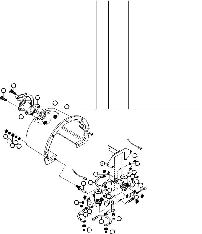
Additional Hardware comes supplied with Solenoid.
Item No. |
Qty. |
Part No. |
Description |
1 |
1 |
280009 |
Cable-Bolt Assembly |
2 |
3 |
289077 |
Wire Assembly |
3 |
1 |
289091 |
Wire Assembly |
4 |
2 |
364001 |
Strap |
5 |
2 |
364002 |
Strap |
6 |
1 |
408035 |
Solenoid Bracket |
7 |
2 |
416216 |
Screw |
8 |
2 |
416227 |
Screw |
94 418004 Nut
10 |
2 |
418022 |
Nut 3/16-18NC Hex Reg |
11 |
2 |
418140 |
Flat Washer #10 |
12 |
1 |
418163 |
Lockwasher 5/16 Med Sect Zinc |
13 |
1 |
418164 |
Shake-Proof Washer 5/16 Internal Teeth Zinc |
14 |
1 |
418165 |
Shake-Proof Washer 5/16 External Teeth Zinc |
15 |
1 |
430013 |
Female Connector |
16 |
2 |
440071 |
Terminal - Tab |
17 |
2 |
440110 |
Solenoid 12v |
|
|
440114 |
Solenoid 24v |
18 |
1 |
472071 |
Solenoid Cover |
19 |
1 |
482029 |
Cover - Connector |
20 |
4 |
530106 |
Cover Terminal |
|
Red |
|
|
|
|
Yellow |
|
|
7 |
|
|
|
|
10 |
|
|
16 |
|
|
Green |
5 |
|
|
|
17 |
|
|
|
C |
7 |
|
1 |
2 |
||
|
|||
11 |
3 |
||
|
|||
|
20 |
|
|
9 |
4 |
|
|
|
16 |
17 |
|
A |
|
|
|
|
 2
2 

 20
20 
B 


 20
20 


 20
20 
18
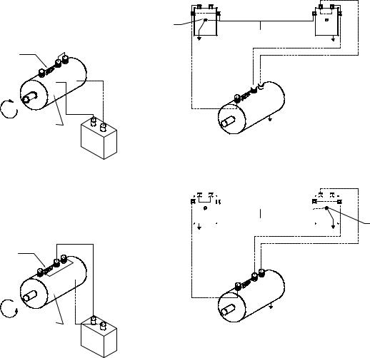
TEST PROCEDURE FOR SOLENOIDS
Steps to follow when testing current flow through DC solenoids.
It should be noted that when testing a 12 volt or 24 volt solenoid, the DC motor and battery must be of the same voltage.
To test the solenoids: (See Figure 1).
1.Securely clamp a motor to a bench or work surface.
2.Attach a #6 gauge jumper wire from "A" terminal on the motor to one of the field terminals on the motor, (F-2).
3.Attach the other motor field terminal (F-1) to one of the side terminals of the solenoid.
4.Ground the solenoid to the motor with a wire as shown.
5.Attach positive (+) battery wire to the opposite side terminal of solenoid. Ground the negative (-) battery wire to the motor housing.
6.Touch "hot" wire, from the positive battery terminal, to small terminal of the solenoid.
7.The motor should now be running if the solenoid is good. If not, make sure the motor will run directly from the battery. (See motor test procedure, Page 23).
8.To test the upper contacts use the same hookup except use the top terminals. (See Figure 2). When hooked up as shown in Figure 2, motor should start running.
When the "hot" wire is touched to the small terminal the motor will stop operating.
The top terminals are normally closed; i.e. connected, and the side terminals open, or not connected. When the solenoid operates, the top terminals are disconnected and the side terminals are connected.
Take care not to bring "hot" wires into contact with ground in order to prevent electrical arcing.
|
(TOP TERMINALS) |
|
(TOP TERMINALS) |
|||||||||||||||||||
|
|
|
|
|
|
|
|
|
|
|
|
SIDE |
|
|
|
|
|
|
|
SIDE |
||
|
|
|
|
|
|
|
|
|
|
|
|
|
|
|
|
|
|
|
||||
SIDE |
|
|
|
|
|
SIDE |
|
|
|
|
|
|
|
|||||||||
|
|
|
|
|
|
|
|
|
|
|
|
|
|
|
|
(SMALL) |
|
|
||||
|
|
|
|
(SMALL) |
|
|
|
|
|
|
|
|
|
|||||||||
|
|
|
|
|
|
|
|
|
|
|
|
|
|
|
|
|
||||||
|
|
|
|
|
|
|
|
|
|
|
|
|
|
|
|
|
|
|
|
|
|
|
|
|
|
|
|
|
|
|
|
|
|
|
|
|
|
|
|
|
|
|
|
|
|
|
|
|
|
|
|
|
|
|
|
|
|
|
|
|
|
|
|
|
|
|
|
|
SOLENOID |
|
(MOTOR |
|
SOLENOID |
|
(MOTOR |
|
|
|
|
|
|
|||
|
|
HOUSING) |
|
|
|
HOUSING) |
|
GROUND WIRE |
|
|
|
GROUND WIRE |
|
|
|
|
|
|
FROM SOLENOID |
|
|
|
|
FROM SOLENOID |
|
|
|
|
|
|
|
|
|
|
TO MOTOR |
|
|
|
|
TO MOTOR |
|
|
|
|
|
|
|
|
|
|
|
|
|
|
|
|
F2 |
F1 |
A |
|
|
F1 |
A |
|
|
|
|
F2 |
|||
|
|
|
|
|
|
|
|
(+) |
|
MOTOR |
|
|
|
|
|
(-) |
|
(+) |
|
|
|
|
|
BATTERY |
FIGURE 1 |
|
|
|
(-) |
|
|
|
|
|
|
BATTERY
FIGURE 2
Field (C)
Armature
Field (B)
SOLENOID
ASSEMBLY
TO BATTERY
Field (A) |
* See Solenoid Assembly |
page 21 for connection of A, B, & C cable to solenoids.
TO ARMATURE
A* C* B*
19
TEST PROCEDURE FOR MOTOR
The Ramsey Winch motor is a (4 pole-4 coil) series wound 12 volt or 24 volt DC motor.
The 4 pole-4 coil feature provides high torque at low speeds.
To test the motor to determine if it is functioning properly, first securely fasten the motor to a bench or work surface so it will not jump or move around during test procedure (the starting torque of motor is high).
1.Connect a jumper wire (at least a number 6 wire) from F- 1 to "A" motor terminals (See Figure 1)
2.Attach a wire (at least a number 6 wire) from positive
(+) battery terminal to F-2 motor terminal. Ground negative (-) battery terminal to motor housing (See Figure 1). Motor should now run.
To reverse the direction of rotation:
1.Attach jumper wire from F-2 to "A" motor terminals (See Figure 2).
2.Attach wire from positive (+) battery terminal to F-1 motor terminal. Ground negative (-) battery terminal to motor housing (See Figure 2).
NOTE: Always attach battery wire solidly to motor terminals. Make and break the connection of the negative (-) battery terminal at the motor housing. This avoids burning the motor terminals.
CAUTION: DO NOT RUN THE MOTOR FOR A LONG PERIOD OF TIME IN FASHION MENTIONED ABOVE, BECAUSE THE MOTOR COULD BECOME DAM-
AGED.
The motor running idle on the bench will draw 55 amperes and must run free and easy. If the ampere draw is more than 60 amperes and the motor runs rough or has a strange sound, it should be replaced.
With the motor attached in place on a winch (less cable on drum) the ampere draw should be approximately 65 to 70 amperes.
If after following the procedure outlined, the test on the winch significantly exceeds 70 amperes, refer to your Owner's Manual for trouble shooting suggestions on the mechanical portion of the winch.
See Figure 3 for the solenoids connection to the motor and the battery.
(PULL COILS |
|
INSIDE MOTOR) |
A |
|
F1 |
|
F2 |
GROUND
CW
(MOTOR HOUSING)
BATTERY
FIGURE 1
MOTOR-CLOCKWISE ROTATION
(PULL COILS |
|
INSIDE MOTOR) |
A |
F1 |
|
F2 |
|
CCW |
GROUND |
(MOTOR HOUSING) |
|
BATTERY
SMALL TERMINAL |
|
|
|
TO BATTERY'S |
|
SOLENOID |
POSITIVE TERMINAL |
SOLENOID |
A
F1 

F2
MOTOR
GROUND
THE DASHED LINES ARE CURRENT'S PATH IN FORWARD ROTATION.
SOLID LINES ARE CURRENT'S PATH AT ALL TIMES.
NOTE: DIRECTION OF MOTOR ROTATION DEPENDS ON WHICH SMALL
TERMINAL OF EITHER SOLENOID IS CONNECTED TO BATTERY'S
POSITIVE TERMINAL.
|
|
|
|
|
|
|
|
|
|
|
|
|
|
|
|
|
|
|
|
|
|
|
|
|
|
|
|
|
|
|
|
|
|
|
|
|
|
|
|
|
|
|
|
TO BATTERY'S |
|
|
|
|
|
|
|
|
SMALL TERMINAL |
|
|
|
|
|
|
|
|
POSITIVE TERMINAL |
|
|
|
|
|
|
|
|
|
|
|
|
SOLENOID |
SOLENOID |
|||||||||||||
|
|
|
|
||||||||||||||
A
F1
F2
MOTOR
GROUND
THE DASHED LINES ARE CURRENT'S PATH IN REVERSE ROTATION.
SOLID LINES ARE CURRENT'S PATH AT ALL TIMES.
FIGURE 2 |
FIGURE 3 |
MOTOR-COUNTER-CLOCKWISE ROTATION |
SOLENOIDS TO MOTOR CONNECTIONS |
|
20 |
MANUEL D’UTILISATION,
DE DÉPANNAGE
ET D’ENTRETIEN
MODÈLE DE LA GAMME DC-200
TREUILS INDUSTRIELS
BAS ÉQUIPÉS RAM-LOK®
COMPREND : DC-200/DC-246, DC-24-200/DC-24-246. DCY-200/DCY- 246, DCY-24-200/DCY-24-246 ET MODÈLES ÉQUIPÉS DE FREIN DE SÉCURITÉ RÉGLABLE, AUTOMATIQUE EN OPTION REFROIDI PAR HUILE : TREUILS DES GAMMES DCG-200 ET DCYG-200
MISE EN GARDE : ASSUREZ-VOUS DE LIRE ET DE COMPRENDRE CE MANUEL AVANT D’INSTALLER ET D’UTILISER LE TREUIL. N’OUBLIEZ PAS LES AVERTISSEMENTS ET MISES EN GARDE.

TABLE DES MATIÈRES
INTRODUCTION . . . . . . . . . . . . . . . . . . . . . . . . . . . . . . . . . . . . . . . . . . . . . . . . . . . . . . . . . . . . . . . . . . . . . . . .23 INFORMATIONS DE GARANTIE . . . . . . . . . . . . . . . . . . . . . . . . . . . . . . . . . . . . . . . . . . . . . . . . . . . . . . . . . . . . .23 CARACTÉRISTIQUES TECHNIQUES . . . . . . . . . . . . . . . . . . . . . . . . . . . . . . . . . . . . . . . . . . . . . . . . . . . . . . . . .23 AVERTISSEMENTS . . . . . . . . . . . . . . . . . . . . . . . . . . . . . . . . . . . . . . . . . . . . . . . . . . . . . . . . . . . . . . . . . . . . .23 TECHNIQUES D’UTILISATION . . . . . . . . . . . . . . . . . . . . . . . . . . . . . . . . . . . . . . . . . . . . . . . . . . . . . . . . . . . . . .24 INSTALLATION DU CÂBLE . . . . . . . . . . . . . . . . . . . . . . . . . . . . . . . . . . . . . . . . . . . . . . . . . . . . . . . . . . . . . . . .24 ENTRETIEN DU TREUIL . . . . . . . . . . . . . . . . . . . . . . . . . . . . . . . . . . . . . . . . . . . . . . . . . . . . . . . . . . . . . . . . . .25 FIXATION DU TREUIL . . . . . . . . . . . . . . . . . . . . . . . . . . . . . . . . . . . . . . . . . . . . . . . . . . . . . . . . . . . . . . . . . . . .25 BRANCHEMENTS ÉLECTRIQUES . . . . . . . . . . . . . . . . . . . . . . . . . . . . . . . . . . . . . . . . . . . . . . . . . . . . . . . . . . .25 RÉGLAGE DU FREIN DE SÉCURITÉ REFROIDI PAR HUILE . . . . . . . . . . . . . . . . . . . . . . . . . . . . . . . . . . . . . . . .26 ENTRETIEN DU FREIN DE SÉCURITÉ REFROIDI PAR HUILE . . . . . . . . . . . . . . . . . . . . . . . . . . . . . . . . . . . . . . .26 REMONTAGE ET VÉRIFICATION DU FREIN . . . . . . . . . . . . . . . . . . . . . . . . . . . . . . . . . . . . . . . . . . . . . . . . . . . .27 TEST DE MONTAGE CORRECT DU FREIN . . . . . . . . . . . . . . . . . . . . . . . . . . . . . . . . . . . . . . . . . . . . . . . . . . . .27
INSTRUCTIONS DE VÉRIFICATION DU MONTAGE ET
MISE EN PLACE DU FREIN À VIS SANS FIN . . . . . . . . . . . . . . . . . . . . . . . . . . . . . . . . . . . . . . . . . . . . . . .27 GUIDE DE RÉSOLUTION DES PROBLÈMES . . . . . . . . . . . . . . . . . . . . . . . . . . . . . . . . . . . . . . . . . . . . . . . . . . .28
INSTRUCTIONS DE RÉVISION DES TREUILS RAMSEY RAM-LOK® DES GAMMES DC-200
DÉPOSE . . . . . . . . . . . . . . . . . . . . . . . . . . . . . . . . . . . . . . . . . . . . . . . . . . . . . . . . . . . . . . . . . . . . . . . . . . .29-32 REMONTAGE . . . . . . . . . . . . . . . . . . . . . . . . . . . . . . . . . . . . . . . . . . . . . . . . . . . . . . . . . . . . . . . . . . . . . . .32-33 PLAN COTÉ . . . . . . . . . . . . . . . . . . . . . . . . . . . . . . . . . . . . . . . . . . . . . . . . . . . . . . . . . . . . . . . . . . . . . . . . . . .34 LISTE ET SCHÉMA DES PIÈCES . . . . . . . . . . . . . . . . . . . . . . . . . . . . . . . . . . . . . . . . . . . . . . . . . . . . . . . . .35-37 LISTES DES PIÈCES DU SOLÉNOÏDE . . . . . . . . . . . . . . . . . . . . . . . . . . . . . . . . . . . . . . . . . . . . . . . . . . . . . . . .38 TEST DU SOLÉNOÏDE . . . . . . . . . . . . . . . . . . . . . . . . . . . . . . . . . . . . . . . . . . . . . . . . . . . . . . . . . . . . . . . . . . .39 TEST DU MOTEUR . . . . . . . . . . . . . . . . . . . . . . . . . . . . . . . . . . . . . . . . . . . . . . . . . . . . . . . . . . . . . . . . . . . . . .40
GARANTIE LIMITÉE
RAMSEY WINCH garantit chaque treuil RAMSEY neuf contre tout défaut de matériau et de fabrication pendant une période d’un (1) an à partir de la date d’achat. L'obligation aux termes de cette garantie, statutaire ou autre, est limitée au remplacement ou à la réparation à l’u- sine du fabricant, ou à un endroit désigné par le fabricant, de la pièce qui semblera présenter un défaut de fabrication ou de matériau, suite à l'inspection effectuée par le fabricant.
Cette garantie n’oblige pas RAMSEY WINCH à s’acquitter des frais de main-d'ouvre ou de transport liés au remplacement ou à la réparation des pièces défectueuses, et ne s'applique pas à un produit ayant subi des réparations ou des modifications (sauf si elles ont été autorisées par le fabricant), ou en cas de mauvaise utilisation de l’équipement, de négligence ou de matériel mal installé.
RAMSEY WINCH ne pourra en aucun cas être tenue responsable des dommages particuliers et indirects. RAMSEY WINCH n’émet aucune garantie au sujet des accessoires et portant par exemple sur les garanties de leurs fabricants respectifs. RAMSEY WINCH s’efforce de poursuivre une politique d’amélioration constante et se réserve par conséquent le droit d'améliorer ses produits par le biais de modifications de leur conception ou des matériaux employés, selon les besoins, et sans être obligée d'incorporer ces modifications aux produits fabriqués précédemment.
En cas d’intervention sur le terrain à la demande de l’acquéreur, et si la défaillance s’avère ne pas provenir du produit RAMSEY WINCH, l’acquéreur s’engage à s’acquitter auprès du représentant des frais correspondant au temps et aux dépenses.
Les factures d'entretien, de main-d’ouvre et autres frais engagés par l’acquéreur sans l'accord ou l'autorisation de RAMSEY WINCH ne seront pas acceptées.
Reportez-vous à la carte de garantie pour les détails.

GAMME DE TREUILS ÉLECTRIQUES RAMSEY DC-200
VEUILLEZ LIRE SOIGNEUSEMENT CE MANUEL.
Ce manuel contient des conseils utiles pour l'utilisation efficace de votre treuil Ramsey ; il aborde aussi les procédures de sécurité à connaître absolument avant l’utilisation d’un tel équipement.
INFORMATIONS DE GARANTIE
Les treuils Ramsey sont conçus et fabriqués selon des spécifications rigoureuses. Ils font tous l’objet d’un travail soigné et compétent. En cas de besoin, la procédure de recours en garantie est détaillée au verso de votre carte de garantie préadressée à port payé. Veuillez lire et remplir la carte de garantie ci-jointe, et l'envoyer à Ramsey Winch Company. En cas de problème avec votre treuil, suivez les instructions fournies afin d’obtenir un service rapide de recours en garantie.
*CARACTÉRISTIQUES TECHNIQUES : conformes à la norme SAE J706**
câble, première |
lbs. |
…………………………………………………………………… |
8,000 |
|||
Kg. |
…………………………………………………………………… |
3,620 |
||||
couche |
||||||
|
|
|
|
|
||
Démultiplication |
DC-200 …………………………………………………………………… |
470 |
||||
DC-246 |
…………………………………………………………………… |
360 |
||||
|
||||||
|
|
|
||||
Poids à l’expédition : |
DC-200/DC-246 (long drum).……………………………………………. |
116 lbs (52.7 Kg) |
||||
DCY-200/DCY-246 (short drum).…………………………………………. |
105 lbs (47.6 Kg.) |
|||||
|
||||||
|
|
|||||
|
|
|||||
LA TEMPÉRATURE MAXIMALE DE L’HUILE DE LA BOÎTE D’ENGRENAGES NE DOIT PAS DÉPASSER : |
250° F (121° C) |
|||||
|
|
|
|
|
|
|
|
|
|
|
|
|
|
Couche de câble |
|
1 |
2 |
3 |
4 |
|
|
|
|
|
|
|
|
*Traction nominale |
lbs. |
8,000 |
6,700 |
5,700 |
5,000 |
|
par couche de câble |
Kg. |
3,620 |
3,030 |
2,580 |
2,260 |
|
|
|
|
|
|
|
|
*Capacité du câble |
ft. |
25 |
60 |
95 |
140 |
|
(Standard) |
m |
7 |
18 |
28 |
42 |
|
|
|
|
|
|
|
|
*Capacité du câble |
ft. |
15 |
30 |
55 |
75 |
|
(Y Drum) |
m |
4 |
9 |
16 |
22 |
|
|
|
|
|
|
|
|
*Vitesse du câble |
FPM |
15 |
30 |
55 |
75 |
|
MPM |
4 |
9 |
16 |
22 |
||
|
||||||
|
|
|
|
|
|
|
* Ces spécifications sont basées sur un câble de 9.5 mm de diamètre en acier de charrue amélioré 6x19
** Le treuil est uniquement conforme à la norme SAE J706. Pour les qualifications SAE des angles de montage, le cas échéant, consultez Ramsey Engineering.
REMARQUE : les tractions nominales indiquées sont uniquement pour le treuil. Consultez le fabricant du câble pour les caractéristiques nominales de ce dernier.
 AVERTISSEMENTS
L’EMBRAYAGE DOIT ÊTRE ENTIÈREMENT ENCLENCHÉ AVANT DE COMMENCER TOUT TREUILLAGE. NE RELÂCHEZ JAMAIS L’EMBRAYAGE EN PRÉSENCE D’UNE CHARGE.
NE LAISSEZ PAS L’EMBRAYAGE ENCLENCHÉ LORSQUE LE TREUIL N’EST PAS UTILISÉ.
NE VOUS PLACEZ JAMAIS SOUS UNE CHARGE SOULEVÉE NI À PROXIMITÉ.
RESTEZ À L’ÉCART DU CÂBLE LORS DU TREUILLAGE. N’ESSAYEZ PAS DE GUIDER LE CÂBLE.
NE DÉPASSEZ PAS LES CARACTÉRISTIQUES DE TRACTION NOMINALES MAXIMALES INDIQUÉES DANS LE TABLEAU. N’UTILISEZ PAS LE TREUIL POUR SOULEVER, MAINTENIR OU TRANSPORTER DES PERSONNES.
IL CONVIENT DE CONSERVER AU MINIMUM CINQ TOURS DE CÂBLE AUTOUR DU TAMBOUR POUR MAINTENIR LA CHARGE. L’ATTACHE DU CÂBLE N’EST PAS CONÇUE POUR ASSURER LE MAINTIEN D’UNE CHARGE.
DÉBRANCHEZ LE COMMUTATEUR DE COMMANDE À DISTANCE DU TREUIL LORSQU’IL N’EST PAS UTILISÉ.
23
TECHNIQUES D’UTILISATION
Pour vous familiariser avec votre treuil, il est vivement conseillé de l’essayer avant de vraiment l’utiliser. Préparez votre essai à l’avance. N’oubliez pas que vous entendez votre treuil autant que vous le voyez fonctionner. Apprenez à reconnaître le son d'une traction légère et régulière, celui d'une lourde charge ou encore celui provoqué par des à-coups ou une déviation de la charge. Prenez l’habitude de faire fonctionner votre treuil et tout deviendra automatique.
L’enroulement irrégulier du câble lors de la traction d’une charge ne présente pas de problème sauf en cas d’accumulation du câble sur un côté du tambour. Dans ce cas, inversez le fonctionnement du treuil afin de soulager la charge et déplacez votre point d’attache vers le centre du véhicule. Une fois le travail terminé, vous pouvez dérouler le câble et l’enrouler à nouveau d’une manière régulière.
S’il existe le moindre risque de rupture du câble lors de la traction d’une charge, placez une couverture, une veste ou une bâche sur le câble à environ 1,8 m du crochet. Ceci devrait ralentir le retour du câble en cas de rupture et réduire les risques de blessures graves.
Contrôlez le niveau d’huile du treuil tous les six mois. Remplacez l’huile tous les ans ou plus souvent en cas d’utilisation fréquente. Utilisez 0,35 l d’huile E.P. 140 polyvalente dans la boîte de la vis sans fin et 0,23 l de SAE 20 dans la boîte d’engrenages. Si l’huile est souillée par des particules métalliques, examinez le treuil afin de déceler tout signe d’usure anormale.
Vérifiez régulièrement tous les branchements électriques et tous les boulons de fixation. Serrez les pièces si besoin est.
La caractéristique minimale d’ampère-heure de la batterie du véhicule doit être de 70 et celle-ci doit être utilisée avec un alternateur d’au moins 40 ampères. Il est conseillé de disposer d’une batterie de secours pour fournir une alimentation supplémentaire.
Inspectez fréquemment le câble. Tout câble effiloché ou comportant des brins brisés doit être remplacé immédiatement. Il est possible de se procurer un câble et un crochet auprès d’un distributeur Ramsey.
L’embrayage semi-automatique RAM-LOK® permet un déroulement rapide du câble à partir du tambour afin de le fixer à une charge. L’embrayage s'actionne comme indiqué ci-dessous au moyen de la poignée en forme de T qui se trouve à l'extrémité du treuil.
1.POUR RELÂCHER L’EMBRAYAGE, faites fonctionner le treuil en marche arrière (déroulement) jusqu’à ce que la charge ne porte plus sur le câble. Tirez la poignée d'embrayage vers l’extérieur, faites-la tourner de 90º dans le sens inverse des aiguilles d’une montre, puis relâchez-la. L’embrayage est alors supprimé et le câble peut être tiré à la main.
2.POUR ENCLENCHER L’EMBRAYAGE, tirez la poignée vers l’extérieur, faites-la tourner de 90º dans le sens des aiguilles d’une montre et relâchez-la. Faites tourner le treuil en marche arrière jusqu’à ce que sa poignée se réenclenche complètement ou jusqu’à ce que le tambour commence à tourner. À ce point, assurez-vous que la poignée est complètement rentrée. Il est possible de retirer le bouchon en plastique du haut du carter afin de vérifier si l'embrayage est bien enclenché. Une fois l’embrayage entièrement réenclenché, le treuil est prêt à enrouler le câble.
INSTALLATION DU CÂBLE
1.Déroulez le câble sur le sol pour éviter qu'il ne se torde. Recouvrez bien l’extrémité du câble opposée au crochet d’un ruban adhésif plastique ou de type équivalent pour éviter qu’elle ne s’effiloche.
2.Insérez l’extrémité du câble opposée au crochet dans le trou de 1,2 cm de diamètre du tambour. Fixez le câble sur le tambour au moyen de la vis de pression fournie avec le treuil. SERREZ FERMEMENT LA VIS.
3.Faites tourner avec précaution le treuil dans le sens de l’enroulement. Conservez une tension sur l’extrémité du câble et enroulez tout le câble sur le tambour en veillant à former des couches régulières.
24
ENTRETIEN DU TREUIL
L’observation du calendrier de maintenance suivant vous permettra de maintenir votre treuil en bon état et garantira un fonctionnement avec un minimum de réparations.
A. |
HEBDOMADAIRE |
1. |
Vérifiez le niveau d’huile et maintenez-le au niveau du bouchon. En cas de fuite d’huile, déterminez l’emplacement de la |
|
fuite et réparez. |
2. |
Vérifiez le bouchon d’échappement en haut de la boîte d’engrenages. Assurez-vous qu’il fonctionne bien afin que les gaz |
|
issus de l’huile chaude puissent être évacués. |
3. |
Lubrifiez le câble avec de l’huile légère. |
B. |
MENSUEL |
1.Lubrifiez les divers graisseurs situés dans le tambour du câble, le roulement d’extrémité, le carter d’embrayage ou la tringlerie d'embrayage. Vous pouvez utiliser toute graisse de bonne qualité contenant du bisulfure de molybdène.
2.Vérifiez l’action du crabot baladeur et assurez-vous qu’il s’enclenche sur le tambour du câble et s'en dégage complètement. Retirez le bouchon en plastique du haut du carter et vérifiez si l’embrayage s’enclenche bien. S'il ne s'enclenche pas à fond, examinez les pièces de l'embrayeur afin de déceler toute trace de détérioration ou d’usure excessive, et procédez aux remplacements éventuellement nécessaires. Observez les mâchoires de l’embrayage et du tambour afin de déceler tout arrondissement des surfaces. Si elles se sont arrondies, changez immédiatement les pièces.
3.Vérifiez les boulons de fixation du treuil. Remplacez tout boulon manquant et serrez fermement les autres. Veillez à utiliser uniquement des boulons de grade 5 ou supérieure.
4.Vérifiez le couple de serrage du frein à vis sans fin refroidi à l’huile. Procédez à tout réglage nécessaire, conformément à la procédure décrite dans la section RÉGLAGE DU FREIN À VIS SANS FIN REFROIDI PAR HUILE du manuel de l’utilisateur.
5.Vérifiez l’alignement de la chaîne et des pignons, et procédez aux réglages nécessaires pour réduire l’usure.
6.Examinez le câble. Tout câble dénudé ou effiloché doit être remplacé immédiatement.
C.ANNUEL
1.Le treuil doit être vidangé une fois par an ou plus souvent en cas d’usage fréquent.
2.Remplissez le treuil de kérosène propre jusqu’au niveau du bouchon de niveau d’huile. Faites fonctionner le treuil quelques minutes sans charge, dans le sens de l’enroulement. Éliminez le kérosène du treuil.
3.Remplissez le treuil d’huile pour engrenages E.P. 140 polyvalente jusqu’au bouchon de niveau d’huile.
4.Examinez le châssis et la structure afin de déceler toutes déformations ou fissures éventuelles.
5.Pour évaluer l’usure des engrenages, secouez le tambour et, si nécessaire, vidangez l'huile et retirez le couvercle pour un examen plus approfondi.
FIXATION DU TREUIL
Ce treuil doit absolument être monté correctement afin que les trois principales parties soient alignées (l’extrémité du carter d’embrayage, le tambour du câble et l’extrémité de la boîte d'engrenages).
Tous les treuils standard des gammes DC-200 sont livrés avec les cornières de montage recommandées. Leur taille est de 6 x 63 x 63 x 9100 mm, et ils sont fabriqués en acier à haute résistance.
BRANCHEMENTS ÉLECTRIQUES
Consultez le schéma coté de la page 45. Utilisez un câble d’alimentation avec des bornes appropriées, reliez la borne positive
(+) de la batterie sur le goujon de 8 mm de diamètre du capot du solénoïde en plastique du treuil. IMPORTANT : maintenez l’écrou intérieur sur le goujon avec une clé tout en serrant l’écrou extérieur. Utilisez un câble mis à la terre avec des bornes appropriées, reliez la borne négative (-) de la batterie au boulon de fixation du treuil de 9 mm de diamètre le plus près de la bride du tambour, du côté moteur du treuil. Pour les distances inférieures ou égales à 4,5 m entre la batterie et le treuil, utilisez du fil de calibre 2 pour les branchements ci-dessus. Pour les distances supérieures à 4,5 m, utilisez un calibre supérieur à 2.
25
 Loading...