

Page 1
49-830.fm Page 1 Thursday, August 19, 1999 10:37 AM
Cat. No.
49-830
OWNER’S MANUAL
RS-3000 Auto Security Alarm System
Please read this entire manual
before
you begin installation.
Page 2

g
g
g
g
g Sy
y
g
y
49-830.fm Page 2 Thursday, August 19, 1999 10:37 AM
FEATURES
Your RS-3000 Auto Security Alarm
System’s voice alert warns away potentia l thi eves a nd al erts y ou to trouble in a clear, loud, male voice and
shouts out a panic alert in a female
voice. It also includes advance d features that help protect your vehicle
from theft, yet you can install it in less
than an hour. The two convenient
key-chain transmitters lets you arm
and disarm the system, sound a panic alert, or activate the car finder feature when you are away from your
vehicle.
Your RS-3000 includes these features.
The following features ma rked
Note:
with an asterisk (*) might qualify you
for a discount on your vehicle insurance premium. Show your insuran ce
agent the supplied certificate.
Talkin
Alarm with 120 dB Alert
—
advises you of the alarm’s status
(armed or disarmed) and warns away
potential thieves.
Piercin
, 120 dB Siren
— loud
enough to be heard from hundreds of
feet away.
Passive Armin
— automatically
arms the system after you exit the vehicle.
Starter Kill
— prevents anyone from
starting your vehicle when the system
is armed.
RadioShack is a trademark used by Tandy C orporation.
2
1997 Tandy Corporation.
All Rights Reserved.
Need Help? Call 1-800-598-2527
Electronic Dual-Sta
— sounds a pre-alert warning the
sor
e Shock Sen-
first time someone strikes your vehicle, then sounds the alert if it is hit
again within 30 seconds.
Current Sens in
stem
— triggers
the alert when a door or trunk is
opened and the vehicle’s dome or
trunk light turns on, or when your vehicle is hot wired, by sensing the current draw.
Current Sens or B
pass
— lets yo u
turn off current sensing if other electronic devices in your vehicle (such
as a high-power audio system or cellular phone) make your alarm sound
false alerts.
Status Indicator
— mounted in plain
view, lets you easily determine the
status of the alarm system (armed or
disarmed) and warns away potential
thieve s.
Hi
h Theft Alert Mode
— lets you
set the alarm to announce that it is
armed or to chirp every 30 seconds.
Two Eas
motes
-to-Use Key-Chain Re-
— let you easily control your
alarm from a distance.
Car Finder
— lets you make the
alarm sound beeps to help you find
your vehicle in a crowded parking lot.
Page 3

49-830.fm Page 3 Thursday, August 19, 1999 10:37 AM
Instant Panic Alarm
— calls out in a
female voice to alert others nearby
that you need assistance when you
are in or near your vehicle.
Valet Mode
— lets you easily prevent
passive arming when the vehicle is
being serviced, valet parked, or
washed.
Programmable Options
— lets you
customize several of your alarm’s options.
Accessory Trigger Output
— provides a negative trigger to activate
(but not power) accessory sensors.
Violation Confirmation
— beeps
three times or says “I was tampered
with!” when you disarm the system after the alarm has sou nded, to let you
know what happened wh ile you were
away from the vehicle.
Computer-Controlled Fan Sensor
— can tell the difference between
your vehicle’s dome or tr unk lig ht and
an electric cooling fan (which can
make other alarms sound a false
alert) without using additional wiring.
Warning:
Your alarm syst em’s alerts
are painfully loud. Take care during
installation to keep your head away
from the system once you connect
power.
FCC INFORMATION
Your alarm syst em mi g ht ca u se TV or
radio interference even when it is operating properly. To determine whether your system is causing the
interference, move your vehicle out of
the area. If the interference goes
away, your alarm system was causing the interference. T ry to eliminate
the interference by:
• Keeping your system away from
the receiver
• Contacting your local RadioShack store for help
If you cannot eliminate the interference, the FCC requires that you stop
using your alarm system.
Toll-Free Help
— if you have any
questions about or problems with
your alarm system, just call:
1-800-598-2527
Your system requires one 9-volt alkaline battery to maintain operation if
the main power lead is disconnected.
Need Help? Call 1-800-598-2527
3
Page 4

g
g
49-830.fm Page 4 Thursday, August 19, 1999 10:37 AM
CONTENTS
Installing the System ..................................................................................... 5
Supplied Ite ms ........ ................. ................ ................. ......... ................. ....... 5
Installation Order ........... ................. ................ ................. ................ .......... 6
Connecting the Starter Disable Module ..................................................... 6
Connecting the System to Power ...................................... ....... ....... .......... 7
Activating the Remote Controls ................................................................. 8
Installing the Backup Battery ..................................................................... 8
Mounting the System ................................................................................. 9
Installing the Status Indicator .................................................................. 10
the Alarm System ............................................................................... 11
Usin
Arming the Alarm ...................................................................................... 11
Temporarily Reducing the Shock Sensor’s Sensitivity ....................... 11
High Theft Alert .................................................................................. 11
Sounding the Panic Alarm ........................................................................ 11
Alarm Violations ....................................................................................... 12
Disarming the System ............................................................................. 12
Using the Car Finder ............................................................................... 12
Setting the System’s Options .................................................................. 13
Setting the Shock Sensor’s Sensitivity .............................................. 13
Setting the Current Sensor ............................................................... 13
Setting the Valet Mode (Passive Arming/Disarmin g) ........................ 14
Troubleshootin
Care and Maintenance ................................................................................. 17
Replacing the Fuse .................................................................................. 18
Replacing a Remote Control’s Battery .................................................... 18
Specifications ............................................................................................... 19
4
........................................................................................... 15
Need Help? Call 1-800-598-2527
Page 5
49-830.fm Page 5 Thursday, August 19, 1999 10:37 AM
INSTALLING THE SYSTEM
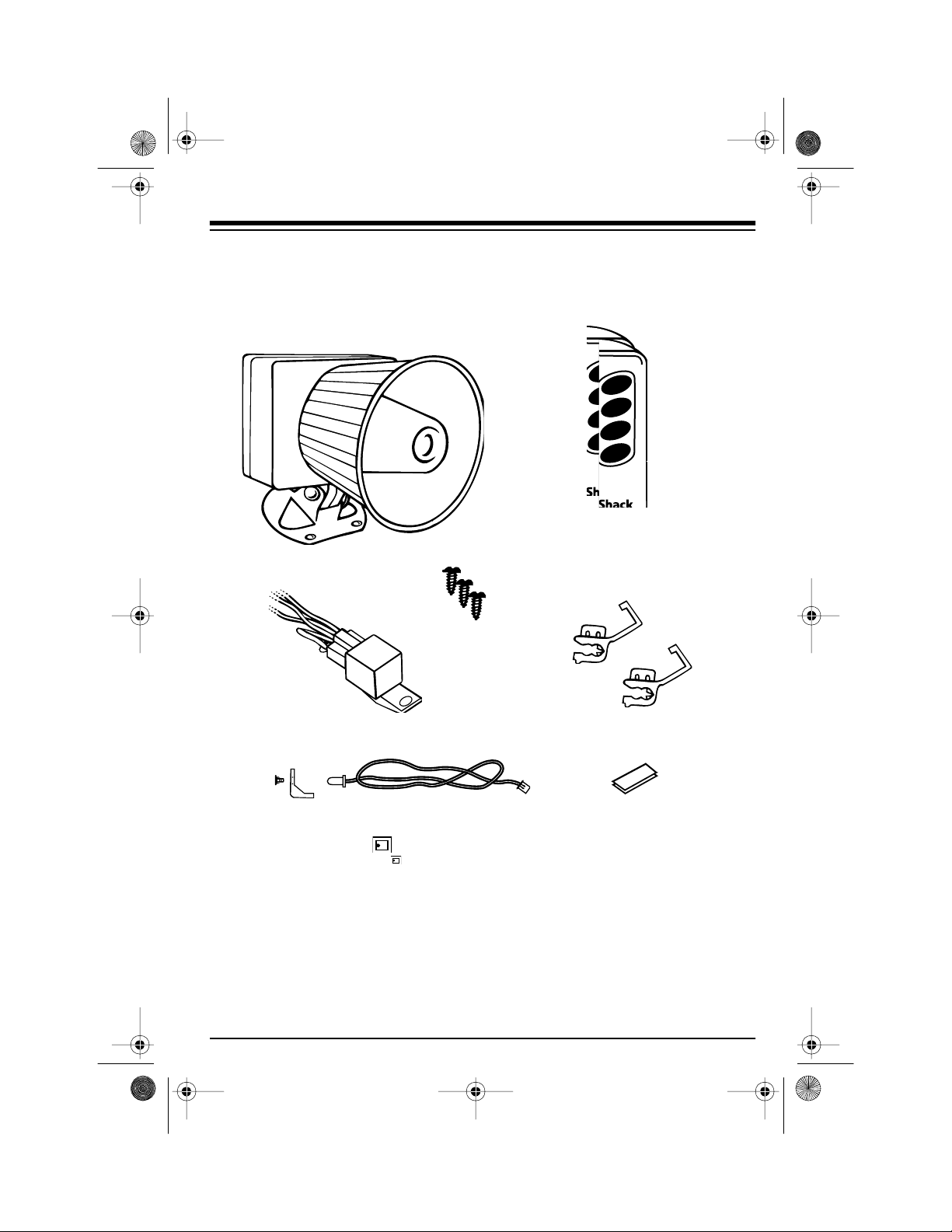
SUPPLIED ITEMS
Your alarm system includes the following items:
Main System
Two Four-Button Remotes
Mounting Screws
Status Indicator with Bracket and Harness
Wire Ties
Need Help? Call 1-800-598-2527
Wire Tap-In ConnectorsStarter Disable Relay
Double-Sided Tape
5
Page 6

49-830.fm Page 6 Thursday, August 19, 1999 10:37 AM
INSTALLATION ORDER
You can install your system in just 6
easy steps:
1. Connect the starter disable mo dule.
2. Connect the system to power.
3. Train the remote controls.
4. Install the backup battery.
5. Mount the system.
6. Install the status indicator.
We recommend you get a wiring diagram for your veh icle before you begin, so you can easily find your
vehicle’s starter solenoid wire. Wiring
diagrams are available from your vehicle’s dealer or from the Auto Security Helpline at 1-800-598-2527.
You also need a 12-volt test lamp or
DC voltmeter and a wire-piercing
probe adapter (such as RadioShack
Cat. No. 278-715) to ensure proper
installation.
CONNECTING THE
STARTER DISABLE
MODULE
The starter disable module interrupts
power to your vehicle’s starter solenoid so the vehicle does not start
when the system is armed. Follow
these steps to connect the module.
1. Using the starter solenoid’s colorcoded wires as a guide, locate
the wire that goes from your vehicle’s ignition (key) switch to the
solenoid. This wire is most easily
found where the wires connect to
the ignition switch near the stee ring column.
2. Connect the negative (usually
black) lead from a 12-volt test
lamp or DC voltmeter to a metal
vehicle body part.
3. Connect the wire-piercing probe
to the positive lead and press the
pin tip through the solenoid wire’s
insulation and into the wire itself.
4. Start your vehicle. The test light
should light or the meter should
indicate voltage
engine is cranking
is stopped or running).
only while the
(not while it
If the test fails, repeat Steps 2–4
using a different wire until you
find the correct one.
6
Need Help? Call 1-800-598-2527
Page 7
49-830.fm Page 7 Thursday, August 19, 1999 10:37 AM
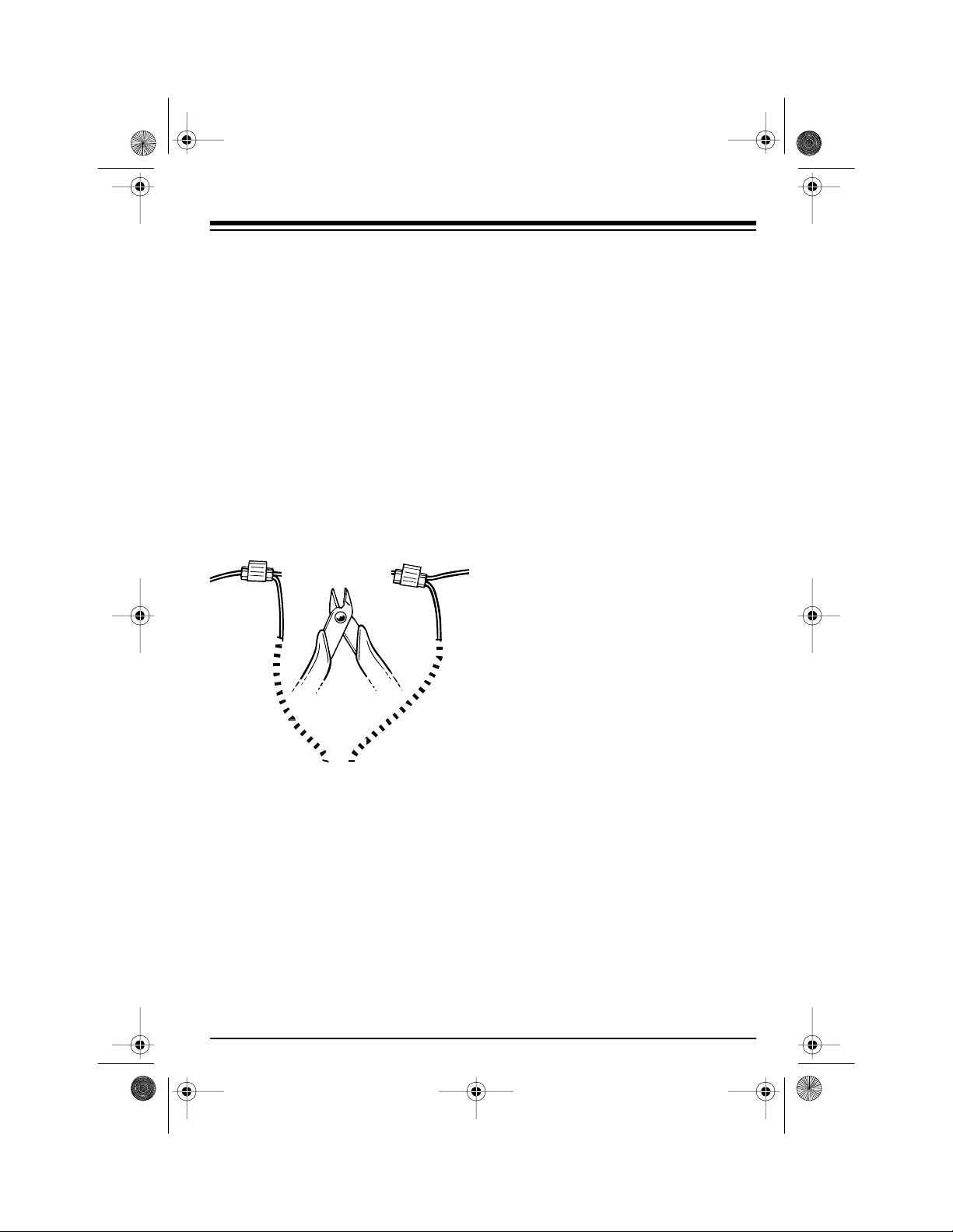
5. Turn off the engine. Then cut t he
wire you located in Steps 2–4 at a
point where there are several
inches of wire on each side of the
cut.
After you c ut th is wi r e, yo u
Note:
are unable to start your vehicle
until you complete the installation.
6. Use one of the supplied yellow
wire tap-ins to connect the sta rter
disable module’s white wire to the
wire going to the solenoid.
To Starter
Solenoid
White
Wire
To Ignition
Switch
Red
Wire
8. Route the main system ’s orange
wire through an existing hole in
the firewall, or drill a
1
/4-inch hole
in the firewall, taking care not to
damage anything on the other
side of the firewall. Then plug the
starter disable module’s orange
wire into the main system’s
orange wire.
If you drill a hole, use a
Note:
rubber grommet to protect the
wire from abrasion.
9. Use a wire tie to secure the
starter disable module under the
dashboard.
CONNECTING THE
SYSTEM TO POWER
Warning:
muffle the alarm’s speaker before you
connect the system to power. The
alarm is extremely loud.
We recommend that you
To the Starter Disable Module
7. Use the other yellow wire tap-in
to connect the starter disable
module’s red wire to the wire
going to the ignition switch.
Need Help? Call 1-800-598-2527
Follow these steps to connect the
system to power.
1. Connect the system’s red lead to
your vehicle battery’s positive (+)
terminal.
2. Connect the system’s black lead
to a metal part of the vehicle’s
body that is not insulated from the
main chassis by a plastic part, or
to the battery’s negative (–) terminal. The system says “Thank
you!”
7
Page 8

49-830.fm Page 8 Thursday, August 19, 1999 10:37 AM
ACTIVATING THE
REMOTE CONTROLS
You must train the sy stem t o respond
to the supplied remote controls.To activate both remote controls, immediately after applying power, press
TALK
on one of the remotes. The sys-
tem says “System Armed.” Press
ARM TALK
tem. The system says “System Disarmed.”
If the system loses power and the
backup battery is dead or not installed, the system stops responding
to both remotes. Simply follow this
procedure again to reactivate them.
Both of the supplied system remotes
share the same remote code, but
your system can learn two remote
codes if you want to add another remote control (Cat. No. 49-845). To
activate a second remote control
code, be sure the system is disarmed, then hold down
10 seconds. The system says “Thank
You.” Press any button on the new remote to activate it.
again to disarm the sys-
ARM TALK
ARM
for
INSTALLING THE
BACKUP BATTERY
A 9-volt battery (not supplied) powers
your alarm if its main power is cut.
Follow these steps to install the battery.
Note:
For the best protection and
longest life, we recomm end you use
an alkaline battery, such as RadioShack Cat. No. 23-553.
1. Slide off the compartment cover.
2. Snap a 9-volt battery onto the
battery contacts.
3. Place the battery in the compartment.
4. Replace the compartment cover.
A new battery powers the alarm for
about 21 hours with no alert, or 15
minutes of continuous alert. The
alarm’s volume is redu ced when it is
operating from the battery.
We recommend you replace the battery every 6 months, even if it has not
been used to power the system.
8
Need Help? Call 1-800-598-2527
Page 9

49-830.fm Page 9 Thursday, August 19, 1999 10:37 AM
MOUNTING THE
SYSTEM
Select a location for your alarm system in the engine compartment. For
the best results, the location should
meet the following conditions.
• All wires should reach the ir connections without going near moving or hot engine parts.
Note:
If necessary, you can
extend the wires using hook-up
wire and butt connectors. Use at
least 18-gauge wire and an insulated wire connector to extend a
wire.
• The mounting location shou ld be
solid and have no mechanisms or
moving parts on its other side.
• For the best remote range, the
mounting location should allow
the system’s yellow antenna wire
to hang straight down. Do not cut
or extend the wire — its length is
optimized for best operation.
• For the loudest siren, the siren
horn should point down toward
the pavement.
Once you select a location, follow
these steps to mount the system.
1. Hold the system against the
selected location and mark the
locations of the three mounting
holes.
2. Drill
1
/8-inch holes at the marked
locations, taking care not to drill
into anything behind the mounting surface.
3. Secure the system to the surface
using the supplied screws.
Note:
For the best shock-sensor
operation use all three screws.
• The alarm should not point
straight up, as moisture could collect in the siren horn and damage
the system.
• To prevent water damage, the
system should not be mounted in
a wheel well, directly behind the
radiator grill, or close to the
ground.
Need Help? Call 1-800-598-2527
9
Page 10

49-830 .fm Page 10 Thursday, Augu st 19, 1999 10:37 AM
INSTALLING THE
STATUS INDICATOR
The status indicator goes inside your
vehicle’s passenger compartment. Either drill a mounting hole in a dash
panel or use the supplied mounting
bracket to hold the indicator. Follow
these ste ps to i nstall th e indicator.
1. Locate an existing wire harness
that goes through your vehicle’s
firewall, and push the indicator
into the passenger compartment
through the existing hole.
If you cannot find an existing wi re
harness, drill a
through the firewall into the passenger compartment. Then push
the indicator through the hole.
Cautions:
• Before drilling, be sure you can
reach the other side of the
hole.
• Do not drill into any mecha-
nism on the other side of the
firewall.
• Protect the wire by placing a
rubber grommet (not supplied)
in the hole, and route the wire
through the grommet.
1
/4-inch hole
bottom of the brack et. Then peel
off the adhesive backing from the
other side of the tape and press
the bracket onto the dash.
If you are mounting the ind icator in the dash,
drill a
5
/16-inch
hole at the desired location.
3. Press the supplied grommet into
the mounting hole from the front
of the surface.
Grommet Indicator
4. Press the indicator into the grommet from the back of the surface.
5. Plug the indicator’s harness into
the matching harness o n t he system.
6. Use the supplied wire tie to
secure the wire out of the way.
7. If you drilled a hole in the firewall,
use silicon sealan t (not supp lied)
to waterproof the hole.
If you are using the supplied
2.
mounting bracket,
use denatured alcohol to clean the mount ing surface and let the surface
dry completely. Peel the backing
off of one side of the doublesided tape and press it onto the
10
Need Help? Call 1-800-598-2527
Page 11

y
49-830 .fm Page 11 Thursday, Augu st 19, 1999 10:37 AM
USING THE ALARM SYSTEM
ARMING THE ALARM
To arm the alarm in the voice
press
mode,
says “System Armed.”
To arm the s
mode,
chirps once.
Notes:
press
• The status indicator flashes when
the system is armed.
• The system ignores current-
sensing violations for 40 seconds after it arms.
• The system ignores shock-sen-
sor violations for 8 seconds after
it arms.
• If the valet mode is turned off, the
system arms 60 seconds after
you turn off your vehicle.
ARM TALK
stem in the chirp
ARM CHIRP
Temporarily Reducing the
Shock Sensor’s Sensitivity
If you are parking in a severe weather
situation, near a construction zone, or
near heavy traffic, you can temporarily reduce the system’s shock sensor
sensitivity to help prevent false
alarms. To reduce the sensitivity to
half its normal level, first press
or
TA L K
tem in the desired mode. Then, within
2 seconds, press the other
ton (if you first pressed
ARM CHIRP
. The alarm
. The alarm
ARM
to arm the sys-
but-
ARM
ARM TALK
press
ARM CHIRP
ty). The alarm says “Thank you.”
To completely turn off the shock sen-
sor, press the other
within 2 seconds of arming. The
alarm says “Thank you” each time
you press the button.
When you disarm and rearm the system, the shock sensor returns to its
previou s se ns it iv it y s et ting.
to reduce sensitivi-
button twice
ARM
High Theft Alert
If you park your vehicle in a highcrime area, you can further protect
your vehicle by having the alarm announce that it is protected every 30
seconds.
To turn on this feature, press
within 2 seconds of arming. If you
armed the system in the voice mode,
the system says “System Armed” every 30 seconds. If you armed the system in the chirp mode, the system
chirps twice every 30 seconds.
SOUNDING THE PANIC
ALARM
To sound a panic alarm, press and
release
“Please help me!” and sounds loud
tones for 30 seconds. P ress any button to stop the panic alarm sooner.
,
. The alarm screams
PA NI C
FINDER
Need Help? Call 1-800-598-2527
11
Page 12

49-830 .fm Page 12 Thursday, Augu st 19, 1999 10:37 AM
ALARM VIOLATIONS
Your alarm senses violations by monitoring your vehicle’s electrical system
(current sensing) and by detecting impacts (shock sensing).
An alert sounds immediately if the
current sensor detects an electrical
drain such as occurs when a dome or
trunk light turns on.
The first time the alarm senses an impact that exceeds its sensitivity level,
it says “You are too close to the vehicle. Please, move aw ay” (if armed in
the voice mode) or chirps 3 times (if
armed in the chirp mode). If it senses
another impact within 30 seconds, the
system sounds a full alert.
Note:
If an impact is severe, a single
impact can cause a full alert to sound,
without giving a warning.
When your alarm senses a v iolation,
it sounds an alert for 30 seconds. If
you armed the system in the voice
mode, it yells “I was tampered with”
and sounds loud tones. If you armed
the system i n the chirp m ode, the system sounds loud tones. To silence
the alert sooner, press any button.
DISARMING THE
SYSTEM
To disarm the system, press either
ARM TALK
tem confirms that it is disarmed by
saying “System disarmed” or by
beeping twice.
Notes:
• The status indicator is off when
the system is disarmed.
• If the valet mode is turned off, the
system rearms itself after 1
minute if you have not started the
vehicle.
• If the system detected a violation
while you were away, it says “I
was tampered with” or beeps
three times when you disarm it.
ARM CHIRP
or
. The sys-
USING THE CAR FINDER
The car finder helps you f ind your vehicle in a dark or crowded parking lot.
To use the car finder, with the system
armed, press
chirps 8 times.
FINDER
. The alarm
12
Need Help? Call 1-800-598-2527
Page 13

49-830 .fm Page 13 Thursday, Augu st 19, 1999 10:37 AM
SETTING THE SYS TEM’S
OPTI ONS
You can adjust the following options:
• Shock Sensor Sensitivity
• Current Sensor (On/Off)
• Val et Mode (On/Off)
Setting the Shock Sensor’s
Sensitivity
The shock sensor’s initial setting is
fine for most situations. To test the
shock sensor, strike your vehicle on
the hood directly over the alarm.
If the shock sensor is too sensitive or
not sensitive enough, follow these
steps to set it to a different level.
1. With the alarm disarmed, hold
FINDER
down
“Please adjust sensor now.”
2. Within 2 seconds, strike your
vehicle with as much force as you
want the alarm to respond to. The
alarm responds with “Thank you.”
Any shock equal to or greater
than the setting triggers the alert.
Notes:
• If you do not strike your vehicle
within 2 seconds, the alarm is set
to its highest sensitivity. This
could cause frequent false alerts.
until the alarm says
Setting the Current Sensor
If your vehicle has electronic accessories that turn on and off automatically while you are away from the
vehicle, the alarm might sound false
alerts. (The system can detect an
electric engine fan, and does not
sound a false alert when the fan
comes on.)
To disable the current sensor so accessories do not trigger an alert, disarm the system. Then hold down
PANIC
for about 2 seconds. The sys-
tem chirps twice.
To re-enable the current sensor, with
the system disarmed, hold down
IC
for about 2 seconds. The system
chirps once.
Notes:
• The current sensor does not
operate for 40 seconds aft er the
system arms.
• You can also try unplugging or
disconnecting electronic accessories such as radar detectors or
cellular phones when you leave
your vehicle, instead of disabling
the current sensor, to prevent the
false alerts.
P AN-
• The shock sensor does not operate for 8 seconds after you arm
the system.
Need Help? Call 1-800-598-2527
13
Page 14

49-830 .fm Page 14 Thursday, Augu st 19, 1999 10:37 AM
Setting the Valet Mode
(Passive Arming /Disar ming)
The valet mode lets you leave your
vehicle for service or with a valet and
have it arm 60 seconds after you
not
turn off the engine. The def ault is for
the valet mode to be on (passive arming is off).
To have your system automatically
arm 60 seconds after you turn off the
engine, hold down
ARM CHIRP
about 10 seconds. T he system says
“System Armed.”
To turn on the valet mode (so the system does not passively arm), hold
down
ARM CHIRP
again for about 10
seconds. The system says “System
Disarmed.”
for
14
Need Help? Call 1-800-598-2527
Page 15

49-830 .fm Page 15 Thursday, Augu st 19, 1999 10:37 AM
TROUBLESHOOTING
This section describes some problems y ou might encounter and gives possibl e
solutions.
Problem Possible Solution
Frequent false alerts
• Another accessory is triggering the alarm. Try
turning off current sensing to see if this solves the
problem. If it does, try turning it back on, then
removing other accessories, one by one, until
you find which accessory is triggering the false
alert. If possible, turn off that accessory when you
leave your vehicle. Common problem accessories are cellular phones, radar detectors, and
vehicle self-test systems. If you cannot turn off
the accessory, leave current sensing disabled.
Your alarm can tell the difference between
Note:
the vehicle’s electric fan and other accessories,
so the fan does not trigger a false alert if the fan
turns on while the system is armed.
The alarm is not loud
enough
• Your alarm’s electrical connections are not making good contact. Check the connections and, if
necessary, connect the powe r and ground leads
to the vehicle’s battery terminals.
• The shock sen sor is too sensitive. S ee “Setting
the Shock Sensor’s Sensitivity” on Page 13 to
change the sensor’s setting.
• Loud thunderclaps and heavy machinery can
trigger a false alarm. If you know a thunderstorm
is approaching or that heavy machinery will be
used nearby you can temporarily reduce the
shock sensor’s sensitivity or turn it off entirely.
See “Temporarily Reducing the Shock Sensor’s
Sensitivity” on Page 11.
• The system is operating from its backup battery.
Check all power connections.
• The siren is being muffled by the engine or hood.
Try repositioning the siren so it points to the
pavement.
Need Help? Call 1-800-598-2527
15
Page 16

49-830 .fm Page 16 Thursday, Augu st 19, 1999 10:37 AM
Problem Possible Solution
Alarm does not operate • Check all power connections.
• Check the system’s fuse. If it has blown, see
“Replacing the Fuse” on Page 18.
• Check the remote control’s battery. See “Replacing a Remote Control’s Battery” on Page 18.
Alarm does not sound
when it should
• The shock sensor is not sensitive enough. See
“Setting the Shock Sensor’s Sensitivity” on
Page 13. If you set the shock sensor to its maximum sensitivity and the alarm still does not
sound, confirm that yo u mounted the alarm o n a
solid, metal vehicle part (not on the frame or on
rubber or plastic parts). If necessary, reposition
the alarm for better performance.
• If you have a large vehicle, the shock sensor
might not detect impacts on parts of the vehicle
far from the system. Remember that most thieves
break into your vehicle through o ne of the front
doors or windows. If you set the system sensitive
enough to detect all impacts, you might experience frequent and annoying false alarms.
The remote control’s
range is poor
16
• Confirm that you have not accidently disabled
current sensing. See “Setting the Current Sensor” on Page 13.
• The antenna wi re is too close to metal. I f possible, position the yellow antenna wire away from
metal.
• The antenna wi re has been cut or ext ended. T he
antenna wire is factory tuned for the best performance (a longer antenna ac tually does not work
as well as the short included antenna wire). If the
wire has been cut, take the system to your local
RadioShack store for repair service.
Need Help? Call 1-800-598-2527
Page 17

49-830 .fm Page 17 Thursday, Augu st 19, 1999 10:37 AM
CARE AND MAINTENANCE
Your RadioShack RS-3000 Auto Security Alarm System is an exam ple of superior design and craftsmanship. The following suggestions will help you care for
the alarm so you can enjoy its protection for years.
Keep the remote controls dry. If they get wet, wipe them dry immediately. Liquids can contain m inerals that might corrode the
electronic circuits.
Handle the alarm and remotes gently and carefully. Dropping
them can damage circuit boards and cases and m ight make the
remotes work improperly.
Use and store the remote controls only in normal temperature environments. Temperature extrem es can shorten the life of electronic devices, damage batteries, and distort or melt plastic parts.
Keep the remote controls away from dust and dirt, which can
cause premature wear of parts.
Do not use harsh chemicals, cleaning solvents, or strong deter-
CLEANER
gents to clean the alarm.
Use only fresh batteries of the recommended size and type in
your alarm and remote controls. Old or weak batteries can leak
chemicals that can damage your system’s internal circuits.
Modifying or tampering with your alarm’s internal components can cause a malfunction and might invalidate the alarm’s warranty and void your FCC authorization to operate it. If your alarm is not operating as it should, take it to your local
RadioShack store for assistance.
Need Help? Call 1-800-598-2527
17
Page 18
49-830 .fm Page 18 Thursday, Augu st 19, 1999 10:37 AM
REPLACING THE FUSE
Follow these steps to check the system’s fuse and replace it if it has
blown. The system us es a 5-amp 1
1
/4-inch fast-acting fuse (Cat. No.
×
270-1011).
1. Push together the two halves of
the inline fuse holder (on the red
power wire) and twist them to
separate the halves.
2. Inspec t the fuse. If the wire is broken or not there, replace it.
Caution:
Use only a fuse o f the
same type and rating. Using a different type of fuse or bypassing
the fuse protection can damage
your alarm or your vehicl e’s electrical system.
3. Put the new fuse in the holder
and push and twist the holder’s
halves together.
1
REPLACING A REMOTE
CONTROL’S BATTERY
If your remote control’s range is re-
/
4
duced or if the indicator does not light
when you press a button, repla ce its
battery. Each remote control uses a
12-volt remote control battery (Cat.
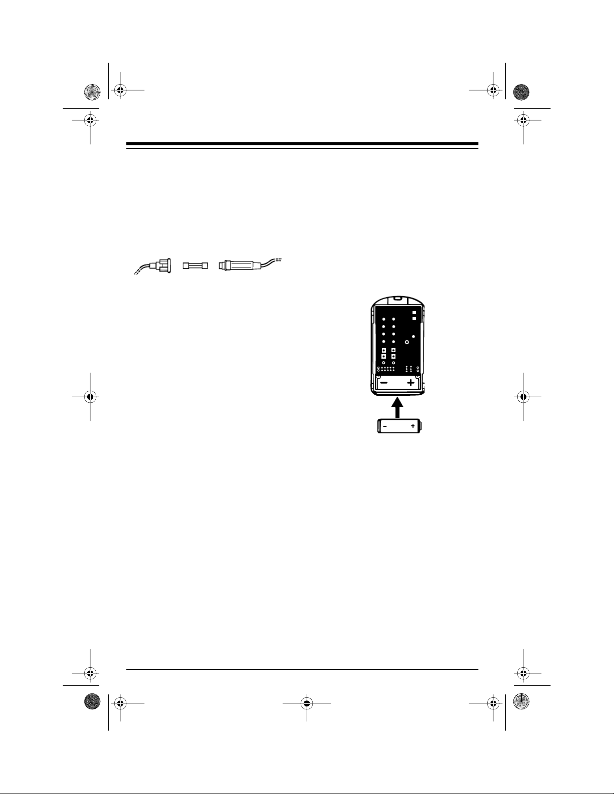
No. 23-144). Follow these steps to replace the battery.
1. Snap apart the remote control’s
case.
Caution:
any of the remote control’s
pieces.
Take care not to lose
18
2. Replace the battery with a new
one.
3. Put all parts back in place and
snap the case halves back
together.
Need Help? Call 1-800-598-2527
Page 19

49-830 .fm Page 19 Thursday, Augu st 19, 1999 10:37 AM
SPECIFICATIONS
Siren Sound Level ................................................ More than 120 dB at 1 Meter
Current Drain ........................... .......... ......... .......... ......... .......... 22 mA (Standby)
1 Amp (Siren Sounding)
Power Requirements ................................................................... 9–16 Volts DC
Alarm Weight ....................................................................................... 1 lb, 8 oz
Remote Carrier Frequency .......................................................... . 303.875 MHz
RF Output Power ................................................................ 5,580 µV at 1 Meter
Remote Control Power ................................................. 12-Volt Alkaline Battery
Remote Weight ......................................................................................... 1.5 oz
Specifications are typical; individual un its might vary. Specifications are subject
to change and improvement without notice.
Need Help? Call 1-800-598-2527
19
Page 20

49-830 .fm Page 20 Thursday, Augu st 19, 1999 10:37 AM
Limited Ninety- Day Warranty
This product is warr anted by RadioSh ack agains t manufacturi ng defects in mat erial and workm anship under nor mal use for ninety (90) days from the date of p urchase from RadioShack companyowned stores and au thorized R adioSh ack fr anch isees and dealer s. In the even t of a pro duct defec t
during the warranty period, take the product and the RadioShack sales receipt as proof of purchase
date to any RadioShack store. Radi oShack will, at its option, unless otherwise provided by law:
(a) correct the defec t by product repair without charge for parts and labor; (b) replace the produc t
with one of the same or similar design; or (c) refund the purchase price. All replaced parts and products, and products on which a refund is made, become the property of RadioShack. New or reconditioned parts and products may be used in the performance of warranty service. Repaired or replaced
parts and products are warranted for the remainder of the original warranty period. You will be
charged for repair or replacement of the product made after the expiration of the warranty period.
This warranty does not cover: (a) damage or failure caused by or attributable to acts of God, abuse,
accident, misuse, imp roper or abnormal us age, failure to foll ow instr uctions , impro per install ation or
maintenance, altera tion, lightning or other incidence of excess volta ge or current; (b) any repairs
other than those prov ided by a RadioShac k Authorized Service Faci lity; (c) consumables such as
fuses or batteries; (d) cosme tic damag e; (e ) transpor tation, s hip ping or insurance costs ; or (f) costs
of product removal, installation, set-up service adjustment or reinstallation.
EXCEPT AS PROVIDED HEREIN, RadioShack MAKES NO EXPRESS WARRANTIES AND ANY
IMPLIED WARRANTIES, INCLUDING THOSE OF MERCHANTABILITY AND FITNESS FOR A
PARTICULAR PURPOSE, ARE LIMITED IN DURATION TO THE DURATION OF THE WRITTEN
LIMITED WARRANTIES CONTAINED HEREIN. EXCEPT AS PROVIDED HEREIN, RadioShack
SHALL HAVE NO LIABILITY OR RESPONSIBILITY TO CUSTOMER OR ANY OTHER PERSON
OR ENTITY WITH RESPECT TO ANY LIABILITY, LOSS OR DAMAGE CAUSED DIRECTLY OR
INDIRECTLY BY USE OR PERFORMANCE OF THE PRODUCT OR A RISING OUT OF ANY
BREACH OF THIS WARRANTY, INCLUDING, BUT NOT LIMITED TO, ANY DAMAGES RESULTING FROM INCONVENIENCE, LO SS OF TIME, DATA, PROPERTY, REVENUE, OR PROFIT OR
ANY INDIRECT, SPECIAL, INCIDENTAL, OR CONSEQUENTIAL DAMAGES, EVEN IF RadioShack HAS BEEN ADVISED OF THE POSSIBILITY OF SUCH DAMAGES.
Some states do not allow the limitations on how long an implied warranty lasts or the exclusion of incidental or consequential damages, so the above limitations o r exclusions may not a pply to you .
This warranty gives y ou specific legal rights, and y ou may also have other rights which vary from
state to state.
RadioShack Customer Relations, Dept. W, 100 Throckmorton St., Suite 600, Fort Worth, TX 76102
We Service What We Sell
1/97
RadioShack
A Division of Tandy Corporation
Fort Worth, Texas 76102
2/97 Printed in the USA
 Loading...