

Rademacher 35000462 User guide
Installation and
EN
operating instructions
DuoFern Universal Dimmactuator ush-mounted (fm)
Item no. 3500 04 62
VBD 562-2 (04.13)
1. General safety instructions
The use of defective equipment can lead to personal
injury and damage to property.
Never use defective or damaged equipment. Please contact
our Customer Service department in the event of faults
Mortal danger in the event of connecting unsuitable
devices.
Overloading the Universal Dimmactuator (fm) by connecting
unsuitable devices can lead to overheating, short circuits and
re under certain circumstances.
◆ For this reaso n, only conn ect lamps to th e D uoFern
Universal Dimmactuator (fm) as specied in the “Correct
usage” chapter.
2. Correct usage
Only use the DuoFern Universal Dimmactuator (fm) for connection and control
of the following electric lamps:
◆ Conventional bulbs
◆ Lamp transformers with:
- Leading-edge phase control or
- Trailing-edge phase control
2. Correct usage
Operating conditions
◆ O nly use the DuoFern Universal Dimmactuator (fm) in dry rooms.
◆ For the ele ctrical connection a 230 V/50 Hz power supply, together
with a site-provided isolating device (fuse), must be available at the
installation site.
◆ The installation and operation of the DuoFern radio system and its com-
ponents (e. g. DuoFern Universal Dimmactuator (fm)) is only permitted
for those systems and devices where a malfunction in the transmitter
or receiver would not cause a danger to persons or property or where
this risk is already covered by other safety equipment.
3. Incorrect use
Never use the DuoFern radio system and its components for remote control
of devices and systems with heightened safety-relevant requirements or
a heightened ri sk of accident. Such use would require add itional safe ty
equipment. Observe the respective statutory regulations for the installation
of such systems.
IMPOR TANT
Do not install the DuoFern Universal Dimmactuator (fm) outdoors.
The following types of lamp may not be used as they cannot be
dimmed:
◆ Fluorescent lamps
◆ Low-energy bulbs
◆ LED lamps
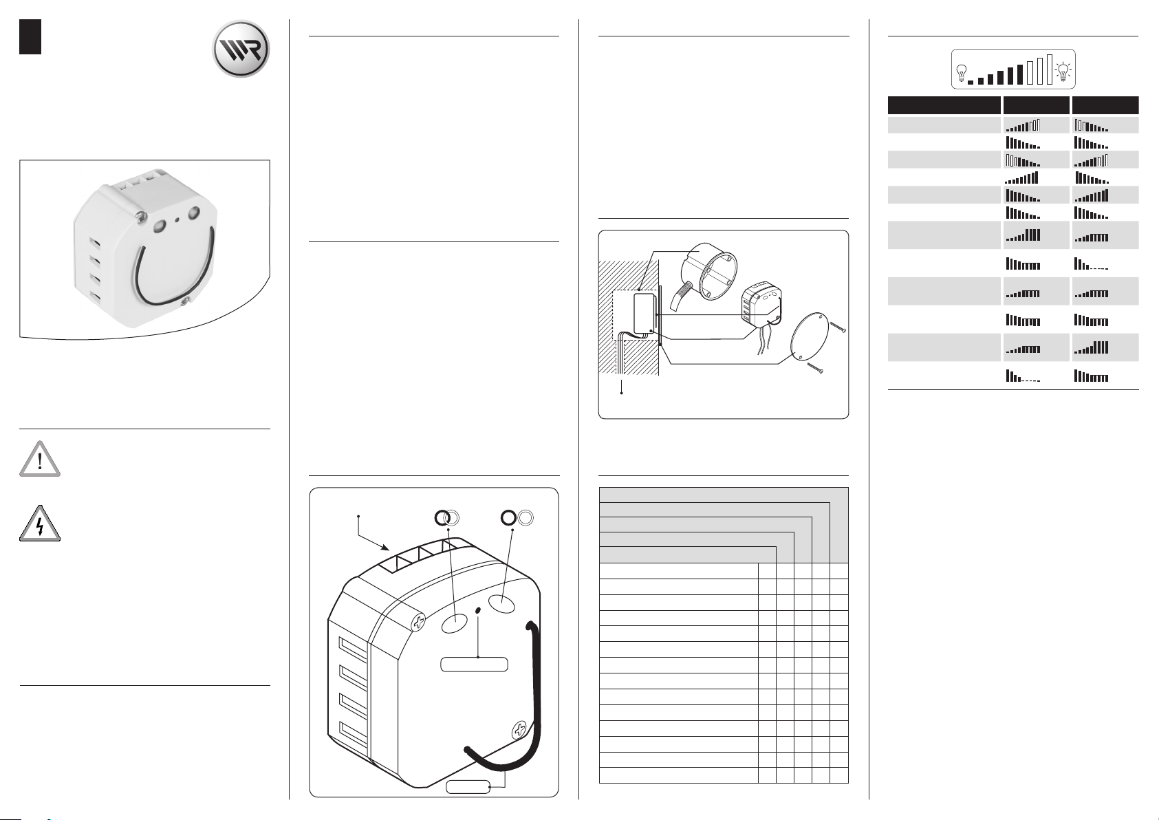
4. General view
Connection terminals Disconnect button
Connect button
Indicator light
Antenna
4.1 Functional description
The D uoFern Universal Dimmactuator (fm) can be used to integrate and
control electric lamps within a DuoFern network. In order to use the functions
of the corresponding DuoFern controllers (e. g. DuoFern manual transmitter
standard), you must connect the DuoFern Universal Dimmactuator (fm) to
the DuoFern network.
The two buttons can be used to switch the Universal Dimmactuator (fm)
between connect and disconnect mode. A bi-coloured indicator light shows
whether the DuoFern actuators connected to the Universal Dimmactuator
(fm) have received and conrmed the control commands.
4.2 The installation principle
Flush-mounted box
Antenna
DuoFern Universal
Dimmactuator (fm)
Cover plate
Connecting cables
4.3 Functional characteristics
DuoFern environmental sensor Item no. 3200 00 64
DuoFern manual central operating unit Item no. 3481 00 60
RolloTron Pro Comfort DuoFern Item no. 1523 45 11
DuoFern Standard manual transmitter Item no. 3248 03 66
DuoFern Wall controler Item no. 3216 02 11
Manual control (on/o )
Random functi on
Manual operation (on/o)
Timer (on/o )
Automatic solar func tion (on/o)
Solar program
Automatic dawn functi on (on/o)
Automatic dawn functi on
Automatic dusk func tion (on/o)
Automatic dusk func tion
Mode change
Connection test
Radio code
Runtime
● ● ● ●
● ●
● ●
● ●
● ●
● ●
● ●
● ●
● ●
● ● ●
● ● ●
● ●
●
●
4.4 Overview of switching commands and actions
0 % 100%
Switching commands Mode 1 Mode 2
UP # 100 % 0 %
STOP 0 % 0 %
#
DOWN
Automatic dawn functi on 100 %
Automatic dusk function 0 % 100 %
Solar program 0 % 0 %
Up with current dimming
direction 100%
Up with current dimming
direction 0%
STOP with current dimming
direction 100%
STOP with current dimming
direction 0%
Down with current dimming
direction 100%
Down with current dimming
direction 0%
#
If the last intermediate state has been reached, then the Universal Dimm actuator (fm) stops here. No intermediate state is stored upon connecting
the mains.
*
The current brightness of the lamp is stored as the intermediate state.
NOTE
◆ Automatic commands are dimmed to the target value as quickly as
possible.
◆ The dimming time for manual commands can be congured via the
running time feature.
◆ Use mode 2 when operating the DuoFern Universal Dimmactuator (fm)
in combination with roller shutters.
Manual control behaviour for use with a local switch.
Brief press = switches ON/OFF, no stop when reaching the inter-
mediate state
Press and hold = dims alternately (on to 100% and o to 0%), the new
dimmed value will be stored as the intermediate
value.
Random function
The actuator can process random function switching commands. If a switching command is received which is to be delayed by the random function, then
processing of the switching command is delayed by up to 30 minutes. The
LED ashes green once per second during the delay period.
0 % 100 %
100% STOP
*
STOP
*
STOP
*
STOP
*
STOP
0% STOP
0 %
0%
STOP
STOP
100 %
*
*
*
*
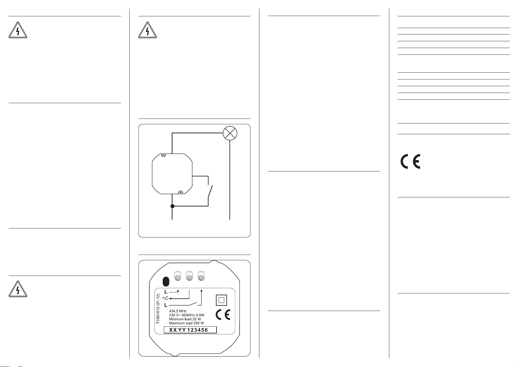
230V / 50 Hz
L‘
L
N
5. Installation
7. Electrical connection
8. Logging DuoFern transmitters on/o
11. Technical Data
Dur ing both i nstall ation an d disman tling o f t he
DuoFern Universal Dimmactuator (fm) there is a risk of
fatal electric shocks.
Observe the safety instructions for electrical connection in
chapter 7.
The DuoFern Universal Dimmactuator (fm) is intended for ush mounting.
We recommend using a deep box.
You require for installation a 58 mm ush-mounted box.
NOTE
In order to ensure optimal operation, the DuoFern Universal Dimmactuator
(fm) should not be installed on a metallic base or near metal objects.
5.1 Installation procedure
1. Switch o the mains (at the fuse box or consumer unit).
2. Electrical connection in accordance with chapter 7. / 7.1.
3. Reconnect the mains power.
4. Register the DuoFern Universal Dimmactuator (fm) in the DuoFern
radio network, see chapter 8.
5. Switch o the mains voltage again after registration has
been successfully completed.
6. Insert the DuoFern Universal Dimmactuator (fm) in the ushmounted box and lay the connecting cables in the box.
ATTENT ION
◆ Avoid bending the antenna too far as it could otherwise break o.
7. Mount the cover plate on the ush-mounted box.
8. Reconnect the mains power.
9. The DuoFern Universal Dimmactuator (fm) automatically detects the
connected load.
The DuoFern Universal Dimmactuator (fm) is then ready for operation after
approx. 15 seconds.
6. Dismantling
1. Switch o the mains (at the fuse box or consumer unit).
2. Open the ush-mounted box.
3. Disconnect the D uoFern Universal Dimmactuator (fm) and
remove it from the ush-mounted box..
7. Electrical connection
Safety instructions
There is a risk of fatal electric shocks.
The elec trical connection and all work on electrical systems
must only be carried out by a qualied electrician in accordance
with the connection instructions in these operating instructions.
◆ Carry out all installation and connection work only in an
isolated, deenergised state.
◆ Disconnect all phases of the mains power supply cable and
secure it to prevent reconnection.
◆ Check that the system is dead.
◆ Prior to con nectin g, co mpare the info rmation abo ut
voltage/frequency on the device with those of the local
electrical grid operator.
Incorrect wiring may lead to short-circuits and
destruction of the device.
◆ Observe the sequence of connector pin assignments in the
wiring diagram and on the type plate.
Connection instructions for local operation
You can use a switch to enable local control via the 230 V control input. The
maximum permissible cable length amounts to 10 m.
IMPOR TANT
When the control input is used, the switch and the actuator must be connected to the same phase (L). If the control input is not used, then nothing
may be connected to the terminal!
7.1 Wiring diagram
Consumer
DuoFern
Universal
Dimmactuator (fm)
7.2 Connection terminals
You must assign every required DuoFern transmitter to the DuoFern Universal
Dimmactuator (fm) in order that the Universal Dimmactuator (fm) can be
controlled with a DuoFern transmitter. You can assign max. 20 DuoFern
transmitters, e. g. DuoFern manual transmitter Standard to the Universal
Dimmactuator (fm).
1. Switch the desired DuoFern transmitter to connect-/ disconnect
mode (please refer to the corresponding operating instructions).
2. Press the “Connect (log-on)” or “Disconnect (log-o)” button
on the upper side of the housing.
3. The Universal Dimmactuator (fm) then transmits either a
log-on or log-o signal. Registering mode remains active for
120 seconds.
4. If registration is successf ul, the indicator li ght will light up
green constantly.
5. Register the next DuoFern transmitter. In order to do so, repeat
steps 1 to 3, or else terminate Logging on/o.
NOTE
The indicator LED lights up red if the registration process fa ils, for
example if:
◆ 20 DuoFern transmitters have already been registered.
◆ A unsuitable device (e. g. other DuoFern actuator) is registered.
◆ An attempt is made to log-o a DuoFern transmitter that is not
logged-on.
9. Logging on and o per radio code
You can control the DuoFern Universal Dimmactuator (fm) directly using
the radio code in order, for example, to be able to connect further DuoFern
transmitters to the Universal Dimmactuator (fm) after installation. You will
nd the radio code on the enclosed label and on the rear side of the Universal
Dimmactuator (fm).
1. Enter the Universal Dimmac tuator (fm)’s radio code in menu
“2.2. Radio code” of the DuoFern central operating unit.
2. Ac tivate an d c onfir m c onnec t / di sconne ct mode for th e
Universal Dimmactuator (fm) on the DuoFern central operating
unit.
3. Call up menu “2. Radio Settings”.
4. Act ivate functi on “2.1 Connect/disconnec t” on the D uoFern
central operating unit.
5. Connect the Universal D immactuator (fm) with the DuoFern
central operating unit or disconnect from the DuoFern central
operating unit.
6. As sign t he Un iversal Dimmactu ator (f m) to the respec tive
groups / member numbers and names.
A more detailed description can be found in the DuoFern central operat-
ing unit’s operating manual.
10. Deleting all settings (Reset)
1. Press the Disconnect button until the indicator LED lights up
continuously red.
2. All of the settings are deleted and the logged in DuoFern transmitters are automatically logged o.
3. All of the settings will be reset to the factory settings. Subsequently, the DuoFern Universal Dimmac tuator (fm) will be
reset to its delivery setting.
Supply voltage: 230 V / 50 Hz
Standby consumption: < 0,5 W
Minimum load: 25 W
Maximum load: 250 W
Transmitting power: 10 mW
Range in a building: approx. 30 m (depending on
construction)
Range outside: approx. 100 m
Transmission frequency: 434.5 MHz
Maximum no. of DuoFern transmitters: 20
Permissible ambient temperature: + 5 °C to + 40°C
Dimensions (Diameter / Hight): 48 mm / 24 mm
Dimming of: - Ohmic loads (e. g. bulbs)
- Leading-edge phase control *
- Trailing-edge phase control *
* transformer
12. CE Mark and EC Conformity
The DuoFern Universal Dimmactuator (fm), (Item no. 3500 04 64) complies
with the requirements of the current European and national directives.
1999/5/EC R&TTE direc tive
2006/95/EC Low voltage directive
2004/108/EC EMC directive
Conformity has been veried. The corresponding declarations and documentation are available on le at the manufacturer’s premises.
13. Warranty conditions
RADEMACHER Geräte-Elektronik GmbH provides a 24-month warranty for new systems that
have been installed in compliance with the installati on instructions. All construction fault s,
material defe cts and manufa cturing defec ts are covered by the warranty.
The following are not covered by the warranty:
◆ Incorrect ttin g or installation
◆ Non-observan ce of the instal lation and operati ng instructions
◆ Improper operation or wear and tear
◆ External inue nces, such as impa cts, knocks or we athering
◆ Repairs and mod ications by third party, unauthori sed persons
◆ Use of unsuitabl e accessories
◆ Damage caused b y unacceptable exces s voltage (e.g. stroke o f lightning)
◆ Operational malfunc tions caused by radi o frequ ency overlapping and other such
radio inter ference
RADEMACHER shall remedy any defects, which occur wit hin the warranty period free of
charge either by repair or by rep lacement of the a ected parts or by su pply o f a new
replacement unit or one to the same value. There is no genera l extension of the original
warranty perio d by delivery of a replaceme nt or by repair as per the terms of the warranty.
RADEMA CHER
Geräte-Elektronik GmbH & Co. KG
Buschkamp 7
46414 Rhede (Germany)
info@rademacher.de
www.rademacher.de
Service:
Hotline 01805 933-171*
Fax +49 2872 933-253
service@rademacher.de
* 14 ct/minute on a German landline
operated by DT AG / Mobile charges
max. 42 cents/minute (Germany only)
Subject to technical modi cations, misprints and
errors. Illus trations not bindi ng.
 Loading...