

Rademacher 35000262 User guide
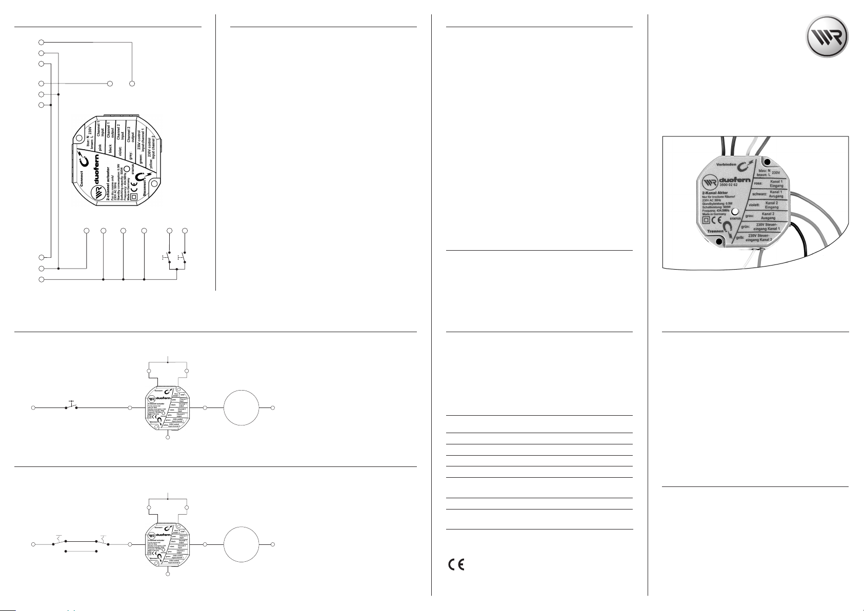
7.1 Wiring diagrams 8. Logging DuoFern transmitters on / o
Consumer 2
Consumer 1
PE N L
green/
L
N
PE
green/
N PE
L
230V / 50 Hz
br
bl
yellow
br
bl
yellow
green/yellow
bl
br
Relay output
Relay output
Channel 2 / (gre y)
Channel 1 / (bla ck)
3500 02 6 2
2-channel universal-actuator 3500 02 62
blue
brown
L
N
violet
pink
Relay input 1
Relay input 2
yellow; 2control input chann el
green; control inpu t channel 1
Channel 1
Channel 2
You must assign every required DuoFern transmitter to the actuator
in order that the actuator can be controlled with a DuoFern transmitter. You
can assign max. 20 DuoFern transmitters (e. g. RolloTron Comfort DuoFern,
DuoFern manual transmitter Standard) etc.) to the actuator.
1. Switch the desired DuoFern transmitter to registering mode
(please refer to the corresponding operating instructions).
2. Use the magnets provided to touch either the “Connect (log-on)”
or “Discon nect (log-o ff)” button on the uppe r si de o f th e
housing.
3. The actuator then transmits either a log-on or log-o signal.
Registering mode remains active for 60 seconds.
4. If registration is successful, the status LED will light up
green constantly.
5. Register the next DuoFern transmitter. In order to do so,
repeat steps 1 to 3, or else terminate registration.
NOTE
The status LED lights up red if the registration process fails, for example if:
- 20 DuoFern transmitters have already been registered.
- A unsuitable device (e. g. other DuoFern actuator) is registered.
- An attempt is made to log-o a DuoFern transmitter that is not
logged-on.
8.1 Logging on and o per radio code
You ca n control the actuator directly using the radio code in order, for
example, to be able to connect further DuoFern transmitters to the actuator
after installation. You will nd the radio code on the enclosed label and on
the rear side of the actuator.
1. Enter the actuat or‘s r adio code in men u „2.2. Radio code“
of the DuoFern central operating unit.
2. Activate and conrm connect / disconnect mode for the
actuator on the DuoFern central operating unit.
3. Call up menu „2. Radio Settings“.
4. Activate function 2.1 Connect/disconnect on the DuoFern
central operating unit.
5. Connect the actuator with the DuoFern central operating unit
or disconnect from the DuoFern central operating unit.
6. Assign the actuator to the respective groups / member
numbers and names.
A more detailed descrip tion can b e foun d in the DuoFern centra l
operating unit‘s operating manual.
9. SET Magnet
NOTE
Set magnet, refer to the enclosed german operating manual. You can carry
out all of the required settings with the magnet stuck on.
Operating and
installation and instructions
DuoFern universal actuator
(2-channel)
Item no. 3500 02 62
VBD 501-3-1 (06.13)
7.2 Installation example
230V / 50 Hz
brown
230V / 50 Hz
brown
Switch / b utton
L
Changeover switch
1
L
230V / 50 Hz
L / brown
L
brown
3500 0262
Control
input
Channel 1
green
brown
N / blue
230V /
50 Hz
L / brown
L
3500 0262
N / blue
2-channel universal actuator 3500 02 62
2
Control
input
Channel 1
green
2-channel universal actuator 3500 02 62
Relay input 1
pink
Relay
output
Channel 1
black
Relay input 1
pink
Relay
output
Channel 1
black
Consumer
1
Consumer
1
Installation with a switch / button
We recommend using a button.
N
blue
Installation with changeover switches
We recommend replacing the cross connection with
several switches connected in parallel.
The corresponding inputs /outputs must be connected for the second channel as per channel 1.
N
NOTE
blue
You can obtain additional example circuits from our
webpage at www.rademacher.de
10. Erase data (reset)
1. Hold the magnets provided against the “Disconnect”
button until the status LED lights up continuously red.
2. All of the registered DuoFern transmitters are logged- o and
all data will be reset to the factory settings. Subsequently, the
DuoFern actuator will be reset to its delivery setting.
11. Technical data
Supply voltage: 230 V / 50 Hz
Standby consumption: 0.5 W
Switching capacity: max. 500 W (per channel)
Protection class: II (only for use in dry areas)
Frequency: 434.5 MHz
Dimensions: Diameter approx. 48 mm /
Height approx. 20 mm
Permissible ambient temperature: -20 °C to + 55 °C
12. CE Mark and EC Conformity
The DuoFern universal actuator (Item no. 3500 02 62 ) complies with the
requirements of the current European and national directives.
1999/5/EC R&TTE directive
Conformity has been veried. The corresponding declaration and documentation are available on le at the manufacturer’s premises.
13. Warranty conditions
RADEMACHER Geräte-Elektronik GmbH provides a 24-month warranty for new systems
that have been installed in compliance with the installation instructions. All construction faults, material defects and manufacturing defects are covered by the warranty.
The following are not covered by the warranty:
◆ Incorrect tting or installation
◆ Non-observance of the installation and operating instructions
◆ Improper operation or wear and tear
◆ External inuences, such as impacts, knocks or weathering
◆ Repairs and modications by third party, unauthorised persons
◆ Use of unsuitable accessories
◆ Damage caused by unacceptable excess voltage (e. g. lightning)
◆ Operational malfunctions c aused by radio frequency overlaps and other such
radio interference
RADEMACHER shall remedy any defects, which occur within the warranty period free
of charge either by repair or by replacement of the aected parts or by supply of a
new replacement unit or one to the same value. There is no general extension of the
original warranty period by delivery of a replacement or by repair as per the terms
of the warranty.
RA DEMA CHE R
Geräte-Elektronik GmbH & Co. KG
Buschkamp 7
46414 Rhede (Germany)
info@rademacher.de
ww w.ra dem ach er. de
Se rvic e:
Ho tlin e 01807 933-171*
Telefax +49 2872 933-253
service@rademacher.de
* 30 seconds free of charge, subsequently 14 cents / minute from German xed
line networks and max. 42 cents / minute from German cellular networks.
Subject to technical modications, misprints and errors excepted. Figures subject to change.
1. General safety instructions
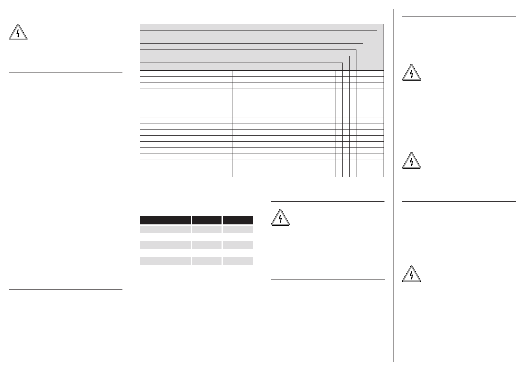
4.1 DuoFern network function table (Conguring for each channel individually.
6. Dismantling
The use of defective equipment can lead to personal
injury and damage to property (elec tric shocks, short
circuiting).
Never use defective or damaged equipment. Please contact
our Customer Service department in the event of faults.
2. Correct usage
Correct usage
Only use the DuoFern universal actuator (Item no. 3500 02 62) for connecting and controlling electrical consumers (e. g. lamps, pond pumps, etc.).
Operating conditions
◆ Only use the DuoFern universal actuator in dry rooms.
◆ For the electrical connection a 230 V/50 Hz power supply, together
with a site-provided isolating device (fuse), must be available at the
installation site.
◆ The installation and operation of the DuoFern radio system and it s
components (e. g. DuoFern universal actuator) is only permitted for those
systems and devices where a malfunction in the transmitter or receiver
would not cause a danger to persons or property or where this risk is
already covered by other safety equipment.
3. Incorrect use
* WR CongTool in c onjunction wit h the DuoFern cen tral operating un it
RolloTron Comfort DuoFern / Troll Comfo rt DuoFern
DuoFern man ual transmitter s tandard
DuoFern wall controller
Function Value range Factory setting
1. Manual operation on / o -
2. Devices-/ Lighting mode Devices- /Lighting mode Lighting mode
3. Manual mode on / o on / o o
4. Automatic timer on / o on / o on
5. Random functio n - -
6. Automatic dawn functio n - -
7. Automatic dawn functio n on / o on / o o
8. Automatic dusk funct ion - -
9. Automatic dusk funct ion on / o on / o o
10. Sun function - -
11. Automatic solar function on / o on / o o
12. Connectivity test - -
13. Connect with radio code - -
14. Reset via radio (3-stage ) - -
15. Single button operation - -
16. Stairwell function on / o o
17. Stairway time (impulse duration) 100 ms - 3276 s 180 seconds
* The „WR CongTool“ software can be downloaded from our website at www.rademacher.de
4.2 Functional description
5. Installation
HomePilot ®
DuoFern envi ronmental sensor
DuoFern cen tral operating un it
● ● ● ●
● ● ●
● ● ●
● ● ●
● ● ● ●
● ● ●
● ● ● ●
● ● ●
● ●
● ● ●
● ● ●
● ●
● ●
● ●
● ●
1. Switch o the mains (at the fuse box or consumer unit).
2. Open the ush-mounted box, disconnect the DuoFern universal
actuator and remove it from the ush-mounted box.
7. Electrical connection
Safety instructions
There is a risk of fatal electric shocks.
◆ The elec trical connecti on an d all work on electri cal
●
systems must only be carried out by a qualied electrician in accordance with the connec tion instructions in
these operating instructions.
◆ Carry out all installation and connection work only in an
isolated, de-energised state.
◆ Disconnect all phases of the mains power supply cable
and secure it to prevent re-connection.
◆ Check that the system is dead.
◆ Prior to connecting, compare the information about
voltage/frequency on the device with those of the local
electrical grid operator.
Incorrect wiring may lead to short-circuits and
destruction of the device.
◆ Observe the sequence of connector pin assignments in
the wiring diagram.
7. Electrical connec tion
Never use the DuoFern radio system and its compo nents (e. g. DuoFern
universal actuator) for remote control of devices and systems with heightened
safety-relevant requirements or a heightened risk of accident. Such u se
would require additional safety equipment. Observe the respective statutory
regulations for the installation of such systems.
IMPOR TANT
Do not install the DuoFern universal actuator outdoors.
4. Brief description
The DuoFern universal actuator (Item no. 3500 02 62) can be used to integrate
and control two electrical consumers (e. g. a lamp and pond pump) within a
DuoFern radio network. This means that many of the functions of the DuoFern
transmitter (e. g. RolloTron Comfort DuoFern, Item no.
Functional characteristics
◆ Connection of up to two electrical consumers.
◆ Each consumer has a local control option available via
two 230 V inputs (e. g. switch or button).
1523 45 11
) can be used.
Overview of switching commands and actions
switching commands * device light
UP ON OFF
STOP OFF OFF
DOWN OFF ON
Automatic dawn function ON OFF
Automatic dusk function OFF ON
* From a DuoFern transmitter (e. g. DuoFern manual transmitter standard)
NOTE
Switching commands can vary depending on the congured mode. Please
refer to the operating instructions for the DuoFern manual central operating unit.
Random function
The actuator can process random function switching commands. If a switching command is received which is to be delayed by the random function,
then processing of the switching command is delayed by up to 30 minutes.
The LED ashes green once per second during the delay period. The random
function works independently for each channel.
During both installation and dismounting of the actuator there is a risk of fatal electric shocks.
Observe the safety instructions for electrical connection in
chapter 7.
The DuoFern universal actuator (Item no. 3500 02 62) is intended for ush
mounting. We recommend using a deep (58 mm) ush-mounted box
NOTE
In order to ensure optimal operation, the DuoFern universal actuator should
not be installed on a metallic base or near metal objects.
5.1 Installation procedure
1. Switch o the mains (at the fuse box or consumer unit).
2. Electrical connection in accordance with chapter 7 / 7.1.
3. Reconnect the mains power.
4. Register the DuoFern universal actuator in the DuoFern radio
network, see chapter 8.
5. Switch o the mains voltage again after registration has
been successfully completed.
6. Insert the DuoFern universal actuator in the ush-mounted
box and lay the connecting cables in the box.
7. Mount the cover on the ush-mounted box.
8. Reconnect the mains power.
Connection instructions for local operation
Switches or buttons can be used in for local operation with the 230 V control
inputs (green and yellow connection leads). The maximum length of lead
may not exceed 10 m.
NOTE
Use a locking roller shutter switch in order to avoid excessive power consumption and excessive heat build-up.
IMPOR TANT
◆ When the control inputs are used, the button and the
actuator must be connected to the same phase (L).
◆ If the control inputs are not used, then you must connect
the control leads to N!
 Loading...