

Rademacher 32160211 User guide

Operating and
installation instructions
DuoFern Wall Controller
Item no.: 3216 02 21 / 3216 02 11
VBD 563-2 (10.12)
1. General safety instructions
The use of defective equipment can lead
to personal injur y and damage to property.
Never use defective or damaged equipment.
Please contact our Customer Service department in this event .
2. Correct usage
Correct usage
Only use the DuoFern wall controller 3216 02 21 / 3216 02 11
for the remote control of:
◆ Shutters / Blinds
◆ Electrical consumers (for instance lighting)
Operating conditions
◆ Only use the DuoFern wall controller in dry rooms.
◆ The installation and operation of the DuoFern radio sys-
tem and its components (e. g. DuoFern tubular motor
actuator) is only permitted for systems and devices
where a malfunc tion in the transmitter or receiver
would not cause a danger to personnel or property or
where this risk is already covered by other safety equipment.
3. Incorrect use
Never use the DuoFern radio system and its components for
the remote control of appliances and systems with increased
safety-relevant requirements or where there is an accident
risk. This would require additional safety equipment. Observe the respective statutory regulations for the installation
of such systems.
IMPORTANT
Do not install the DuoFern wall controller outside.
4. General view
Front of the keypad
Key 1
Left rocker switch
Key 3
Indicator light (red/green LED)
The indicator light is concealed behind the two rocker switches.
Rear of the keypad
Battery compartment with cover
Key 5
Use a thin object that is not too sharp to press this key
(for instance a paperclip).
4.1 Functional description
Use the DuoFern wall controller to manually operate diverse
DuoFern actuators remotely. To do so, connect the DuoFern
wall controller to the required DuoFern network.
Use the two rocker switches to send manual control commands to the connected DuoFern actuators.
A bi-coloured indicator light shows whether the DuoFern
actuators connected to the wall controller have received and
conrmed the control commands. The indicator light is concealed behind the two rocker switches.
Key 2
Right rocker switch
Key 4
4.2. Two operating modes
1. Tubular motor mode
The following control commands are sent in Tubular
motor mode: UP/STOP/DOWN
NOTE
Every DuoFern actuator reacts to these commands. Please additionally read the operating instructions for the DuoFern actuator.
2. Lighting/Devices mode
The following control commands are sent per rocker
switch: ON/OFF
NOTE
◆ The DuoFern actuator is in Tubular motor mode when
it leaves the factory.
◆ The individual channels of an actuator can be distributed
to the two rocker switches in Lighting/Devices mode.
◆ Only the DuoFern actuators that suppor t On/O switch-
ing commands react to the Light/Devices mode (e. g.
the DuoFern universal actuator or the DuoFern socket
actuator.)
4.3 Assignment of control commands to the keys
Key Tubular motor
1
2 STOP ON (channel 2)
3
4 STOP OFF (channel 2)
1 + 2
(5 sec)
1 + 4
(5 sec)
1 + 5
(5 sec)
2 + 3
(5 sec)
2 + 5
(5 sec)
3 + 4
(5 sec)
5
(10 sec)
mode
OPEN (s)
DOWN (t)
Enable wall controller login mode
Switch over between Tubular motor
mode and Lighting/Devices mode
Change direction
of rotation
- - -
Enable wall controller log o mode.
Lighting/
Devices
mode
ON (channel 1)
OFF (channel 1)
Switch over
between
lighting and
devices function
(channel 1)
Clear up
Switch over
between
lighting and
devices function
(channel 2)
Reset
4.4 Overview of models with number of con trollable groups and DuoFern end devices
Item no. Number of
3216 02 21
3216 02 11
groups
1 32
Max. number
of end devices
5. Installation procedure
1. Perform all of the setting s req uired with the
keypad.
2. Select a suitable installation site.
The installation site should preferably be at and free
of dust.
3. Pull one of th e two protec tive films from the
double-sided adhesive strip and press the mount ing frame onto the adhesive strip.
The mounting frame can also be screwed in place with
two screws if need be.
4. Pull the second protective lm from the double sided adhesive strip and press it rmly onto the
base surface.
5. Press the keypad into the mounting frame until it
clicks into place.
NOTE
◆ Fit the antenna, as shown in the Figure, to ensure
the best possible reception.
◆ Avoid bending the antenna too far as it could
otherwise break o.
Mounting frame
6. Finally press the cover frame over the keypa d.
Take care that the antenn a doe s no t bec ome
caug ht a nd damaged. The Duo Fern wall con troller is now ready for operation.
Antenna
Keypad Indicator light
6. Dismantling
1. Dismantle the wall controller in reverse order.
7. Login of DuoFern end devices
You must assign the wall controller to every required
DuoFern actuator so that the DuoFern wall controller can
control a DuoFern actuator.
You can login a maximum of 32 DuoFern actuators at the
wall controller, for instance RolloTron Standard or Comfort
DuoFern; D uoFern actuators (Tubular motor actuator or
universal actuator) etc.
1. Switch the DuoFern actuator to Login
mode (please refer to the correspon ding operating instructions).
2. Switch the wall controller to Login mode.
- To do so, press keys 1 and 2 simultaneously and
hold down for approx. 5 seconds.
3.a The wall controller is in Tubular motor mode
(factory setting)
No further conguration is needed - all of the channels
of an actuator are operated at the same time.
3.b The wall controller is in Lighting/Devices mode.
Every channel of the actuator must be assigned to a
rocker switch. The indicator light will continue to show
orange until all of the channels of an actuator are assigned.
Proceed as follows:
- Key 1 to operate the channel with the left
rocker switch.
- Key 2 to operate the channel with the right
rocker switch.
- Press key 3 or 4 in order not to operate the channel.
NOTE
Refer to the table in chapter 4.3. for the changeover
between Tubular motor mode and Lighting/Devices
mode.
3.c Pay attention to the indicator light:
Green: Login was successful.
Red: Login failed.
4. Login the next DuoFern actuator.
8. Log DuoFern actuators o
10. “Clear up” function
11.2 In Lighting/Devices mode
13. Battery replacement
15. CE Mark and EC Conformity
1. Switch the desired DuoFern actuator to Log o
mode.
2. Switch the wall controller to Log o mode:
To do so, press keys 3 and 4 simultaneously and
hold down for approx. 5 seconds.
3. Pay attention to the indicator light:
Green: Log o was successful.
Red: Log o failed.
9. Reversal of direction of rotation
This function reverses the direction of rotation of tubular
motors or switches the function of switching actuators.
NOTE
◆ The direction of rotation/reversal of function is only
available if precisely one actuator is logged in on the
key. With multichannel actuators, all of the channels
logged in on the key are switched over.
◆ Not every actuator supports this functions, so
please read in the relevant operating instructions for the actuator whether this function is
available.
9.1 Reversing the direction of rotation (key 1)
1. Press keys 1 and 5 simultaneously and hold down
for approx. 5 seconds
2. The direction of rotation and function is changed
on the actuator operated by key 1.
3. Pay attention to the indicator light:
Green: The reversal of the direction of rotation was
successful.
Red The reversal of the direction of rotation
failed.
9.2 Reversing the direction of rotation (key 2)
NOTE
This function is only available in Lighting/Devices
mode
1. Press keys 2 and 5 simultaneously and hold down
for approx. 5 seconds.
2. The direction of rotation and function is changed
on the actuator operated by key 2.
3. Pay attention to the indicator light:
Green: The reversal of the direction of rotation was
successful.
Red The reversal of the direction of rotation was
unsuccessful.
This function logs o all of the registered DuoFern actuators
that are no longer reacting. This could be necessar y with a
faulty unit, for instance, that can no longer be logged o, as
described previously in chapter 8.
NOTE
◆ All battery-operated DuoFern units are not/cannot be
logged o in this way.
◆ Perform the „Reset (delete settings)“ function (cf.
chapter 12) to log o all DuoFern actuators from the
DuoFern wall controller.
10.1 Activate „Clear up“ function
1. Ensure th at yo u ar e i n th e ra dio range of all
DuoFern actuators.
2. Press keys 2 and 3 simultaneously and hold down
for approx. 5 seconds.
3. The DuoFer n wal l c ontrolle r no w tr ansmits a
control signal to all DuoFern actuators logged in.
The units that do not conrm the signal are automatically deleted.
4. Pay attention to the indicator light:
Green: Clear up was successful.
Red: Clear up was unsuccessful.
11. Manual operation
11.1 In Tubular motor mode
1. Press key 1 (s).
Open the roller shutter or „switch on or o“ *
the electrical consumer.
2. Press „STOP “ keys 2 or 4
Stop the roller shutter or switch o the
electrical consumer.
3. Press key 3 (t).
Close the roller shutter or „switch o or on“ *
the electrical consumer.
4. Pay attention to the indicator light:
Green: The switching command has been performed
successfully.
Red The switching command has not yet ended
or an error has occurred.
* depending on the function
Left rocker switch:
1. Press key 1 „ON“ and switch on the electric al
consumer.
2. Press key 3 „OFF“ and switch o the electric al
consumer.
Right rocker switch:
1. Press key 2 „ON“ and switch on the electric al
consumer.
2. Press key 4 „OFF“ and switch o the electric al
consumer.
3. Pay attention to the indicator light:
Green: The switching command has been performed
successfully.
Red The switching command has not yet ended
or an error has occurred.
12. Deleting all settings (Reset)
1. Press key 5 for approx. 10 seconds (with a paper clip, for instance).
2. All of the settings are deleted and the logged in
DuoFern actuators are automatically logged o.
Pay attention to the indicator light:
Red Deletion of the settings was successful.
3. Subsequently, the DuoFern wall c ontroller will
be reset to its delivery setting or to Tubular motor
mode.
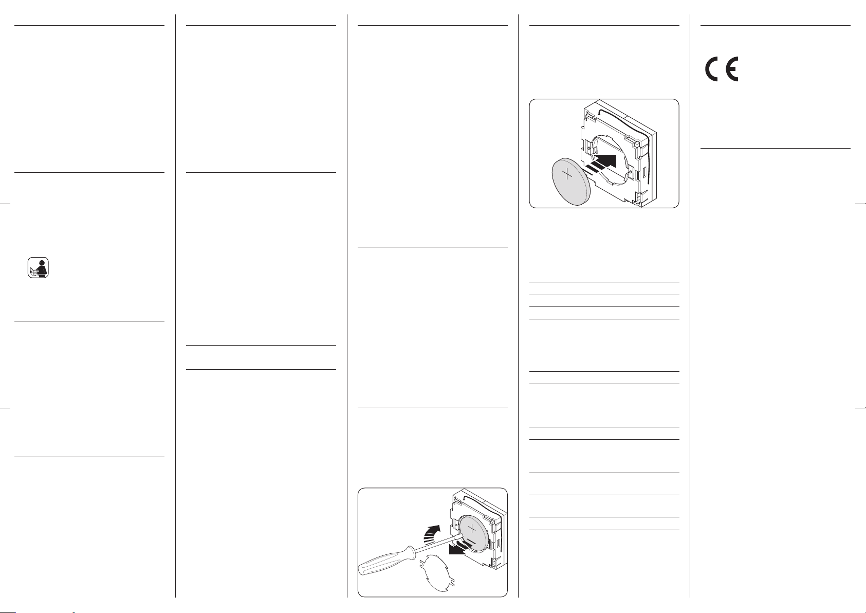
13. Battery replacement
1. Pull the cover frame carefully from the keypad
and then remove the keypad from the mounting
frame.
2. Carefully remove the battery cover with a small
screwdriver.
3. Remove the battery from its compartment and
replace it with a new battery of the same type.
IMPORTANT
When inser ting the battery, pay attention to the correct polarity. The plus pole (+) of the battery must
lie at the outside.
NOTE
Empty batteries are special waste and should not be disposed of with household waste.
14. Technical data
Supply voltage: 3 V DC
Battery type: 3 V / CR 2430
Battery life:
- with normal use up to 2 years
(depending on
switching frequency) with 5 actuations per day
- in Standby: approx. 5 years
Transmitting power: 10 mW
Range:
- in a building (depending
on construction): approx. 30 m
- outside: approx. 100 m
Transmission frequency: 434.5 MHz
Max. number:
- Groups: 1
- DuoFern end units: 32
Permissible ambient
temperature: + 5 °C to + 40 °C
Dimensions:
- Keypad (L x W x H): 40 x 40 x 18 (mm)
Weight: 70 g
The present product complies with the requirements of the
current European and national directives.
1999/5/EC R&TTE directive
Conformity has been veried. The corresponding declarations and documentation are available on le at the manufacturer’s premises.
16. Warranty conditions
RADEMACHER Geräte-Elektronik GmbH provides a 24-month warranty for
new systems that have been installed in compliance with the installation
instructions. All construction faults, material defects and manufacturing
defects are covered by the warranty.
The following are not covered by the warranty:
◆ Incorrect tting or installation
◆ Non-observance of the installation and operating instructions
◆ Improper operation or wear and tear
◆ External inuences, such as impacts, knocks or weathering
◆ Repairs and modications by third party, unauthorised persons
◆ Use of unsuitable accessories
◆ Damage caused by unacceptable excess voltage (e.g. stroke of
lightning)
◆ Operational malfunctions caused by radio frequency overlapping
and other such radio interference
RADEMACHER shall remedy any defects, which occur within the warranty
period free of charge either by repair or by replacement of the aected
parts or by supply of a new replacement unit or one to the same value.
There is no general extension of the original warranty period by delivery of
a replacement or by repair as per the terms of the warranty
RA DEMA CHE R
Geräte-Elektronik GmbH & Co. KG
Buschkamp 7
46414 Rhede (Germany)
info@rademacher.de
ww w.ra dem ach er. de
Se rvic e:
Ho tlin e 01805 933-171*
Telefax +49 2872 933-253
service@rademacher.de
* 14 cent s/minute from a German xed line ne twork
operated by DT AG / Mobile charges max. 42 cents/
minute (applies to Germany only)
Subject to technical modications, misprints and errors.
Illustrations not binding.
 Loading...