

Page 1

User’s Guide User’s Guide User’s Guide User’s Guide User’s Guide
Quantum Scalar i500 Tape Library
Quantum Scalar i500 Tape Library
Scalar i500
6-01210-05 B
Page 2

Scalar i500 User’s Guide, 6-01210-05, Rev. B, May 2010, Made in USA.
Quantum Corporation provides this publication “as is” without warranty of any kind, either express or implied,
including but not limited to the implied warranties of merchantability or fitness for a particular purpose. Quantum
Corporation may revise this publication from time to time without notice.
COPYRIGHT STATEMENT
Copyright 2010 by Quantum Corporation. All rights reserved.
Your right to copy this manual is limited by copyright law. Making copies or adaptations without prior written
authorization of Quantum Corporation is prohibited by law and constitutes a punishable violation of the law.
TRADEMARK STATEMENT
Quantum, the Quantum logo, and Scalar are registered trademarks of Quantum Corporation in the USA and other
countries. LTO and Ultrium are trademarks of Quantum, IBM, and HP in the USA and other countries.
All other trademarks are the property of their respective companies.
Page 3

Contents
Preface 1
Chapter 1 Description 10
Intelligent Storage............................................................................................ 11
Library Configuration..................................................................................... 11
Modules............................................................................................................. 15
Control Module......................................................................................... 16
Expansion Modules.................................................................................. 16
Stackability ................................................................................................ 16
Front Panel Components ................................................................................ 18
Access Door ............................................................................................... 18
I/E Station ................................................................................................. 19
Operator Panel .......................................................................................... 19
Front Power Button .................................................................................. 20
Back Panel Components ................................................................................. 20
Rear Power Switches................................................................................ 22
Power System............................................................................................ 22
Library Control Blade .............................................................................. 24
Fibre-Channel Input/Output Blades..................................................... 26
Robotic System and Barcode Scanner........................................................... 29
Tape Drive Support ......................................................................................... 30
Scalar i500 User’s Guide iii
Page 4

Library Features ...............................................................................................31
User Interface ............................................................................................ 31
Partitions .................................................................................................... 31
Control Path Modification....................................................................... 32
Support for WORM .................................................................................. 32
Licensable Features.......................................................................................... 32
Chapter 2 Understanding the User Interface 33
Common User Interface Elements................................................................. 34
System Summary and Subsystem Status .............................................. 36
Home Page................................................................................................. 37
Operator Panel..................................................................................................38
Operator Panel Keypads.......................................................................... 38
Operator Panel Indicates Intervention Required ................................. 38
Web Client ........................................................................................................38
Menu Trees ....................................................................................................... 39
User Privileges.................................................................................................. 45
User Access ....................................................................................................... 46
Chapter 3 Configuring Your Library 47
About the Setup Wizard ................................................................................. 48
Using the Default Administrator Account............................................ 49
Completing the Library Configuration With Menu Commands....... 49
Using the Setup Wizard .................................................................................. 50
Default Configuration Settings............................................................... 52
Setup Wizard Tasks.................................................................................. 52
Logging On to the Web Client ....................................................................... 54
Managing the Network................................................................................... 54
Modifying Network Settings................................................................... 54
Enabling SSL.............................................................................................. 57
Configuring SNMP Settings on the Library.......................................... 58
Working With Partitions................................................................................. 62
Automatically Creating Partitions ......................................................... 64
Manually Creating Partitions.................................................................. 65
Mixing Tape Drive Vendor Types Within Partitions .......................... 68
Modifying Partitions ................................................................................ 68
Deleting Partitions .................................................................................... 69
Changing Partition Access ......................................................................70
Scalar i500 User’s Guide iv
Page 5

Taking a Partition Online or Offline ...................................................... 70
Disabling/Enabling Manual Cartridge Assignment ........................... 71
Configuring Cleaning Slots ............................................................................ 72
Configuring I/E Station Slots.........................................................................74
Configuring Zero I/E Station Slots ........................................................76
Setting Tape Drive Parameters ...................................................................... 77
Working With Control Paths.......................................................................... 79
Obtaining and Installing a License Key........................................................ 81
About License Keys ..................................................................................82
Viewing Licenses and License Keys....................................................... 83
Obtaining a License Key .......................................................................... 83
Applying a License Key...........................................................................84
Setting Customer Contact Information......................................................... 85
Configuring the Library E-mail Account ..................................................... 85
Working With RAS E-mail Notifications......................................................87
Creating RAS E-mail Notifications ........................................................ 88
Modifying RAS E-mail Notifications..................................................... 89
Deleting RAS E-mail Notifications......................................................... 89
Working With User Accounts........................................................................ 89
Local Authentication vs. Remote Authentication ................................ 90
About Local User Accounts..................................................................... 90
Creating Local User Accounts ................................................................ 90
Modifying Local User Accounts............................................................. 91
Deleting Local User Accounts................................................................. 92
Configuring LDAP ...................................................................................92
Configuring Kerberos .............................................................................. 95
Setting the Date, Time, and Time Zone ........................................................ 97
Setting the Date and Time Manually ..................................................... 98
Setting the Date and Time Using the Network Time Protocol ..........98
Setting the Time Zone .............................................................................. 99
Setting Daylight Saving Time ................................................................. 99
Working With FC I/O Blades ......................................................................100
Configuring FC I/O Blade Ports .......................................................... 101
FC I/O Blade Internal Virtual Port for Medium Changers .............. 102
Configuring FC I/O Blade Channel Zoning....................................... 102
Managing FC Hosts and Host Mapping .............................................104
Enabling/Disabling FC Host Mapping ............................................... 104
Viewing FC Host Information .............................................................. 105
Creating, Modifying, and Deleting an FC Host Connection............ 105
Host Mapping - Overview..................................................................... 107
Host Mapping Vs. Channel Zoning..................................................... 108
Configuring Host Mapping................................................................... 108
Configuring FC Host Port Failover......................................................110
Scalar i500 User’s Guide v
Page 6

Repairing and Enabling a Failed Target Port ..................................... 112
Working With Data Path Conditioning...............................................113
Configuring Library Security Settings........................................................ 115
Configuring the Internal Network .............................................................. 116
Configuring System Settings........................................................................ 116
Configuring Operator Panel Display Settings ........................................... 120
Registering the Library.................................................................................. 120
Chapter 4 Advanced Reporting 121
About the Advanced Reporting License .................................................... 122
Working With Advanced Reporting Reports ............................................ 123
Configuring the Drive Resource Utilization Report.......................... 123
Configuring the Media Integrity Analysis Report............................. 125
Using Advanced Reporting Templates ............................................... 127
Loading and Reloading Advanced Reporting Data ..........................128
Deleting Advanced Reporting Data..................................................... 128
Saving and E-mailing Report Data Files ............................................. 129
Configuring and Viewing the Media Security Log...................................129
Viewing the Media Usage Log..................................................................... 130
Automatically E-mailing Advanced Reporting Reports and Logs......... 131
Chapter 5 Capacity on Demand 133
Chapter 6 Storage Networking 135
About the Storage Networking License...................................................... 136
Configuring Control Path Failover..............................................................136
Configuring Host Access .............................................................................. 137
Registering a Host for Host Access...................................................... 138
Enabling Tape Drives for Host Access ................................................139
Mapping a Host to Tape Drives and Partitions..................................140
Modifying a Host.................................................................................... 141
Deleting a Host........................................................................................ 141
Scalar i500 User’s Guide vi
Page 7

Chapter 7 Encryption Key Management 142
About the EKM License ................................................................................ 143
Configuring Quantum Encryption Key Manager (Q-EKM) or
Scalar Key Manager (SKM) on the Library......................................... 144
Step 1: Upgrade Firmware..................................................................... 144
Step 2: Install the EKM License Key on the Library .......................... 144
Step 3: Install Q-EKM/SKM on a Server or Servers.......................... 144
Step 4: Configure Encryption Settings and Key Server Addresses. 145
Step 5: Configure Partition Encryption ............................................... 147
Step 6: Run EKM Path Diagnostics ...................................................... 149
EKM Path Diagnostics................................................................................... 150
Differences Between Manual and Automatic EKM Path
Diagnostics ....................................................................................... 151
Using Manual EKM Path Diagnostics ................................................. 152
Using Automatic EKM Path Diagnostics ............................................ 153
Viewing Tape Drive Encryption Settings................................................... 154
Scalar Key Manager Functions Available on the Library ........................ 154
Importing TLS Certificates ....................................................................155
Sharing Encrypted Tape Cartridges..................................................... 158
Exporting Encryption Certificates........................................................ 159
Importing Encryption Certificates ....................................................... 159
Exporting Data Encryption Keys.......................................................... 160
Importing Data Encryption Keys ......................................................... 161
Accessing the SKM Server Logs ........................................................... 162
Using the SKM Encryption Key Import Warning Log...................... 162
Chapter 8 Running Your Library 164
Logging In....................................................................................................... 165
Logging In When LDAP or Kerberos is Enabled ............................... 165
Logging Out.................................................................................................... 166
Understanding the Location Coordinates.................................................. 166
Modules.................................................................................................... 167
Columns ................................................................................................... 168
Slots........................................................................................................... 168
Tape Drives.............................................................................................. 168
Fibre Channel I/O Blades...................................................................... 168
Power Supplies........................................................................................ 168
Performing Media Operations ..................................................................... 169
Importing Media..................................................................................... 170
Bulk Loading ........................................................................................... 174
Scalar i500 User’s Guide vii
Page 8

Moving Media......................................................................................... 175
Exporting Media ..................................................................................... 177
Loading Tape Drives..............................................................................178
Unloading Tape Drives.......................................................................... 179
Taking a Tape Drive Online or Offline................................................ 180
About Cleaning Tape Drives........................................................................ 181
Enabling AutoClean ............................................................................... 182
Viewing the Cleaning Count................................................................. 183
Using Valid Cleaning Media................................................................. 183
Importing Cleaning Media....................................................................183
Exporting Cleaning Media ....................................................................185
Manually Cleaning Tape Drives...........................................................186
About Tape Drive Operations...................................................................... 188
Locking and Unlocking the I/E Stations....................................................188
Controlling FC I/O Blade Power.................................................................189
Shutting Down or Restarting the Library................................................... 190
Chapter 9 Getting Information 192
Viewing Information About the Scalar i500............................................... 193
Viewing System Information .......................................................................194
Viewing the Library Configuration............................................................. 195
Viewing Network Settings............................................................................ 198
Viewing Logged-in Users ............................................................................. 198
Viewing Slot Information .............................................................................199
Viewing, Saving, and E-mailing Library Logs .......................................... 200
Viewing FC I/O Blade Information ............................................................202
Viewing FC I/O Blade Port Information.................................................... 203
Chapter 10 Updating Library and Tape Drive Firmware 204
Upgrading Library Firmware ...................................................................... 204
Updating Tape Drive Firmware ..................................................................207
Using an Image File to Upgrade Tape Drive Firmware.................... 207
Downgrading IBM LTO-4 Tape Drive Firmware ..............................208
Autoleveling Tape Drive Firmware ............................................................209
Uploading Tape Drive Firmware Used in Autoleveling .................. 209
Deleting Tape Drive Firmware Used in Autoleveling ...................... 210
Scalar i500 User’s Guide viii
Page 9

Chapter 11 Installing, Removing, and Replacing 211
Taking the Library Online/Offline ............................................................. 213
Taking a Library Online.........................................................................213
Taking a Library Offline ........................................................................ 213
Cabling the Library........................................................................................213
Specific Instructions for LTO-5 Tape Drives....................................... 214
Connecting Library SCSI Cables to Hosts........................................... 217
Connecting Library FC Cables Directly to Host.................................220
Connecting Library FC Cables to FC I/O Blades............................... 224
Recommended Library Cabling for FC I/O Blades........................... 231
Connecting Library SAS Cables Directly to Host .............................. 233
Cable Management Guidelines.................................................................... 237
Cable Management Kit .......................................................................... 237
Managing Power Cords ......................................................................... 239
Managing Ethernet Cables ....................................................................242
Installing a Stand-Alone 5U Control Module............................................246
Installing a New Multi-Module Library Configuration........................... 247
Preparing to Install a Multi-Module Library...................................... 248
Installing the Expansion Module ......................................................... 252
Installing the Control Module...............................................................256
Preparing to Use the Multi-Module Library.......................................256
Adding Expansion Modules to an Existing Library................................. 258
Preparing to Install an Additional Expansion Module..................... 260
Unstacking the Existing Modules.........................................................262
Installing the New 9U Expansion Module.......................................... 266
Preparing to Use the Library................................................................. 273
Preparing to Remove or Replace a Module ............................................... 276
Permanently Removing Expansion Modules From an Existing
Library ...................................................................................................... 284
Removing the Expansion Module........................................................285
Preparing to Use the New Library Configuration............................. 290
Replacing the Control Module..................................................................... 296
Removing the Control Module............................................................. 296
Replacing the Control Module..............................................................301
Preparing to Use the Control Module ................................................. 305
Replacing an Expansion Module.................................................................305
Removing the 9U Expansion Module.................................................. 307
Replacing the 9U Expansion Module ..................................................311
Preparing to Use the 9U Expansion Module ......................................317
Removing and Replacing the Library Control Blade and LCB
Compact Flash Card............................................................................... 319
Scalar i500 User’s Guide ix
Page 10

Replacing the LCB and LCB Compact Flash Card............................. 319
Replacing the LCB While Retaining the Old Compact Flash Card. 322
Adding, Removing, and Replacing Power Supplies ................................324
Adding a Redundant Power Supply.................................................... 324
Permanently Removing a Redundant Power Supply ....................... 325
Removing and Replacing a Power Supply ......................................... 326
Installing the Library in a Rack.................................................................... 327
Preparing for Installation....................................................................... 328
Installing the Rackmount Shelves ........................................................332
Preparing Your Library for Rack Installation.....................................335
Installing the Bottom Module in the Rack .......................................... 336
Installing Additional Modules Into the Rack ..................................... 338
Adding, Removing, and Replacing Tape Drives....................................... 346
Adding a Tape Drive.............................................................................. 346
Permanently Removing a Tape Drive .................................................347
Removing and Replacing a Tape Drive............................................... 348
Adding, Removing, and Replacing FC I/O Blades .................................. 350
Read This First: Complete Installation Steps......................................352
Adding an FC I/O Blade .......................................................................354
Removing an FC I/O Blade................................................................... 358
Replacing an FC I/O Blade ................................................................... 359
Adding, Removing, and Replacing the FC I/O Fan Blade ...................... 360
Adding an FC I/O Fan Blade................................................................ 361
Removing an FC I/O Fan Blade ...........................................................362
Replacing an FC I/O Fan Blade............................................................363
Preparing the Library for Moving or Shipping ......................................... 364
Chapter 12 Troubleshooting 366
About RAS Tickets.........................................................................................367
Viewing RAS Tickets.............................................................................. 368
Resolving RAS Tickets .......................................................................... 369
Capturing Snapshots of Library Information ............................................ 370
Saving and E-mailing the Library Configuration Record........................ 371
E-mailing the Configuration Record....................................................372
Saving the Configuration Record......................................................... 373
Saving and Restoring the Library Configuration...................................... 373
Saving the Library Configuration ........................................................ 374
Restoring the Library Configuration and Library Firmware........... 374
Troubleshooting “Library Not Ready” Messages..................................... 375
Duplicate Devices Discovered ..................................................................... 376
Duplicate Medium Changers Discovered.................................................. 376
Scalar i500 User’s Guide x
Page 11

Identifying Tape Drives ................................................................................ 377
Retrieving Tape Drive Logs.......................................................................... 379
Retrieving Tape Drive Sled Logs................................................................. 380
Identifying FC I/O Blades............................................................................381
Permanently Removing FC I/O Blades...................................................... 381
Resetting FC I/O Blade Ports....................................................................... 382
Viewing and E-Mailing the Command History Logs............................... 383
Interpreting LEDs .......................................................................................... 384
LCB and FC I/O Blade LEDs ................................................................ 384
Amber LED on the LCB and FC I/O Blade ........................................385
Ethernet Hub Port LEDs on the LCB ...................................................386
Servicing the LCB Based on LED Status.............................................. 386
Fibre Port Link LED on FC I/O Blades ............................................... 386
FC I/O Fan Blade LED........................................................................... 387
Tape Drive LEDs.....................................................................................388
Fibre Port Link LED on Tape Drives....................................................389
Power Supply LEDs ...............................................................................390
Using the Installation Verification Test ...................................................... 391
Viewing the IVT Logs ............................................................................ 394
Saving and E-mailing the IVT Logs ..................................................... 394
Running Library Demo.......................................................................... 394
Configuring the Internal Network .............................................................. 395
Library Diagnostics........................................................................................ 396
Drive Diagnostics...........................................................................................397
Drive Tests ...............................................................................................397
Media Tests..............................................................................................398
Robotics Diagnostics...................................................................................... 399
Chapter 13 Working With Cartridges and Barcodes 400
Handling Cartridges Properly .....................................................................401
Write-Protecting Cartridges ......................................................................... 402
Barcode Requirements ..................................................................................402
Installing Barcode Labels..............................................................................404
Appendix A Library Specifications 405
Supported Components................................................................................ 405
System Requirements.................................................................................... 406
Library Capacity.............................................................................................407
Scalar i500 User’s Guide xi
Page 12

Environmental Requirements ......................................................................408
Electrical Requirements ................................................................................ 408
Dimensions ..................................................................................................... 409
Component Weights......................................................................................409
Library Power Consumption and Heat Output ........................................ 410
Appendix B TapeAlert Flag Descriptions 412
Glossary 422
Scalar i500 User’s Guide xii
Page 13

Tables
Table 1 Web Client Menus...................................................................... 41
Table 2 Operator Panel Menus............................................................... 43
Table 3 Number of Partitions Supported ............................................. 63
Table 4 Number of I/E Station Slots Available
Table 5 Control Path Assignment During Partition Crea
Table 6 Available Slots and COD Upgrades Per Configuration..... 134
Table 7 Rackmount Kit Contents......................................................... 328
Table 8 Rack Ear Kit Contents.............................................................. 330
Table 9 LED Color and Blade Status ................................................... 385
Table 10 Amber LED Actions................................................................. 386
Table 11 LCB Ethernet Hub Link Activity ........................................... 386
Table 12 Fibre Port Link LED on FC I/O Blade
Table 13 Fan Blade Status ....................................................................... 387
Table 14 Tape Drive Activity.................................................................. 389
Table 15 Fibre Port Link Status ............
Table 16 Power Supply Status................................................................ 391
Scalar i500 User’s Guide xiii
............................................... 390
...
................................ 75
...
tion ........... 79
................................. 387
.
Page 14

Table 17 TapeAlert Flag Severity Codes............................................... 412
Table 18 TapeAlert Flag Descriptions ................................................... 413
Scalar i500 User’s Guide xiv
Page 15

Figures
Figure 1 5U Library Configuration (Standalone Control Module) .... 12
Figure 2 14U Library Configuration (5U Control
Plus One 9U Expansion Module).......
Module
...................................... 13
Figure 3 23U Library Configuration (5U Control
Plus Two 9U Expansion Modules) .......................................... 14
Figure 4 Base Systems Plus Expansion Modules .................................. 17
Figure 5 Front Panel Components .......................................................... 18
Figure 6 Back Panel Components............................................................ 21
Figure 7 Power Supply LEDs................................................................... 24
Figure 8 Library Control Blade ...............
Figure 9 FC I/O Blade............................................................................... 28
Figure 10 FC I/O Fan Blade ....................................................................... 29
Figure 11 Operator Panel User Interface.................................................. 35
Figure 12 Web Client User Interface......................................................... 35
Figure 13 Report Data Buttons...............
Figure 14 Saving and E-mailing the Report
Figure 15 Library Location Coordinates .
Figure 16 Library Configuration Report .
Scalar i500 User’s Guide xv
.............................................. 26
...
...
............................................... 128
Data ................................. 129
............................................... 167
............................................... 196
Module
Page 16

Figure 17 HP LTO-5 Dual Port Fibre Channel Tape Drive.................. 215
Figure 18 HP LTO-5 Single Port SAS Tape Drive .................................215
Figure 19 IBM LTO-5 Single Port Fibre Channel Tape Dr
Figure 20 Stand-Alone 5U Control Module SCSI Cabling
ive.............. 216
................... 217
Figure 21 Multi-Module SCSI Cabling ................................................... 218
Figure 22 Stand-Alone Control Module Fibr
e Channel Cabling ........ 221
Figure 23 Multi-Module Fibre Channel Cabling...................................222
Figure 24 FC I/O Blade............................................................................. 226
Figure 25 FC With I/O Blade Cabling .................................................... 227
Figure 26 Stand-Alone Control Module SAS Cabling.......................... 234
Figure 27 Multi-Module SAS Cabling..................................................... 235
Figure 28 Power Cord Management....................................................... 241
Figure 29 Ethernet Cable Management .................................................. 244
Figure 30 Cable Management, All Cables..
...
......................................... 245
Figure 31 Recommended Module Locations ......................................... 251
Figure 32 Y-Rail in Unlocked, Functional Posi
Figure 33 Cover Plate Location After Adding an
tion...............................255
Expansion
Module....................................................................................... 268
Figure 34 Library Configuration Example 1
.......................................... 278
Figure 35 Library Configuration Example 2
Figure 36 Cover Plate Location After Rem
.......................................... 281
oving an Expansion
Module....................................................................................... 290
Figure 37 FC I/O Blade and Fan Blade Bays in an Expansion
Module....................................................................................... 351
Figure 38 Location of Tape Drive LEDs ................................................. 388
Scalar i500 User’s Guide xvi
Page 17

Preface
Audience
Purpose
Product Safety Statements
This guide is intended for anyone interested in learning about or anyone
who needs to know how to install, configure, and operate the
Scalar® i500 library. Be aware that administrator level privileges are
required to configure many of the features described in this guide.
This guide contains information and instructions necessary for the
normal operation and management of the Scalar i500 library, including:
• Installing the library
• Basic library operations
• Operator commands
• Troubleshooting
This product is designed for data storage and retrieval using magnetic
tapes. Any other application is not considered the intended use. Quantum
will not be held liable for damage arising from unauthorized use of the
product. The user assumes all risk in this aspect.
This unit is engineered and manufactured to meet all safety and
regulatory requirements. Be aware that improper use may result in bodily
injury, damage to the equipment, or interference with other equipment.
Scalar i500 User’s Guide 1
Page 18
Preface
Warning: Before operating this product, read all instructions and
warnings in this document and in the System, Safety, and
Regulatory Information Guide. The System, Safety, and
Regulatory Information Guide is located on the Scalar i500
Documentation, Training, and Resource CD.
Scalar i500 User’s Guide 2
Page 19
Preface
Mercury State m e nt
Projectors, LCD displays, and some multifunction printers may
use lamp(s) that contain a small amount of mercury for energyefficient lighting purposes. Mercury lamps in these products
are labeled accordingly. Please manage the lamp according to
local, state, or federal laws. For more information, contact the Electronic
Industries Alliance at www.eiae.org
information check www.lamprecycle.org
Scalar i500 User’s Guide 3
. For lamp-specific disposal
.
Page 20
Disposal of Electrical and
Electronic Equipment
Preface
This symbol on the product or on its packaging
indicates that this product should not be disposed
of with your other waste. Instead, it should be
handed over to a designated collection point for
the recycling of electrical and electronic
equipment. The separate collection and recycling
of your waste equipment at the time of disposal
will help to conserve natural resources and ensure
that it is recycled in a manner that protects human
health and the environment. For more information
about where you can drop off your waste
equipment for recycling, please visit our web site
at: http://www.quantum.com/AboutUs/weee/Index.aspx
or contact
your local government authority, your household waste disposal service
or the business from which you purchased the product.
Document Organization
This document is organized as follows:
• Chapter 1,
Description, describes basic library configurations and
features.
• Chapter 2,
Understanding the User Interface, discusses the operator
panel and the web client, and the features available on each.
• Chapter 3,
Configuring Your Library, explains how to configure your
library for use.
• Chapter 4,
Advanced Reporting, describes the features available with
the Advanced Reporting license.
• Chapter 5,
Capacity on Demand, describes how to purchase
additional slot capacity for the library.
• Chapter 6,
Storage Networking, describes the features available with
the Storage Networking license.
• Chapter 7,
Encryption Key Management, describes the features
available with the Encryption Key Management license.
• Chapter 8,
Running Your Library, explains how to perform library,
tape drive, and media operations.
Scalar i500 User’s Guide 4
Page 21

Preface
• Chapter 9, Getting Information, explains how to use the library’s
built-in reports to get information you need.
Notational Conventions
• Chapter 10,
Updating Library and Tape Drive Firmware, explains
how to update library and tape drive firmware.
• Chapter 11,
Installing, Removing, and Replacing, provides
instructions on how to install, remove, and replace hardware
components in the library, including modules, tape drives, power
supplies, and cables.
• Chapter 12,
Troubleshooting, describes the library’s diagnostic
reporting system (RAS tickets) and how to use it. It also describes a
number of diagnostic tests you can run to troubleshoot problems.
• Chapter 13,
Working With Cartridges and Barcodes, provides
cartridge handling guidelines.
• Appendix A,
• Appendix B,
Library Specifications, lists the library’s specifications.
TapeAlert Flag Descriptions, describes of all the
TapeAlerts you may see listed in RAS tickets and reports on your
library.
This document concludes with a glossary.
This manual uses the following conventions:
Note: Notes emphasize important information related to the main
topic.
Caution: Cautions indicate potential hazards to equipment or data.
Warning: Warnings indicate potential hazards to personal safety and
are included to prevent injury.
This manual uses the following:
• Right side — Refers to the right side as you face the component being
described.
• Left side — Refers to the left side as you face the component being
described.
Scalar i500 User’s Guide 5
Page 22

Preface
Related Documents
Documents related to the Scalar i500 are shown below. For the most up to
date product information and documentation, see:
http://www.quantum.com/ServiceandSupport/Index.aspx
Document No. Document Title Document Description
6-01741-xx Scalar i500 Getting
Started Guide
6-01317-xx Quantum Scalar
Intelligent Libraries
SMI-S Reference Guide
6-01370-xx Scalar i500 Tape
Library Basic SNMP
Reference Guide
6-00676-xx Quantum SNC
Firmware 4 and 5
Reference Guide
Provides basic cabling and
setup instructions.
Provides an interface
standard that can be used
in a SAN environment.
Describes information you
can obtain from the Scalar
i500 library SNMP.
Provides information about
the Storage Network
Controller, an optional
component that provides
Fibre-Channel to FibreChannel connectivity.
6-01385-xx Scalar i500 Unpacking
Unpacking instructions.
Instructions (5U)
6-01524-xx Scalar i500 Unpacking
Unpacking instructions.
Instructions (9U)
6-01525-xx Scalar i500 Unpacking
Unpacking instructions.
Instructions (14U)
6-01378-xx Scalar i500 Release
Notes
Describes changes to your
system or firmware since
the last release, provides
compatibility information,
and discusses any known
issues and workarounds.
Refer to the appropriate product manuals for information about your
tape drive and cartridges.
Scalar i500 User’s Guide 6
Page 23

Preface
SCSI-2 Specification 0
The SCSI-2 communications specification is the proposed American
National Standard for information systems, dated March 9, 1990. Copies
may be obtained from:
Global Engineering Documents
15 Inverness Way, East
Englewood, CO 80112
(800) 854-7179 or (303) 397-2740
Contacts
Quantum company contacts are listed below.
Quantum Corporate Headquarters
To order documentation on the Scalar i500 or other products contact:
Quantum Corporation (Corporate Headquarters)
1650 Technology Drive, Suite 700
San Jose, CA 95110-1382
Technical Publications
To comment on existing documentation send e-mail to:
doc-comments@quantum.com
Quantum Home Page 0
Visit the Quantum home page at:
http://www.quantum.com
0
0
Scalar i500 User’s Guide 7
Page 24

Preface
Getting More Information or
Help
StorageCare™, Quantum’s comprehensive service approach, leverages
advanced data access and diagnostics technologies with crossenvironment, multi-vendor expertise to resolve backup issues faster and
at lower cost.
Accelerate service issue resolution with these exclusive Quantum
StorageCare services:
•
Service and Support Web site — Register products, license software,
browse Quantum Learning courses, check backup software and
operating system support, and locate manuals, FAQs, firmware
downloads, product updates and more in one convenient location.
Benefit today at:
http://www.quantum.com/ServiceandSupport/Index.aspx
.
• eSupport — Submit online service requests, update contact
information, add attachments, and receive status updates via e-mail.
Online Service accounts are free from Quantum. That account can
also be used to access Quantum’s Knowledge, a comprehensive
repository of product support information. Sign up today at:
http://www.quantum.com/osr
• StorageCare Guardian — Securely links Quantum hardware and the
diagnostic data from the surrounding storage ecosystem to
Quantum’s
Global Services Team for faster, more precise root cause
diagnosis. StorageCare Guardian is simple to set up through the
internet and provides secure, two-way communications with
Quantum’s Secure Service Center. More StorageCare Guardian
information can be found at:
http://www.quantum.com/ServiceandSupport/Services/Guardian
Information/Index.aspx.
•
Quantum Vision™ — Quantum Vision management software
provides industry-leading administration and helps users make
informed decisions about their growing backup needs. Vision™
software saves users time and increases data security by giving users
centralized, global monitoring and reporting for their for all their
Quantum DXi Series disk systems and Quantum tape libraries. More
StorageCare Vision information can be found at:
http://www.quantum.com/products/Software/quantumvision/In
dex.aspx
Scalar i500 User’s Guide 8
Page 25

For further assistance, or if training is desired, contact Quantum
Customer Support Center:
Preface
United States
800-284-5101 (toll free)
949-725-2100
EMEA
00800-4-782-6886 (toll free)
+49 6131 3241 1164
APAC
+800 7826 8887 (toll free)
+603 7953 3010
For worldwide support:
http://www.quantum.com/ServiceandSupport/Index.aspx
Scalar i500 User’s Guide 9
Page 26

Chapter 1
1Description
The Scalar i500 tape library automates the retrieval, storage, and
management of tape cartridges. Tape cartridges are stored in the library
and mounted and dismounted from tape drives using firmware running
on the library or software running on the host systems.
The Scalar i500 tape library offers advanced management features and
reliability as well as scalable performance and storage capacity. As your
storage capacity and tape drive requirements change, expansion modules
can be added to the library, allowing a configuration of up to a full 41
rack units (41U, where 1U = 1.75”).
This chapter covers:
• Intelligent Storage
• Library Configuration
• Modules
• Front Panel Components
• Back Panel Components
• Robotic System and Barcode Scanner
• Tape Drive Support
• Library Features
• Licensable Features
Scalar i500 User’s Guide 10
Page 27

Intelligent Storage
Chapter 1 Description
Intelligent Storage
The Scalar i500 is the intelligent library platform that gives growing
midrange storage environments faster, easier, and more reliable data
protection. The Scalar i500 combines modular design with continuous
robotics to provide industry-leading scalability, performance, and
reliability. Designed with Quantum’s iPlatform architecture and iLayer
management approach, the Scalar i500 makes backup easier to manage.
Its proactive monitoring and remote diagnostics can reduce service calls
by 50% and shorten issue resolution times by 30%. Its Capacity on
Demand (COD) scalability lets it grow non-disruptively with users’ data.
And the Scalar i500 is designed to integrate easily with disk backup,
making it the perfect library for next-generation backup architectures.
With the Scalar i500, Information Technology managers can be assured
they will have reliable, high-performance backup, certain restores, and
effective long-term protection for years into the future, no matter how
their storage needs evolve.
Library Configuration
The Scalar i500 library is designed for ease of installation, configuration,
and field upgrades. The Scalar i500 library is built upon two basic
building blocks: the 5U control module and 9U expansion module.
These building blocks form the basis of the following library
configurations:
• A 5U library, consisting of a 5U stand-alone control module. Figure 1
shows the front view of a 5U library.
• A 14U library, consisting of one 5U control module and one 9U
expansion module. Figure 2
library.
• A 23U library, consisting of one 5U control module and two 9U
expansion modules. Figure 3
23U library.
Scalar i500 User’s Guide 11
on page 13 shows the front view of a 14U
on page 14 shows the front view of a
Page 28
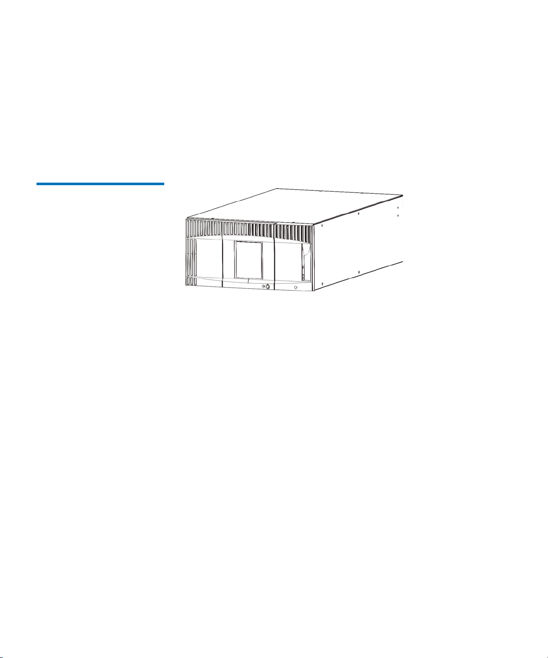
Figure 1 5U Library
1
Configuration (Standalone
Control Module)
Chapter 1 Description
Library Configuration
The 5U, 14U, and 23U libraries are the base Scalar i500 systems. By
adding 9U expansion modules, you can upgrade a base system to:
• A 32U library, consisting of one 5U control module and three 9U
expansion modules
• A 41U library, consisting of one 5U control module and four 9U
expansion modules
Scalar i500 User’s Guide 12
Page 29
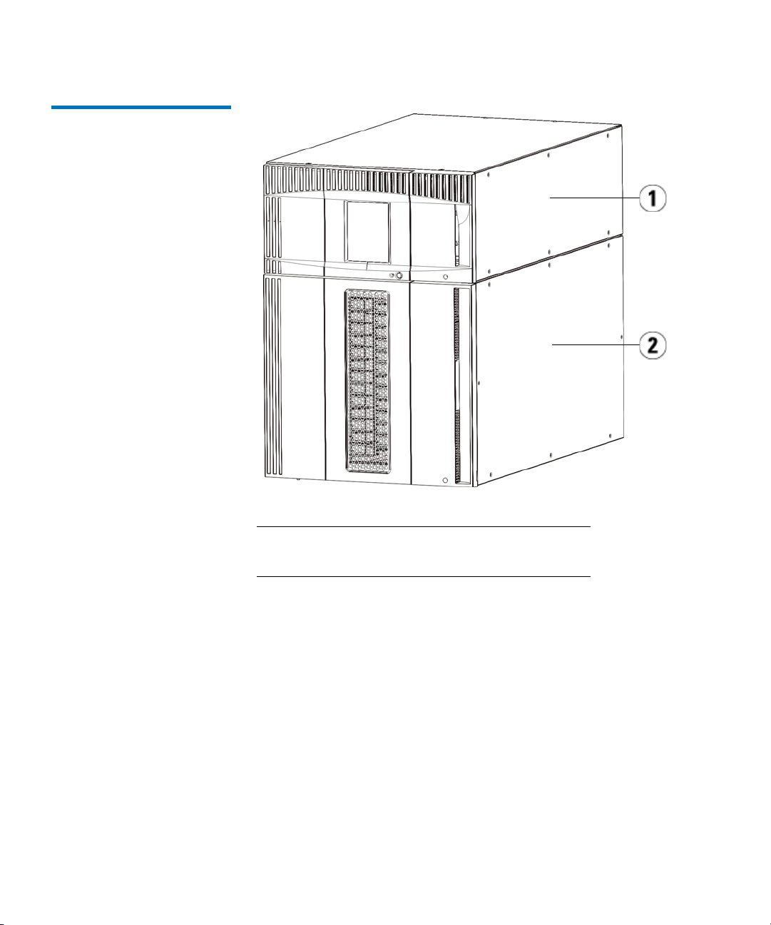
Figure 2 14U Library
Configuration (5U Control
Module Plus One 9U
Expansion Module)
Chapter 1 Description
Library Configuration
1 Control module
2 Expansion module
Scalar i500 User’s Guide 13
Page 30

Figure 3 23U Library
Configuration (5U Control
Module Plus Two 9U Expansion
Modules)
Chapter 1 Description
Library Configuration
1 5U control module
2 9U expansion module
3 9U expansion module
Scalar i500 User’s Guide 14
Page 31

Modules
Chapter 1 Description
Modules
Warning: All libraries taller than 14U must be installed in a rack
having a main protective earthing (grounding) terminal,
and power must be supplied via an industrial plug and
socket-outlet and/or an appliance coupler complying with
IEC 60309 (or an equivalent national standard) and having
a protective earth (ground) conductor with a crosssectional area of at least 1.5 mm2 (14 AWG).
To ensure proper airflow and access space, allow 60 cm (24
inches) in the front and back of the library.
Scalar i500 libraries are modular, and you can increase the size at any
time. The three base systems for the Scalar i500 library are as follows:
• The 5U library, consisting of a control module
• The 14U library, consisting of a 5U control module and a 9U
expansion module
• The 23U library, consisting of a 5U control module and two 9U
expansion modules
These configurations can be scaled up by adding 9U expansion modules
to a maximum rack height of 41U. Expansion modules provide additional
capacity as your storage and tape drive requirements change. See Figure
4 on page 17 for an illustration of library scalability. For information on
installing, removing, and replacing modules, see Installing, Removing,
and Replacing on page 211.
Each module has a specific number of fixed storage slots, I/E station
slots, and tape drive slots available. See Library capacity is as follows.
page 407 for the number of slots available for each library configurations.
Note: Slot counts in this document do not include five inaccessible
slots in the bottom row of any library configuration. For more
information about these slots, see Unused Slots
Scalar i500 User’s Guide 15
on page 175.
on
Page 32

Chapter 1 Description
Modules
Control Module 1
Expansion Modules 1
Stackability 1
The control module is required in any Scalar i500 library configuration.
The control module contains the robotic controls, library control blade
(LCB), and touch screen display. The control module also contains an
import/export (I/E) station, fixed storage slots, tape drives, and at least
one power supply.
Expansion modules are supplementary modules that can be stacked
above or below the control module. Each expansion module contains
fixed storage slots, tape drive slots, and power supply slots.The I/E
stations on expansion modules are included and may be configured as
storage. Expansion modules also contain bays for optional Fibre Channel
(FC) Input/Output (I/O) blades, which provide FC connections for FC
drives in the library.
If an expansion module is used only for storage and does not contain tape
drives or FC I/O blades, it does not need a separate power supply. All
power is derived from the control module.
The maximum rack height of the library is 41U, which consists of a 5U
control module and four 9U expansion modules. Figure 4
illustrates the
stackability of the library and the recommended library configurations.
Scalar i500 User’s Guide 16
Page 33

Figure 4 Base Systems Plus
Expansion Modules
Chapter 1 Description
Modules
5U
(41 slots)
5U Control
Module
14U
(133 slots)
5U Control
Module
9U Expansion
Module
23U
(225 slots)
5U Control
Module
9U Expansion
Module
9U Expansion
Module
32U
(317 slots)
5U Control
Module
9U Expansion
Module
9U Expansion
Module
9U Expansion
Module
41U
(409 slots)
9U Expansion
Module
5U Control
Module
9U Expansion
Module
9U Expansion
Module
9U Expansion
Module
Scalar i500 User’s Guide 17
Page 34

Front Panel Components
Figure 5 shows the front panel components of the library. The paragraphs
following Figure 5
Figure 5 Front Panel
Components
Chapter 1 Description
Front Panel Components
describe the components in detail.
1 Access door
2 Operator panel
3 I/E station
4 Front power button
Access Door 1
Scalar i500 User’s Guide 18
The access door allows access to the internal components of the library.
Each control module and expansion module has an access door. In most
Page 35

Chapter 1 Description
Front Panel Components
cases, you will not need to access the library through this door except
when you want to bulk load or unload cartridges from the library.
The access door is locked by the I/E station door. To open the access
door, you must first open the I/E station door. If you want to prohibit
access to the library, which is recommended for security reasons, lock the
I/E station door. This keeps unauthorized users from accessing tape
cartridges.
You can lock and unlock the I/E station door using commands on the
Operations menu. For more information, see Locking and Unlocking the
I/E Stations on page 188.
If the access door is opened, the library is not available for use. When an
access door (on any module) is opened, all in-progress motion commands
are stopped, and the picker slowly lowers to the bottom of the library.
When the access door is closed, the library returns any media in the
picker to its original slot and also performs a library inventory.
Caution: Care should be taken to avoid opening the access door
during robotic operations since the robot will stop
immediately and will fail to complete the current
operation.
I/E Station 1
I/E stations enable importing and exporting cartridges with minimal
interruption of normal library operations. I/E stations are located on the
front of the control module and on the front of expansion modules. A 5U
I/E station has a capacity of six cartridges within a removable magazine.
A 9U I/E station has a capacity of 12 cartridges within two removable
magazines.
The I/E stations can also be configured as storage as well as become part
of a logical division of library resources known as a partition. The I/E
station is shared among all partitions, but the I/E station slots are owned
by one partition at a time. When an I/E station slot is assigned to a
partition, only the assigned partition can access that slot.
Operator Panel 1
The operator panel is the touch screen display device upon which the
graphical user interface (GUI) appears. The operator panel is located on
the access door of the control module. The library operations and service
functions are performed from this screen. The GUI is also accessible
Scalar i500 User’s Guide 19
Page 36

Chapter 1 Description
Back Panel Components
through a remote web client. For more information on the library user
interfaces, see Chapter 2,
Understanding the User Interface.
Front Power Button 1
Turning off the front power button turns off the robot and operator panel,
but power still runs to the power supplies. Use the front power button to
manually shut down the library. See Shutting Down or Restarting the
Library on page 190 for instructions on how to shut down or restart the
library safely.
Back Panel Components
Figure 6 shows the back panel components of the library. The paragraphs
following Figure 6
describe the components in detail.
Scalar i500 User’s Guide 20
Page 37

Figure 6 Back Panel
Components
Chapter 1 Description
Back Panel Components
1 Library control blade (LCB)
2 FC I/O blade (optional)
3 FC I/O fan blades (required with FC I/O blades)
4 Rear power switch
5 Power supplies
6 Upper and lower Ethernet ports on expansion
module
7 Module terminator connectors
Scalar i500 User’s Guide 21
Page 38

Chapter 1 Description
Back Panel Components
Rear Power Switches 1
Power System 1
Rear power switches are located on each power supply. Turning off the
rear power switch on a power supply removes all power from the library.
The rear power switches should be used in all emergency and service
situations.
Warning: Turn off the rear power switch whenever you are servicing
the library. In the event of danger to personnel or
property, immediately turn off the rear power switch and
remove all power cords.
Caution: Except in emergencies, use the shutdown procedure
before switching off the rear power switch. See Shutting
Down or Restarting the Library on page 190 for
instructions on how to shut down the library.
The library supports single and redundant power configurations. The
single power configuration has a single AC line input and single DC
power supply. The redundant configuration has dual AC line input and
dual DC power supplies.
If you have redundant power supplies, you can “hot swap” a power
supply (power to the library remains on while you exchange the
hardware), and you can “hot add” power supplies to other modules
(power to the library remains on while you are adding the hardware).
Caution: At least one power supply must be plugged in at all times.
Warning: The power outlet must be available near the library and
must be easily accessible.
Caution: The control module and each expansion module that
contains drives must have at least one power supply for
every four drives. You can add a redundant power supply
to each module. Installing one power supply in one
module and another power supply in another module
does not provide redundant power; the two power
supplies must reside in the same module.
Scalar i500 User’s Guide 22
Page 39

Chapter 1 Description
Back Panel Components
The power system consists of the following components:
• Power supply
• AC power cord
The power supply has three light-emitting diodes (LEDs) that provide
status information. These LED status indicators are green and blue in
color.
•
Green represents AC OK or DC OK.
•
Blue represents swap-mode power status.
Figure 7
shows the power supply LEDs. For more information on the
behavior of the LEDs, see Power Supply LEDs
on page 390.
Scalar i500 User’s Guide 23
Page 40

Figure 7 Power Supply LEDs
Chapter 1 Description
Back Panel Components
1LEDs
Library Control Blade 1
The library control blade (LCB) manages the entire library, including the
operator panel and picker assembly, and is responsible for running
system tests to ensure that the library is functioning properly. The LCB
also provides internal communication to Fibre Channel (FC) I/O blade
slots. The LCB has four Ethernet ports, supporting a total of four FC I/O
blades in the library.
The LCB indicates its status with three LED Reliability, Availability, and
Serviceability (RAS) status indicators. These indicators are green, amber,
and blue in color.
Scalar i500 User’s Guide 24
Page 41

• Green represents processor status.
•
Amber represents health status.
•
Blue represents power-control status.
Chapter 1 Description
Back Panel Components
Figure 8
shows the location of the LCB components, including LEDs. For
more information on the behavior of the LCB LEDs, see LCB
Blade LEDs on page 384.
and FC I/O
Scalar i500 User’s Guide 25
Page 42

Figure 8 Library Control Blade
Chapter 1 Description
Back Panel Components
1 LEDs (blue, amber, green)
2 Gigabit Ethernet (external network) port
3 Ethernet I/O blade control ports (inactive if FC I/O
blades are not installed)
4 Service Ethernet port
5 Service serial port
Fibre-Channel Input/Output Blades 1
Expansion modules support optional Fibre Channel (FC) Input/Output
(I/O) blades that provide connections for FC tape drives in the library.
Each FC I/O blade has an embedded controller that provides
connectivity and features that enhance the performance and reliability of
tape drive operations. I/O blades also aggregate FC tape drive
connections, reducing switch port and cabling requirements.
Scalar i500 User’s Guide 26
Page 43

Chapter 1 Description
Back Panel Components
Each FC I/O blade has six auto-negotiating, 4 Gb/s FC ports and
backplane connections. The FC I/O blade provides two host
communication ports and four connection ports to FC drives. Each FC
I/O blade is cooled by a fan blade that is installed next to the FC I/O
blade in the expansion module. FC I/O blades and fan blades are hotswappable.
FC I/O blades cannot be installed in the control module, so your library
configuration must include at least one expansion module to include FC
I/O blades. Each expansion module can house up to two FC I/O blades.
Depending on the number of installed expansion modules, the library can
support from one to four FC I/O blades. No library configuration can
contain more than four FC I/O blades. Any FC drive in the library,
including drives in the control module, can be connected to an FC I/O
blade in an expansion module.
Note: FC I/O menu commands are available for use only when FC
I/O blades are installed in the library.
The FC I/O blade indicates its status with three LED status indicators.
These indicators are green, amber, and blue in color.
Green represents processor status.
•
•
Amber represents health status.
•
Blue represents power-control status.
Figure 9
on the behavior of the FC I/O Blade LEDs, see LCB
shows the FC I/O Blade, including LEDs. For more information
and FC I/O Blade
LEDs on page 384.
For information on configuring I/O blades, see Working With FC I/O
Blades on page 100.
For information on installing and cabling FC I/O blades and FC tape
drives, see Chapter 11,
Scalar i500 User’s Guide 27
Installing, Removing, and Replacing.
Page 44

Figure 9 FC I/O Blade
Chapter 1 Description
Back Panel Components
1 FC ports to host(s)
2 FC ports to drive(s)
3 LEDs (blue, amber, green)
Each FC I/O blade is cooled by a fan blade that is installed next to the FC
I/O blade in the expansion module. For information on installing the fan
blade, see Adding, Removing, and Replacing the FC I/O Fan Blade
on
page 360.
Figure 10
shows the FC I/O fan blade, including the LED. The single
amber LED represents health status. For more information on the
behavior of the FC I/O fan blade LED, see FC I/O Fan Blade LED
on
page 387.
Scalar i500 User’s Guide 28
Page 45

Figure 10 FC I/O Fan Blade
Chapter 1 Description
Robotic System and Barcode Scanner
1 LED (amber)
Robotic System and Barcode Scanner
The robotic system identifies and moves the cartridges between the
storage slots, tape drives, and the I/E station. The robotic arm (picker)
has picker fingers that enable it to grab tape cartridges and move them
into positions along X, Y, and Z motion coordinates. The robotic system
and the barcode scanner work together to identify the locations of
resources within the library.
Each tape cartridge must contain a barcode that the barcode scanner
reads during the inventory process. During the inventory process, the
Scalar i500 User’s Guide 29
Page 46

barcode scanner reads the fiducial labels to identify the types of
magazines and tape drives that are installed in the library.
Every tape cartridge must have a unique machine-readable barcode
attached to it. Tape cartridges cannot have duplicate barcode labels. This
barcode identifies the cartridge. The library stores the physical location of
the tape cartridge in an inventory database. All library or host requests
typically reference the location of the tape cartridges based on this
barcode number. Barcode labels are mandatory and must adhere to
specific standards. For more information on barcodes, see Chapter 13,
Working With Cartridges and Barcodes.
Tape Drive Support
Details about tape drive support include:
Chapter 1 Description
Tape Drive Support
• Every library configuration must contain at least one tape drive.
• Control modules can hold a maximum of two tape drives.
• Expansion modules can hold a maximum of four tape drives.
Please see Supported Components
and media supported by the Scalar i500 library.
The library supports mixing different tape drive types within the library
and within partitions. For information on how to do this, see Working
With Partitions on page 62.
SCSI and SAS tape drives are attached directly to the host. FC tape drives
can be directly attached to hosts or to the Storage Area Network (SAN).
FC tape drives can also be attached to FC I/O blades, which manage
communication between the hosts and the drives. For more information
on FC I/O blades, see Working With FC I/O Blades
LTO-5 Fibre Channel tape drives can use the library’s Storage
Networking features (see Chapter 6,
Tape drives are installed into tape drive slots in the rear of the library. If a
tape drive slot is empty, a filler plate covers the empty tape drive slots to
prevent debris from entering the library. Tape drives are shipped filling
Scalar i500 User’s Guide 30
on page 405 for a list of tape drives
on page 100. HP
Storage Networking).
Page 47

Chapter 1 Description
Library Features
the tape drive slots from the bottom to the top of the library, but the tape
drives can be reinstalled in any available tape drive slot.
Note: Tape drive filler plates must be in place for the library to
operate at normal speed.
Library Features
User Interface 1
Partitions 1
For information on adding tape drives, see Adding a Tape Drive
page 346.
This section describes several features of Scalar i500 libraries.
The operator panel is located on the front door of the control module and
allows you to work locally on the library via the user interface. The web
client allows you to view and perform library functions from remote sites
and is accessible through a browser. The operator panel and web client
contain a similar user interface and functionality.
See Chapter 2,
about the operator panel and the web client.
Partitions are virtual sections within a library that present the appearance
of multiple, separate libraries for purposes of file management, access by
multiple users, or dedication to one or more host applications.
Understanding the User Interface for more information
on
Organizing the library into partitions divides the resources into virtual
sections. Partitions can be used to control access to portions of the library
by granting permissions to user accounts to access certain partitions.
For more information on partitions, see Working With
page 62.
Scalar i500 User’s Guide 31
Partitions on
Page 48

Chapter 1 Description
Licensable Features
Control Path Modification1
Support for WORM 1
The control path tape drive is used to connect a partition to a host
application. Only one tape drive can be selected as the control path at one
time. For more information, see Working With Control Paths
Scalar i500 tape libraries support WORM (write once, read many)
technology in LTO-3, LTO-4, and LTO-5 tape drives. WORM allows nonrewriteable and non-erasable data to be written and provides extra data
security by prohibiting accidental data erasure. The WORM feature is
supported whenever you use WORM cartridges.
Licensable Features
In addition to the standard features, the following additional, licensable
features are available for the Scalar i500:
• Advanced Reporting, described in Chapter 4,
• Capacity on Demand, described in Chapter 5, Capacity on Demand
• Storage Networking, described in Chapter 6, Storage Networking
on page 79.
Advanced Reporting
• Encryption Key Management, described in Chapter 7, Encryption
Key Management
If you purchase these features with your library, the license will be
installed when you receive the library. If you upgrade or add new
features after the initial purchase, you will need to obtain and install a
license key. For information on how to obtain and install a license key, see
Obtaining and Installing a License Key
Scalar i500 User’s Guide 32
on page 81.
Page 49

Chapter 2
2Understanding the User Interface
The user interface of Scalar i500 libraries is available in two formats: the
operator panel and the web client. Operations on the library can be
performed locally on the control module using the operator panel or
remotely on your computer using the web client. Similar functionality
with common elements is used for both formats.
Both the web client and operator panel user interfaces are required to
operate the library. Some functionality is only available through the web
client, and some functionality is only available through the operator
panel. However, using the web client rather than the operator panel to
perform library operations (when possible) is recommended.
Caution: Do not perform inventory operations (for example,
working with RAS tickets, creating/modifying/deleting
partitions) while the library is performing an inventory.
Doing so may result in inventory discrepancies, such as
missing tape cartridges.
This chapter covers:
• Common User Interface Elements
• Operator Panel
• Web Client
• Menu Trees
Scalar i500 User’s Guide 33
Page 50

• User Privileges
• User Access
Common User Interface Elements
The user interface consists of the following areas:
•
Header — appears on every screen and contains the company logo,
product name, and the three main navigation buttons. The main
navigation buttons are:
Home — Home page.
•
•
Help — Context-sensitive Help for the active screen.
•
Logout — Ability to log out.
• Title Bar/Menu Tabs (operator panel)— This area appears below the
header. On the home page, it provides the library/partition name
and access to the menu tabs on the main screen. On all other screens,
this area is a single bar and provides the screen name.
•
Menu Bar (web client)— Lists the menu choices.
Chapter 2 Understanding the User Interface
Common User Interface Elements
•
Main — Main content area of the screen.
•
Health/Navigation — provides information about the “health” of the
library by means of three subsystem status buttons:
Media. See System Summary and Subsystem Status on page 36
and
Library, Drives,
for more information on the subsystem buttons.
Note: A message in the header alerts you when the robot is not ready
to perform library functions. See Troubleshooting “Library
Not Ready” Messages on page 375 for more information on
“Library Not Ready” messages displayed in the header.
Figure 11
and Figure 12 show the operator panel and the web client
interfaces.
Scalar i500 User’s Guide 34
Page 51

Figure 11 Operator Panel User
Interface
Chapter 2 Understanding the User Interface
Common User Interface Elements
Figure 12 Web Client User
Interface
Scalar i500 User’s Guide 35
Page 52

Chapter 2 Understanding the User Interface
Common User Interface Elements
System Summary and Subsystem Status 2
You can quickly gauge the health of the library by observing the color of
the three subsystem status buttons located at the bottom of the home
page. These buttons provide quick access to information about the
“health” of the library for faster recovery if problems occur. You can
select the buttons to view Reliability, Availability, and Serviceability
(RAS) tickets that report problems in the subsystems.
The three subsystems are:
Library — This subsystem represents connectivity, control, cooling,
•
power, and robotics.
•
Drives — This subsystem represents tape drive components, such as
tape drives, tape drive firmware, and tape drive sleds.
•
Media — This subsystem represents media components, such as
cartridges and barcode labels.
Each subsystem button will be in one of three states indicated by color.
The three states are:
•
Green — No RAS tickets exist for this subsystem, or, if any tickets do
exist, they have all been closed.
•
Yellow — The library contains open or unopened, low- or high-
priority RAS tickets for this subsystem.
•
Red — The library contains open or unopened urgent RAS tickets for
this subsystem.
If the color of a subsystem button is red or yellow, you can click the
button to display the corresponding
RAS Tickets screen. This screen lists
library, drives, or media RAS tickets, depending on which button was
selected. RAS tickets display in order of last occurrence of each event,
starting with the most recent.
Note:
Last Occurrence indicates the last time a ticket event occurred.
This information updates any time the event recurs.
Occurrence
does NOT update if you open, close, or resolve the
Last
RAS Ticket.
You can change the order in which the RAS tickets are displayed by
clicking any header item (for example, Priority, Last Occurrence, or
Name).
Scalar i500 User’s Guide 36
Page 53

Chapter 2 Understanding the User Interface
Common User Interface Elements
On the web client, you can view closed tickets by selecting the Include
Closed Tickets
checkbox.
Home Page 2
You can also open the
Tickets
. See About RAS Tickets on page 367 for more information about
All RAS Tickets screen by selecting Tools > All RAS
RAS tickets.
The home page is common to both the operator panel and the web client.
The web client home page provides two modes of navigation to access
the user interface screens: tabs on the
function links on the
displays only the library
Library View. The home page on the operator panel
Capacity View.
Capacity View and categorized
Capacity View
The Capacity View screen is the default view of the library and provides
tabular data on the capacity of the library’s partitions, slots, and drives.
You can use the Capacity View to see a quick summary of the capacity of
the library. You can also see which partitions are online (in the Storage
Slots section). The current user’s login privileges determine the
information that is displayed in the Capacity View.
Details about Capacity View include:
• On the web client, users see the partitions (in alphabetical order) to
which they have access.
2
• On the operator panel, if users have access to more than one partition,
they can navigate to other partitions using the arrows next to the
partition name in the title bar at the top of the screen.
For more information about user privileges, see User Privileges
on
page 45 and .
On the web client, users can toggle between the
Library View.
Capacity View and the
Library View
Selecting the Library View button on the web client displays the Library
View. The Library View provides a graphical representation of the library
as well as another mode of navigation. Use the Library View to navigate
through the library. The control module is labeled with “hot” areas that
Scalar i500 User’s Guide 37
2
Page 54

Operator Panel
Chapter 2 Understanding the User Interface
Operator Panel
can be selected to access the functions for each area of the library. The
Library View represents the actual configuration of the user’s library,
including the order in which the modules are stacked. You will find the
same navigation buttons on the Library View as on the Capacity View.
The operator panel is physically attached to the front door of the control
module. The user interface appears on the touch-screen LCD display of
the operator panel for executing basic library management functions.
Audible feedback, or “key click” sounds, are generated when a user
presses a button on the operator panel. Users can choose to disable the
audible feedback. See Configuring System Settings
on page 116.
Operator Panel Keypads 2
Operator Panel Indicates Intervention Required 2
Web Client
When a user touches a text box requiring data entry, a keypad screen
appears. The alpha, numeric, or month keypad appears, depending on
the type of input field touched. All alphabetic character entries are lower
case. The text box appears at the top of screen, and the
numbers/characters appear as they are entered. Pressing
numeric keypad.
The operator panel lights up (screen saver turns off) if intervention is
required. For example, the operator panel lights up following an import
of tapes into the I/E station so that the operator sees the prompt to assign
tapes to a partition.
The web client user interface is similar to the operator panel user
interface. The web client interface is accessible from supported web
123 opens the
Scalar i500 User’s Guide 38
Page 55

Chapter 2 Understanding the User Interface
Menu Trees
browsers. See System Requirements on page 406 for information about
supported browsers.
To manage the library from a remote location, you must set up the
library’s initial network configuration from the operator panel touch
screen. See Configuring Library Security Settings
information on setting the network configuration settings for remote use.
You must disable web browser popup blockers to use the web client
interface and the library’s online Help. Add the Scalar i500’s Internet
Protocol (IP) address to the list of trusted/allowed sites on your Scalar
i500-supported browser, so the web client pages will automatically
refresh.
on page 115 for
Menu Trees
Note: Do not use your Internet browser
web client pages. Instead, use the buttons provided within the
web client.
Note: Log out of the library before closing the Internet browser
window when you are using the web client. If you do not log
out, the session will remain open.
The following menus organize operations and commands into logical
groupings:
•The
•The
Setup menu consists of commands that administrators can use to
set up and configure various aspects of the library, including
partitions, I/E station slots, cleaning slots, control paths, network
settings, drive settings, users, notifications, date and time, licenses,
FC I/O blades, library registration, and e-mail.
Operations menu consists of commands that enable users to
change the library’s mode of operations, import and export
cartridges, load and unload tape drives, move media, perform
diagnostics, and log off. Administrators can also access commands to
lock or unlock the I/E station and to shut the library down.
Back button to navigate the
Scalar i500 User’s Guide 39
Page 56

Chapter 2 Understanding the User Interface
Menu Trees
•The Tools menu consists of commands that you can use to maintain
your library, such as viewing RAS Tickets, generating diagnostic
logs, identifying drives, configuring the internal network, saving and
restoring the library configuration, setting system and security
settings, and updating firmware.
•The
Reports menu (web client only) consists of summaries of library
information.
A hidden
Service menu is available to service users with the appropriate
login information.
The menus vary somewhat between the web client and operator panel
user interfaces. Administrators have access to all menu commands; users
with user privileges have more limited access.
Table 1
lists the web client menus. Some menu commands are available
only to administrators.
I/O blade menu items are available for libraries that contain I/O blades.
Scalar i500 User’s Guide 40
Page 57

Table 1 Web Client Menus
Chapter 2 Understanding the User Interface
Menu Trees
Setup Menu
•Setup Wizard
•Partitions
• Host Access
• Host Registration
• Host Connections
• Cleaning Slots
• I/E Station Slots
•Drive Settings
• Control Path
•License
• Notifications
• E-mail Configuration
• Advanced Reporting
(if licensed)
• Receiver
• Media Security
•RAS
• Receiver
• Contact
• Network Management
•Network
•SNMP
•SNMP Trap
Registrations
*
Addresses
Addresses
Information
Operations Menu Tools Menu
•Media
•Move
•Import
• Export
• Cleaning Media
•Import
• Export
• Partitions
• Change Mode
•Drive
• Load
• Unload
• Change Mode
• I/E Station
Lock/Unlock*
• System Shutdown*
• Logout
• All RAS Tickets
• Capture Snapshot
• Save/Restore
Configuration
•E-mail
Configuration
Record
• Save Configuration
Record
• Identify Drives
• Drive Operations
• Download SNMP
MIB
• IO Blade Info**
• IO Blade Port Info**
• EKM Management
•Import
Communication
Certificates
• Encryption
Certificate
•Import
• Export
• Encryption Key
•Import
• Export
• Retrieve SKM Logs
(if SKM enabled)
*
Reports Menu
• System Information
• Library Configuration
• Network Settings
• Logged In Users*
• All Slots
• Log Viewer*
• Advanced Reporting*
• Drive Resource
Utilization
• Media Integrity
Analysis
• About
Scalar i500 User’s Guide 41
Page 58

Chapter 2 Understanding the User Interface
Menu Trees
Setup Menu
• User Management
• User Accounts
• Remote
Authentication
• IO Blades**
• Port Configuration
• Channel Zoning
• Host Mapping
• Host Management
• Host Port Failover
•Data Path
Conditioning
• I/O Blade Control
• Encryption (if licensed)
• System Configuration
• Partition
Configuration
• System Settings
• Date & Time
• Register Library
*
Operations Menu Tools Menu
• Update Library
Firmware
• Diagnostics
*
Reports Menu
*
Administrators only. **Available only when the library contains I/O blades.
Table 2 lists the operator panel menus. Some menu commands are
available only to administrators. I/O blade menu items are available for
libraries that contain I/O blades.
Scalar i500 User’s Guide 42
Page 59

Table 2 Operator Panel Menus
Setup Menu
a
Chapter 2 Understanding the User Interface
Menu Trees
Operations Menu Tools Menu
• Partition Mgmt
• Create Partition
• Delete Partition
• Configure I/E Station Slots
• Configure Cleaning Slots
• User Mgmt
• Create User
• Modify User
•Drive Settings
•Fibre
•SCSI
• SAS
• Notification
• E-mail Alerts
• E-mail Account
• Customer Contact
•Licenses
• Date & Time
• Network Mgmt
• IP version 4
• IP version 6 (if enabled)
• Port Settings
• Control Path
• Move Media
• Import Media
• Export Media
• Import Cleaning Media
• Export Cleaning Media
• Change Partition Mode
•Load Drive
• Unload Drive
• Change Drive Mode
• Lock/Unlock I/E Station
• Shutdown
a
• All RAS Tickets
a
• Capture Snapshot
• Drive Mgmt
a
• Clean drive
• Reset drives
•Drive Info
• About Library
• Network Info
• View Drive Info
a
• Partition Info
• Internal Network
a
• System Settings
• User Session Timeout (minutes)
• Touch Screen Audio
• Unload Assist
• Logical SN Addressing
• Manual Cartridge Assignment
• Disable Remote Service User
• Enable SSL
• Enable SNMP V1/V2
• Enable IPv6
• Enable SMI-S
• Unlabeled Media Detection
a
a
a
a
a
a
Scalar i500 User’s Guide 43
Page 60

Chapter 2 Understanding the User Interface
Menu Trees
Setup Menu
• IO Blades
a
b
• Port Configuration
• Channel Zoning
• Host Mapping
c
• Host Management
• Host Port Failover
• Data Path Conditioning
• Blade Control
Operations Menu Tools Menu
Security
c
Display Settings
• Library Tests
• Blade Info
• Command History Log
a
• Network Interf ace
• SSH Services
•ICMP
• Remote UI
•SNMP
•SMI-S
• Brightness
• Contrast
• Defaults
a
• Installation & Verification Test s
• Library Demo
• View Last Summary Log
• View Last Detailed Log
• E-mail Last Detailed Log
b
• Port Info
ab
a
Administrators only. bAvailable only when the library contains I/O blades. cVisible only when host mapping has
been enabled.
Scalar i500 User’s Guide 44
Page 61

User Privileges
Chapter 2 Understanding the User Interface
User Privileges
User privilege levels are manually assigned to user accounts created
within the library. Controlling access to screens and operations within the
library preserves the integrity of the library and the data that is stored in
it. See Working With User Accounts
on page 89 for more information on
setting user privilege levels.
Three types of users are defined in Scalar i500 libraries:
•
Administrators have access to the entire physical library and all of its
partitions, and can configure the library and set up user and
administrator accounts. The library ships with a default
administrator account. The user name for the default administrator
account is
admin and the password is password. You cannot modify
or delete the user name for the default administrator account, but you
can modify the password. If you misplace the password for the
default administrator account, contact Quantum Technical Support
(see Getting More Information or Help
on page 8).
•
Users have access to one or more assigned partitions, as well as
portions of the
Setup and Tools menus. Users can perform functions within a
the
Operations and Reports menus. Users cannot access
partition (such as performing cartridge and tape drive operations),
but cannot set up or configure the library (for example, creating or
deleting partitions).
Service has access to the entire physical library and all of its partitions
•
as well as to a hidden
Service menu that includes service and
diagnostic tools. Each library has only one service account.
Details on user privileges include:
• The library can contain eighteen user accounts (user or administrator
or both), including the default administrator account.
• Eighteen user (user or administrator or both) sessions can be active at
one time.
• The same user can be logged in to a library from multiple remote
locations.
• Clicking the close button (
X) in the upper-right corner of the web
client closes the browser window but does not log the user or
administrator out.
Scalar i500 User’s Guide 45
Page 62

Chapter 2 Understanding the User Interface
User Access
• All users are logged out automatically after a configurable period of
inactivity. The default user session timeout period is 30 minutes, but
administrators can change the user session timeout to a value from 15
minutes to 480 minutes (eight hours). See Configuring System
Settings on page 116.
• A screen saver is invoked after 10 minutes of inactivity on the
operator panel. After an hour of inactivity, the screen will appear
black. If the user has not been logged out for inactivity, touching the
operator panel will reactivate it, returning the user to the screen last
in use. (The web client does not use a screen saver.)
• An administrator can disable any access to the library from the web
client. For more information, see Configuring System Settings
page 116.
• When a service user logs in, all other active users are automatically
logged out.
• For security purposes, an administrator can prevent a service user
from logging on to the library remotely, from either the web client or
over the Ethernet service port. The service user will still be able to log
on to the library from the operator panel interface. For more
information, see Configuring System Settings
on page 116.
on
User Access
Administrators have access to the entire library. Users with user
privileges can only access some of the menus. See Table 1 on page 41
the web client menu tree and privilege level information. See Table 2 on
page 43 for the operator panel menu tree and privilege level information.
Scalar i500 User’s Guide 46
for
Page 63

Chapter 3
3Configuring Your Library
Once you have installed the hardware as described in the Scalar i500
Getting Started Guide, you are ready to configure your library’s settings. A
Setup Wizard helps you get started configuring your library, and menu
commands on both the operator panel and the web client allow you to
reconfigure your library at any time.
Caution: Always save the library configuration after modifying
configurable items. This will allow you to restore the most
current settings if necessary. See Saving and Restoring the
Library Configuration on page 373.
This chapter covers:
• About the Setup Wizard
• Using the Setup Wizard
• Logging On to the Web Client
• Managing the Network
• Working With Partitions
• Configuring Cleaning Slots
• Configuring I/E Station Slots
• Setting Tape Drive Parameters
• Working With Control Paths
Scalar i500 User’s Guide 47
Page 64

Chapter 3 Configuring Your Library
• Obtaining and Installing a License Key
• Setting Customer Contact Information
• Configuring the Library E-mail Account
• Working With RAS E-mail Notifications
• Working With User Accounts
• Setting the Date, Time, and Time Zone
• Working With FC I/O Blades
• Configuring Library Security Settings
• Configuring the Internal Network
• Configuring System Settings
• Configuring Operator Panel Display Settings
• Registering the Library
About the Setup Wizard
About the Setup Wizard
When you first power on the library, the operator panel displays the
Setup Wizard, which walks you through the initial configuration of the
library’s basic operational settings.
The Setup Wizard on the operator panel only runs once, at initial startup.
After that, administrators access the Setup Wizard any time via the web
client or use commands on the
library settings, including network settings. See Completing the Library
Configuration With Menu Commands on page 49.
While completing the Setup Wizard at initial startup is recommended,
you may need to begin using the library locally immediately. In this case,
you can cancel out of the Setup Wizard and allow the library to run on the
default configuration settings. See Default Configuration Settings
page 52.
For additional information, see Using the Setup Wizard
Scalar i500 User’s Guide 48
Setup and Operations menus to modify all
on
on page 50.
Page 65

Chapter 3 Configuring Your Library
About the Setup Wizard
Using the Default Administrator Account 3
Completing the Library Configuration With Menu Commands 3
When you power on the library for the first time, you do not need to log
in to use the operator panel. You can start using the
Setup Wizard
immediately. After the initial setup session on the operator panel,
however, you will need to log in to the operator panel as well as the web
client.
The library ships with a default administrator account. The user name on
the account is
Login screen on the operator panel or web client, type admin in the User
Name
text box and password in the Password text box. As soon as the
admin and the password is password. When you see the
initial setup is complete, you should change the password on the default
administrator account. For information on changing passwords, see
Modifying Local User Accounts
on page 91.
Note: You cannot delete the default administrator account or modify
the user name. You can, however, change the password.
Note: If you misplace the password for the default administrator
account, contact Quantum Technical Support (see Getting
More Information or Help on page 8).
The Setup Wizard is an aid to assist you with the initial configuration of
the library. The Setup Wizard, however, contains only a subset of
configuration tasks. The operator panel tabs and web client menus
provide access to all configuration options that are included in the Setup
Wizard and many that are not. Once the initial Setup Wizard session is
complete, administrators can choose whichever method is most
convenient or necessary for modifying library settings.
The following topics cover using the Setup Wizard as well as Setup and
Operations commands to configure the library. Paths to open the
appropriate screens on both the operator panel and the web client are
given for each task. For the operator panel, the paths refer to the
navigation tabs at the top of the home page. For the web client, the paths
refer to the menus.
For the menu trees on both the operator panel and web client, see Menu
Trees on page 39.
Scalar i500 User’s Guide 49
Page 66

Note: Power cycling (powering the library on and off) is not
Using the Setup Wizard
The Setup Wizard simplifies the process of configuring the library. When
you first power on the library, the operator panel displays the Setup
Wizard. After that, you can no longer access the Setup Wizard from the
operator panel. You can always access the Setup Wizard from the
menu on the web client.
The recommended procedure for using the Setup Wizard for the initial
configuration is as follows:
1 Turn on the library and begin using the Setup Wizard on the operator
panel.
Chapter 3 Configuring Your Library
Using the Setup Wizard
necessary to configure the library.
Setup
2 Work through all of the screens as prompted (see Setup Wizard Tasks
on page 52).
3 When you get to the network configuration screens, configure the
network settings as follows:
Note: You cannot log into the web client until you have
configured the network settings.
• If you are using IPv4: On the Setup Wizard: Enable IPv6 screen, do
NOT select the
Enable IPv6 checkbox. Click Next. Configure the
network settings.
•
If you are using IPv6: On the Setup Wizard: Enable IPv6 screen,
select the
Enable IPv6 checkbox and click Next. You have enabled
IPv6 but you will not be prompted to configure IPv6 settings
here. Continue with the Setup Wizard screens. Then, when you
are finished using the Setup Wizard, configure the IPv6 network
settings by going to
Setup > Network Mgmt on the operator panel.
4 Log out of the operator panel.
Scalar i500 User’s Guide 50
Page 67

Chapter 3 Configuring Your Library
Using the Setup Wizard
5 Using the default administrator account, log in to the web client.
admin in the User Name text box and password in the Password
Type
text box.
6 Complete the
Setup Wizard screen will prompt you to apply your settings.
final
When you have completed the
Setup Wizard screens on the web client interface. The
Setup Wizard, the Library
Configuration report appears on the web client. The Library
Configuration report provides information on the library’s tape
drives, partitions, I/E stations, storage slots, cleaning slots, and
loaded media. See Viewing the Library Configuration
on page 195 for
more information on the Library Configuration report.
Note: Depending on the size of the library, there may be a slight
delay after you apply the settings in the Setup Wizard
while the Library Configuration report page loads.
Details on using the Setup Wizard include:
• The only time that you do not need to log in to the library is when the
Setup Wizard appears on the operator panel the first time the library
is powered on.
• After a timeout period of one hour, the Setup Wizard will close, and
you will be logged out of the library. Use the default administrator
account to log in to the operator panel.
• If you time out of the Setup Wizard or do not complete all the Setup
Wizard screens, the library will apply the default configuration
settings plus whatever modifications you made (see Default
Configuration Settings on page 52).
• You cannot log in to the library from the web client until you have
configured network settings on the operator panel. To change IPv4
settings and configure IPv6 settings, go to
• You can return to the
Setup Wizard from the web client.
Setup > Network Mgmt.
• Any administrators you create will also be able to use the Setup
Wizard from the web client as well as
Setup and Operations menu
commands to reconfigure the library.
• If necessary, you can cancel out of the
Setup Wizard on the operator
panel and begin using the library locally with the default settings in
place. If you accept the default network configuration settings, you
Scalar i500 User’s Guide 51
Page 68

Chapter 3 Configuring Your Library
Using the Setup Wizard
will not be able to access the library remotely from the web client.
You can, however, use
Setup > Network Mgmt on the operator panel at
any time to modify network settings. See Default Configuration
Settings on page 52 for more information.
Default Configuration Settings 3
Setup Wizard Tasks 3
The default configuration settings are as follows:
•
License keys: COD, 41 slots minimum. The total number depends
on number of pre-activated slots purchased.
•
Network settings: DHCP enabled, IPv6 disabled
•
Import/export (I/E) station slots: 6
•
Cleaning cartridge slots: 0
•
Partitions: By default, the library creates partitions and assigns
available library resources proportionately among the partitions,
grouping tape drives according to distinct combinations of tape
drive interface type (SCSI, FC, or SAS) and tape drive vendor. To
mix tape drive types/vendors within a partition, create partitions
manually. See Manually Creating
See also About the Setup Wizard
on page 48.
Partitions on page 65.
As you work through the Setup Wizard screens, follow the on-screen
instructions.
The
Setup Wizard screens contains only a subset of all configuration
options. The
options, including those in the
Setup and Operations menus contain most configuration
Setup Wizard. This section includes
detailed descriptions of the configuration tasks, including how and when
to access them through the
Setup and Operations menus.
• Welcome (operator panel) — Welcomes you to the
• Hardware Installation
(operator panel) — Reminds you to install tape
Setup Wizard.
drives and the Ethernet cable.
• S
etting the Date, Time, and Time Zone (operator panel and web
client) — Allows you to set the date and time on your library.
• Managing the Network
(operator panel) — Allows you to configure
your IPv4 network settings for remote access using the web client.
Allows you to enable IPv6 so that you can configure IPv6 network
settings later using
Scalar i500 User’s Guide 52
Setup > Network Mgmt.
Page 69

Chapter 3 Configuring Your Library
Using the Setup Wizard
• Applying a License Key (operator panel and web client) — Allows
you to enter keys for licensed features. For more information, see
Obtaining and Installing a License Key
• C
onfiguring Cleaning Slots (operator panel and web client) — Allows
on page 81.
you to configure dedicated cleaning slots. Configuring at least one
cleaning slot enables the AutoClean feature.
• Configuring
I/E Station Slots (operator panel and web client) —
Allows you to configure import/export (I/E) station slots.
• Working With
Partitions (operator panel and web client) — Allows
you to set the number of library partitions.
•
Confirm Settings (operator panel and web client) — Allows you to
confirm your library settings.
Caution: Always take a library snapshot and save the library
configuration after modifying configurable items. If
modifying items results in issues, the library snapshot will
help technical support personnel to troubleshoot the
problem. Saving the library configuration will allow you
to restore the most current settings if necessary. For more
information on taking a library snapshot and saving and
restoring the library configuration, see Saving and
Restoring the Library Configuration on page 373.
Note: Setup Wizard operations cannot be performed concurrently by
multiple administrators logged in from different locations.
You can access the screens, but you cannot apply changes
while another administrator is performing the same operation.
The paths to open the appropriate screens are as follows:
• From the web client, select
• From the operator panel, the
Setup > Setup Wizard.
Setup Wizard is available only upon first
power-on of library.
Scalar i500 User’s Guide 53
Page 70

Logging On to the Web Client
Once you have configured network settings on the operator panel, you
can log on to the library’s web client.
The operator panel network configuration screen lists the IP address of
the library. Use this IP address to access the web client using a Web
browser. When typing the IP address into the Web browser, make sure to
precede it with http://; for example, http://123.123.123.123.
Managing the Network
Administrators can configure the following:
Chapter 3 Configuring Your Library
Logging On to the Web Client
Modifying Network
Settings 3
• Network settings that allow remote access to the library. For more information, see Modifying Network Settings
• Secure Socket Layer (SSL) settings that increase data protection so
that data from the library can be sent over the internet securely. For
more information, see Enabling SSL
• Simple Network Management Protocol (SNMP) settings that allow
you to use an external management application to monitor the status
of the library. For more information, see Configuring SNMP Settings
on the Library on page 58.
Caution: Security settings must be enabled to allow SNMP, SMI-S,
and IP address access to the library network. These
security settings are enabled by default. For more
information, see Configuring Library Security Settings
page 115.
The operator panel Setup Wizard allows administrators to configure
network settings that allow remote access to the library from the web
client. You must initially configure network settings from the operator
on page 57.
on page 54.
on
Scalar i500 User’s Guide 54
Page 71

Chapter 3 Configuring Your Library
Managing the Network
panel. After the initial configuration, you can modify the network
settings from either the operator panel or the web client.
From the operator panel, you can modify the following network settings:
library name, stateless configuration enable/disable (IPv6 only), static IP
configuration enable/disable (IPv6 only), DHCP enable/disable, IP
address, subnet mask, network prefix, and default gateway.
From the web client, you can use the
Setup - Network screen to modify the
following network settings: library name; Dynamic Host Configuration
Protocol (DHCP) enable/disable; stateless autoconfiguration
enable/disable (IPv6 only); static IP enable/disable (IPv6 only), IP
address; subnet mask (IPv4 only); net prefix (IPv6 only); and default
gateway address.
In addition, from the web client, when DHCP is disabled, can configure
the primary and secondary Domain Name System (DNS) server
addresses. DNS servers provide IP address resolution of fully qualified
domain names. DNS settings are optional.
If you modify the IP address, you will need to type the new IP address in
Address field of your Web browser to access the web client.
the
Note: Make sure that the library is connected to the network before
modifying network settings. If the Ethernet cable is not
installed properly, you cannot configure the network settings.
Install one end of the Ethernet cable in the top Ethernet port of
the library control blade (LCB) just below the three LEDs. The
LCB is located at the back of the control module. Make sure
the other end of the Ethernet cable is installed in the
appropriate LAN port on your LAN.
Details on network settings include:
•
Library Name is the network name you want to assign to the library.
The library name is limited to 12 lowercase alphanumeric characters
and dashes (-).
DHCP defaults to enabled. When DHCP is enabled, the library obtains
•
an IP address automatically. If DHCP is not enabled, you must
manually enter an IP address, default gateway, and subnet mask/net
prefix.
IPv4 addresses must be entered in dot notation (for example,
•
192.168.0.1). They are limited to numeric characters and do not allow
values exceeding 255 for dot-separated values.
Scalar i500 User’s Guide 55
Page 72

Chapter 3 Configuring Your Library
Managing the Network
• IPv6 addresses must be entered in the proper notation. IPv6 address
can be entered in the most common notation, as eight groups of four
hexadecimal digits. 2001:0ff8:55cc:033b:1319:8a2e:01de:1374 is an
example of a valid IPv6 address. Also, if one or more of the four-digit
groups contains 0000, you can omit the zeros and replace them with
two colons (::), as long as there is only one double colon used in an
address. Using this notation, 2001:0ff8:0000:0000:0000:0000:01de:1374
is the same as 2001:0ff8::01de:1374.
IP Address is the IP address of the library. For IPv4, this text box is
•
available only if DHCP is disabled.
•
Default Gateway Address is the IP address of the default gateway for
your portion of the Ethernet network. For IPv4, this text box is
available only if DHCP is disabled.
Subnet Mask (IPv4 only). Text box is available only if DHCP is
•
disabled.
•
Network Prefix (IPv6 only).
•
Primary DNS Address (optional, web client only) must be entered as
an IP address. This text box is available only if DHCP is disabled.
•
Secondary DNS Address (optional, web client only) must be entered
as an IP address. This text box is available only if DHCP is disabled.
•
Port Settings (operator panel only) allows you to change the
autonegotiate mode, speed, and duplex settings on the Ethernet port.
Caution: Modifying network settings will modify network
connectivity parameters, requiring remote communication
configuration changes. Your current web client browser
session might become invalid, requiring you to close your
current browser session. Access the web client using the
new network configuration settings and log in again.
Note: Be sure to add your library’s IP address to the list of
trusted/allowed sites on your library-supported browser, so
the web client pages automatically refresh.
Scalar i500 User’s Guide 56
Page 73

Chapter 3 Configuring Your Library
Managing the Network
Note: For step-by-step network configuration instructions, see your
library’s online Help. To access the online Help system, click
Help icon at the top right of the web client or operator
the
panel user interface.
The paths to open the appropriate screens are as follows:
Enabling SSL 3
• From the web client, select
• From the operator panel, select
Setup > Network Management > Network.
Setup > Network Mgmt.
Administrators can enable or disable SSL settings on the library. Enabling
SSL settings encrypts all web browser connections to the web client, and
it enables SSL-based authentication for SMI-S. SMI-S is the newest
standard of SNMP, which makes sets of data continuously available.
SMI-S is disabled by default. You can enable SMI-S on the
Settings
The default SSL setting is
screen on the operator panel.
Disabled. Disabling SSL settings creates an
To ols > System
unencrypted connection from a Web browser to the web client.
See the Scalar Intelligent Libraries SMI-S Reference Guide (6-01317-xx) for
further configuration and access details.
Note: Before enabling SSL settings, make sure you enter a name for
the library in the Library Name text box when configuring
network settings (
Setup > Network Mgmt on the operator
panel). After enabling SSL settings, use that library name to
access the library. If you do not use that name, you will receive
a security alert. In addition, make sure to complete all the text
boxes listed on the web client
Setup > Notification > Contact Information) before enabling SSL
(
Contact Information screen
settings. This information is used to identify company
information in the SSL certificate.
You cannot enable the SSL settings from the web client. The path to open
the appropriate screen is as follows:
• From the operator panel, select
Scalar i500 User’s Guide 57
Tools > System Settings > Enable SSL.
Page 74

Chapter 3 Configuring Your Library
Managing the Network
Configuring SNMP Settings on the Library 3
SNMP is a light-weight protocol designed for remote management and
monitoring of infrastructure devices. The library provides SNMP
support, so an external management application can be configured to
receive library SNMP information. The library supports SNMP by
publishing a Management Information Base (MIB) that can be queried to
obtain the status of the library and many of its individual components.
SNMP information can be obtained from the library using SNMP Traps
and GET queries.
For more information about SNMP, see the Scalar i500 Basic SNMP
Reference Guide (6-01370-xx). For information on integrating MIBs with an
SNMP management application, contact your network management
application vendor.
Administrators can perform the following SNMP procedures:
• Register the IP addresses and port numbers of external management
applications, enabling them to receive SNMP traps from the library.
For more information, see Registering External Management
Applications on page 58.
• Enable or disable support for SNMP v1 and v2c. SNMP v3 is enabled
by default and cannot be disabled. For more information, see
nabling SNMP Versions on page 60.
E
• Choose which version of SNMP the library uses to report traps. You
can choose SNMPv1 or SNMPv2. The default is SNMPv1.
• Modify the default SNMP community string, which is used as a
password to authenticate GET and GET-NEXT SNMP v1 and SNMP
v2c messages exchanged between the library and a remote
management application. For more information, see Modifying the
SNMP Community String on page 61.
• Enable or disable SNMP authentication traps, which are messages
indicating an authentication failure. For more information, see
Enabling and Disabling SNMP Authentication Traps
on page 61.
• Download the library MIB, which can be used to integrate the library
with an SNMP management application. For more information, see
Downloading the SNMP MIB
on page 62.
Registering External Management Applications
Administrators can register transport protocols, IP addresses, and port
numbers of external management applications to enable them to receive
Scalar i500 User’s Guide 58
3
Page 75

Chapter 3 Configuring Your Library
Managing the Network
SNMP traps from the library. (By default, the library ignores all SNMP
SET operations, so external management applications cannot register
themselves to receive SNMP traps from the library.)
After registering the transport protocols, IP addresses, and
corresponding port numbers, you can perform a test to verify that the
library can send the SNMP traps to the addresses.
When registering external management applications to receive SNMP
traps, you can set the following parameters:
Transport — The transport protocol. This should be the same as the
•
transport protocol configured on the SNMP trap receiver. Select one
of the following:
• UDP/UDP6 — User Datagram Protocol. For IPv4, select UDP; for
IPv6, select UDP6.
• TCP/TCP6 — Transmission Control Protocol. For IPv4, select
TCP; for IPv6, select TCP6.
Host Name/IP Address — The host name or the IP address of the
•
external management application you want to register. A host name
may be entered only if DNS is enabled. Otherwise, IP addresses must
entered. For information on DNS, see Modifying Network Settings
page 54.
on
•
Port — the port number of the external application you want to
register. The default port number for an external application is 162.
•
Create — Adds the IP address and port number of the external
application to the list of registered addresses that will be sent SNMP
traps.
Delete — Allows you to delete a selected IP address and port number.
•
•
Test — Verifies only that the library has sent SNMP traps to all
registered IP addresses. Check the external applications to verify that
the traps were received.
While the test is in progress, the
is successful,
Success appears in the Progress Window and the traps
were successfully sent. If the test is unsuccessful,
Progress Window. Follow the instructions listed in the Progress
the
Window
to resolve any issues that occur during the operation.
Progress Window appears. If the test
Failure appears in
See the Scalar i500 Basic SNMP Reference Guide (6-01370-xx) for further
configuration and access details.
Scalar i500 User’s Guide 59
Page 76

Chapter 3 Configuring Your Library
Managing the Network
Note: This operation should not be performed concurrently by
multiple administrators logged in from different locations.
You can access the appropriate screens, but you cannot apply
changes while another administrator is performing the same
operation.
The path to open the appropriate screen is as follows:
• From the web client select
Registrations
.
Setup > Network Management > SNMP Tr a p
Enabling SNMP Versions
The library supports SNMP v1, v2c, and v3.
Administrators can enable or disable support for SNMP v1 and v2c. The
recommended practice is to disable SNMP v1 and SNMP v2c in highly
secure environments.
SNMP v3 is always enabled and cannot be disabled. The authentication
algorithm is set to MD5, and the encryption is disabled system-wide.
See the Scalar i500 Basic SNMP Reference Guide (6-01370-xx) for further
configuration and access details.
The paths to open the appropriate screens are as follows:
• From the web client select
• From the operator panel select
V1/V2
.
Setup > Network Management > SNMP.
T ools > System Settings > Enable SNMP
Choosing SNMP Trap Versions
3
3
The library supports SNMP v1 and v2 traps as defined by RFC 1157 (v1 is
the default). Administrators can choose which version the library uses to
report traps (v1 is the default)
The timeout for all SNMP requests to the library must be at 10 seconds or
greater (command line parameter-t).
Scalar i500 User’s Guide 60
Page 77

Chapter 3 Configuring Your Library
The path to open the appropriate screen is as follows:
Managing the Network
• From the web client select
Setup > Network Management > SNMP.
Modifying the SNMP Community String
Administrators can modify the SNMP community string. The SNMP
community string is a text string that acts as a password to authenticate
GET and GET-NEXT SNMP v1 and SNMP v2c messages exchanged
between the library and an external management application. The SNMP
community string used by the library must match the string used by the
external management application.
The default SNMP community string on the library is:
publicCmtyStr. For
security purposes, this string should be modified. When modifying the
community string, adhere to the following guidelines: the community
string is case-sensitive, cannot be empty, and cannot exceed 32 characters.
See the Scalar i500 Basic SNMP Reference Guide (6-01370-xx) for further
configuration and access details.
You cannot modify the SNMP community string from the operator panel.
The path to open the appropriate screen is as follows:
• From the web client select
Setup > Network Management > SNMP.
3
Enabling and Disabling SNMP Authentication Traps
Administrators can enable or disable SNMP authentication traps. When
the library receives an SNMP message that does not contain the correct
community string or other authentication information, the library sends
an SNMP authentication trap message to registered remote management
systems, indicating the authentication failure. SNMP authentication traps
are disabled by default.
See the Scalar i500 Basic SNMP Reference Guide (6-01370-xx) for further
configuration and access details.
You cannot enable or disable SNMP authentication traps from the
operator panel. The path to open the appropriate screen is as follows:
• From the web client select
Scalar i500 User’s Guide 61
Setup > Network Management > SNMP.
3
Page 78

Chapter 3 Configuring Your Library
Working With Partitions
Downloading the SNMP MIB 3
The library supports an SNMP MIB that can be used to integrate the
library with commercial SNMP management applications. The MIB can
be queried to obtain the status of the library and many of its individual
components. Administrators can download the SNMP MIB from the
library. The MIB can then be installed on an SNMP external management
application.
For more information about the library MIB, see the Scalar i500 Basic
SNMP Reference Guide(6-01370-xx) or contact Quantum Technical Support
(see Getting More Information or Help
integrating MIBs with an SNMP management application, contact your
network management application vendor.
Note: The SNMP MIB is also available on the Scalar i500
Documentation and Training CD.
You cannot download the SNMP MIB from the operator panel. The path
to open the appropriate screen is as follows:
on page 8). For information on
• From the web client select
Tools > Download SNMP MIB.
Working With Partitions
Partitions are virtual sections within a library that present the appearance
of multiple, separate libraries for purposes of file management, access by
multiple users, or dedication to one or more host applications. The library
must contain at least one unassigned tape drive and slot to create a
partition.
Setup Wizard: Partitioning screens allow administrators to select the
The
number of new library partitions to create.
At any time after the initial configuration of the library, administrators
can create, modify, and delete partitions by selecting
the web client, or create and delete partitions by selecting
Partition Mgmt
There are two ways to create partitions:
Scalar i500 User’s Guide 62
on the operator panel.
Setup > Partitions on
Setup >
Page 79

Chapter 3 Configuring Your Library
Working With Partitions
• Automatically — Library resources are assigned proportionately
among the partitions. Tape drives are grouped according to their
interface type (FC, SCSI, or SAS) and tape drive vendor. You can
create partitions automatically on either the operator panel or the
web client. When you automatically create partitions, you add to the
number of existing partitions.
Manually — An administrator can create partitions one at a time.
•
Creating partitions manually gives you more control over resource
allocation. You can, for example, assign different tape drive types to
the same partition. You can create partitions manually only on the
web client. When you manually create partitions, you add to the
number of existing partitions.
Note: You may not mix drive vendor types (for example, HP
and IBM) in partitions that are configured for library
managed encryption (see Step 5: Configure Partition
Encryption on page 147).
Table 3 Number of Partitions
Supported
The maximum number of partitions that can be created is equal to the
number of drives in the library. Table 3
shows the possible number of
partitions that can be created for each of the available library
configurations.
Available
Configurations
Tape Drives
Minimum, Maximum
Partitions
Minimum, Maximum
5U 1, 2 1, 2
14U 1, 61, 6
23U 1, 10 1, 10
32U 1, 14 1, 14
41U 1, 18 1, 18
Scalar i500 User’s Guide 63
Page 80

Chapter 3 Configuring Your Library
Working With Partitions
Details on partitions include:
• Administrators can create, modify, delete, and control access to all
partitions. Users can be given access to only certain partitions and
denied access to others.
• Partition names are limited to 12 lower-case alphanumeric characters
and underscores (_).
• The maximum number of partitions that can be created is equal to the
number of tape drives in the library.
• At minimum, a partition consists of one tape drive and one slot. The
tape drive or slot cannot be shared with another partition.
• I/E station slots are shared between all partitions. Partitions take
temporary ownership of I/E station slots when importing or
exporting tape cartridges.
Caution: Before permanently removing an expansion module from
your library, you need to perform a set of configuration
operations that includes deleting all partitions. See
Deleting
Partitions on page 69 and Removing the
Expansion Module on page 285.
Automatically Creating Partitions 3
At any time after the initial configuration of the library, administrators
can add to the number of existing partitions by using the automatic
partitioning process. Automatic partitioning assigns available library
resources proportionately among the partitions, grouping tape drives
according to their interface type (SCSI, FC, or SAS) and tape drive
vendor.
The library must contain at least one unassigned tape drive and one
unassigned slot to automatically create a partition. If no unassigned tape
drives or slots exist, you must modify or delete one or more partitions to
free up resources. For more information, see M
page 68 and Deleting
On the
Automatically Create Partitions screen, you can select the number
Partitions on page 69.
odifying Partitions on
of partitions to create, from a minimum of the default specified by the
library to a maximum that equals the number of unassigned tape drives
in your library.
Scalar i500 User’s Guide 64
Page 81

Chapter 3 Configuring Your Library
Working With Partitions
The default number of partitions created is the number of distinct tape
drive interface/vendor combinations of the tape drives that are not
currently assigned to a partition. For example:
• If your library contained two tape drives, an FC IBM LTO-3 and an
FC IBM LTO-4, one partition would be created since they are the
same interface type and vendor.
• If your library contained two tape drives, a Fibre Channel IBM LTO-4
and a Fibre Channel HP LTO-4, two partitions would be created
because the tape drive vendors are different.
The default number of partitions created is also the minimum number of
partitions you can create. If you are using the Setup Wizard, you may
choose to create zero partitions now and instead create them later using
the web client or operator panel.
When the library automatically creates partitions, it creates control paths.
See Working With Control Paths
on page 79 for a description of the
default control paths and how to change them.
By default, the library applies the Standard barcode format to each
partition. You can change this setting by modifying the partitions after it
has been created. For information on modifying partitions, see M
odifying
Partitions on page 68.
Note: This operation cannot be performed concurrently by multiple
administrators logged in from different locations. You can
access the screen, but you cannot apply changes while another
administrator is performing the same operation.
The paths to open the appropriate screens are as follows:
• From the web client, select
• From the operator panel, select
Partition
.
Setup > Partitions.
Setup > Partition Mgmt > Create
Using the web client, administrators can manually create additional
Manually Creating Partitions 3
partitions any time after the initial configuration of the library. The
maximum number of partitions that can be created is equal to the number
of drives in the library.
The library must contain at least one unassigned tape drive and slot to
create a partition. If no tape drives or slots are available, you must modify
Scalar i500 User’s Guide 65
Page 82

Chapter 3 Configuring Your Library
Working With Partitions
or delete an existing partition to free up resources. For more information,
odifying Partitions on page 68 and Deleting Partitions on page 69.
see M
Note: You may not mix drive vendor types (for example, HP and
IBM) in partitions that are configured for library managed
encryption (see Step 5: Configure Partition Encryption
on
page 147).
When you manually create partitions, the library creates control paths.
See Working With Control Paths
on page 79 for a description of the
default control paths and how to change them.
When creating partitions manually, you need to provide the following
information:
•
Emulation Type — the type of library that the partition is emulating:
• ADIC Scalar i500 (default)
• Quantum Scalar i500
• Quantum Scalar i2000
• ADIC Scalar i2000
• ADIC Scalar 100
• ADIC Scalar 24
•
Partition Name — limited to a maximum of 12 lower-case
alphanumeric characters and underscores (_)
•
Media Barcode Format — defaults to Standard. The available options
are as follows:
•
Standard — (default) Five to 16 characters total, including a
barcode number and optional two-character media ID. If a media
ID is included, the label must have a five to 14 character barcode
number followed by a media ID; for example,
“XXXXXXXXXXXXXXL4”. If a media ID is not included, the label
must have a five to 16 character barcode number; for example,
“XXXXX” or “XXXXXXXXXXXXXXXX”. Only the barcode
number is reported to the host.
Standard Six — Six character barcode number with or without a
•
two-character media ID; for example, “XXXXXXL4” or
”XXXXXX”. Only the six character barcode number is reported to
the host.
Scalar i500 User’s Guide 66
Page 83

Chapter 3 Configuring Your Library
Working With Partitions
• Plus Six — Six character barcode number followed by a two-
character media ID; for example, “XXXXXXL4”. The six character
barcode and media ID are reported to the host.
Extended — Five to 16 characters total, including a barcode
•
number and optional two-character media ID. All characters are
reported to the host, regardless of the barcode label having a
media ID or not. If a media ID is included, the label must have a
five to 14 character barcode followed by a media ID; for example,
“XXXXXXXXXXXXXXL4”. If a media ID is not included, the label
must have a five to 16 character barcode number; for example,
“XXXXX” or “XXXXXXXXXXXXXXXX”.
Media ID Last — Five to 14 character barcode number followed by
•
a two-character media ID, for example,
“XXXXXXXXXXXXXXL4”. The media ID is reported to the host
last, as in “XXXXXXXXXXXXXXL4”.
Media ID First — Five to 14 character barcode number followed by
•
a two-character media ID, for example,
“XXXXXXXXXXXXXXL4”. The media ID is reported to the host
first, as in “L4XXXXXXXXXXXXXX”.
Number of Slots — the number of storage slots allocated to the new
•
partition.
•
Drives — the tape drive or drives assigned to the partition.
Note: Before creating partitions, verify that all tape drives are
unloaded. For information on unloading tape drives, see
Unloading Tape Drives
on page 179.
Note: Creating Partitions operations cannot be performed
concurrently by multiple administrators logged in from
different locations. You can access the screen, but you cannot
apply changes while another administrator is performing the
same operation.
You cannot create partitions manually from the operator panel. The path
to open the appropriate screen is:
• From the web client, select
Scalar i500 User’s Guide 67
Setup > Partitions.
Page 84

Chapter 3 Configuring Your Library
Working With Partitions
Mixing T ape Drive Vendor Types Within Partitions 3
Modifying Partitions 3
When you automatically create partitions, tape drives with different
vendor types are placed in different partitions. If you manually create
partitions, you can mix tape drive types as follows.
• For non-encrypted partitions and for partitions that use Application
Managed Encryption:
• HP and IBM tape drives can be mixed.
• Different media generations (for example, LTO-3, LTO-4, LTO-5)
can be mixed.
• For partitions that use Library Managed Encryption:
•
Q-EKM partitions can only contain IBM LTO-4 and IBM LTO-5
tape drives.
•
SKM partitions can only contain HP LTO-4 and HP LTO-5 tape
drives.
For more information on partitions with Library Managed Encryption,
see Step 5: Configure Partition Encryption
on page 147.
Using the web client, administrators can modify partition settings any
time after the partition is created.
The tape drive set as the control path for a particular partition cannot be
deleted from that partition. The check box associated with the control
path is grayed out. For more information on setting the control path, see
Working With Control Paths
on page 79.
The library automatically takes the partition offline before modifying it
and places the partition back online after it is modified.
When modifying a partition, you may need to provide the following
information:
•
Emulation Type — the type of library that the partition is emulating.
See Manually Creating
Partitions on page 65 for descriptions of
available options.
•
Partition Name — limited to a maximum of 12 lower-case
alphanumeric characters and underscores (_).
•
Media Barcode Format — defaults to Standard. See Manually Creating
Partitions on page 65 for descriptions of available options.
Scalar i500 User’s Guide 68
Page 85

Chapter 3 Configuring Your Library
Working With Partitions
• Number of Slots — the number of tape cartridge slots allocated to the
partition.
• Drives — the tape drive or drives assigned to the partition.
Note: Before deleting a tape drive from a partition, verify that it is
unloaded. For information on unloading tape drives, see
Unloading Tape Drives
on page 179.
You cannot modify partitions manually from the operator panel. The
path to open the appropriate screen is:
Deleting Partitions 3
• From the web client, select
Setup > Partitions.
A partition can be deleted when it is no longer needed or in preparation
for removing a module from the library. Administrators can delete one
partition at a time.
Unload all tape drives and export all cartridges assigned to the partition
that is to be deleted. After exporting the cartridges, remove them from the
I/E station. For more information, see Unloading Tape Drives
page 179 and Exporting
Media on page 177.
on
Details about deleting partitions include the following:
• After a partition is deleted, its resources (for example, tape drives and
slots) become available and can be reassigned to new or existing
partitions.
• Deleting a partition does not delete users assigned to that partition.
However, if these users are not assigned to other partitions, they will
not be able to perform library operations. See Changing
Partition
Access on page 70.
• Because partitions may extend across the library’s physical modules
and share resources, the library will report errors if you permanently
remove or replace a module in your library without first deleting or
modifying partitions and modifying shared resources such as
cleaning slots and I/E slots. See Preparing to Remove or Replace a
Module on page 276 for detailed instructions on preparing your
library for the permanent removal or replacement of a module.
Scalar i500 User’s Guide 69
Page 86

Chapter 3 Configuring Your Library
Working With Partitions
Note: You may need to modify settings in your host application as a
result of deleting a partition. See your host application
documentation.
The paths to open the appropriate screens are as follows:
Changing Partition Access 3
Taking a Partition Online or Offline 3
•From the web client, select
• From the operator panel, select
Setup > Partitions.
Setup > Partition Mgmt.
An administrator can control which partitions a specified user can access
by modifying the user’s account. Also, any user assigned to a partition
that has been deleted can be reassigned to other partitions.
To change partition access, you must provide the following information:
•
Password — A unique password that can be viewed and modified by
the administrator.
•
Privilege Level — Determines the user’s access privileges. See User
Privileges on page 45 for more information on user privilege levels.
•
Partition Access — the partitions to which the user has access.
The paths to open the appropriate screens are as follows:
• From the web client, select
• From the operator panel, select
Setup > User Management > User Accounts.
Setup > User Mgmt > Modify User.
This topic focuses on using the library user interface to change partition
mode. Changing a partition mode using the library user interface may
affect your host application. See your host application documentation for
more information.
There are two partition modes: online and offline.
Online — SCSI hosts control the partition. In this mode, all host
•
application SCSI commands are processed.
•
Offline — SCSI hosts cannot control the partition. In this mode,
library operations can be performed via the operator panel or web
client.
When you are changing the partition mode, be aware of the following:
Scalar i500 User’s Guide 70
Page 87

Chapter 3 Configuring Your Library
Working With Partitions
• When you access the Change Partition Mode screens, you will see only
partitions to which you have been given access.
Disabling/Enabling Manual Cartridge Assignment 3
•The
• If a partition is in use, the
Online/Offline buttons toggle between modes.
Online/Offline button is grayed out.
Note: Some maintenance activities require that the entire library be
taken offline. To take the library offline, change the mode of all
partitions from online to offline.
Note: When changing the partition mode from online to offline, all
host application commands in progress at the start of the
mode change are completed.
The paths to open the appropriate screens are as follows:
• From the web client, select
• From the operator panel, select O
Operations > Partitions > Change Mode.
perations > Change Partition Mode.
Administrators can disable or enable manual cartridge assignment. When
manual cartridge assignment is enabled (the default setting), the
IE
screen automatically appears on the operator panel once cartridges are
placed into the I/E station. The
Assign IE screen prompts you to use the
Assign
operator panel to assign the cartridges to a specific partition or to the
system partition.
When manual cartridge assignment is disabled, the
Assign IE screen does
not appear on the operator panel, and the cartridges in the I/E station
remain unassigned until they are moved or imported into the library.
For more information on how manual cartridge assignment affects
importing of media, see Importing
You can disable manual cartridge assignment by clearing the
Cartridge Assignment
check box on the operator panel System Settings
Media on page 170.
Manual
screen. For more information on system settings, Configuring System
Settings on page 116.
Scalar i500 User’s Guide 71
Page 88

Chapter 3 Configuring Your Library
Configuring Cleaning Slots
Manual cartridge assignment cannot be configured from the web client.
The path to open the appropriate screen is as follows:
• From the operator panel, select
Understanding Host Application Notification
When manual cartridge assignment is enabled, SCSI Unit Attention
6/2801 notifies the host application when the I/E station has been
accessed, allowing the host to automatically detect the presence of media
in the I/E station and update its I/E station status information.
When manual cartridge assignment is disabled, host notification via SCSI
Unit Attention 6/2801 depends on the number of configured partitions:
• If multiple partitions are defined, the host application is not notified
when the I/E station has been accessed. Media presence in the I/E
station is reported to any partition requesting it.
• If a single partition is defined, the host application is notified when
the I/E station has been accessed. Media presence is reported to the
sole defined partition, as well as to the system partition, when either
of these partitions checks for changes in the status of the I/E station.
For information about using the host to perform tape operations, see your
host application documentation.
Tools > System Settings.
3
Configuring Cleaning Slots
Cleaning slots are used to store cleaning cartridges that are used to clean
tape drives. The
you to enter the number of cleaning slots (if any) you want to designate
for your library. You can also access the
screens directly on the operator panel and web client.
The
Setup Wizard default configuration settings include zero dedicated
cleaning slots. Configuring at least one cleaning slot enables the library’s
AutoClean feature. When AutoClean is enabled, the library allows you to
import and export cleaning cartridges. When a tape drive needs cleaning,
Scalar i500 User’s Guide 72
Setup Wizard: Cleaning Slot Configuration screens prompt
Cleaning Slot Configuration
Page 89

Chapter 3 Configuring Your Library
Configuring Cleaning Slots
it notifies the library. If AutoClean is enabled, the library automatically
cleans the tape drive using a cleaning cartridge loaded in a cleaning slot.
Note: If you configure zero I/E station slots, you will not be able to
import or export cleaning cartridges using I/E stations. See
Configuring
I/E Station Slots on page 74.
Cleaning slots are not assigned to specific partitions. Each partition can
access cleaning cartridges located in the dedicated cleaning slots.
The maximum number of cleaning slots that can be configured is four. To
disable AutoClean, configure zero cleaning slots.
Administrators can configure cleaning slots during the initial library
configuration and at any time after that, as long as unassigned slots are
available. If no slots are available in the library, you must modify or
delete a partition to free up slots. For more information see M
odifying
Partitions on page 68 and Deleting Partitions on page 69.
Administrators can also clean tape drives manually. For information, see
Manually Cleaning Tape Drives
on page 186.
Note: Cleaning slots are not visible to the host application. To choose
host-based cleaning, do not configure any cleaning slots, and
configure your host application to manage cleaning tape
drives. Configuring cleaning slots on the library may affect the
host application. See your host application documentation for
information.
Note: This operation should not be performed concurrently by
multiple administrators logged in from different locations.
You can access the screen, but you cannot apply changes while
another administrator is performing the same operation.
The paths to open the appropriate screens are as follows:
• From the web client, select
• From the operator panel, select
Cleaning Slots
Scalar i500 User’s Guide 73
.
Setup > Cleaning Slots.
Setup > Partition Mgmt > Configure
Page 90

Configuring I/E Station Slots
I/E station slots are used to import and export tape cartridges into and
out of the library without disrupting normal library operations. The
Setup Wizard: I/E Station screens allow you to configure I/E station slots.
Administrators can also configure these slots on either the operator panel
or the web client.
Each control module contains six I/E station slots, and each expansion
module contains 12 I/E station slots. The available library configurations
support a minimum of six I/E slots in the 5U library to a maximum of 54
I/E slots in the 41U library configuration. You can also choose to
configure zero I/E station slots and use all slots in all I/E stations for tape
cartridge storage. For more information on configuring zero I/E slots, see
Configuring Zero I/E Station Slots
Each I/E station (6-slot or 12-slot) is configured as a complete unit. When
configuring an I/E station, configure all the slots in the I/E station the
same way: all storage or all I/E slots.
Chapter 3 Configuring Your Library
Configuring I/E Station Slots
on page 76.
If the library consists of a control module, all six I/E station slots must be
configured either as storage or as I/E station slots. A 14U library consists
of a control module (with six I/E station slots) and an expansion module
(with 12 I/E station slots). All 12 of the slots in the expansion module
must be configured the same way, as either I/E station slots or storage
slots. Therefore, a 14U library can contain a minimum of six and a
maximum of 18 dedicated I/E station slots. Table 4
I/E station slots available per library for all base library configurations.
Scalar i500 User’s Guide 74
lists the number of
Page 91

Chapter 3 Configuring Your Library
Configuring I/E Station Slots
Table 4 Number of I/E Station
Slots Available
Library
Configuration 5U Control Module 9U Expa nsion Module Library Total
I/E Stations
I/E
Slots
I/E
Stations
I/E
Slots
I/E
Stations
I/E
Slots
5U 16–– 1 6
14U 1 6 1 12 2 18
23U 1 6 2 24 3 30
32U 1 6 3 36 4 42
41U 1 6 4 48 5 54
Details on configuring I/E station slots include:
• Before changing the number of I/E station slots, remove all tape
cartridges from any slots currently configured as I/E station slots.
• An I/E station that has been configured for storage may contain
cleaning slots. These cleaning slots must be deleted before you can
reconfigure the storage slots as I/E station slots.
• The default number of dedicated I/E slots is six. If you accept the
Setup Wizard default configuration settings, six I/E slots will be
created in the control module.
• If you increase the size of your library by adding expansion modules,
the I/E stations in the new modules will be storage slots by default.
You can select to reconfigure these slots as I/E slots.
• Based on the number of I/E slots you configure, the library
automatically determines which I/E stations to configure as I/E slots
and which to configure as storage.
• The library configures I/E slots in the control module I/E station first
and then works outward to the I/E stations in the expansion
modules. I/E stations in expansion modules below the control
module have precedence over I/E stations in expansion modules
above the control module.
Scalar i500 User’s Guide 75
Page 92

Chapter 3 Configuring Your Library
Configuring I/E Station Slots
• All slots in an I/E station must be configured the same way: as either
storage or I/E slots. For this reason, if your library includes one or
more expansion modules and you configure an even number of I/E
slots greater than six, the control module I/E station may be
configured automatically as storage.
• If the I/E station is configured as data storage slots, its door is always
locked. For information on unlocking I/E stations, see Locking and
Unlocking the I/E Stations on page 188.
• I/E station slots are shared by all partitions within a library.
• To identify how a specific I/E station magazine is configured, view
the
Library Configuration report available from the Reports menu on
the web client. See Viewing the Library Configuration
on page 195.
Configuring Zero I/E Station Slots 3
Configuring zero I/E slots increases the number of storage slots in your
library but has the following consequences:
• You will not be able to use the I/E station to import and export tape
cartridges, including cleaning media.
• You will be required to open the library access door to bulk load and
unload tape cartridges, disrupting library operations. See B
ulk
Loading on page 174.
• You will not be able to manually clean tape drives with a cleaning
cartridge.
For more information on using the I/E station to import and export
media, see Running Your Library
on page 164.
Caution: Configuring I/E station slots with cartridges already
loaded compromises data security. First, remove
cartridges from the I/E station and then configure the I/E
station slots.
Note: This operation cannot be performed concurrently by multiple
administrators logged in from different locations. You can
access the screen, but you cannot apply changes while another
administrator is performing the same operation.
Scalar i500 User’s Guide 76
Page 93

Chapter 3 Configuring Your Library
Setting Tape Drive Parameters
The paths to open the appropriate screens are as follows:
• From the web client, select
• From the operator panel, select
Station Slots
.
Setting Tape Drive Parameters
Administrators can view and modify certain tape drive parameters. You
can set the SCSI ID for a SCSI-attached tape drive. You can set the loop
IDs, topology connection mode, and interface speed for a Fibre-attached
tape drive. You can view but not set parameters for SAS tape drives. A
SAS tape drive’s SAS address is automatically and uniquely generated
based on a unique World Wide Node Name (WWNN) that the drive
receives when it is configured.
If the affected partition is online, it will be taken offline before the
parameters are set, and brought back online after they are set.
Each device on a SCSI bus, including the host bus adapter (HBA) needs to
have a unique SCSI ID. Changing the SCSI ID is necessary when there is a
duplicate ID on a single bus. Typically, the HBA SCSI ID is set to 7. For
example, if two tape drives are connected together on the same bus, each
tape drive must have different SCSI IDs and they must be different from
the HBA SCSI ID.
Setup > I/E Station Slots.
Setup > Partition Mgmt > Configure I/E
For SCSI tape drives, you can set the SCSI ID to a value from 0 to 15. The
library assigns the following default SCSI IDs to SCSI tape drives:
• Control module: 1 and 2
• Each expansion module: 3, 4, 5, and 6
For FC tape drives:
• The loop ID can be set to a value from 0 to 125. A unique loop ID is
selected by default for all FC tape drives installed in the library. For
example, the tape drive installed in the top drive bay of a control
module is assigned a default loop ID of 61. The tape drive installed in
the control module’s bottom drive bay is assigned a default loop ID
of 63.
Scalar i500 User’s Guide 77
Page 94

Chapter 3 Configuring Your Library
Setting Tape Drive Parameters
If you change the default loop IDs, make sure each FC tape drive with
a topology setting of Auto (LN), Loop (L), or Auto (NL) has a unique
loop ID.
You cannot change the Loop ID if the Topology is set to Point to
Point.
• The requested topology connection mode can be set to one of the
following:
Auto (LN) — Auto-configure trying L-Port first
•
•
Loop (L) — Force L-Port
•
Point to Point — Force N-Port
•
Auto (NL) — Auto-configure trying N-Port first (default)
Notes about Point to Point:
- You can use Point to Point if the tape drive is connected
via a switch or directly to a host.
- You cannot use Point to Point if the tape drive is
connected to an FC I/O blade.
- You must use Point to Point if the tape drive is being
used for control path failover (see Configuring Control
Path Failover on page 136).
• The requested interface speed can be set to Auto (default), 1 Gb/s,
2 Gb/s, 4 Gb/s, or 8 Gb/s (depending on drive type).
Caution: LTO-5 Fibre Channel tape drives can be configured for
speeds of up to 8 Gb/s. If they are configured for
8 Gb/s, you should connect them directly to a host
and not to an FC I/O blade, because the FC I/O blade
only allows speeds up to 4 Gb/s. If you connect an
LTO-5 Fibre Channel tape drive to an FC I/O blade,
you must configure the tape drive speed to 4 Gb/s or
less.
• If the requested FC topology and speed settings are not supported,
the next appropriate settings are negotiated. On the web client, the
Drive Settings screen displays both the requested and the actual FC
topology connection mode and interface speed. If FC drives are not
connected to the host, the negotiated actual settings appear on the
screen as “unknown.”
Scalar i500 User’s Guide 78
Page 95

Chapter 3 Configuring Your Library
Working With Control Paths
Note: On the web client, the Drive Settings screen displays tape drive
information in tables. Bold column headings in the tables can
be sorted. For example, selecting the
Location column heading
will sort by location coordinates.
The paths to open the appropriate screens are as follows:
• From the web client, select
• From the operator panel, select
Working With Control Paths
The control path tape drive is used to connect partition to a host
application.
The library automatically assigns control paths when you set up
partitions. You can modify the control path at any time. Table 5
how these control paths are assigned and how to change them.
Table 5 Control Path
Assignment During Partition
Creation
Then the
default
If the library
contains:
And the
partition
contains:
control path
for the
partition is:
Setup > Drive Settings.
Setup > Drive Settings.
describes
If you want to change the control p ath, note the
following:
No FC I/O
blades
Any
combination
of tape drive
The first tape
drive assigned
to the partition
You must select a tape drive as the control path.
interface types
(SCSI, FC, or
SAS)
Scalar i500 User’s Guide 79
Page 96

If the library
contains:
And the
partition
contains:
Then the
default
control path
for the
partition is:
Chapter 3 Configuring Your Library
Working With Control Paths
If you want to change the control p ath, note the
following:
One or more
FC I/O blades
One or more
FC I/O blades
At least one
FC tape drive
No FC tape
drives
The FC I/O
blade
It is recommended that you allow the FC I/O
blade to be the control path for the partition.
(You can select a tape drive as control path if the
tape drive is not connected to an FC I/O blade;
however, your host will end up seeing multiple
medium changers. In addition, using the FC I/O
blade as the control path allows you to utilize the
LUN mapping and host port failover features.)
The first tape
You must select a tape drive as the control path.
drive assigned
to the partition
Only one tape drive in a partition can be selected as the control path per
partition. In the event that the control path connection to the host
application fails, you can select a new control path for the partition.
Additionally, if the control path for the partition is an HP LTO-5 Fibre
Channel tape drive and you have Storage Networking licensed on the
library, you can select another HP LTO-5 Fibre Channel tape drive for
control path failover (see Configuring Control Path Failover
on page 136
for details).
Control paths should not be selected for partitions that contain FC tape
drives connected to a host applications through FC I/O blades, unless the
control path tape drive is NOT connected to an FC I/O blade.
Setup > Control Path screens list a selected partition’s tape drives,
The
including the tape drive that is currently designated as the control path.
You can designate a new control path for the partition by selecting a
different tape drive. You can also disable a partition’s control path by
clearing the current control path selection.
Caution: Do not select an FC tape drive as control path if it is
connected to an FC I/O blade. The control path will be
filtered out by the I/O blade and will not be visible to the
host.
Scalar i500 User’s Guide 80
Page 97

Chapter 3 Configuring Your Library
Obtaining and Installing a License Key
Note: You may need to modify settings in your host application as a
result of modifying the control path. See your host application
documentation.
Note: Bold column headings in the table can be sorted. For example,
selecting the
coordinates.
Note: If you have more than one FC I/O blade in the library, each FC
I/O blade will present each partition — that does not have a
tape drive as the control path — as a target device to the host.
Thus the host may see the same partition multiple times. To
minimize confusion, you should configure host mapping so
that each host sees each device only once. See Configuring
Host Mapping on page 108.
The paths to open the appropriate screens are as follows:
Location column heading will sort by location
• From the web client, select
• From the operator panel, select
Setup > Control Path.
Obtaining and Installing a License Key
Several features can be added to the standard library configuration either
with your initial purchase or afterward (see Licensable Features
page 32).
This section describes how to license these features on your library, in the
following sections:
• A
bout License Keys
• Viewing Licenses and License Keys
• Obtaining a License Key
• Applying a License Key
Setup > Control Path.
on
Scalar i500 User’s Guide 81
Page 98

Chapter 3 Configuring Your Library
Obtaining and Installing a License Key
About License Keys 3
If you purchase a licensable feature with your library, the license will be
installed when you receive the library. If you upgrade or add new
features after the initial purchase, Quantum issues you a license key
certificate. The license key certificate contains an authorization code that
enables you to retrieve your license key from the Quantum web site.
Once you install the license key on the library, the feature becomes
available.
Details about license keys include:
• An authorization code to obtain a license key can be used one time
only.
• The license key may contain up to 12 alphanumeric characters. The
license key can also contain the “at” (@), hyphen (-), or underscore (_)
symbols. Alpha characters must be lowercase. The user interface
automatically converts entries to lowercase.
• A given license key can only be used on the library to which it is
assigned and cannot be transferred to another library. The key is
verified when it is applied to the library to make sure it is the proper
key associated with the library serial number.
• License keys do not expire.
• Once installed on the library, license keys cannot be removed (unless
you replace the control module or the library control blade (LCB)
compact flash card).
If you replace the control module: The license key is associated
•
with the serial number of the control module. If you replace your
control module, you must replace all your installed license keys.
Request replacement license keys from Quantum.
If you replace the LCB compact flash: The LCB compact flash card
•
contains information about your library configuration. If you
replace your LCB compact flash card, you must reinstall your
license key(s) onto the library. You may be able to reinstall them
yourself if you have saved the license keys or can retrieve them
from the Web sites listed above. In some cases, factory installed
license keys will not be listed on the Web site and you will need
to contact Quantum for a replacement. If you cannot retrieve
your license keys or need assistance, contact Quantum.
Scalar i500 User’s Guide 82
Page 99

Viewing Licenses and License Keys 3
Chapter 3 Configuring Your Library
Obtaining and Installing a License Key
To see the licenses you have purchased and obtained, go to:
http://www.quantum.com/licensekeys
.The license history for each
feature is listed (feature licensed, amount licensed, authorization code,
and date license key was obtained). The most recent license contains the
full amount of the license for that feature (for example, the most recent
COD license contains the total number of COD slots licensed) and
replaces previous license keys.
To see which licensable features are enabled on your library, go to the
Licenses screen:
Obtaining a License Key3
• From the web client, select
• From the operator panel, select
Setup > License.
Setup > Licenses.
To obtain your license key for a new feature or upgrade:
1 Contact your Quantum technical sales representative to submit your
order for the feature or upgrade. See Getting More Information or
Help on page 8.
2 Upon receipt of your order, Quantum will ship you a license key
certificate containing your authorization code.
Note:
If you order more than 46 COD slots:
COD licenses come in 46-slot increments. If you order
more than 46 slots, you will receive more than one license
key certificate. For example, if you want to activate 92
slots, you will receive two license key certificates. You
need to follow the procedure outlined here twice, once for
each certificate. However, because each additional license
key replaces the previous ones, you only need to apply one
license key (the final one) to the library.
3 On your library, locate the serial number. You will need the Serial
Number to retrieve your license key from the Web site. To view the
serial number:
• On the operator panel, select
• On the web client, select
Scalar i500 User’s Guide 83
Tools > About Library, or
Reports > About > Scalar i500.
Page 100

Chapter 3 Configuring Your Library
Obtaining and Installing a License Key
4 Access the Quantum License Key Management Web site at
http://www.quantum.com/licensekeys
.
Applying a License Key 3
5 In the
6 Click
Serial Number box, enter your serial number.
Submit.
If you have entered a valid serial number, the Web site displays
existing license keys for this feature. Exception: If the license was
applied at the factory, the word “
Factory” may appear instead of the
actual license key. If you need to retrieve the license key in this case,
contact Quantum Technical Support (see Contacts
on page 7).
7 Type the authorization code from your License Key Certificate in the
Authorization Code text box.
8 Click the
Get License Key button.
If you have entered a valid authorization code, the website allows
you to retrieve the license key for your new feature or upgrade.
You are now ready to apply the license key to the library. See Applying a
License Key.
A license key may be applied to the library during the initial
configuration or whenever licensed features are purchased. If increased
capacity is purchased, the new license key will replace the current license
key.
Note: This operation should not be performed concurrently by
multiple administrators logged in from different locations.
You can access the screen, but you cannot apply changes while
another administrator is performing the same operation.
Caution: While you are installing a license key, backup operations
may be interrupted.
You can enter the license key on the Setup Wizard: Licensing screen, and
you can also use commands on the operator panel or web client to
directly enter a license key at any time after exiting the Setup Wizard.
You may need to refresh your Internet browser after installing a license
key to see the new menus and functionality.
Scalar i500 User’s Guide 84
 Loading...