

Page 1
Installation Instructions
© November 2008 Quantum® Corporation. All rights reserved.
Quantum and Scalar are registered trademarks of Quantum Corporation. All other product,
company, or service names mentioned herein are the property of their respective owners.
WARNING
WARNING
Expansion Module
These instructions explain how to add a new expansion module to a Scalar® i500 library. Adding expansion
modules to the library increases the number of data cartridges available within the library system. Adding
an expansion module to an existing library includes the following steps:
Page Topic
2
5 Unstacking the Existing Modules
7 Installing the New Expansion Module
14 Preparing to Use the Library
If you are replacing an expansion module (not simply adding a new one), you will remove the bad module
and replace it with a new one following the procedures in this document. You will perform several additional
steps, listed in Step 7
Preparing to Install an Additional Expansion Module
on page 15.
ALL LIBRARIES TALLER THAN 14U MUST BE INSTALLED IN A RACK
HAVING A MAIN PROTECTIVE EARTHING (GROUNDING) TERMINAL,
AND POWER MUST BE SUPPLIED VIA AN INDUSTRIAL PLUG AND
SOCKET-OUTLET AND/OR AN APPLIANCE COUPLER COMPLYING
WITH IEC 60309 (OR AN EQUIVALENT NATIONAL STANDARD) AND
HAVING A PROTECTIVE EARTH (GROUND) CONDUCTOR WITH A
CROSS SECTIONAL AREA OF AT LEAST 1.5 MM
TO ENSURE PROPER AIRFLOW AND ACCESS SPACE, ALLOW 60 CM
(24 INCHES) IN THE FRONT AND BACK OF THE LIBRARY.
2
(14 AWG).
WITHOUT TAPE DRIVES, TAPE CARTRIDGES, OR POWER
SUPPLIES, A CONTROL MODULE WEIGHS APPROXIMATELY 58
LBS. AN EXPANSION MODULE, WITHOUT TAPE DRIVES, TAPE
CARTRIDGES, OR POWER SUPPLIES, EXCEEDS 65 LBS.
TO AVOID SERIOUS INJURY, AT LEAST TWO PEOPLE ARE
REQUIRED TO SAFELY LIFT THE MODULES INTO POSITION.
6-01738-03
Page 2

Note
The maximum number of expansion modules supported in a library depends
on the level of firmware the library is running. The latest firmware must be
installed on the library if you are upgrading from a 5U or 14U configuration to a
larger configuration. The latest firmware can be found at www.quantum.com/
support. See the Scalar i500 User’s Guide for more information on updating
firmware.
There are some configuration settings to take into account when adding an expansion module to an existing
library.
• All COD licenses remain the same. If the current license key does not cover the expanded capacity,
you will need a new license key to use the newly available slots.
• Partition, I/E station slot, and cleaning slot assignments do not change; however, unassigned slots
may change location.
• Modifying partitions can cause the storage slots to be scattered throughout the library.
• I/E station slots in the new module(s) are assigned as data storage slots. You can reconfigure these
slots as I/E station slots after the expansion module has been added to the library. To assign the
new I/E station slots as I/E station slots instead of data storage slots, delete all partitions, change
the number of I/E station slots, and create new partitions. Storage slots may now be assigned to
the new partitions.
A library can use up to four expansion modules to a maximum height of 41U.
There are no restrictions on where the control module can be installed
in the library configuration. However, the recommended placement of
the control module for library configurations up to 32U is on top of all
installed expansion modules. The recommended placement of the
control module for 41U library configurations is on top of three
expansion modules and below the top expansion module.
When adding additional expansion modules to an existing library
configuration, the recommended placement of the new expansion
module is at the bottom of the existing library configuration (except for
the 41U, where recommended placement is on top). Installing the new
expansion module at the bottom of the existing library configuration will
logically assign slot numbering within the library.
Expansion Module
Control Module
Expansion Module
Expansion Module
Expansion Module
Preparing to Install an Additional Expansion Module
Required tools:
• Phillips #2 screwdriver, for removing and replacing the top cover plate
• T10 TORX screwdriver, for removing and replacing the bottom cover plate
You need to unstack the library to install the new expansion module at the bottom of the new library
configuration.
If this is the first module of your library that will be installed in a rack, check to make sure that a rackmount
kit, rackmount kit instructions, and all required parts of the kits are available. Follow the instructions in the
rackmount kit instructions.
Each additional expansion module comes with a rack ear kit. Verify that it contains all the required parts:
2 Installation Instructions: Expansion Module
Page 3
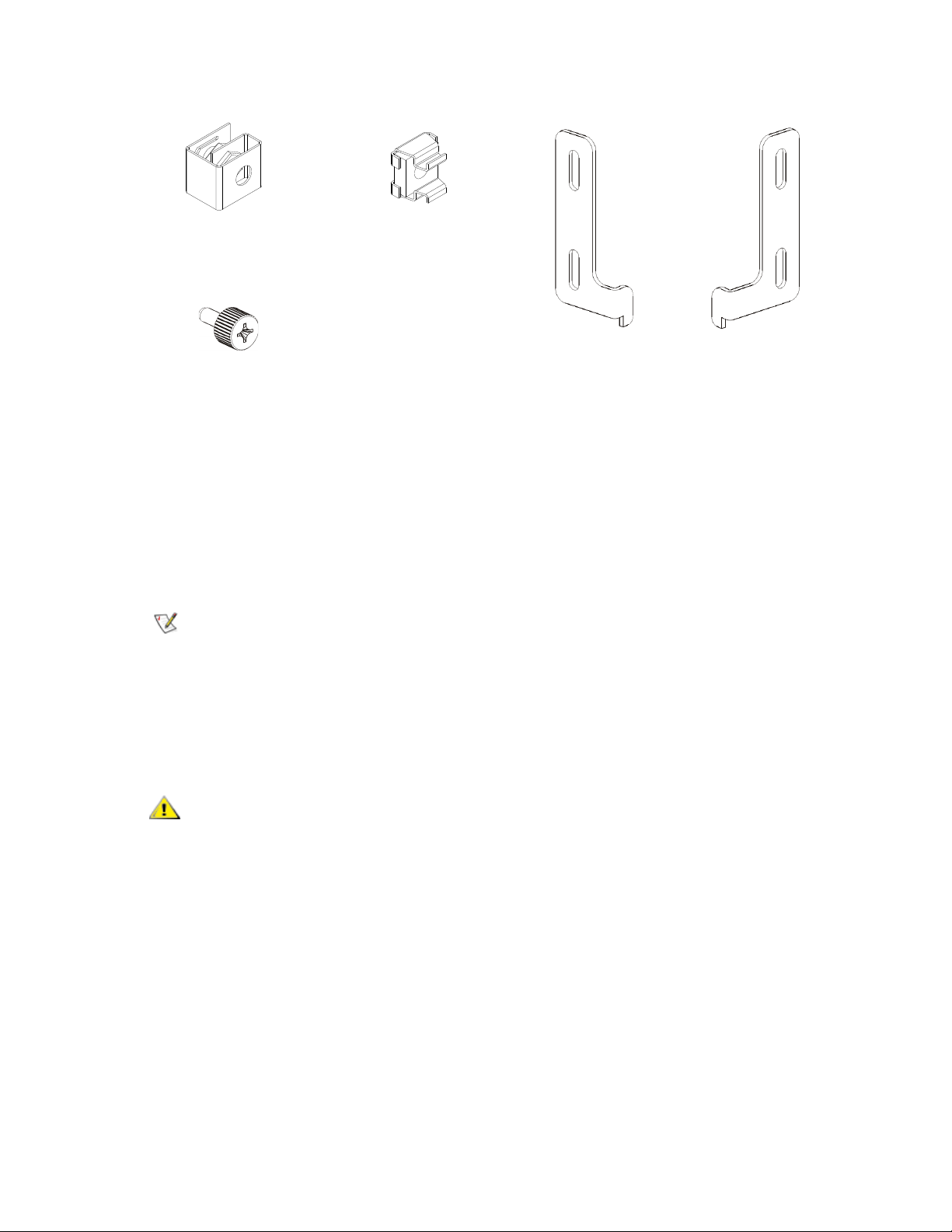
Rack Ear Kit Contents
Note
CAUTION
M5 thumbscrew — Secures
the rack ears. Quantity: 4
Rack ear, left — Holds
the bottom module in the
rack. Quantity: 1
Rack ear, right — Holds
the bottom module in the
rack. Quantity: 1
Nut clip — Used in racks
with square holes.
Quantity: 4
Cage nut — Used in racks
with round holes.
Quantity: 4
1 Upgrade the library firmware to a level that can support the number of modules you are adding. See the
Scalar i500 User’s Guide for information on upgrading firmware.
2 Remove all tape cartridges from the library using the import and export commands of the operator panel
or web client.
3 Power off the library.
4 Disconnect all power cords, network data cables, and module-to-module cables from all of the modules.
You should label all cables before you remove them so you can later
reconnect them to their proper locations.
5 Park the robot assembly in the control module. Before unstacking the library, the robot assembly must
be placed in the control module.
a. Open the I/E station and access doors of each module.
b. Using your hands, gently lift the robot assembly into the control module. The robot assembly
should glide slowly and with some resistance.
Support the robot assembly by holding onto the broad metal X-axis
plate. Lifting the robot by the thin metal rod will bend the rod. Lifting
the robot by the black plastic picker body can damage the robot.
c. After raising the robot assembly to the approximate middle of the control module, hold it in place
with one hand and, using your other hand, move the parking tab to the "parked" position.
(Depending on your library, you will have one of two parking tabs. If your robot has an “M2” label
on the front, you have the Model 2 parking tab. Model 1 parking tab: swivel toward you; Model
2 parking tab: counter-clockwise direction). The metal parking tab is located at the bottom of
column 1.
d. Gently release the robot assembly to rest on the parking tab.
Installation Instructions: Expansion Module 3
Page 4
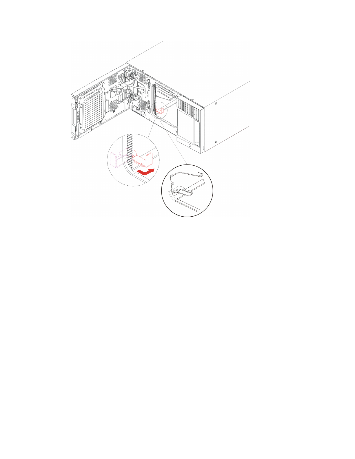
Figure 1 Parking the Robot Assembly
Model 2 tab
Model 1 tab
6 Remove all power supplies from each module. For instructions, see the user’s guide.
7 Remove all tape drives from each module. For instructions, see the user’s guide.
4 Installation Instructions: Expansion Module
Page 5
Unstacking the Existing Modules
CAUTION
Note
Front Y-rail
Rear Y-rail
Y-rail (this end up)
Squeeze here
to release
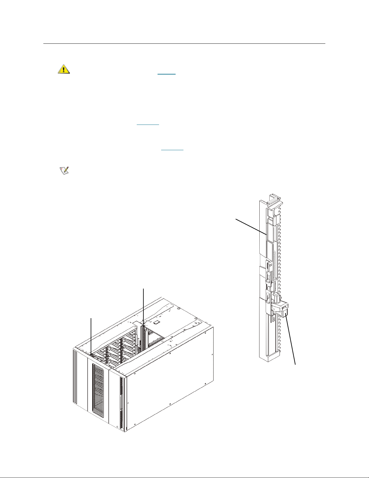
1 Starting with the topmost module of your library, open the I/E station and access doors.
Before unstacking the modules, the robot assembly must be parked
as described in Step 5
2 If your current configuration already uses an expansion module, disengage the Y-rails so the modules
can be safely unstacked.
a. From the front of the library, find the Y-rail release mechanism, which is located on the left side
of the module. Squeeze the handle of the Y-rail release mechanism, lift it, and release it so that
it locks into place (see Figure 2
b. From the rear of the library, find the rear Y-rail release mechanism located in the interior of the
right side of the module. Squeeze the handle of the Y-rail release mechanism, lift it, and release
it so that it locks into place (see Figure 2
The rear Y-rail is impossible to lift up with the tape drives installed.
Figure 2 Expansion Module Y-rails
on page 3.
).
).
Installation Instructions: Expansion Module 5
Page 6

3 Remove the rack ears that fasten the module to the rack. Retain the rack ears, M5 thumbscrews, and
cage nuts or nut clips (if installed) to reinstall later.
4 Loosen the thumbscrews located at the base of the front and rear of the module (see Figure 3
Figure 3 Module Thumbscrew Location
).
6 Installation Instructions: Expansion Module
Page 7

5 Open the module’s access door and raise the guide pin by pulling it up and turning it slightly as if it were
CAUTION
a screw. Otherwise, the guide pin may scratch the front doors of the module beneath it (see Figure 4
Figure 4 Guide Pin Location
6 From the front of the library, slide the entire module toward you and lift it off of the module below it.
).
7 Repeat these steps for each module that you need to remove.
Installing the New Expansion Module
1 Prepare the rack to hold modules, if you want to install your library in a rack. See the Scalar i500 User’s
Guide or the CRU instruction sheet, Installation Instructions: Rackmount Kit, for instructions on installing
a rackmount kit.
2 Remove and replace the cover plates, if appropriate.
Before removing the control module’s bottom cover plate, the robot
assembly must be parked as described in Step 5
a. If you plan to stack the control module at the top of the library, and if an expansion module is
located below it, remove the control module’s bottom cover plate and the expansion module’s
top cover plate.
b. If you plan to stack the control module between expansion modules, remove both the top and
bottom cover plates of the control module. Also remove the top cover plate of the expansion
module located below the control module and the bottom cover plate of the expansion module
located above the control module.
c. If you plan to stack the control module at the bottom of the library, and if an expansion module
will be located above it, remove the control module’s top cover plate and the expansion
module’s bottom cover plate.
on page 3.
Installation Instructions: Expansion Module 7
Page 8

Table 1 Cover Plate Location after Adding an Expansion Module
Note
5U 14U 23U 32U 41U
top cover plate
top cover plate NEW Expansion
top cover plate Control Module Control Module
top cover plate Control Module Expansion
Module
top cover plate Control Module Expansion
Module
Control Module NEW Expansion
Module
bottom cover
plate
a. Recommended location for adding an expansion module.
bottom cover
plate
a
NEW Expansion
Module
a
bottom cover
plate
Expansion
Module
NEW Expansion
Module
bottom cover
plate
3 Determine where in the rack to install the nut clips (or cage nuts).
Consider using the following method to determine where to install the nut
clips (or cage nuts) rather than adding the module to the rack first. If you
add the module to the rack first, installing the nut clips (or cage nuts) can
be difficult because rack space has become restricted.
a. If you are adding a module above a previously racked expansion module, count nine full units
from the location of the expansion module’s rack ears, and prepare to install the nut clip (or
cage nut) to that location on the rack.
Module
a
Expansion
Module
Expansion
Module
a
Expansion
Module
bottom cover
plate
For example, if the expansion module’s rack ears are located at 1U and 2U, then the nut clips
(or cage nuts) should be installed at 10U and 11U.
Next, determine which holes you must use within the 10U and 11U markers. Notice that each
rack unit (U), as delineated by the alignment markers in the rack, contains three mounting
holes. If you are adding a module anywhere above the control module, position the nut clip (or
cage nut) at the middle hole in that unit. If you are adding a module anywhere below the control
module, position the nut clip (or cage nut) at the upper hole in that unit.
b. If you are adding a module directly above a previously racked control module, count five full
units from the location of the control module’s rack ears, and prepare to install the nut clip (or
cage nut) to that location on the rack.
For example, if the control module’s rack ears are located at 1U and 2U, then the nut clips (or
cage nuts) should be installed at 6U and 7U.
Next, determine which holes you must use within the 6U and 7U markers. Notice that each rack
unit, as delineated by the alignment markers in the rack, contains three mounting holes. If you
are adding a module anywhere above the control module, position the nut clip (or cage nut) at
the middle hole in that unit. If you are adding a module anywhere below the control module,
position the nut clip (or cage nut) at the upper hole in that unit.
8 Installation Instructions: Expansion Module
Page 9

4 Install the nut clips (or cage nuts) to the desired location in the rack.
Installing nut clips:
a. Hold the nut clip so that its semi-circle design faces outside the rack.
b. Push the nut clip onto the rack’s mounting holes so that the nut is behind the rack’s holes. (After
the nut clip is installed, you can slide it up and down the mounting holes, if necessary.)
Installing cage nuts:
a. Hold the cage nut so that its hinges face outside the rack, and so that its hinges clasp the upper
and lower portions of the square hole.
b. Place the cage nut in the desired hole. Insert one hinge in the hole first, then pinch the cage nut
and push it into the hole until it snaps into place. (You may want to use a screwdriver to help
push the hinge into the hole.)
5 Prepare the module to be stacked in the rack.
a. Power off the module and disconnect all power cords, network data cables, and module-to-
module cables.
b. Consider removing all tape drives from the module. Modules are much easier to lift into the rack
without the additional weight of the tape drives.
c. Open the module’s access door and raise the guide pin by pulling it up and turning it slightly as
if it were a screw (see Figure 5
). Otherwise, the guide pin may scratch the front doors of the
module on which you are stacking it.
Installation Instructions: Expansion Module 9
Page 10

Figure 5 Guide Pin Location
6 Lift the new expansion module and, from the front of the library, place it in the desired location.
7 If there is already a module installed, secure the two modules together by tightening the two
thumbscrews at the base of the front of the module and the two thumbscrews located at the base of the
back of the module. Then lower the module’s guide pin (located at the base of the front of the module)
by turning it and pushing it down.
8 Tighten all thumbscrews located at the base of the front and back of the modules.
10 Installation Instructions: Expansion Module
Page 11

9 Install the right rack ear. At the front of the library:
Rack ear hinges
a. Open the I/E station door. At the lower right corner of the module is a vertical slot. Insert the
hinge of the right rack ear into the slot and then position the holes of the rack ear flush with the
rack rail.
b. Using two M5 thumbscrews, fasten the rack ear to the rack. The thumbscrews should thread
through the nut clips (or cage nuts) and fasten completely and evenly.
Installation Instructions: Expansion Module 11
Page 12

10 Install the left rack ear.
Note
a. With the I/E station door open, open the left door (the access door) of the module and pull the
door toward you in order to access the slot located in the lower left corner of the module. (The
flexible door hinge allows the door to be pulled away from the module, providing access to the
slot.)
You may need to pull the door toward you in order to access the slot.
b. Install the left rack ear in the same manner as the right rack ear.
c. Using two M5 thumbscrews, fasten the rack ear to the rack. The thumbscrews should thread
through the nut clips (or cage nuts) and fasten completely and evenly.
11 Engage the Y-rails of the new module in your library configuration. Ensure that the Y-rails are properly
aligned and the thumbscrews are tightened (see Figure 6
12 Installation Instructions: Expansion Module
).
Page 13

Figure 6 Expansion Module Y-rails
CAUTION
Front Y-rail
Rear Y-rail
Y-rail (this end up)
Squeeze here
to release
a. From the front of the library, open the I/E station and access doors of the expansion module.
b. Squeeze the handle of the Y-rail release mechanism, lift it out of its locked position, and slide
it downward as far as it will go.
c. From the back of the library, find the rear Y-rail release mechanism, which is located in the
interior of the right side of the module. Squeeze the handle of the Y-rail release mechanism, lift
it out of its locked position, and slide it downward as far as it will go (see Figure 7
).
Doing this aligns the Y-rails with the Y-rails of the module beneath it.
Check to make sure that there is no gap between the top and bottom
Y-rails on both the front and back of the library. If a gap exists, the
library cannot mechanically initialize.
Installation Instructions: Expansion Module 13
Page 14

Figure 7 Y-rail in Unlocked, Functional Position
CAUTION
12 Repeat these steps for each module you need to re-install in the library configuration.
Preparing to Use the Library
1 Add the tape drives to the modules. For details, see the Scalar i500 User’s Guide.
2 Add the power supplies. For details, see the Scalar i500 User’s Guide.
3 If your library contains FC I/O blades, install both the I/O blades and the accompanying fan blades in
the expansion module. For details, see the Scalar i500 User’s Guide.
4 Unpark the robot assembly.
a. Gently raise the robot assembly so that it no longer rests on the parking tab.
Support the robot assembly by holding onto the broad metal X-axis
plate. Lifting the robot by the thin metal rod will bend the rod. Lifting
the robot by the black plastic picker body can damage the robot.
b. With your free hand, move the parking tab to the "unparked" position so that it is removed
completely from the interior of the module. (Depending on your library, you will have one of two
parking tabs. If your robot has an “M2” label on the front, you have the Model 2 parking tab.
Model 1 parking tab: swivel the parking tab away from you; Model 2 parking tab: move in a
clockwise direction). When replaced correctly, the parking tab will not accidentally swivel into
the path of the robot.
c. Gently release the robot assembly. It will lower to the bottom module of the library.
14 Installation Instructions: Expansion Module
Page 15

Figure 8 Unparking the Robot Assembly
Model 2 tab
Model 1 tab
5 Connect all power cords, network data cables, and module-to-module cables. Make sure the module
terminators are installed at the top and bottom of the stack of modules. For complete cabling
instructions, see the Scalar i500 User’s Guide.
6 Power on the library.
7 If you replaced the expansion module, follow these additional steps (if you did not replace the
expansion module, but simply added a new one, go to Step 8
):
a. Delete all partitions that contained slots in the bad expansion module.
b. Delete all cleaning slots from the library (set to zero).
c. Empty and delete all I/E station slots from the library (set to zero).
d. Reboot the library.
e. Re-create partitions, cleaning slots, and I/E station slots as desired.
f. Go to Step 9
.
8 Reconfigure the library, including applying the new COD license key, using the operator panel or web
client. (If you replaced the expansion module, the license key remains the same, so skip this step.)
9 Add the tape cartridges to the library’s modules using the I/E station commands from the operator panel
or web client.
10 Open the host application and reinventory in order to synchronize its logical inventory with the physical
inventory of the library.
Installation Instructions: Expansion Module 15
 Loading...