

Page 1

User’s Guide
Quantum Scalar
i
40 and Scalar i80
6-66545-10 Rev A
Page 2

Scalar i40 and Scalar i80 User’s Guide, 6-66545-10 Rev A, August 2014, Product of U.S.A.
Quantum Corporation provides this publication “as is” without warranty of any kind, either express or
implied, including but not limited to the implied warranties of merchantability or fitness for a particular
purpose. Quantum Corporation may revise this publication from time to time without notice.
Printed in USA.
COPYRIGHT STATEMENT
Copyright 2014 by Quantum Corporation. All rights reserved.
Your right to copy this manual is limited by copyright law. Making copies or adaptations without prior
written authorization of Quantum Corporation is prohibited by law and constitutes a punishable
violation of the law.
TRADEMARK STATEMENT
Quantum, the Quantum logo, and Scalar are registered trademarks of Quantum Corporation, registered
in the U.S.A. and other countries.
Preserving the World’s Most Important Data. Yours., StorageCare, and Vision are trademarks of
Quantum.
LTO and Ultrium are trademarks of , IBM, and Quantum in the U.S.A. and other countries. All other
trademarks are the property of their respective companies.
Specifications are subject to change without notice.
ii Quantum Scalar i40 and Scalar i80 User’s Guide
Page 3

Contents
Preface xix
Taking ESD Precautions. . . . . . . . . . . . . . . . . . . . . . . . . . . . . xxiii
Worldwide End-User Product Warranty . . . . . . . . . . . . . . . . xxvi
Scalar i40 and i80 Supported Versions . . . . . . . . . . . . . . . . .xxvii
Chapter 1 Description 1
Overview . . . . . . . . . . . . . . . . . . . . . . . . . . . . . . . . . . . . . . . . . . . . . . . . 1
Library Components . . . . . . . . . . . . . . . . . . . . . . . . . . . . . . . . . . . . . . . 2
Front Panel . . . . . . . . . . . . . . . . . . . . . . . . . . . . . . . . . . . . . . . . 2
Robotic System and Barcode Scanner . . . . . . . . . . . . . . . . . . . . 3
Magazines . . . . . . . . . . . . . . . . . . . . . . . . . . . . . . . . . . . . . . . . 4
Power Supply . . . . . . . . . . . . . . . . . . . . . . . . . . . . . . . . . . . . . . 8
System Control Board . . . . . . . . . . . . . . . . . . . . . . . . . . . . . . . . 8
Tape Drives . . . . . . . . . . . . . . . . . . . . . . . . . . . . . . . . . . . . . . . . 9
Standard Features . . . . . . . . . . . . . . . . . . . . . . . . . . . . . . . . . . . . . . . . 11
User Interface . . . . . . . . . . . . . . . . . . . . . . . . . . . . . . . . . . . . . 11
Partitions . . . . . . . . . . . . . . . . . . . . . . . . . . . . . . . . . . . . . . . . 11
Control Path Modification. . . . . . . . . . . . . . . . . . . . . . . . . . . . 11
Support for WORM . . . . . . . . . . . . . . . . . . . . . . . . . . . . . . . . . 12
Licensable Features . . . . . . . . . . . . . . . . . . . . . . . . . . . . . . . . . . . . . . . 12
Capacity on Demand (COD) . . . . . . . . . . . . . . . . . . . . . . . . . . 12
Quantum Scalar i40 and Scalar i80 User’s Guide iii
Page 4

Contents
Advanced Reporting . . . . . . . . . . . . . . . . . . . . . . . . . . . . . . . . 13
Encryption Key Management . . . . . . . . . . . . . . . . . . . . . . . . . 14
Chapter 2 Unpacking the Library 15
Chapter 3 Understanding the User Interface 19
Operator Panel . . . . . . . . . . . . . . . . . . . . . . . . . . . . . . . . . . . . . . . . . . 19
Operator Panel Layout and Functions . . . . . . . . . . . . . . . . . . . 20
Navigating and Editing on the Operator Panel . . . . . . . . . . . . 25
Web Client. . . . . . . . . . . . . . . . . . . . . . . . . . . . . . . . . . . . . . . . . . . . . . 26
Tips . . . . . . . . . . . . . . . . . . . . . . . . . . . . . . . . . . . . . . . . . . . . . 26
Sorting Information in Tables . . . . . . . . . . . . . . . . . . . . . . . . . 27
Web Client Layout and Functions . . . . . . . . . . . . . . . . . . . . . . 27
Web Client Home Page . . . . . . . . . . . . . . . . . . . . . . . . . . . . . . 29
System Summary . . . . . . . . . . . . . . . . . . . . . . . . . . . . . . . . . . 30
Subsystem Status . . . . . . . . . . . . . . . . . . . . . . . . . . . . . . . . . . 30
Menu Trees . . . . . . . . . . . . . . . . . . . . . . . . . . . . . . . . . . . . . . . . . . . . . 31
Chapter 4 Configuring the Library 35
Using the Setup Wizard. . . . . . . . . . . . . . . . . . . . . . . . . . . . . . . . . . . . 37
Default Configuration . . . . . . . . . . . . . . . . . . . . . . . . . . . . . . . . . . . . . 38
Configuring Network Settings . . . . . . . . . . . . . . . . . . . . . . . . . . . . . . . 38
Library Host Name . . . . . . . . . . . . . . . . . . . . . . . . . . . . . . . . . 39
DHCP . . . . . . . . . . . . . . . . . . . . . . . . . . . . . . . . . . . . . . . . . . . 40
IP Addresses . . . . . . . . . . . . . . . . . . . . . . . . . . . . . . . . . . . . . . 40
Default Gateway, Subnet Mask, Network Prefix, and DNS
Addresses . . . . . . . . . . . . . . . . . . . . . . . . . . . . . . . . . . . . . . . . 41
Configuring SNMP Settings . . . . . . . . . . . . . . . . . . . . . . . . . . . . . . . . . 42
Registering External Management Applications . . . . . . . . . . . 42
Enabling SNMP Versions . . . . . . . . . . . . . . . . . . . . . . . . . . . . . 44
Enabling SNMP Authentication Traps . . . . . . . . . . . . . . . . . . . 44
Modifying the SNMP Community String . . . . . . . . . . . . . . . . . 45
Downloading the SNMP MIB. . . . . . . . . . . . . . . . . . . . . . . . . . 45
iv Quantum Scalar i40 and Scalar i80 User’s Guide
Page 5

Contents
Setting the Date, Time, and Time Zone . . . . . . . . . . . . . . . . . . . . . . . . 46
Setting the Date and Time Manually. . . . . . . . . . . . . . . . . . . . 47
Setting the Date and Time Using the Network Time Protocol . 47
Setting the Time Zone. . . . . . . . . . . . . . . . . . . . . . . . . . . . . . . 48
Setting Daylight Saving Time . . . . . . . . . . . . . . . . . . . . . . . . . 49
Working With Partitions . . . . . . . . . . . . . . . . . . . . . . . . . . . . . . . . . . . 49
Automatically Creating Partitions . . . . . . . . . . . . . . . . . . . . . . 51
Manually Creating Partitions. . . . . . . . . . . . . . . . . . . . . . . . . . 52
Modifying Partitions . . . . . . . . . . . . . . . . . . . . . . . . . . . . . . . . 55
Deleting Partitions . . . . . . . . . . . . . . . . . . . . . . . . . . . . . . . . . 55
Viewing the Current Partitions . . . . . . . . . . . . . . . . . . . . . . . . 56
Changing Access to Partitions. . . . . . . . . . . . . . . . . . . . . . . . . 57
Taking a Partition Online or Offline. . . . . . . . . . . . . . . . . . . . . 57
Configuring Cleaning Slots . . . . . . . . . . . . . . . . . . . . . . . . . . . . . . . . . 59
Configuring I/E Station Slots . . . . . . . . . . . . . . . . . . . . . . . . . . . . . . . . 62
Configuring Tape Drive Parameters . . . . . . . . . . . . . . . . . . . . . . . . . . . 64
Configuring Control Paths. . . . . . . . . . . . . . . . . . . . . . . . . . . . . . . . . . 66
Adding or Upgrading Licensable Features . . . . . . . . . . . . . . . . . . . . . . 68
About License Keys . . . . . . . . . . . . . . . . . . . . . . . . . . . . . . . . . 68
Viewing Your License Keys . . . . . . . . . . . . . . . . . . . . . . . . . . . 69
Viewing Installed Licenses. . . . . . . . . . . . . . . . . . . . . . . . . . . . 69
Obtaining a License Key . . . . . . . . . . . . . . . . . . . . . . . . . . . . . 69
Applying a License Key . . . . . . . . . . . . . . . . . . . . . . . . . . . . . . 70
Working With E-mail Notifications . . . . . . . . . . . . . . . . . . . . . . . . . . . 71
Creating E-mail Notifications . . . . . . . . . . . . . . . . . . . . . . . . . 72
Modifying E-mail Notifications . . . . . . . . . . . . . . . . . . . . . . . . 73
Deleting E-mail Notifications . . . . . . . . . . . . . . . . . . . . . . . . . 74
Configuring the Library E-Mail Account. . . . . . . . . . . . . . . . . . . . . . . . 75
Setting Customer Contact Information . . . . . . . . . . . . . . . . . . . . . . . . 77
Configuring the Service Port . . . . . . . . . . . . . . . . . . . . . . . . . . . . . . . . 78
Working With Local User Accounts and Passwords . . . . . . . . . . . . . . . 79
Using the Web Client Default Administrator Account. . . . . . . 79
Privilege Levels . . . . . . . . . . . . . . . . . . . . . . . . . . . . . . . . . . . . 80
Creating Local User Accounts on the Web Client . . . . . . . . . . 81
Modifying Local User Accounts on the Web Client . . . . . . . . . 82
Deleting Local User Accounts on the Web Client . . . . . . . . . . 83
Enabling and Creating Passwords on the Operator Panel . . . . 83
Disabling Passwords on the Operator Panel . . . . . . . . . . . . . . 86
Quantum Scalar i40 and Scalar i80 User’s Guide v
Page 6

Contents
Modifying Passwords on the Operator Panel . . . . . . . . . . . . . 86
Resetting Passwords on the Operator Panel . . . . . . . . . . . . . . 87
Working With LDAP User Accounts (Remote Authentication) . . . . . . . 87
Local Authentication vs. Remote Authentication . . . . . . . . . . 87
LDAP Server Guidelines . . . . . . . . . . . . . . . . . . . . . . . . . . . . . . 88
Configuring Secure LDAP on the Library . . . . . . . . . . . . . . . . . 89
Configuring LDAP on the Library . . . . . . . . . . . . . . . . . . . . . . 89
Testing LDAP Settings . . . . . . . . . . . . . . . . . . . . . . . . . . . . . . . 93
Configuring Kerberos . . . . . . . . . . . . . . . . . . . . . . . . . . . . . . . 93
Generating the Kerberos Service Keytab File . . . . . . . . . . . . . . 95
Setting the Session Timeout . . . . . . . . . . . . . . . . . . . . . . . . . . . . . . . . 96
Configuring System Settings . . . . . . . . . . . . . . . . . . . . . . . . . . . . . . . . 97
Unload Assist . . . . . . . . . . . . . . . . . . . . . . . . . . . . . . . . . . . . . 97
Logical Serial Number Addressing. . . . . . . . . . . . . . . . . . . . . . 98
Manual Cartridge Assignment . . . . . . . . . . . . . . . . . . . . . . . . 99
SNMP . . . . . . . . . . . . . . . . . . . . . . . . . . . . . . . . . . . . . . . . . . 100
SMI-S . . . . . . . . . . . . . . . . . . . . . . . . . . . . . . . . . . . . . . . . . . 100
Power Save . . . . . . . . . . . . . . . . . . . . . . . . . . . . . . . . . . . . . . 101
Configuring Security Settings . . . . . . . . . . . . . . . . . . . . . . . . . . . . . . 102
Network Interface . . . . . . . . . . . . . . . . . . . . . . . . . . . . . . . . . 102
SSH Services . . . . . . . . . . . . . . . . . . . . . . . . . . . . . . . . . . . . . 103
Internet Control Message Protocol (ICMP) . . . . . . . . . . . . . . 103
Remote Access Via Web Client . . . . . . . . . . . . . . . . . . . . . . . 104
Remote Service Login . . . . . . . . . . . . . . . . . . . . . . . . . . . . . . 104
SNMP V1/V2 . . . . . . . . . . . . . . . . . . . . . . . . . . . . . . . . . . . . . 104
SSL . . . . . . . . . . . . . . . . . . . . . . . . . . . . . . . . . . . . . . . . . . . . 105
Saving and Restoring the Library Configuration . . . . . . . . . . . . . . . . 106
Saving the Library Configuration . . . . . . . . . . . . . . . . . . . . . 106
Restoring the Library Configuration . . . . . . . . . . . . . . . . . . . 107
Registering the Library. . . . . . . . . . . . . . . . . . . . . . . . . . . . . . . . . . . . 108
Changing Operator Panel Home Screen View . . . . . . . . . . . . . . . . . . 108
Changing to Alternate Home Screen. . . . . . . . . . . . . . . . . . . 108
Returning to Default Home Screen . . . . . . . . . . . . . . . . . . . . 109
Chapter 5 Advanced Reporting 111
Advanced Reporting Features . . . . . . . . . . . . . . . . . . . . . . . . . . . . . . 112
Required Firmware . . . . . . . . . . . . . . . . . . . . . . . . . . . . . . . . 113
vi Quantum Scalar i40 and Scalar i80 User’s Guide
Page 7

Contents
Working with Control Path Failover (CPF) . . . . . . . . . . . . . . . . . . . . . 113
Prerequisites . . . . . . . . . . . . . . . . . . . . . . . . . . . . . . . . . . . . . 113
Configuring CPF . . . . . . . . . . . . . . . . . . . . . . . . . . . . . . . . . . 114
Forcing CPF . . . . . . . . . . . . . . . . . . . . . . . . . . . . . . . . . . . . . . 115
Using Advanced Reporting Reports . . . . . . . . . . . . . . . . . . . . . . . . . . 117
Configuring the Drive Resource Utilization Report . . . . . . . . 118
Configuring the Media Integrity Analysis Report. . . . . . . . . . 120
Using Advanced Reporting Templates. . . . . . . . . . . . . . . . . . 123
Loading and Reloading Advanced Reporting Data . . . . . . . . 124
Deleting Advanced Reporting Data. . . . . . . . . . . . . . . . . . . . 125
Saving and E-mailing Advanced Reporting Data Files . . . . . . 125
Working with the Media Security Log . . . . . . . . . . . . . . . . . . . . . . . . 126
Configuring Media Security . . . . . . . . . . . . . . . . . . . . . . . . . 127
Viewing, Saving, and E-mailing Media Security Log . . . . . . . 128
Viewing the Media Usage Log. . . . . . . . . . . . . . . . . . . . . . . . . . . . . . 129
Automatically E-mailing Advanced Reporting Reports and Logs . . . . 130
Creating a Recipient . . . . . . . . . . . . . . . . . . . . . . . . . . . . . . . 131
Modifying a Recipient . . . . . . . . . . . . . . . . . . . . . . . . . . . . . . 134
Deleting a Recipient . . . . . . . . . . . . . . . . . . . . . . . . . . . . . . . 134
Chapter 6 Performing Library Operations 135
Logging In . . . . . . . . . . . . . . . . . . . . . . . . . . . . . . . . . . . . . . . . . . . . . 136
Simultaneous Logins. . . . . . . . . . . . . . . . . . . . . . . . . . . . . . . 136
Logging in for the First Time. . . . . . . . . . . . . . . . . . . . . . . . . 136
Logging in Using the Operator Panel . . . . . . . . . . . . . . . . . . 137
Logging in Via the Web Client . . . . . . . . . . . . . . . . . . . . . . . 137
Logging in When LDAP or Kerberos is Enabled . . . . . . . . . . . 138
Logging Out . . . . . . . . . . . . . . . . . . . . . . . . . . . . . . . . . . . . . . . . . . . 138
Shutting Down, Restarting, Turning Off, and Removing Power. . . . . 139
Shutting Down the Library . . . . . . . . . . . . . . . . . . . . . . . . . . 140
Restarting the Library . . . . . . . . . . . . . . . . . . . . . . . . . . . . . . 142
Turning Off the Library . . . . . . . . . . . . . . . . . . . . . . . . . . . . . 143
Completely Removing Library Power. . . . . . . . . . . . . . . . . . . 144
Emergency Power-off Procedure. . . . . . . . . . . . . . . . . . . . . . 144
Taking the Library Offline . . . . . . . . . . . . . . . . . . . . . . . . . . . 145
Unlocking and Opening the I/E Station . . . . . . . . . . . . . . . . . . . . . . . 145
Quantum Scalar i40 and Scalar i80 User’s Guide vii
Page 8

Contents
Releasing Magazines . . . . . . . . . . . . . . . . . . . . . . . . . . . . . . . . . . . . . 148
Releasing Magazines via the User Interface. . . . . . . . . . . . . . 149
Releasing Magazines Manually . . . . . . . . . . . . . . . . . . . . . . . 150
Performing Media Operations . . . . . . . . . . . . . . . . . . . . . . . . . . . . . . 151
Importing Tape Cartridges . . . . . . . . . . . . . . . . . . . . . . . . . . 152
Bulk Loading Tape Cartridges . . . . . . . . . . . . . . . . . . . . . . . . 155
Moving Tape Cartridges . . . . . . . . . . . . . . . . . . . . . . . . . . . . 156
Exporting Tape Cartridges. . . . . . . . . . . . . . . . . . . . . . . . . . . 158
Loading Tape Drives . . . . . . . . . . . . . . . . . . . . . . . . . . . . . . . 160
Unloading Tape Drives . . . . . . . . . . . . . . . . . . . . . . . . . . . . . 161
Cleaning Tape Drives . . . . . . . . . . . . . . . . . . . . . . . . . . . . . . . . . . . . . 163
Valid Cleaning Cartridges . . . . . . . . . . . . . . . . . . . . . . . . . . . 164
About AutoClean . . . . . . . . . . . . . . . . . . . . . . . . . . . . . . . . . 165
Enabling AutoClean . . . . . . . . . . . . . . . . . . . . . . . . . . . . . . . 165
Importing Cleaning Cartridges . . . . . . . . . . . . . . . . . . . . . . . 166
Exporting Cleaning Cartridges . . . . . . . . . . . . . . . . . . . . . . . 168
Manually Cleaning Tape Drives . . . . . . . . . . . . . . . . . . . . . . . 170
Taking a Tape Drive Online or Offline . . . . . . . . . . . . . . . . . . . . . . . . 172
Chapter 7 Encryption Key Management 175
General Notes About Encryption on the Library . . . . . . . . . . . . . . . . 176
About the EKM License . . . . . . . . . . . . . . . . . . . . . . . . . . . . . . . . . . . 177
KMIP-compliant Encryption Key Management. . . . . . . . . . . . . . . . . . 177
About Key Reuse . . . . . . . . . . . . . . . . . . . . . . . . . . . . . . . . . . . . . . . . 178
Configuring Scalar Key Manager (SKM) on the Library . . . . . . . . . . . 179
Step 1: Upgrade Firmware . . . . . . . . . . . . . . . . . . . . . . . . . . 179
Step 2: Install the EKM License Key on the Library . . . . . . . . 180
Step 3: Prepare Partitions for Library Managed Encryption. . 180
Step 4: Configure Encryption Settings and Key Server
Addresses . . . . . . . . . . . . . . . . . . . . . . . . . . . . . . . . . . . . . . . 180
Step 5: Install TLS Communication Certificates on the
Library. . . . . . . . . . . . . . . . . . . . . . . . . . . . . . . . . . . . . . . . . . 183
Step 6: Run EKM Path Diagnostics . . . . . . . . . . . . . . . . . . . . 183
Step 7: Configure Partitions for Library Managed Encryption183
Step 8: Save the Library Configuration . . . . . . . . . . . . . . . . . 186
viii Quantum Scalar i40 and Scalar i80 User’s Guide
Page 9

Contents
EKM Path Diagnostics . . . . . . . . . . . . . . . . . . . . . . . . . . . . . . . . . . . . 186
Description . . . . . . . . . . . . . . . . . . . . . . . . . . . . . . . . . . . . . . 186
Failure Scenarios . . . . . . . . . . . . . . . . . . . . . . . . . . . . . . . . . . 187
Running Manual EKM Path Diagnostics . . . . . . . . . . . . . . . . 187
Enabling Automatic EKM Path Diagnostics . . . . . . . . . . . . . . 188
Viewing Tape Drive Encryption Settings . . . . . . . . . . . . . . . . . . . . . . 189
Installing TLS Certificates on the Library . . . . . . . . . . . . . . . . . . . . . . 189
Checking for Current Certificates . . . . . . . . . . . . . . . . . . . . . 190
Installing Quantum-Supplied TLS Certificates on the Library. 191
Installing Your Own TLS Certificates on the Library. . . . . . . . 193
Performing Scalar Key Manager Functions Available on the Library . 196
Generating Data Encryption Keys . . . . . . . . . . . . . . . . . . . . . 199
Sharing Encrypted Tape Cartridges . . . . . . . . . . . . . . . . . . . . 203
Exporting Encryption Certificates . . . . . . . . . . . . . . . . . . . . . 204
Importing Encryption Certificates . . . . . . . . . . . . . . . . . . . . . 205
Exporting Data Encryption Keys . . . . . . . . . . . . . . . . . . . . . . 206
Importing Data Encryption Keys . . . . . . . . . . . . . . . . . . . . . . 208
Accessing the SKM Server Logs . . . . . . . . . . . . . . . . . . . . . . . 209
Using the SKM Encryption Key Import Warning Log . . . . . . . 210
Viewing Audit Logs. . . . . . . . . . . . . . . . . . . . . . . . . . . . . . . . 211
Performing KMIP Key Manager Functions on the Library. . . . . . . . . . 213
Viewing and Changing the Active Key Server . . . . . . . . . . . . 213
Chapter 8 Getting Information About the Library 215
Viewing Library Information . . . . . . . . . . . . . . . . . . . . . . . . . . . . . . . 216
Viewing System Information . . . . . . . . . . . . . . . . . . . . . . . . . . . . . . . 216
Viewing the Location of the Robot . . . . . . . . . . . . . . . . . . . . . . . . . . 217
Viewing the Library Configuration Report . . . . . . . . . . . . . . . . . . . . . 220
Saving and E-mailing the Library Configuration Record. . . . . . . . . . . 222
Saving the Configuration Record . . . . . . . . . . . . . . . . . . . . . 223
E-mailing the Configuration Record . . . . . . . . . . . . . . . . . . . 223
Viewing the Network Settings Report . . . . . . . . . . . . . . . . . . . . . . . . 224
Viewing the Logged in Users Report . . . . . . . . . . . . . . . . . . . . . . . . . 224
Viewing the All Slots Report . . . . . . . . . . . . . . . . . . . . . . . . . . . . . . . 225
Quantum Scalar i40 and Scalar i80 User’s Guide ix
Page 10

Contents
Viewing, Saving, and E-mailing Library Logs . . . . . . . . . . . . . . . . . . . 226
Cleaning Log. . . . . . . . . . . . . . . . . . . . . . . . . . . . . . . . . . . . . 227
Diagnostic Tickets Log . . . . . . . . . . . . . . . . . . . . . . . . . . . . . 227
Media Security Log (with Advanced Reporting License) . . . . 228
Media Usage Log (with Advanced Reporting License). . . . . . 228
SKM Encryption Key Import Warning Log (with EKM
License). . . . . . . . . . . . . . . . . . . . . . . . . . . . . . . . . . . . . . . . . 229
Tape Drive Log . . . . . . . . . . . . . . . . . . . . . . . . . . . . . . . . . . . 229
Viewing Library Information on the Operator Panel . . . . . . . . . . . . . 231
Viewing Partition Information. . . . . . . . . . . . . . . . . . . . . . . . 231
Viewing Tape Drive Information . . . . . . . . . . . . . . . . . . . . . . 231
Viewing Network Settings. . . . . . . . . . . . . . . . . . . . . . . . . . . 232
Viewing the Date, Time, and Time Zone . . . . . . . . . . . . . . . . 232
Viewing Licenses. . . . . . . . . . . . . . . . . . . . . . . . . . . . . . . . . . 232
Using Advanced Reporting Features . . . . . . . . . . . . . . . . . . . . . . . . . 233
Viewing the Open Source License Agreement . . . . . . . . . . . . . . . . . . 233
Viewing the Copyright Statement . . . . . . . . . . . . . . . . . . . . . . . . . . . 233
Chapter 9 Updating Firmware 235
Updating Library Firmware . . . . . . . . . . . . . . . . . . . . . . . . . . . . . . . . 235
Updating and Autoleveling Tape Drive Firmware . . . . . . . . . . . . . . . 240
About Tape Drive Firmware Autoleveling . . . . . . . . . . . . . . . 240
Uploading Tape Drive Firmware Used in Autoleveling. . . . . . 242
Deleting Tape Drive Firmware Used in Autoleveling . . . . . . . 244
Initiating Tape Drive Firmware Autoleveling . . . . . . . . . . . . . 245
Chapter 10 Troubleshooting 247
About Diagnostic Tickets. . . . . . . . . . . . . . . . . . . . . . . . . . . . . . . . . . 248
Viewing, Closing, and Resolving Diagnostic Tickets . . . . . . . 249
Closing Diagnostic Tickets Automatically . . . . . . . . . . . . . . . 252
Capturing Snapshots of Library Information . . . . . . . . . . . . . . . . . . . 253
Troubleshooting Library “Not Ready” Messages . . . . . . . . . . . . . . . . 254
“Not Ready” Messages on the Operator Panel . . . . . . . . . . . 254
“Not Ready” Messages on the Web Client . . . . . . . . . . . . . . 254
Retrieving Tape Drive Logs. . . . . . . . . . . . . . . . . . . . . . . . . . . . . . . . . 256
x Quantum Scalar i40 and Scalar i80 User’s Guide
Page 11

Contents
Interpreting LEDs. . . . . . . . . . . . . . . . . . . . . . . . . . . . . . . . . . . . . . . . 257
Front Panel LEDs . . . . . . . . . . . . . . . . . . . . . . . . . . . . . . . . . . 257
System Control Board LEDs. . . . . . . . . . . . . . . . . . . . . . . . . . 259
Tape Drive/Sled LEDs. . . . . . . . . . . . . . . . . . . . . . . . . . . . . . . 260
Power Supply LED . . . . . . . . . . . . . . . . . . . . . . . . . . . . . . . . . 261
Running the Installation and Verification Test (IVT). . . . . . . . . . . . . . 262
Running the IVT Diagnostic Subtests Individually – Robotics, Tape Drive,
and Magazine Tests. . . . . . . . . . . . . . . . . . . . . . . . . . . . . . . . . . . . . . 264
Running the Random Move Test . . . . . . . . . . . . . . . . . . . . . . . . . . . . 266
Performing Library Diagnostics . . . . . . . . . . . . . . . . . . . . . . . . . . . . . 267
Resetting a Tape Drive . . . . . . . . . . . . . . . . . . . . . . . . . . . . . 268
Robotics Get/Put Test . . . . . . . . . . . . . . . . . . . . . . . . . . . . . . 269
Resetting Factory Defaults. . . . . . . . . . . . . . . . . . . . . . . . . . . . . . . . . 270
Chapter 11 Working With Cartridges and Barcodes 271
Handling Tape Cartridges Properly . . . . . . . . . . . . . . . . . . . . . . . . . . 272
Write-Protecting Tape Cartridges. . . . . . . . . . . . . . . . . . . . . . . . . . . . 273
Barcode Label Requirements . . . . . . . . . . . . . . . . . . . . . . . . . . . . . . . 273
Supported Barcode Formats . . . . . . . . . . . . . . . . . . . . . . . . . . . . . . . 274
Installing Barcode Labels . . . . . . . . . . . . . . . . . . . . . . . . . . . . . . . . . . 275
Appendix A Specifications 277
Physical Specifications . . . . . . . . . . . . . . . . . . . . . . . . . . . . . . . . . . . . 277
Capacity . . . . . . . . . . . . . . . . . . . . . . . . . . . . . . . . . . . . . . . . . . . . . . 278
Environmental Specifications. . . . . . . . . . . . . . . . . . . . . . . . . . . . . . . 279
Air Clearance Requirements. . . . . . . . . . . . . . . . . . . . . . . . . . . . . . . . 279
Library Power Specifications . . . . . . . . . . . . . . . . . . . . . . . . . . . . . . . 280
Power Consumption and Heat Output . . . . . . . . . . . . . . . . . . . . . . . 281
Communication Interfaces. . . . . . . . . . . . . . . . . . . . . . . . . . . . . . . . . 282
Supported Tape Drives . . . . . . . . . . . . . . . . . . . . . . . . . . . . . . . . . . . 282
Supported Media. . . . . . . . . . . . . . . . . . . . . . . . . . . . . . . . . . . . . . . . 283
Quantum Scalar i40 and Scalar i80 User’s Guide xi
Page 12

Contents
Supported Internet Browsers. . . . . . . . . . . . . . . . . . . . . . . . . . . . . . . 283
Supported Operating Systems . . . . . . . . . . . . . . . . . . . . . . . . . . . . . . 284
Appendix B Tape Alert Flag Descriptions 285
Appendix C Disposal of Electrical and Electronic Equipment 295
Glossary 297
Index 307
xii Quantum Scalar i40 and Scalar i80 User’s Guide
Page 13

Figures
Figure 1 Front Panel . . . . . . . . . . . . . . . . . . . . . . . . . . . . . . . . . . . . . 2
Figure 2 Scalar i40 Internal Layout and Magazine Slot Location
Coordinates . . . . . . . . . . . . . . . . . . . . . . . . . . . . . . . . . . . . 6
Figure 3 Scalar i80 Internal Layout and Magazine Slot Location
Coordinates . . . . . . . . . . . . . . . . . . . . . . . . . . . . . . . . . . . . 7
Figure 4 Scalar i40 Back Panel Components . . . . . . . . . . . . . . . . . . 10
Figure 5 Scalar i80 Back Panel Components . . . . . . . . . . . . . . . . . . 10
Figure 6 Packaging . . . . . . . . . . . . . . . . . . . . . . . . . . . . . . . . . . . . . 16
Figure 7 Removing the Robot Restraint . . . . . . . . . . . . . . . . . . . . . 18
Figure 8 Operator Panel User Interface - Home Screen. . . . . . . . . . 20
Figure 9 Operator Panel User Interface - Alternate Home Screen . . 21
Figure 10 Using the Buttons to Set the Date and Time. . . . . . . . . . . 26
Figure 11 Web Client User Interface - Home Page . . . . . . . . . . . . . . 28
Figure 12 Operator Panel Menus . . . . . . . . . . . . . . . . . . . . . . . . . . . 32
Figure 13 Web Client Menus . . . . . . . . . . . . . . . . . . . . . . . . . . . . . . 33
Figure 14 LDAP Setup Example. . . . . . . . . . . . . . . . . . . . . . . . . . . . . 92
Figure 15 Setup - Drive Settings Screen . . . . . . . . . . . . . . . . . . . . . 114
Figure 16 Setup - Control Path Screen . . . . . . . . . . . . . . . . . . . . . . 115
Quantum Scalar i40 and Scalar i80 User’s Guide xiii
Page 14

Tables
Figure 17 Tools - Drive Operations Screen for CPF . . . . . . . . . . . . . 116
Figure 18 Force CPF Screen. . . . . . . . . . . . . . . . . . . . . . . . . . . . . . . 117
Figure 19 Template and Report Data Functions . . . . . . . . . . . . . . . 123
Figure 20 Report Data Buttons . . . . . . . . . . . . . . . . . . . . . . . . . . . . 125
Figure 21 Saving and E-mailing the Report Data . . . . . . . . . . . . . . 126
Figure 22 Shutdown in Progress Message . . . . . . . . . . . . . . . . . . . 140
Figure 23 Ready to Power Down Message . . . . . . . . . . . . . . . . . . . 141
Figure 24 Ready to Power Down Message . . . . . . . . . . . . . . . . . . . 141
Figure 25 Series of Restart Messages . . . . . . . . . . . . . . . . . . . . . . . 142
Figure 26 I/E Station Unlocked Message. . . . . . . . . . . . . . . . . . . . . 146
Figure 27 I/E Station Locked Message . . . . . . . . . . . . . . . . . . . . . . 147
Figure 28 Magazine Unlocked Message . . . . . . . . . . . . . . . . . . . . . 149
Figure 29 Magazine Locked Timer Message . . . . . . . . . . . . . . . . . . 149
Figure 30 Magazine Release Latch Access . . . . . . . . . . . . . . . . . . . 151
Figure 31 Configuring Encryption Settings and Key Server
Addresses . . . . . . . . . . . . . . . . . . . . . . . . . . . . . . . . . . . . 181
Figure 32 Configuring Partition Encryption . . . . . . . . . . . . . . . . . . 184
Figure 33 Enabling Automatic EKM Path Diagnostics. . . . . . . . . . . 188
Figure 34 Tools - TLS Communication Certificate Import (SKM) . . . 191
Figure 35 Tools - EKM Communication Certificate . . . . . . . . . . . . . 192
Figure 36 Checking and Installing TLS Certificates . . . . . . . . . . . . . 198
Figure 37 Accessing the Encryption Partition Configuration
Screen. . . . . . . . . . . . . . . . . . . . . . . . . . . . . . . . . . . . . . . 201
Figure 38 Changing Encryption Method to Application Managed (LME
disabled). . . . . . . . . . . . . . . . . . . . . . . . . . . . . . . . . . . . . 202
Figure 39 Changing Encryption Method back to LME enabled. . . . 203
Figure 40 Exporting Encryption Certificates . . . . . . . . . . . . . . . . . . 205
Figure 41 Importing Encryption Certificates . . . . . . . . . . . . . . . . . . 206
Figure 42 Exporting Encryption Keys . . . . . . . . . . . . . . . . . . . . . . . 207
Figure 43 Importing Data Encryption Keys . . . . . . . . . . . . . . . . . . . 209
xiv Quantum Scalar i40 and Scalar i80 User’s Guide
Page 15

Tables
Figure 44 Audit Log Screen . . . . . . . . . . . . . . . . . . . . . . . . . . . . . . 212
Figure 45 Key Manager Status . . . . . . . . . . . . . . . . . . . . . . . . . . . . 213
Figure 46 Tools - Update Library Firmware Screen . . . . . . . . . . . . . 237
Figure 47 Front Panel LEDs . . . . . . . . . . . . . . . . . . . . . . . . . . . . . . . 258
Figure 48 System Control Board LEDs. . . . . . . . . . . . . . . . . . . . . . . 259
Figure 49 Fibre Channel Tape Drive LEDs . . . . . . . . . . . . . . . . . . . . 261
Figure 50 Power Supply LED. . . . . . . . . . . . . . . . . . . . . . . . . . . . . . 262
Figure 51 Barcode Label Orientation . . . . . . . . . . . . . . . . . . . . . . . 276
Quantum Scalar i40 and Scalar i80 User’s Guide xv
Page 16

Tables
xvi Quantum Scalar i40 and Scalar i80 User’s Guide
Page 17

Ta b l e s
Table 1 Front Panel Features . . . . . . . . . . . . . . . . . . . . . . . . . . . . . . 2
Table 2 Operator Panel Functions . . . . . . . . . . . . . . . . . . . . . . . . . 22
Table 3 Web Client Screen Elements . . . . . . . . . . . . . . . . . . . . . . . 29
Table 4 Scalar i80 I/E Slot Configuration . . . . . . . . . . . . . . . . . . . . 63
Table 5 Fibre Channel Tape Drive Configurable Settings . . . . . . . . 65
Table 6 Encryption Key Management Systems . . . . . . . . . . . . . . 175
Table 7 Encryption Methods . . . . . . . . . . . . . . . . . . . . . . . . . . . . 185
Table 8 Base Library . . . . . . . . . . . . . . . . . . . . . . . . . . . . . . . . . 277
Table 9 Library Installed in a Desktop Kit . . . . . . . . . . . . . . . . . . 278
Table 10 Tape Alert Flag Severity Codes . . . . . . . . . . . . . . . . . . . . 285
Table 11 Tape Drive Tape Alert Flag Descriptions . . . . . . . . . . . . . 286
Quantum Scalar i40 and Scalar i80 User’s Guide xvii
Page 18

Tables
xviii Quantum Scalar i40 and Scalar i80 User’s Guide
Page 19

Preface
This manual introduces the Quantum Scalar® i40 and Scalar i80 and
discusses:
• System operations
• Configuration
• Web and operator panel interface
• Installation and replacement
• Basic troubleshooting
Audience This manual is written for Scalar i40 and Scalar i80 operators, system
administrators, and field service engineers.
Document Organization Following is a brief description of chapter contents.
• Chapter 1, Description provides a physical description of the library,
its components, and major features.
• Chapter 2, Unpacking the Library describes how to prepare a space
and unpack the library.
• Chapter 3, Understanding the User Interface describes the
appearance and function of the operator panel and Web client.
Quantum Scalar i40 and Scalar i80 User’s Guide xix
Page 20

Preface
• Chapter 4, Configuring the Library provides instruction and
description for all the configurable features of the library.
• Chapter 5, Advanced Reporting describes the features available with
the Advanced Reporting license.
• Chapter 6, Performing Library Operations explains how to run the
library from the operator panel and Web client.
• Chapter 7, Encryption Key Management describes the features
available with the Encryption Key Management (EKM) license.
• Chapter 8, Getting Information About the Library describes all of
the reporting features on the library.
• Chapter 9, Updating Firmware describes how to upgrade library
firmware and install and autolevel tape drive firmware.
• Chapter 10, Troubleshooting describes the library’s troubleshooting
tools, including diagnostic tickets, LEDs, and tests.
• Chapter 11, Working With Cartridges and Barcodes provides basic
information about how to label and care for media used in the
library.
• Appendix A, Specifications provides physical, environmental, power,
and other specifications about the library, tape drives, and media.
• Appendix B, Tape Alert Flag Descriptions lists all the Tape Alerts you
may encounter in a diagnostic ticket.
• Appendix C, Disposal of Electrical and Electronic Equipment
provides information on disposing and recycling.
The document concludes with a glossary and index.
xx Quantum Scalar i40 and Scalar i80 User’s Guide
Page 21

Notational Conventions This manual uses the following conventions:
Convention Example
Preface
File and directory names, menu
commands, button names, and
window names are shown in bold
font.
Menu names separated by arrows
indicate a sequence of menus to be
navigated.
The following formats indicate important information:
Note: Note emphasizes important information related to the main
topic.
Caution: Caution indicates potential hazards to equipment or data.
WARNING: Warning indicates potential hazards to personal safety.
• Right side of the system — Refers to the right side as you face the
component being described.
• Left side of the system — Refers to the left side as you face the
component being described.
/data/upload
Utilities > Firmware
Product Safety
Statements
Quantum Scalar i40 and Scalar i80 User’s Guide xxi
Quantum will not be held liable for damage arising from unauthorized
use of the product. The user assumes all risk in this aspect.
This unit is engineered and manufactured to meet all safety and
regulatory requirements. Be aware that improper use may result in
bodily injury, damage to the equipment, or interference with other
equipment.
The
System, Safety, and Regulatory Information Guide
Scalar i40 and Scalar i80 documentation website
www.quantum.com/ServiceandSupport/
SoftwareandDocumentationDownloads/SI40/Index.aspx.
is located on the
http://
Page 22
Preface
WARNING: Before operating this product, read all instructions and
warnings in this document and in the
Regulatory Information Guide
.
System, Safety, and
xxii Quantum Scalar i40 and Scalar i80 User’s Guide
Page 23

Preface
Taking ESD Precautions Some components within the Scalar i40 and Scalar i80 libraries contain
static-sensitive parts. To avoid damaging these parts while performing
installation procedures, always observe the following precautions:
• Use an antistatic wrist strap. If you do not have one, touch the
outside of the library on the sheet metal before touching any
components to discharge static from your body.
• Keep static-sensitive parts in their original shipping containers until
ready for installation. Look for the ESD sticker to identify static
sensitive parts.
• Avoid touching connectors and other components.
Note: Dry climates and cold-weather heating environments have
lower relative humidity and are more likely to produce static
electricity.
Quantum Scalar i40 and Scalar i80 User’s Guide xxiii
Page 24

Preface
Related Documents The following Quantum documents are also available for Scalar i40 and
Scalar i80 systems:
Document
No.
Document Title
6-66546-xx
6-66547-xx
6-00618-xx
6-66773-xx
Scalar i40 and Scalar i80 Quick Start Guide
Scalar i40 and Scalar i80 Release Notes
System, Safety, and Regulatory Information
Scalar i40 and Scalar i80 Basic SNMP Reference
Guide
6-00423-xx
6-01317-xx
Quantum Intelligent Libraries SCSI Reference Guide
Quantum Intelligent Libraries SMI-S Reference
Guide
6-66531-xx
For the most up to date product information and documentation, see:
http://www.quantum.com/ServiceandSupport/Index.aspx
Scalar Key Manager User’s Guide
SCSI-2 Specification
The SCSI-2 communications specification is the proposed American
National Standard for information systems, dated March 9, 1990.
Copies may be obtained from:
Global Engineering Documents
15 Inverness Way, East
Englewood, CO 80112
(800) 854-7179 or (303) 397-2740
xxiv Quantum Scalar i40 and Scalar i80 User’s Guide
Page 25

Preface
Contacts For information about contacting Quantum, including Quantum office
locations, go to:
http://www.quantum.com/aboutus/contactus/index.aspx
Comments To provide comments or feedback about this document, or about other
Quantum technical publications, send e-mail to:
doc-comments@quantum.com
Getting More
Information or Help
StorageCare™, Quantum’s comprehensive service approach, leverages
advanced data access and diagnostics technologies with crossenvironment, multi-vendor expertise to resolve backup issues faster and
at lower cost.
Accelerate service issue resolution with these exclusive Quantum
StorageCare services:
• Service and Support Web site – Register products, license
software, browse Quantum Learning courses, check backup
software and operating system support, and locate manuals, FAQs,
firmware downloads, product updates and more in one convenient
location. Benefit today at:
http://www.quantum.com/ServiceandSupport/Index.aspx
• Telephone Support – Find contact information for your location at:
http://www.quantum.com/ServiceandSupport/Contacts/
ProductSelect/Index.aspx
• eSupport – Submit online service requests, update contact
information, add attachments, and receive status updates via
e-mail. Online Service accounts are free from Quantum. That
account can also be used to access Quantum’s Knowledge Base, a
comprehensive repository of product support information. Sign up
today at:
http://www.quantum.com/osr
• StorageCare Guardian – Securely links Quantum hardware and the
diagnostic data from the surrounding storage ecosystem to
Quantum's Global Services Team for faster, more precise root cause
diagnosis. StorageCare Guardian is simple to set up through the
Quantum Scalar i40 and Scalar i80 User’s Guide xxv
Page 26

Preface
Internet and provides secure, two-way communications with
Quantum’s Secure Service Center. More StorageCare Guardian
information can be found at:
http://www.quantum.com/ServiceandSupport/Services/
GuardianInformation/Index.aspx
• Quantum Vision – Quantum Vision software enables simplified
monitoring and reporting of Quantum DXi disk-based systems and
Scalar tape libraries. Especially powerful for customers with multiple
disk systems or a combination of Quantum disk and tape libraries
working together, Vision puts you in control to make better
decisions that will prevent issues, manage resources efficiently, and
improve uptime. Vision can aggregate data across multiple systems,
provide system status, and display trend information all from a
single console. More quantum Vision information can be found at:
http://www.quantum.com/Products/Software/QuantumVision/
Index.aspx
• Latest Library Firmware - You can view a listing of the latest
version of library firmware on the following Web site:
http://www.quantum.com/ServiceandSupport/
SoftwareandDocumentationDownloads/SI40/Index.aspx and click
the Firmware tab.
If your library has an Internet connection, you can log into your
library to view the latest firmware version available. Click Tools >
Update Library Firmware. The screen displays the firmware
currently loaded on your library and the latest available firmware.
Follow instructions in Chapter 9, Updating Firmware to upgrade
Firmware. For further assistance, or if training is desired, contact the
Quantum Customer Support Center.
Worldwide End-User Product Warranty
xxvi Quantum Scalar i40 and Scalar i80 User’s Guide
For more information on the Quantum Worldwide End-User Standard
Limited Product Warranty:
http://www.quantum.com/pdf/QuantumWarranty.pdf
Page 27

Preface
Scalar i40 and i80 Supported Versions
Quantum provides support for the current release and the two previous
major releases.
For example, since i4 is the latest release, Quantum supports releases i4,
i3 and i2. Releases earlier than i2 are not supported.
Quantum Scalar i40 and Scalar i80 User’s Guide xxvii
Page 28

Preface
xxviii Quantum Scalar i40 and Scalar i80 User’s Guide
Page 29

Overview
Chapter 1
Description
This chapter covers the layout and basic functionality of the library,
including:
• Overview
• Library Components
• Standard Features
• Licensable Features
The Scalar i40 and i80 tape libraries automate the retrieval, storage, and
management of tape cartridges. Tape cartridges are stored in the library
and mounted and dismounted from tape drives using firmware running
on the library or software running on the host systems.
See Appendix A, Specifications for library capacity and a list of tape
drives and media supported by the Scalar i40 and Scalar i80 libraries.
Quantum Scalar i40 and Scalar i80 User’s Guide 1
Page 30
Chapter 1: Description
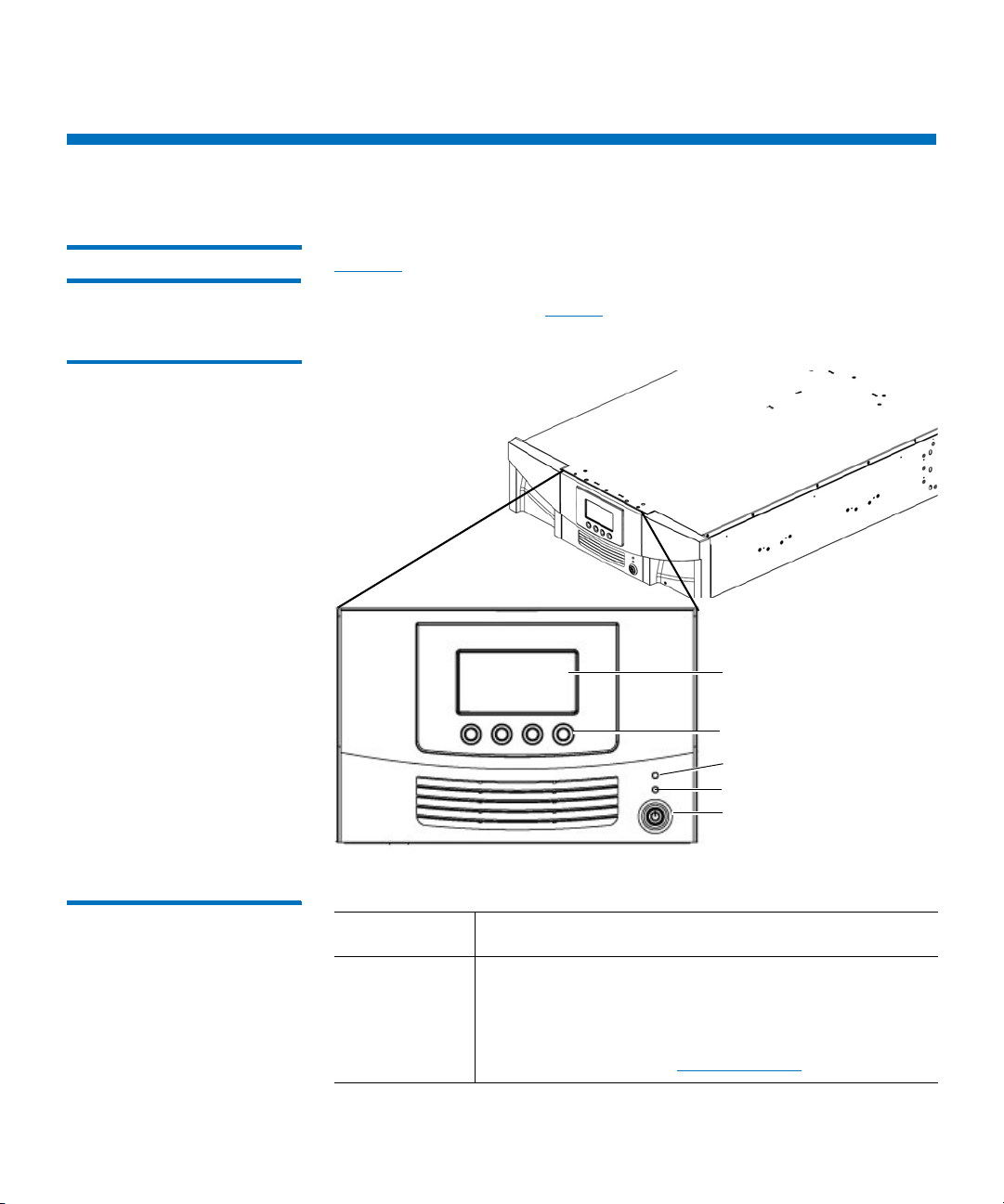
Operator panel screen
Ticket indicator LED
Power-on LED
Power button
Navigation/selection buttons
Library Components
Library Components
Front Panel Figure 1 illustrates the features of the operator panel. The picture shows
the Scalar i40, but the features are the same on the Scalar i80. These
features are described in
Figure 1 Front Panel
Ta bl e 1.
Table 1 Front Panel Features
Feature Description
Operator
panel screen
The operator panel displays library status
information and allows you to access the library
menus. These menus allow you to view or change
the library settings and run diagnostic tests. For
2 Quantum Scalar i40 and Scalar i80 User’s Guide
more information, see
Operator Panel on page 19.
Page 31

Feature Description
Chapter 1: Description
Library Components
Robotic System and Barcode Scanner
Four navigation/selection
buttons
These buttons, in combination with the operator
panel display, are used to scroll through screens and
select options or commands. The functionality of
these buttons changes depending on the currently
displayed operator panel screen.
Ticket indicator LED
Indicates whether a diagnostic ticket exists on the
library. See
Front Panel LEDs on page 257 and About
Diagnostic Tickets on page 248 for more informa-
tion.
Power-on LED Indicates whether library power is on or off. See
Front Panel LEDs on page 257 for more information.
Power button Turns the library on or off.
Turning off the library using the power button turns
off the robot and operator panel, but power still
runs to the power supplies. See
Shutting Down,
Restarting, Turning Off, and Removing Power on
page 139 for instructions on how to shut down the
library safely.
The robotic system identifies and moves the cartridges between the
storage slots, tape drives, and the I/E station. The robotic arm (picker)
has picker fingers that enable it to grab tape cartridges and move them
into and out of slots and tape drives.
A barcode scanner is attached to the library’s robotic hand. This barcode
scanner automatically identifies the slots and cartridges in the library, if
the cartridges are fitted with acceptable barcode labels.
Each tape cartridge must contain a unique, matching-readable barcode
that the barcode scanner reads during the inventory process. During the
inventory process, the barcode scanner reads the barcode labels on the
tape cartridges and empty slots to identify the types of tape cartridges
that are installed in the library.
Quantum Scalar i40 and Scalar i80 User’s Guide 3
Page 32

Chapter 1: Description
Library Components
Tape cartridges cannot have duplicate barcode labels. This barcode
identifies the cartridge. The library stores the physical location of the
tape cartridge in an inventory database. All library or host requests
typically reference the location of the tape cartridges based on this
barcode number. Barcode labels are mandatory and must adhere to
specific standards. For more information on barcodes, see
Chapter 11,
Working With Cartridges and Barcodes.
Robots can only be replaced by a Quantum Support technician.
Magazines Magazines are removable and contain storage and import/export
station slots for cartridges. Each magazine has 20 slots, arranged in four
columns of five slots each. The Scalar i40 contains two magazines; the
Scalar i80 contains four. The right magazines provide up to five slots
each for use as an import/export (I/E) station. For more information on
I/E stations, see Configuring I/E Station Slots on page 62.
Note: Cartridges are gently restrained within the magazine by a
detent found on the left side of each individual magazine bin
slot. To manually remove a cartridge, pull a cartridge from the
front or push on the cartridge from the rear of the magazine
via an “access hole.” Be gentle to avoid any bending of the top
magazine cover sheet metal.
The library will run if one or more magazines is open or removed;
however, it runs at reduced speed. The library will not move a cartridge
to an open or removed magazine, but it will move a cartridge to any of
the other installed magazines.
You can open the magazines using library software or manually. For
information, see
For information on removing and replacing magazines, see
Scalar i40 and Scalar i80: Magazine Replacement
4 Quantum Scalar i40 and Scalar i80 User’s Guide
Releasing Magazines on page 148.
6-66557-XX
.
Page 33

Chapter 1: Description
Library Components
Magazine Slot Location Coordinates
Each slot in the installed magazine is numbered with location
coordinates. The library location coordinate contains three digits as
follows: [Magazine],[Column],[Slot].
magazines and list all of the location coordinates.
• Magazine — Library magazine level is represented by the first digit
of a library coordinate. In a Scalar i40, there is only one level of
magazine. The coordinate is always zero. In a Scalar i80 library, the
bottom magazines are indicated by a zero; the top magazines are
indicated by the number
1.
• Column — A storage column is a group of slots arranged vertically
in the library. Columns are represented by the second digit of a
library coordinate. Columns are identified relative to the front left of
the library. The column in the front left of the library is number 1.
The column numbering continues around the library in a clockwise
direction. The I/E station column is always number 8.
• Slot — Slots (both storage and I/E station) are represented by the
third digit of the library location coordinate. Within each magazine
column, slots are numbered from 1 to 5, starting at the top of the
magazine.
Figure 2 and Figure 3 show the
Quantum Scalar i40 and Scalar i80 User’s Guide 5
Page 34

Chapter 1: Description
Left magazine
Right magazine
Robot on Y-tray
Ta p e Drives
Library Components
Figure 2 Scalar i40 Internal
Layout and Magazine Slot
Location Coordinates
Left Magazine Right Magazine
0,1,1 0,2,1 0,3,1 0,4,1 0,5,1 0,6,1 0,7,1 0,8,1
0,1,2 0,2,2 0,3,2 0,4,2 0,5,2 0,6,2 0,7,2 0,8,2
0,1,3 0,2,3 0,3,3 0,4,3 0,5,3 0,6,3 0,7,3 0,8,3
0,1,4 0,2,4 0,3,4 0,4,4 0,5,4 0,6,4 0,7,4 0,8,4
0,1,5 0,2,5 0,3,5 0,4,5 0,5,5 0,6,5 0,7,5 0,8,5
Front Back Front
6 Quantum Scalar i40 and Scalar i80 User’s Guide
Page 35
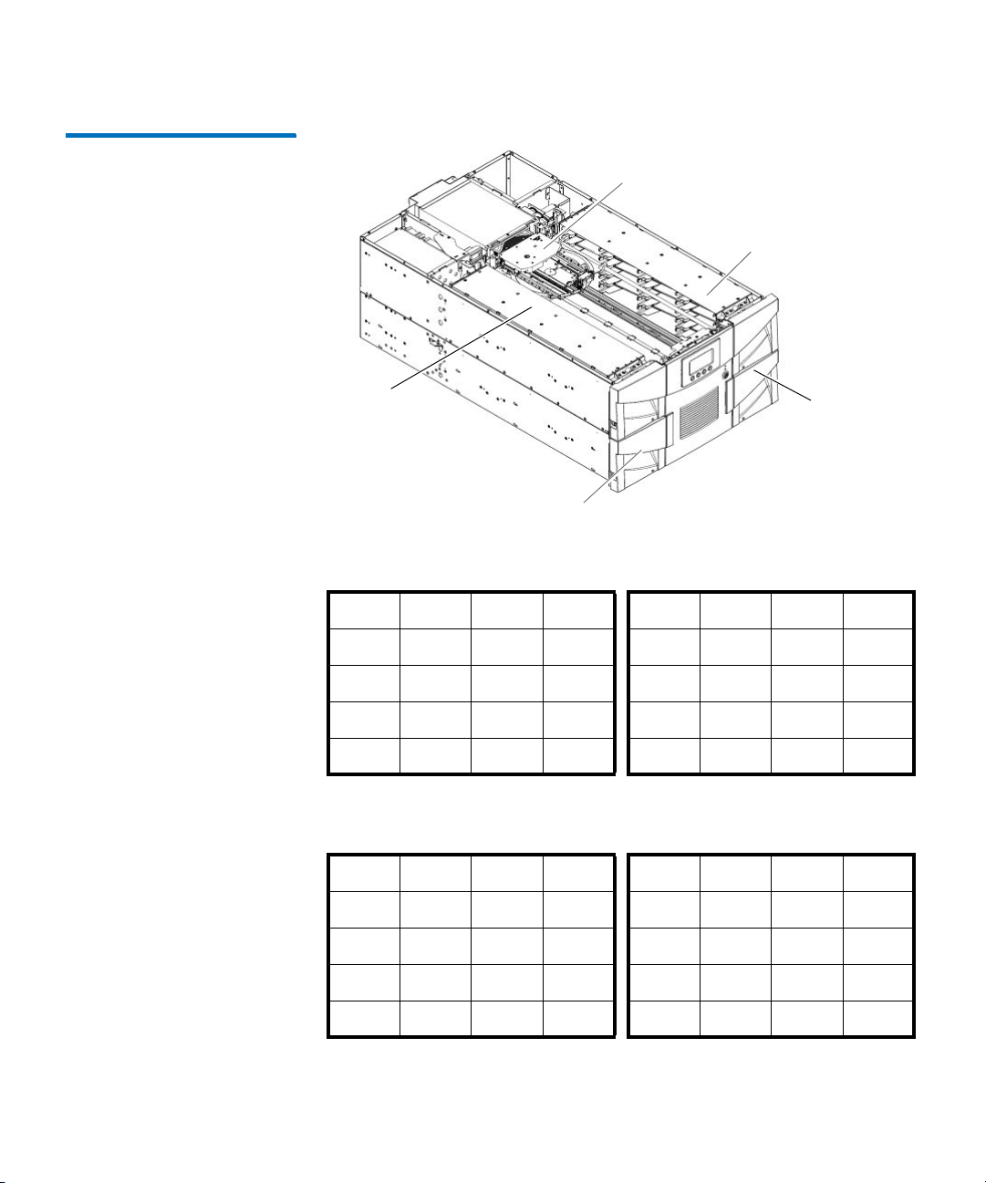
Figure 3 Scalar i80 Internal
Robot on Y-tray
Top lef t
magazine
Top righ t
magazine
Bottom left
magazine
Bottom right
magazine
Layout and Magazine Slot
Location Coordinates
Chapter 1: Description
Library Components
Top L e ft M a g az i n e Top Right Magazine
1,1,1 1,2,1 1,3,1 1,4,1 1,5,1 1,6,1 1,7,1 1,8,1
1,1,2 1,2,2 1,3,2 1,4,2 1,5,2 1,6,2 1,7,2 1,8,2
1,1,3 1,2,3 1,3,3 1,4,3 1,5,3 1,6,3 1,7,3 1,8,3
1,1,4 1,2,4 1,3,4 1,4,4 1,5,4 1,6,4 1,7,4 1,8,4
1,1,5 1,2,5 1,3,5 1,4,5 1,5,5 1,6,5 1,7,5 1,8,5
Front Back Front
Bottom Left Magazine Bottom Right Magazine
0,1,1 0,2,1 0,3,1 0,4,1 0,5,1 0,6,1 0,7,1 0,8,1
0,1,2 0,2,2 0,3,2 0,4,2 0,5,2 0,6,2 0,7,2 0,8,2
0,1,3 0,2,3 0,3,3 0,4,3 0,5,3 0,6,3 0,7,3 0,8,3
0,1,4 0,2,4 0,3,4 0,4,4 0,5,4 0,6,4 0,7,4 0,8,4
0,1,5 0,2,5 0,3,5 0,4,5 0,5,5 0,6,5 0,7,5 0,8,5
Quantum Scalar i40 and Scalar i80 User’s Guide 7
Front Back Front
Page 36

Chapter 1: Description
Library Components
Power Supply The Scalar i40 and Scalar i80 libraries support single power
configurations consisting of a single AC line input and single DC power
supply. The Scalar i80 library supports a redundant power configuration
consisting of a dual AC line input and dual DC power supplies.
If you have a Scalar i80 and are only using one power supply, the power
supply should be installed in the upper power supply slot, and a filler
plate must cover the empty power supply slot (see
If you are using redundant power, you can hot add or hot swap a power
supply (power to the library remains on while you add or exchange the
hardware).
The Scalar i40 power supply cannot be installed in a Scalar i80. However,
the Scalar i80 power supply works in either the Scalar i40 or the
Scalar
i80.
Warning: The power outlet must be available near the library and
must be easily accessible.
The power system consists of the following components:
Figure 5 on page 10).
• Power supply
• AC power cord
The power supply has one status LED. For more information, see Power
Supply LED on page 261.
For information on removing and replacing power supplies, see
66559-XX Scalar i40 and Scalar i80: Power Supply Replacement
.
System Control Board The system control board (SCB) contains the library firmware, all
configurable settings, license keys, and SKM TLS certificates. It manages
the entire library, including the operator panel and robot, and is
responsible for running system tests to ensure that the library is
functioning properly. The SCB has two Ethernet ports:
• Left port — For remote management (Web client)
• Right port — For service only. In rare cases, you may need to change
the IP address of the port if it conflicts with your library IP address
(see
Configuring the Service Port on page 78).
See Figure 4 on page 10 and Figure 5 on page 10 for port locations.
6-
8 Quantum Scalar i40 and Scalar i80 User’s Guide
Page 37

Chapter 1: Description
Library Components
The SCB contains one LED, in addition to two LEDs on each Ethernet
port (for a total of 5 LEDs). For more information, see
Board LEDs on page 259.
System Control
For information on removing and replacing the SCB, see
Scalar i40 and Scalar i80: System Control Board Replacement
6-66556-XX
.
Tape Drives Every library configuration must contain at least one tape drive.
See Appendix A, Specifications for a list of tape drives and media
supported by the Scalar i40 and Scalar i80 libraries.
The library supports mixing different tape drive types within the library
and within partitions. For information on how to do this, see
With Partitions on page 49.
Tape drives are installed into tape drive slots in the rear of the library. If a
tape drive slot is empty, a filler plate must cover the empty slot (see
Figure 5 on page 10).
Caution: Filler plates are required to maintain proper library cooling.
Do not run the library with uncovered slots.
SAS tape drives have one status LED. Fibre Channel tape drives contain a
status and a link LED. For more information on tape drive LEDs, see
Drive/Sled LEDs on page 260.
All tape drives contain only one cable connector.
Working
Ta pe
For information on removing and replacing tape drives, see
Scalar i40 and Scalar i80: Tape Drives Replacement
.
6-66561-XX
Installed Tape Drive Location Coordinates
Installed tape drives have a two-digit location coordinate. These are the
coordinates shown in the library configuration report. The first digit is
always zero. The second digit indicates the location of the tape drive
relative to the other tape drives. The bottommost tape drive has
location coordinates [0,1], the next-to-bottom has location coordinates
[0,2], and so on.
Quantum Scalar i40 and Scalar i80 User’s Guide 9
Page 38
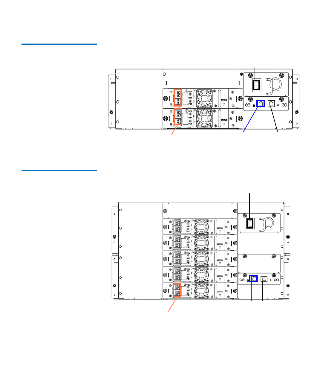
Chapter 1: Description
Half-height tape drives
Power supply cord
Service port –
do not use
Ethernet
cable in LEFT
SCB port
Tape drive cables
Half-height tape drives
Power supply cord
Power supply
filler plate
Service port –
do not use
Ethernet cable in
LEFT SCB port
Tape drive cables
Library Components
Figure 4 Scalar i40 Back Panel
Components
Figure 5 Scalar i80 Back Panel
Components
10 Quantum Scalar i40 and Scalar i80 User’s Guide
Page 39

Chapter 1: Description
Standard Features
Standard Features
This section describes several features of Scalar i40 and Scalar i80
libraries.
User Interface The operator panel is located on the front of the library and allows you
to work locally on the library via the user interface. The Web client
allows you to view and perform library functions from remote sites and
is accessible through a browser. The operator panel and Web client each
contain a different user interface and functionality.
See Chapter 3, Understanding the User Interface for more information
about the operator panel and the Web client.
Partitions Partitions are virtual sections within a library that present the
appearance of multiple, separate libraries for purposes of file
management, access by multiple users, or dedication to one or more
host applications.
Organizing the library into partitions divides the resources into virtual
sections. If one of the resources is not available due to a failure or other
cause, the other partitions and their assigned components are still
available. Partitions can also be used to control access to portions of the
library by granting permissions to user accounts to access certain
partitions (see
Accounts on the Web Client on page 81).
For more information on partitions, see Working With Partitions on
page 49.
Control Path Modification
Quantum Scalar i40 and Scalar i80 User’s Guide 11
The control path tape drive is used to connect a partition to a host
application. Only one tape drive can be selected as the control path at
one time. By default, the first tape drive assigned to a partition is
designated as the control path. In the event that the control path
connection to the host application fails, you can select a new control
path for the partition. See
Privilege Levels on page 80 and Creating Local User
Configuring Control Paths on page 66.
Page 40

Chapter 1: Description
Licensable Features
Support for WORM Scalar i40 and Scalar i80 tape libraries support WORM (write once, read
many) technology. WORM allows non-rewriteable and non-erasable
data to be written and provides extra data security by prohibiting
accidental data erasure. The WORM feature is supported whenever you
use WORM cartridges.
Licensable Features
In addition to the standard features, the following additional, licensable
features are available:
• Capacity on Demand (COD)
• Advanced Reporting - includes custom reports and logs and Control
Path Failover functionality.
• Encryption Key Management
For information on how to obtain and install a license key, see Adding or
Upgrading Licensable Features on page 68.
Capacity on Demand (COD)
12 Quantum Scalar i40 and Scalar i80 User’s Guide
All Scalar i40 and Scalar i80 library configurations ship with the
purchased number of slots pre-activated. After the initial purchase of
your library, you can activate any remaining inactive slots in your library
by purchasing a COD license upgrade.
• The Scalar i40 base configuration has 25 slots activated (these slots
comprise the first 5 magazine columns starting from the left front
magazine column going clockwise). You can buy a COD license to
activate the remaining 15 slots.
• The Scalar i80 base configuration has 50 slots activated (these slots
comprise the first 5 magazine columns starting from the left front
magazine column going clockwise). You can buy a COD license to
activate the remaining 30 slots.
To see your library’s current configuration and slot availability, open the
Library Configuration Report (choose
from the Web client).
Reports > Library Configuration
Page 41

Chapter 1: Description
Licensable Features
Advanced Reporting The Advanced Reporting license applies to your entire library, regardless
of library size. This means you only need to purchase the license once. If
you increase the size of your library, your existing license applies to your
new library configuration.
Advanced Reporting provides the following features and reports that
you can configure for viewing and analysis:
Control Path Failover (CPF) - Provides support for configuring the
LTO-5 or LTO-6 drive for control path failover. When control path failover
is used, one drive is assigned as the primary control path and another
drive as the control path failover (secondary) drive. The control path
failover drive is used whenever the primary control path drive fails or is
inoperable
Reports - Listed below are report names. You can view, configure, send
via e-mail, and save and reuse report configurations as templates. In
addition, you can automatically e-mail any of the reports to designated
recipients at specified, scheduled times.
• Drive Resource Utilization Report—Provides tape drive usage
information, showing you which tape drives are working at
optimum capacity and which are under-utilized. This can help you
allocate your tape drive resources properly.
• Media Integrity Analysis Report—Provides Tape Alert count for
various combinations of tape drives, tape cartridges, and Tape Alert
flags. This can help you determine if a problem is due to a specific
tape drive or tape cartridge.
Logs - Listed below are available logs:
• Media Security Log - Lists media that has been removed from the
library.
• Media Usage Log - Lists information on all media that have ever been
in the library.
For information on how to use the advanced reporting features, see
Advanced Reporting on page 111.
Quantum Scalar i40 and Scalar i80 User’s Guide 13
Page 42

Chapter 1: Description
Licensable Features
Encryption Key Management
The Encryption Key Management (EKM) license enables tape drive
transparent encryption using library-managed encryption. The EKM
license applies to the entire library, regardless of how many slots are
licensed. If you increase the number of slots in your library, your existing
license applies to your new library configuration. For more information
about EKM, see
Chapter 7, Encryption Key Management.
14 Quantum Scalar i40 and Scalar i80 User’s Guide
Page 43

Chapter 2
Unpacking the Library
Choose a location in which to install the library that is as free from dust
as possible. Dust can damage or degrade performance of library
components and media.
Refer to the following sections of this manual for important information
that you need when installing and setting up your library:
• Environmental Specifications on page 279
• Taking ESD Precautions on page xxiii
Note: Unpack the library as close to the installation location as
possible.
1 Inspect the outer library packaging for damage. If there is any
damage evident on the library packaging, do not continue with the
installation and contact Quantum customer support.
2 Open the library packing box and remove the kit tray containing the
accessory kit and the rail kit (see
come with tape drives installed in the library, and some come with
tape drives packaged separately. If yours comes with tape drives
packaged separately, remove them and set aside for installation
later.
Quantum Scalar i40 and Scalar i80 User’s Guide 15
Figure 6). Some configurations
Page 44

Chapter 2: Unpacking the Library
Kit tray
Accessory kit
Bottom foam
Shipping carton
Rail kit
Media labels
Bottom tray (Scalar i80 only)
Pallet (Scalar i80 only)
Scalar i80
Scalar i40
To p foam
Figure 6 Packaging
3 Remove the top foam.
4 Scalar i80 only: Remove the shipping carton by lifting it straight up
out of the bottom tray.
5 With the help of a second person, lift the library chassis out of the
shipping carton and place it on a table approximately waist high.
16 Quantum Scalar i40 and Scalar i80 User’s Guide
Page 45

Chapter 2: Unpacking the Library
WARNING: Two people are required to safely lift the library out of
its packaging or into a rack.
Caution: Lift the library chassis at the sides. Avoid putting the
weight of the library chassis on the front bezel.
6 Remove the anti-static wrapping from the library. Keep the anti-
static wrapping intact so that you can use it later if needed.
7 Save the packing box, packaging material, and anti-static wrapping
in case you need to move or ship the library in the future.
8 Remove the Y-tray restraint. The Y-tray restraint consists of four (4)
thumbscrews, a plastic sheet, a small metal clip, and underneath
the plastic sheet, an orange restraint tab—located on the top cover
of the library. See
Figure 7.
a Unscrew and remove the four thumbscrews from the top cover
(see
Figure 7). Save the thumbscrews in case you need to move
or ship the library in the future.
b Remove the plastic sheet and metal clip and discard. You will
not need to use them again.
Caution: Remove the orange shipping restraint tab and discard.
You will not need to use it again.
Quantum Scalar i40 and Scalar i80 User’s Guide 17
Page 46

Chapter 2: Unpacking the Library
Figure 7 Removing the Robot
Restraint
Note: The Y-tray may stay at the top of the library, or it may
move downward toward the floor of the library. If it
moves downward, you will hear the gears turning as it
moves. This is normal.
9 Once you remove the Y-tray restraint, you may cover the holes in the
library top cover with stickers, which are provided in the accessory
kit for this purpose. This step is optional and is intended to prevent
small objects from accidentally falling into the library through the
holes.
10 Remove the protective plastic sheet covering the front panel display.
18 Quantum Scalar i40 and Scalar i80 User’s Guide
Page 47

Chapter 3
Understanding the User
Interface
The user interface for the Scalar i40 and Scalar i80 libraries is available in
two formats: the operator panel and the Web client. Operations on the
library can be performed locally on the operator panel or remotely on
your computer using the Web client.
Both the operator panel and the Web client are required to operate the
library. Some functionality is only available through the Web client, and
some functionality is only available through the operator panel.
However, it is recommended that you use the Web client rather than the
operator panel to perform most library operations.
This chapter covers:
• Operator Panel
• Web Client
• Menu Trees
Operator Panel
The operator panel is located on the front panel of the physical library.
The operator panel screen contains a menu bar with operations that
correspond to the four physical buttons below it. The menu operations
and button functions change with each screen.
Quantum Scalar i40 and Scalar i80 User’s Guide 19
Page 48

Chapter 3: Understanding the User Interface
Title bar
Menu bar
Navigation/selection
buttons
Name
Status Health status
Active display
Operator Panel
The operator panel home screen refreshes every 5 seconds to provide
up-to-date information about library performance.
Operator Panel Layout and Functions
Figure 8 Operator Panel User
Interface - Home Screen
You can choose your desired operator panel home screen that displays
on the local user interface—the default home screen or the alternate
home screen that allows easy I/E unlock access.
Figure 8 and Figure 9
depict these screen options; Tabl e 2 describes the operator panel
functions.
You can choose to change the view of the home screen for easy I/E
unlock access. Refer to
Changing Operator Panel Home Screen View on
page 108.
20 Quantum Scalar i40 and Scalar i80 User’s Guide
Page 49
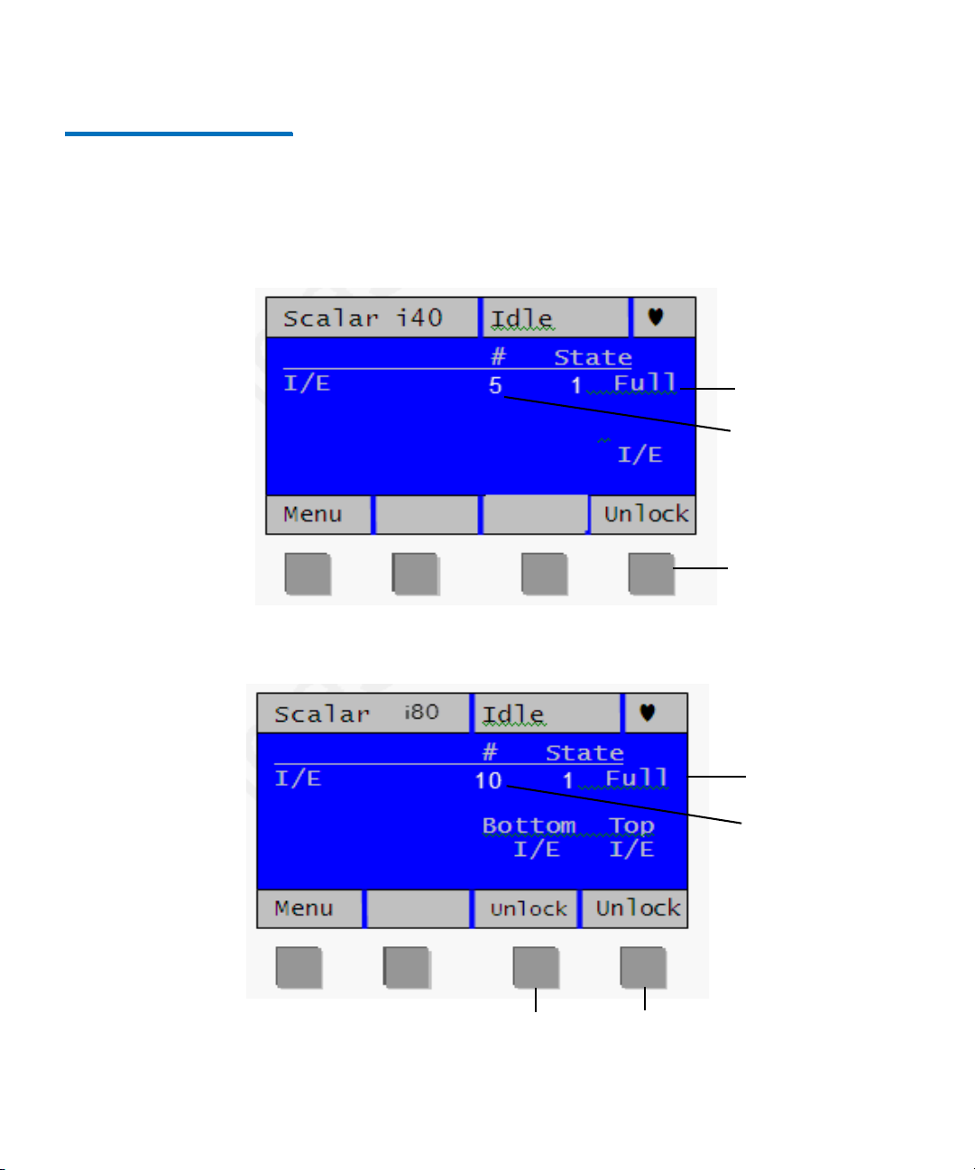
Figure 9 Operator Panel User
Number of configured
I /E slots
Number of occupied
I /E slots
Scalar i40
Scalar i80
Number of occupied
I /E slots
Number of
configured I/E slots
Unlock I/E Station
Unlock bottom
I/E Station
Unlock top
I/E Station
Interface - Alternate Home
Screen
Chapter 3: Understanding the User Interface
Operator Panel
Quantum Scalar i40 and Scalar i80 User’s Guide 21
Page 50

Chapter 3: Understanding the User Interface
Operator Panel
Table 2 Operator Panel
Functions
Operator Panel
Element
Description
Title bar The title bar is present on every screen, and
contains three fields: name, status, and health
status.
Name The name field displays a description of the
current view. It changes depending on the menu
selection.
• On the home screen, the field displays the
library type (Scalar i40 or Scalar i80).
• On active pages, the field displays the name of
the main menu (Setup, Actions, Tools, Reports).
• When a message displays, the field displays the
message type (Success, Completed,
Information, FAILURE, NOTICE). Failure
messages will blink.
22 Quantum Scalar i40 and Scalar i80 User’s Guide
Page 51

Chapter 3: Understanding the User Interface
Operator Panel
Operator Panel
Element Description
Status The status field displays the current state or
operation being performed by the robot. If the
robot is not idle, the status will blink. Status can
be any of the following:
• Initializing — The library is currently in the
process of initializing.
• Autoleveling — The robotics hardware is being
autoleveled.
• Homing — The robot is performing a home
operation.
• Teaching — The robot is performing a teach
operation.
• Calibrating — The robot is performing a
calibration operation.
• Scanning — The robot is performing an
inventory operation.
• Unlocking — The robot is in the process of
unlocking a magazine.
• Move Media — The robot is moving media
from one location to another.
• Loading — The robot is in the process of
moving a tape to load into a tape drive.
• Unloading — The robot is in the process of
unloading a tape drive and returning it to the
source location.
• Idle — The robot is ready and idle.
• Not Ready — The robotics system is not ready.
Quantum Scalar i40 and Scalar i80 User’s Guide 23
Page 52

Chapter 3: Understanding the User Interface
Operator Panel
Operator Panel
Element Description
Health status The health status field displays an icon
Active display The active display provides information or menu
representing the health of the library.
Heart — Library is in good health (no open
or unopened diagnostic tickets are present).
Trian gle — Library health is degraded
(library contains open or unopened low- or
high-priority diagnostic tickets).
Exclamation point — Immediate attention
is required (library contains open or
unopened urgent diagnostic tickets).
items according to the selected menu item or
operation.
The default home screen displays the number and
state of partitions, tape drives, storage slots, and
I/E slots.
The alternate home screen displays the number
and state of the I/E slots, and provides access to
unlock I/E stations.
Menu bar The menu bar displays the function associated
with each of the navigation/selection buttons.
The button function changes with each menu.
Common functions are navigation (up, down,
left, right, next) and menu selection (select, apply,
exit, yes, no, cancel).
Navigation/
Selection
Buttons
The physical buttons enable you to navigate
menus and start and stop library operations
according to the functions listed in the button
bar. Not all buttons are functional for every
operation. See
Navigating and Editing on the
Operator Panel on page 25 for more information.
24 Quantum Scalar i40 and Scalar i80 User’s Guide
Page 53

Chapter 3: Understanding the User Interface
Operator Panel
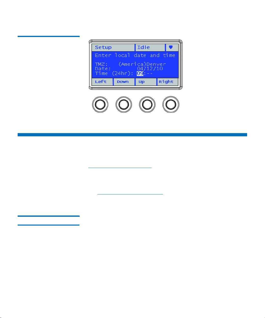
Navigating and Editing on the Operator Panel
You use the four navigation/selection buttons exclusively to move
through the menus and commands on the operator panel.
From the default home screen, the menu bar lists the four main menu
headings. From the alternate home screen, you can select Menu to
return to the default home screen to access the four main menu
headings.
Press the button corresponding to a menu item to bring up the list of
sub-menu items. The item you are currently on is highlighted. Press the
buttons corresponding to Up, Down, Left, or Right to navigate to a
desired menu item. As you move through the items, the highlighting
moves with you so you always know which item you are on. Press the
button corresponding to Select to select a highlighted item or action.
This in turn brings up either another sub-menu, a screen where you can
modify settings or perform operations, or a screen displaying
information.
To edit a modifiable field, such as date, time, licenses, IP address, and so
on, use the Left and Right buttons to move through the field, one
segment at a time (for license keys and passwords, you will move one
digit or letter at a time). Use the Up and Down buttons to change the
value of each segment. When you reach the value you want, press the
Right button. As you press Right, the value fills in and you go to the
next segment. To edit a previous entry, press the Left button until you
reach the entry and edit as before. For multiple fields, continue to press
Right after each entry until you reach the last entry. At this point, the
Right button designation changes to Apply. Press the Apply button.
The new information displays. Press Exit to exit. For an example, see
Figure 10 on page 26.
To scroll through a list of items, or to edit letters and numbers, you can
press the appropriate button repeatedly to scroll one item at a time, or
you can hold the button down for fast scrolling through the available
options.
To exit a screen, press the Exit button.
To cancel an operation without saving any changes, press the Cancel
button. If you are in the middle of making changes, repeatedly press the
Left button until you are back at the first field on the screen, then press
the Cancel button.
Quantum Scalar i40 and Scalar i80 User’s Guide 25
Page 54
Chapter 3: Understanding the User Interface
Web Client
Figure 10 Using the Buttons to
Set the Date and Time
Web Client
The Web client interface is accessible from supported Web browsers (see
Supported Internet Browsers on page 283).
To access the library from a remote location, the library must be
connected to your network via an Ethernet connection. Simply enter the
library’s IP address in your Internet browser bar to access the Web client.
See
Configuring Network Settings on page 38 for information on
setting the network configuration settings for remote use.
Tips Keep the following tips in mind when using the Web client:
• You must disable Web browser popup blockers to use the Web
client interface and the library’s online Help. Add the Scalar i40 or
Scalar i80’s Internet Protocol (IP) address to the list of trusted/
allowed sites on your Scalar i40- or Scalar i80-supported browser, so
the Web client pages will automatically refresh.
• Do not use your Internet browser Back button to navigate the Web
client pages. Instead, use the buttons provided within the Web
client.
26 Quantum Scalar i40 and Scalar i80 User’s Guide
Page 55

Chapter 3: Understanding the User Interface
Web Client
• Optimum screen resolution for viewing using a Windows operating
system is 96 DPI. If your resolution is set higher, certain screen
messages may not display as intended. To change screen resolution,
show the desktop, right click to display the Properties window, and
click Settings > Advanced.
• Log out of the library before closing the Internet browser window
when you are using the Web client. If you do not log out, the
session will remain open. Clicking the close button (
right corner of the Web client closes the browser window but does
not log you out.
X) in the upper-
Sorting Information in Ta bl es
Web Client Layout and Functions
You can sort information displayed in tables if the table column heading
is bold. Click the column heading and the information will sort. Click
again to toggle from ascending to descending.
Figure 11 on page 28 shows the Web client interface. Table 3 on
page 29 explains the Web client interface elements.
Quantum Scalar i40 and Scalar i80 User’s Guide 27
Page 56
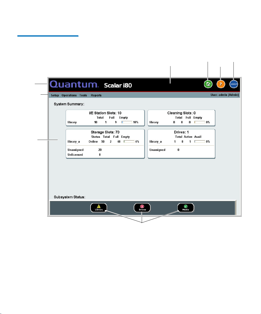
Chapter 3: Understanding the User Interface
Header
Menu bar
Active
display
Online
help
Logout
Home
View diagnostic tickets
“Library is not ready”
message area
Web Client
Figure 11 Web Client User
Interface - Home Page
28 Quantum Scalar i40 and Scalar i80 User’s Guide
Page 57
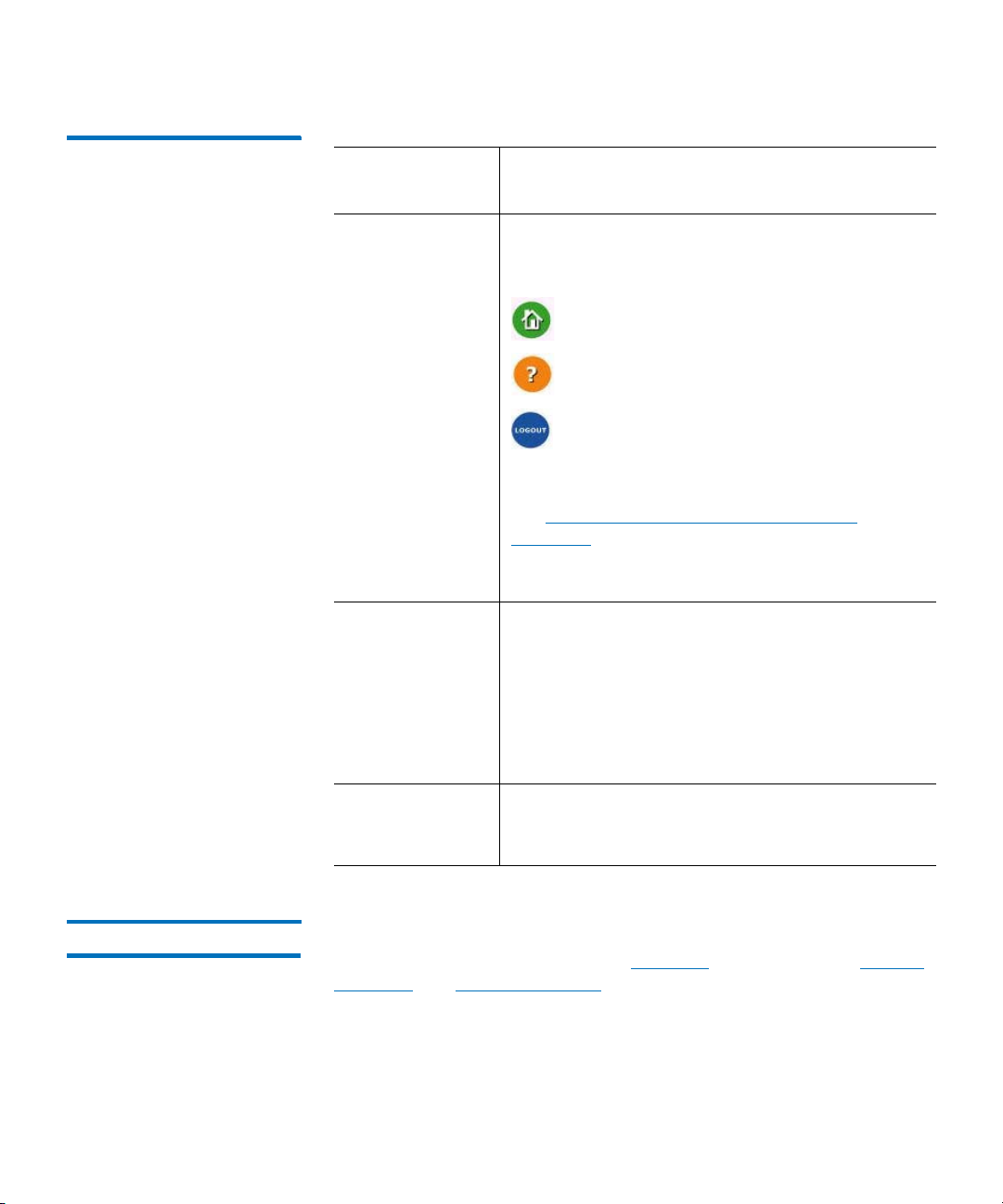
Chapter 3: Understanding the User Interface
Web Client
Table 3 Web Client Screen
Elements
Web Client
Element
Description
Header The header is present on all pages and contains
the library type (Scalar i40 or Scalar i80) and three
buttons:
Home — Brings you to the home page.
Help — Displays the online help.
Logout — Logs out of the current session.
A message in the header alerts you when the
robot is not ready to perform library functions.
See
Troubleshooting Library “Not Ready”
Messages on page 254 for more information on
“Library Not Ready” messages displayed in the
header.
Menu bar Displays the available menu choices. The choices
vary depending on login privileges.
The far right of the menu bar also displays the
name of the logged-in user, with the associated
privilege level indicated in brackets.
If a menu item selected has a sub-menu, then >
is displayed to the right of the item.
Active display The active display provides information or menu
items according to the selected menu item or
operation.
Web Client Home Page The home page displays status and health information in the active
display portion of the window (see
Summary and Subsystem Status below for more information.
Quantum Scalar i40 and Scalar i80 User’s Guide 29
Figure 11 on page 28). See System
Page 58

Chapter 3: Understanding the User Interface
Web Client
System Summary The system summary is available on the home page of the Web client.
It provides tabular data on the capacity of the library’s partitions, slots,
and tape drives. It also displays whether partitions are online or offline
(in the Storage Slots section). The current user’s login privileges
determine which partitions are displayed (see
Privilege Levels on
page 80).
Subsystem Status You can quickly gauge the health of the library by observing the color of
the three subsystem status buttons located at the bottom of the home
page. These buttons provide quick access to information about the
“health” of the library for faster recovery if problems occur. You can
select the buttons to view diagnostic tickets that report problems in the
subsystems.
The three subsystems are:
• Library — Represents connectivity, control, cooling, power, and
robotics.
• Drives — Represents tape drive components, such as tape drives,
tape drive firmware, and tape drive sleds.
• Media — Represents media components, such as cartridges and
barcode labels.
Each button has three states indicated by color. The three states are:
Green (check mark) — No diagnostic tickets exist, or, if any tickets
do exist, they have all been closed.
Yellow (exclamation point) — The library contains open or
unopened, low- or high-priority diagnostic tickets.
Red (“X” mark) — The library contains open or unopened urgent
diagnostic tickets.
If the color of a subsystem button is red or yellow, you can click the
button to display the corresponding
Diagnostic Tickets screen. This
screen lists library, drives, or media tickets, depending on which button
was selected. See
About Diagnostic Tickets on page 248 for more
information.
30 Quantum Scalar i40 and Scalar i80 User’s Guide
Page 59

Menu Trees
Chapter 3: Understanding the User Interface
Menu Trees
The following menus organize operations and commands into logical
groupings:
•The Setup menu consists of commands that users with
administrator privileges can use to set up and configure various
aspects of the library, including partitions, I/E station slots, cleaning
slots, control paths, network settings, drive settings, users,
notifications, date and time, licenses, library registration, and email.
•The Operations/Actions menu consists of commands that enable
users to change the library’s mode of operations, import and export
cartridges, load and unload tape drives, move media, lock or unlock
the I/E station, log out, and shut the library down. The menu is
called Actions on the operator panel and Operations on the Web
client.
•The Too ls menu consists of commands that you can use to maintain
your library such as viewing diagnostic tickets, generating
diagnostic logs, identifying drives, configuring the internal network,
saving and restoring the library configuration, setting system and
security settings, and updating firmware, and performing library
diagnostics.
•The Reports menu provides various kinds of library information.
Administrators have access to all menu commands, but users’ privileges
are more limited.
Figure 12 lists the operator panel menus. Figure 13 lists the Web client
menus.
Quantum Scalar i40 and Scalar i80 User’s Guide 31
Page 60

Chapter 3: Understanding the User Interface
Setup
Network Configuration
Date & Time
License Installation
Dedicated Slots
Tape Drives (FC)
Configure Partitions
Account Settings
Security Services
Actions
Import Cleaning Tape
Unlock I/E Station
Magazine
Release
Tape Drive
Unload
Change Mode
Manual Cleaning
Reset
Shutdown
Tools
IVT
Diagnostics
Random Move Test
Service Network
Reset Factory Defaults
Reports
Diagnostic Tickets
About Library
Partitions
Network Settings
Date/Time
Licenses
Copyright Statement
Admin Privileges Only
All Users
ACCESS KEY
Operator Panel
Main Menu Bar
I/E
Import Tape
Export Tape
Export Cleaning Tape
Robotics Test
Tape Drive Test
Magazine Test
Library
Tape Drives
Media
Password Settings
Session Timeout
Modify Password*
* Only Available if LUI
Passwords are enabled
NOTE: If passwords are not
enabled on the operator
panel, all users have access
to all menus and functions.
Cleaning
I/E
Network IF
SSH Services
ICMP
Web client
Service User
SNMP V1/V2
SSL
Unload Assist
System Settings
Logical SN Addr
Man Cart Assign
SNMP
SMI-S
Shutdown Library
Restart Library
View Current
Partitions
Auto-Create Partitions
Delete Partitions
Power Save
Modify Subnet
Close ALL
Tape Drives
Robotics View
Change Partition Mode
Alternate Home
Auto DT Close
Menu Trees
Figure 12 Operator Panel
Menus
32 Quantum Scalar i40 and Scalar i80 User’s Guide
Page 61

Figure 13 Web Client Menus
Setup
Setup Wizard
Partitions
Cleaning Slots
I/E Station Slots
Advanced Reporting
E-mail Configuration
Drive Settings
Control Path
License
Notification
Diagnostic Tickets
Network Management
Network
SNMP
SNMP Trap
Registrations
User Management
User Accounts
Remote Authentication
Reset Operator Panel
Passwords
3YSTEM3ETTINGS
$ATE4IME
Operations
Media
Import
Move
Export
Cleaning Media
Export
Import
Partitions
Change Mode
Drive
Unload
Load
Change Mode
I/E Station ,OCKUnlock
Release Magazines
System Shutdown
Tools
All Diagnostic Tickets
Capture Snapshot
Save/Restore
Configuration
E-mail Configuration
Record
Save Configuration Record
Drive Operations
Download SNMP MIB
Update Library Firmware
Diagnostics
Reports
System Information
Library Configuration
Network Settings
Logged In Users
All Slots
Log Viewer
Advanced Reporting
Drive Resource
Utilization
Media Integrity Analysis
About
Scalar i40/i80
Open Source Licenses
Log Out
Admin Privileges Only
All Users
ACCESS KEY
Web Client
Main Menu Bar
Encryption
System Configuration
Partition Configuration
EKM Management
Encryption Certificate
Import Communication
Certificates
Encryption Key
Retrieve SKM Logs
Import
Export
Import
Export
Receiver
Addresses
Media Security
Receiver
Addresses
Contact
Information
EKM Path Diagnostics
3ERVER3TATUS
!UDIT,OG
Chapter 3: Understanding the User Interface
Menu Trees
Quantum Scalar i40 and Scalar i80 User’s Guide 33
Page 62

Chapter 3: Understanding the User Interface
Menu Trees
34 Quantum Scalar i40 and Scalar i80 User’s Guide
Page 63

Chapter 4
Configuring the Library
A Setup Wizard is available to assist you with the initial configuration of
the library. The Setup Wizard, however, contains only a subset of
configuration tasks. The operator panel and Web client menus provide
access to all configuration options that are included in the Setup Wizard
and many that are not.
This chapter covers the Setup Wizard and all of the other configuration
options. Paths to open the appropriate screens on both the operator
panel and the Web client are given for each task. (For complete menu
trees, see
Note: These operations should not be performed concurrently by
Menu Trees on page 31.)
multiple administrators logged in from different locations. You
can access the screens, but you cannot apply changes while
another administrator is performing the same operation.
Caution: Always save the library configuration after modifying a
configurable item. This will allow you to restore the most
current settings if necessary. See
Library Configuration on page 106.
Note: Power cycling (powering the library on and off) is not necessary
to configure the library.
Quantum Scalar i40 and Scalar i80 User’s Guide 35
Saving and Restoring the
Page 64

Chapter 4: Configuring the Library
This chapter covers:
• Using the Setup Wizard
• Configuring Network Settings
• Configuring SNMP Settings
• Setting the Date, Time, and Time Zone
• Working With Partitions
• Configuring Cleaning Slots
• Configuring I/E Station Slots
• Configuring Tape Drive Parameters
• Configuring Control Paths
• Adding or Upgrading Licensable Features
• Working With E-mail Notifications
• Configuring the Library E-Mail Account
• Setting Customer Contact Information
• Configuring the Service Port
• Working With Local User Accounts and Passwords
• Working With LDAP User Accounts (Remote Authentication)
• Setting the Session Timeout
• Configuring System Settings
• Configuring Security Settings
• Saving and Restoring the Library Configuration
• Registering the Library
• Changing Operator Panel Home Screen View
36 Quantum Scalar i40 and Scalar i80 User’s Guide
Page 65

Using the Setup Wizard
Chapter 4: Configuring the Library
Using the Setup Wizard
WARNING: Follow all setup and cabling instructions in the
and Scalar i80 Quick Start Guide
Wizard.
When you first power on the library, the operator panel displays the
Setup Wizard, which walks you through the initial configuration of the
library’s basic operational settings.
Note: Library initialization can take approximately 9 to 23 minutes for
an i40, or 14 to 40 minutes for an i80.
library during initialization.
The Setup Wizard on the operator panel displays when you first install
your library. It displays only once, with the following exceptions: it will
also display after SCB replacement, resetting factory defaults, or
downgrading library firmware.
When the Setup Wizard displays on the operator panel, you must either
complete the Setup Wizard or cancel out of it. If you cancel, you accept
the library’s default configuration (see
page 38). You can modify the configuration at any time later using the
Setup Wizard on the Web client, or by using the Setup menu options
from the operator panel or Web client.
Default Configuration on
before using the Setup
Do not
interrupt the
Scalar i40
Operator Panel
The Setup Wizard on the operator panel is covered in detail in the
Scalar i40 and Scalar i80 Quick Start Guide
.
Web Client
To access the Setup Wizard, click Setup > Setup Wizard. Work through
several screens that enable you to add licenses; set date, time, and time
zone; configure cleaning slots; configure I/E station slots; and autocreate partitions.
Quantum Scalar i40 and Scalar i80 User’s Guide 37
Page 66

Chapter 4: Configuring the Library
Default Configuration
Default Configuration
The library comes with a default configuration, which you can modify at
any time. The default configuration is as follows:
Feature Default Configuration
Library host name library
Network settings IPv4, DHCP enabled
Number of partitions Equal to the number of unique tape
IPv6 disabled
drives — based on interface type (Fibre
Channel or SAS) and drive generation
(LTO-4, LTO-5, LTO-6) — not currently
assigned to a partition.
Storage slots are divided equally
among the partitions.
Number of I/E station slots 5
Number of cleaning slots 0
Configuring Network Settings
The operator panel Setup Wizard allows you to configure network
settings that allow remote access to the library from the Web client. At a
minimum, you must initially configure the network IP address from the
operator panel. After the initial configuration, you can modify the
network settings from either the operator panel or the Web client.
38 Quantum Scalar i40 and Scalar i80 User’s Guide
Page 67

Chapter 4: Configuring the Library
Configuring Network Settings
Note: Changing the network settings may interrupt the library
connection and library communication. Your current browser
session may become invalid. If this happens, you must close
your browser and then restart it to reconnect to the library with
your new configuration settings.
Note: Make sure that the library is connected to the network before
modifying network settings. If the Ethernet cable is not
installed properly, you cannot configure the network settings.
Install one end of the Ethernet cable in the left-most Ethernet
port of the system control board (SCB) located on the back of
the library (see
Figure 4 or Figure 5 on page 10). Make sure the
other end of the Ethernet cable is installed in the appropriate
LAN port on your LAN.
You can configure the following network settings:
• Library Host Name
• DHCP
• IP Addresses
• Default Gateway, Subnet Mask, Network Prefix, and DNS Addresses
Some settings are only available on the Web client; others are only
available on the operator panel, as described below.
Library Host Name The host name is the network name you want to assign to the library.
The host name is limited to 12 lowercase alphanumeric characters and
dashes (-).
You can view, but not modify, the host name on the operator panel. To
modify the host name, you must use the Web client.
Web Client
1 Select Setup > Network Management > Network.
2 Type a name in the Host Name field, and click Apply.
Quantum Scalar i40 and Scalar i80 User’s Guide 39
Page 68

Chapter 4: Configuring the Library
Configuring Network Settings
DHCP DHCP is enabled by default. When DHCP is enabled, the library obtains
an IP address automatically. If DHCP is disabled, you must manually
enter an IP address, default gateway, and subnet mask/net prefix. You
can enable/disable DHCP from the operator panel or Web client.
Operator Panel
Select Setup > Network Configuration.
Web Client
Select Setup > Network Management > Network.
IP Addresses The library can support both IPv4 and IPv6 network settings at the same
time. For more details, see the bullets below.
Caution: If you change the IP address on your library, make sure to
change it on any host applications that access the library.
Note: Be sure to add your library’s IP address to the list of trusted/
allowed sites on your library-supported browser, so the Web
client pages automatically refresh.
• IPv4 Addresses — The library always supports IPv4 network
settings. The library can support either a DHCP-obtained or a static
IPv4 address.
IPv4 addresses must be entered in dot notation (for example,
192.168.0.1). They are limited to numeric characters and do not
allow values exceeding 255 for dot-separated values.
• IPv6 Addresses — IPv6 is disabled by default and can only be
enabled/disabled via the operator panel. Once enabled, you must
use the Web client to modify the address. Unlike IPv4, the library
can support both DHCP-obtained and static IPv6 addresses at the
same time.
40 Quantum Scalar i40 and Scalar i80 User’s Guide
Page 69

Chapter 4: Configuring the Library
Configuring Network Settings
IPv6 addresses must be entered in the proper notation. IPv6 address
can be entered in the most common notation, as eight groups of
four hexadecimal digits. 2001:0ff8:55cc:033b:1319:8a2e:01de:1374
is an example of a valid IPv6 address. Also, if one or more of the
four-digit groups contains 0000, you can omit the zeros and replace
them with two colons (::), as long as there is only one double colon
used in an address. Using this notation,
2001:0ff8:0000:0000:0000:0000:01de:1374 is the same as
2001:0ff8::01de:1374.
You can configure IPv4 addresses on the operator panel or Web client.
You can set the library to use IPv6 via the operator panel, but you must
use the Web client to configure a static IPv6 address.
Operator Panel
1 Select Setup > Network Configuration.
2 Modify the IP address using the method described in Navigating
and Editing on the Operator Panel on page 25.
Web Client
Select Setup > Network Management > Network.
Default Gateway, Subnet Mask, Network Prefix, and DNS Addresses
Quantum Scalar i40 and Scalar i80 User’s Guide 41
These settings have specific configuration requirements, as follows:
• Default Gateway — The IP address of the default gateway for your
portion of the Ethernet network. For IPv4, this setting can only be
changed if DHCP is disabled.
• Subnet Mask (IPv4 only) — Available only if DHCP is disabled.
• Network Prefix (IPv6 only). Can be entered only on the Web client.
• Primary DNS Address (optional, Web client only) — Must be entered
as an IP address. This text box is available only if DHCP is disabled.
• Secondary DNS Address (optional, Web client only) — Must be
entered as an IP address. This text box is available only if DHCP is
disabled.
Page 70

Chapter 4: Configuring the Library
Configuring SNMP Settings
Operator Panel
1 Select Setup > Network Configuration.
2 Modify the fields using the method described in Navigating and
Editing on the Operator Panel on page 25.
Web Client
Select Setup > Network Management > Network.
Configuring SNMP Settings
Simple Network Management Protocol (SNMP) is a light-weight
protocol designed for remote management and monitoring of
infrastructure devices. The library provides SNMP support, so an external
management application can be configured to receive library SNMP
information. The library supports SNMP by publishing a Management
Information Base (MIB) that can be queried to obtain the status of the
library and many of its individual components. SNMP information can
be obtained from the library using SNMP Traps and GET queries.
For more information about SNMP, see the
Basic SNMP Reference Guide
For information on integrating MIBs with an SNMP management
application, contact your network management application vendor.
Registering External Management Applications
42 Quantum Scalar i40 and Scalar i80 User’s Guide
Administrators can register transport protocols, IP addresses, and port
numbers of external management applications to enable them to
receive SNMP traps from the library. (By default, the library ignores all
SNMP SET operations, so external management applications cannot
register themselves to receive SNMP traps from the library.)
After registering the transport protocols, IP addresses, and
corresponding port numbers, you can perform a test to verify that the
library can send the SNMP traps to the addresses.
(6-66773-xx).
Scalar i40 and Scalar i80
Page 71

Chapter 4: Configuring the Library
Configuring SNMP Settings
When registering external management applications to receive SNMP
traps, you can set the following parameters:
• Transport — The transport protocol. This should be the same as the
transport protocol configured on the SNMP trap receiver. Select one
of the following:
• UDP — User Datagram Protocol for IPv4.
• UDP6 — User Datagram Protocol for IPv6.
• TCP — Transmission Control Protocol for IPv4.
• TCP6 — Transmission Control Protocol for IPv6.
• Host Name/IP Address — The host name or the IP address of the
external management application you want to register. A host name
may be entered only if DNS is enabled. Otherwise, IP addresses must
entered. For information on DNS, see
Default Gateway, Subnet
Mask, Network Prefix, and DNS Addresses on page 41.
• Port — the port number of the external application you want to
register. The default port number for an external application is 162.
You can only perform these functions from the Web client.
Web Client
1 Select Setup > Network Management > SNMP Trap
Registrations.
2 Click one of the following buttons to perform these actions:
• Create — Adds the IP address and port number of the external
application to the list of registered addresses that will be sent
SNMP traps.
• Delete — Deletes a selected IP address and port number.
• Te st — This test simply sends the traps; it does not check to see
if they were received. You must check the external management
applications to verify that the traps were received.
Quantum Scalar i40 and Scalar i80 User’s Guide 43
Page 72

Chapter 4: Configuring the Library
Configuring SNMP Settings
Enabling SNMP Versions
The library supports SNMP v1, v2c, and v3.
You can enable or disable support for SNMP v1 and v2c. They are
enabled by default. The recommended practice is to disable SNMP v1
and SNMP v2c in highly secure environments.
SNMP v3 is always enabled and cannot be disabled.
The authentication algorithm is set to MD5, and the encryption is
disabled system-wide.
Operator Panel
1 Select Setup > Security Services > SNMP V1/V2
2 Press Modify.
3 Use the Up and Down buttons to select Enabled or Disabled and
press Apply.
4 Press Exit.
Web Client
1 Select Setup > Network Management > SNMP.
2 Select the SNMP V1 and V2c check box (under New Settings) to
enable SNMP v1 and v2c. Clear the SNMP V1 and V2c check box to
disable SNMP v1 and v2c.
Enabling SNMP Authentication Traps
44 Quantum Scalar i40 and Scalar i80 User’s Guide
The library allows you to enable or disable SNMP authentication traps.
When the library receives an SNMP message that does not contain the
correct community string or other authentication information, the
library sends an SNMP authentication trap message to the external
management application, indicating the authentication failure. SNMP
authentication traps are disabled by default.
Page 73

Chapter 4: Configuring the Library
Configuring SNMP Settings
Web Client
1 Select Setup > Network Management > SNMP.
2 Select the SNMP Authentication Traps check box (under New
Settings) to enable SNMP authentication traps. Clear the SNMP
Authentication Traps check box to disable SNMP authentication
traps.
Modifying the SNMP Community String
Administrators can modify the SNMP community string. The SNMP
community string is a text string that acts as a password to authenticate
GET and GET-NEXT SNMP v1 and SNMP v2c messages exchanged
between the library and an external management application. The
SNMP community string used by the library must match the string used
by the external management application.
The default SNMP community string on the library is: publicCmtyStr.
For security purposes, this string should be modified. When modifying
the community string, adhere to the following guidelines: the
community string is case-sensitive, cannot be empty, and cannot exceed
32 characters.
You can modify the SNMP community string from the Web client only.
Web Client
1 Select Setup > Network Management > SNMP.
2 Enter a new community string in the SNMP Community text box
under New Settings.
3 Click Apply.
Downloading the SNMP MIB
Quantum Scalar i40 and Scalar i80 User’s Guide 45
The SNMP Management Information Base (MIB) is for library customers,
partners, third-party management software developers, and other
parties interested in integrating the Scalar i40 and Scalar i80 with
commercial management frameworks. The Scalar i40 and Scalar i80
libraries support SNMP by publishing a MIB that can be queried to
obtain the status of the library and many of its individual components.
Administrators can download the SNMP MIB from the library. The MIB
can then be installed on an SNMP external management application.
Page 74

Chapter 4: Configuring the Library
Setting the Date, Time, and Time Zone
For more information about the library MIB, see the
Scalar i80 Basic SNMP Reference Guide
Quantum Support.
For information on integrating MIBs with an SNMP management
application, contact your network management application vendor.
(6-66773-xx) or contact
Web Client
1 Select Tools > Download SNMP MIB.
2 Save the file to a known location.
Setting the Date, Time, and Time Zone
You can either set the library date, time, and time zone settings
manually or configure the Network Time Protocol (NTP). NTP allows you
to synchronize the library date and time with other components in your
IT infrastructure.
If you enable NTP, you must also configure the IP address of at least one
NTP server. Contact your network administrator for NTP server IP address
information.
Scalar i40 and
You can configure the date and time on both the operator panel and
the Web client. You can view the time zone on the operator panel, but
must use the Web client to change it. You can only configure NTP
settings on the Web client.
Note: The following operations should not be performed
concurrently by multiple administrators logged in from
different locations. You can access the appropriate screens, but
you cannot apply changes while another administrator is
performing the same operation.
46 Quantum Scalar i40 and Scalar i80 User’s Guide
Page 75

Chapter 4: Configuring the Library
Setting the Date, Time, and Time Zone
Setting the Date and Time Manually
Date and time settings are used to log the date and time events take
place and to set the time for automatic backup and restore functions. At
a minimum, you should set the library’s date and time as part of the
initial library configuration.
The time is set to a 24 hour clock. For example, four o’clock in the
afternoon is entered as 16:00.
Operator Panel
1 Select Setup > Date & Time.
2 Modify the date and time using the method described in Navigating
and Editing on the Operator Panel on page 25.
Web Client
1 Select Setup > Date & Time.
2 Refer to the library Web client online help for detailed instructions.
To view the help, click the Help icon in the upper right corner of the
screen.
Setting the Date and Time Using the Network Time Protocol
Quantum Scalar i40 and Scalar i80 User’s Guide 47
The library supports the Network Time Protocol (NTP). NTP allows you to
synchronize the library date and time with other components in your IT
infrastructure. Administrators can either modify the date and time zone
settings manually or configure NTP.
If NTP is enabled, the time zone and IP addresses (or host names, if DNS
is configured) of at least one NTP server must be configured on the
library. Contact your network administrator for NTP server IP address
information.
Caution: Using two NTP servers can cause incorrect time
calculations. You should use either one NTP server, or more
than two, but not exactly two.
Page 76

Chapter 4: Configuring the Library
Setting the Date, Time, and Time Zone
Details on NTP settings include:
• At least one NTP server must be configured and available.
• NTP is enabled on the Date & Time screen. When NTP is enabled,
you cannot manually configure date and time. For more information
on setting date and time manually, see
Setting the Date and Time
Manually on page 47.
• You can enter an IP address (or host name, if DNS is configured) for
the NTP servers.
• NTP server IP addresses must be entered in the proper format. See
Configuring Network Settings on page 38 for the proper format of
IPv4 and IPv6 addresses.
• After you apply NTP settings, system clock synchronization may take
several minutes.
• Enter one or more valid NTP server IP addresses (or host names, if
DNS is configured) in the NTP servers text boxes. Using two NTP
servers can cause incorrect time calculations. You should use either
one NTP server, or three, but not exactly two.
You can only enable and configure NTP on the Web client.
Web Client
1 Select Setup > Date & Time.
2 Refer to the library Web client online help for detailed instructions.
To view the help, click the Help icon in the upper right corner of the
screen.
Setting the Time Zone To select your time zone from a list, disable Use Custom Time Zone
setting and select your time zone from the list.
If your time zone does not appear on the list, or if you want more
control over your time settings, enable Use Custom Time Zone and set
a Universal Coordinated Time (UTC) offset.
You can only set the time zone via the Web client.
48 Quantum Scalar i40 and Scalar i80 User’s Guide
Page 77

Chapter 4: Configuring the Library
Working With Partitions
Web Client
1 Select Setup > Date & Time.
2 Refer to the library Web client online help for detailed instructions.
To view the help, click the Help icon in the upper right corner of the
screen.
Setting Daylight Saving Time
If you selected your time zone from the drop-down list (see Setting the
Time Zone on page 48), the library automatically adjusts for daylight
saving time. There is no need to manually reset the clock for time
changes.
However, if you set a custom time zone, the library will not
automatically adjust for daylight saving time. You must enable the Use
Custom Daylight Saving Time setting. Once enabled, you can set start
and stop times to an accuracy of one minute.
You can only set daylight saving time on the Web client.
Web Client
1 Select Setup > Date & Time.
2 Refer to the library Web client online help for detailed instructions.
To view the help, click the Help icon in the upper right corner of the
screen.
Working With Partitions
Partitions are virtual sections within a library that present the
appearance of multiple, separate libraries for purposes of file
management, access by multiple users, or dedication to one or more
host applications. The library must contain at least one unassigned tape
drive and slot to create a partition.
Quantum Scalar i40 and Scalar i80 User’s Guide 49
Page 78

Chapter 4: Configuring the Library
Working With Partitions
There are two ways to create partitions:
• Automatically — Library resources are assigned proportionately
among the partitions. Tape drives are grouped according to their
interface type (Fibre Channel or SAS) and media generation (LTO-4,
LTO-5, LTO-6). When you automatically create partitions, you add to
the number of existing partitions. You can create partitions
automatically on either the operator panel or the Web client. For
more information, see
Automatically Creating Partitions on page 51.
• Manually — An administrator can create partitions one at a time.
Creating partitions manually gives you more control over resource
allocation. When you manually create partitions, you add to the
number of existing partitions. You can only create partitions
manually on the Web client. For more information, see
Manually
Creating Partitions on page 52.
You can modify a partition if you need to change its settings. For
example, the partition name, emulation type, media barcode format (to
report to host), and number of assigned tape drives and slots can be
modified. For information on modifying partitions, see
Modifying
Partitions on page 55.
When a partition is no longer needed, it can be deleted. For information
on deleting partitions, see
Deleting Partitions on page 55.
Administrators can create, delete, and control access to all library
partitions. Users can be given access to only certain partitions and
denied access to others. For information on changing partition access
for users, see
Changing Access to Partitions on page 57.
Details on partitions include:
• A partition consists of one tape drive and one slot at a minimum.
The tape drive or slot cannot be shared with another partition.
• The default configuration for the library is one partition per unique
tape drive installed in the library, based on interface type (Fibre
Channel or SAS), media generation (LTO-4, LTO-5, LTO-6), and
vendor type (IBM or HP).
• Partition names are limited to 12 lower-case alphanumeric
characters and underscores (_).
• The maximum number of partitions that can be created is equal to
the number of tape drives in the library.
50 Quantum Scalar i40 and Scalar i80 User’s Guide
Page 79

Chapter 4: Configuring the Library
Working With Partitions
• The minimum number of partitions is one (the minimum may be
higher when automatically creating partitions; see
Automatically
Creating Partitions on page 51 for details).
• Import/export (I/E) station slots are shared between all partitions.
Partitions take temporary ownership of I/E station slots performing
certain operations, such as importing and exporting cartridges.
Automatically Creating Partitions
Automatic partitioning assigns available library resources
proportionately among the partitions, grouping tape drives according
to their interface type (Fibre Channel or SAS), media generation (LTO-4,
LTO-5, LTO-6), and vendor type (IBM or HP).
The library must contain at least one unassigned tape drive and one
unassigned slot to automatically create a partition. If no unassigned
tape drives or slots exist, you must modify or delete one or more
partitions to free up resources. For more information, see
Modifying
Partitions on page 55 and Deleting Partitions on page 55.
You can select the number of partitions to create. The maximum
number of partitions that you can create is equal to the number of tape
drives in the library that are not currently assigned to a partition. The
minimum number of partitions you can create automatically is the
number of unique tape drives — based on interface type (Fibre Channel
or SAS) and media generation (LTO-4, LTO-5, LTO-6) — not currently
assigned to a partition. For example, if your library contains two tape
drives, a Fibre Channel HP LTO-4 and a Fibre Channel HP LTO-5, two
partitions is the minimum because the tape drive generations are
different.
You cannot mix tape drive interface types or media generations within a
partition when creating partitions automatically. If you wish to do so,
you must create the partition manually (see
Manually Creating Partitions
on page 52).
When the library automatically creates partitions, it assigns the first tape
drive in the partition as the control path. You can change the control
path at any time. See
Configuring Control Paths on page 66 more
information.
Before automatically creating partitions, verify that all tape drives are
unloaded and that all cartridges are in their appropriate storage slots.
For information on unloading tape drives, see
Unloading Tape Drives on
page 161.
Quantum Scalar i40 and Scalar i80 User’s Guide 51
Page 80

Chapter 4: Configuring the Library
Working With Partitions
Operator Panel
1 Select Setup > Configure Partitions > Auto-Create Partitions.
2 Use the Up and Down buttons to select the number of partitions
you want to create. (If the Up and Down buttons are not available,
you do not have available resources. Modify or delete partitions to
create resources.)
3 Press Apply.
4 Save the library configuration (see Saving the Library Configuration
on page 106).
Web Client
1 Select Setup > Partitions.
2 Click Automatic. (If the Automatic button is not visible, you do not
have available resources. Modify or delete partitions to create
resources.)
The Automatically Create Partitions screen displays.
By default, the library applies the Scalar i40-i80 library emulation
type and Standard media barcode format to each partition. You can
change these settings by modifying the partition after it has been
created (see
3 Using the Partitions drop-down list, select the number of partitions
to create.
4 Click Apply.
5 Save the library configuration (see Saving the Library Configuration
on page 106).
Manually Creating Partitions
52 Quantum Scalar i40 and Scalar i80 User’s Guide
You can manually create partitions any time after the initial
configuration of the library. The maximum number of partitions that can
be created is equal to the number of tape drives in the library.
The library must contain at least one unallocated tape drive and one
unallocated slot to manually create a partition. If no unallocated tape
drives or slots exist, you must modify or delete partitions to free
resources. For more information, see
and Deleting Partitions on page 55.
Modifying Partitions on page 55).
Modifying Partitions on page 55
Page 81

Chapter 4: Configuring the Library
Working With Partitions
When the library creates partitions, it assigns the first tape drive in the
partition as the control path. You can change the control paths at any
time. See
Configuring Control Paths on page 66 more information.
Before creating partitions, verify that all tape drives are unloaded and
that all cartridges are in their appropriate storage slots. For information
on unloading tape drives, see
Unloading Tape Drives on page 161.
You can create partitions manually only on the Web client.
Web Client
1 Select Setup > Partitions.
2 Click Manual.
3 Type a name to describe the new partition into the Enter Name text
box.
4 Select one of the following emulation types from the Emulation
Type drop-down list:
• Scalar i40-i80 (default)
• ADIC Scalar i500
• Quantum Scalar i500
• Quantum Scalar i2000
• ADIC Scalar i2000
5 Select one of the following media barcode formats (for reporting to
host) from the Set Media Barcode Format drop-down list:
• Standard Six — Six character barcode number with or without
a one or two-character media ID; for example, “XXXXXX”
or”XXXXXXL4”. Only the six character barcode is reported to the
host.
• Plus Six — Six character barcode number followed by a media
ID; for example, “XXXXXXL3”. Six character barcode and media
ID are reported to the host.
Quantum Scalar i40 and Scalar i80 User’s Guide 53
Page 82

Chapter 4: Configuring the Library
Working With Partitions
• Extended — Five to 15 characters total, including a barcode
number and optional media ID. All characters are reported to
the host, regardless of having a media ID or not. If a media ID is
included, the label must have a five to 13 character barcode
followed by a media ID; for example, “XXXXXL2” or
“XXXXXXXXXXXXXL2”. If a media ID is not included, the label
must have a five to 15 character barcode; for example, “XXXXX”
or “XXXXXXXXXXXXXXX”.
• Media ID Last — Five to 13 character barcode number followed
by media ID; for example, “XXXXXXXXXXXXXL4”. The media ID
is reported to the host last.
• Media ID First — Five to 13 character barcode number followed
by a two-character media ID, for example;
“XXXXXXXXXXXXXL4”. The media ID is reported to the host
first, as in “L4XXXXXXXXXXXXX”.
• Standard (default) — Five to 15 characters total, including a
barcode number and optional media ID. The media ID is not
reported to the host. If a media ID is included, the label must
have a five to 13 character barcode followed by a media ID; for
example, “XXXXXL3” or “XXXXXXXXXXXXXL3”. If a media ID is
not included, the label must have a five to 15 character barcode;
for example, “XXXXX” or “XXXXXXXXXXXXXXX”.
6 Select Multi-initiator Conflict Warning (selected by default) to be
alerted if a tape drive in the partition is receiving media access
commands from multiple initiators. These media access commands
may be expected depending on your host configuration; this option
will send alerts for all media access commands in the event some of
the commands are unexpected. Media access commands can
include erase, format, load/unload, locate, read, rewind, send
diagnostic, set capacity, verify, or write.
7 Type the number of slots to assign to the new partition into the
Enter Number of Slots text box.
8 Under the Select Drives section, assign one or more available tape
drives to the partition by selecting the check box located to the left
of the tape drive.
9 Click Apply.
10 Save the library configuration (see Saving the Library Configuration
on page 106).
54 Quantum Scalar i40 and Scalar i80 User’s Guide
Page 83

Chapter 4: Configuring the Library
Working With Partitions
Modifying Partitions You can modify partition settings any time after a partition is created.
For example, you can modify the name, emulation type, media barcode
format, and number of assigned tape drives and slots.
The library automatically takes the partition offline before modifying it
and places it back online after it has been modified.
The tape drive set as the control path for a particular partition cannot be
deleted from that partition. The check box associated with the control
path is grayed out. For more information on setting the control path,
see
Configuring Control Paths on page 66.
Before modifying partitions, verify that all tape drives are unloaded and
that all cartridges are in their appropriate storage slot location. For
information on unloading tape drives, see
page 161.
You can modify partitions only on the Web client.
Unloading Tape Drives on
Web Client
1 Select Setup > Partitions.
2 Select a partition and click Modify.
3 Modify any of the settings. For a description of what each setting
means, see
4 Save the library configuration (see Saving the Library Configuration
on page 106).
Manually Creating Partitions on page 52.
Deleting Partitions A partition can be deleted when it is no longer needed. After a partition
is deleted, its resources (tape drives and slots) become unassigned and
can be used to create new partitions or added to existing partitions.
Before deleting a partition, unload cartridges from the tape drives
within the partition and then export all cartridges from the partition.
Remove the cartridges from the I/E station after exporting them. For
information on unloading tape drives, see
page 161. For information on exporting cartridges, see Exporting Tape
Cartridges on page 158s. You can also remove cartridges by releasing
the magazine and removing them by hand (see Releasing Magazines on
Quantum Scalar i40 and Scalar i80 User’s Guide 55
Unloading Tape Drives on
Page 84

Chapter 4: Configuring the Library
Working With Partitions
page 148). If you do this, be sure to only remove cartridges assigned to
that partition (see Viewing the Library Configuration Report on
page 220).
After a partition is deleted, its resources (for example, tape drives and
slots) become available and can be reassigned to new or existing
partitions.
Deleting a partition does not delete users assigned to that partition.
However, if these users are not assigned to other partitions, they will not
be able to perform any library operations. For information on how to
assign a user to another partition, see
Changing Access to Partitions on
page 57.
Note: You may need to modify settings in your host application as a
result of deleting a partition. See your host application
documentation.
You can delete partitions on both the operator panel and the Web
client.
Operator Panel
1 Select Setup > Configure Partitions > Delete Partition.
2 If more than one partition is configured on the library, use the Up
and Down buttons to select a partition from the list.
3 Press Delete.
4 Save the library configuration (see Saving the Library Configuration
on page 106).
Web Client
1 Select Setup > Partitions.
2 Select a partition and click Delete.
3 Save the library configuration (see Saving the Library Configuration
on page 106).
56 Quantum Scalar i40 and Scalar i80 User’s Guide
Page 85

Chapter 4: Configuring the Library
Working With Partitions
Viewing the Current Partitions
You can view basic details about all of your partitions, including online/
offline status, control path tape drive, number of tape drives in the
partition, number of storage slots, and number of I/E station slots
available to the partition.
Operator Panel
1 Select Reports > Partitions (alternatively, select Setup >
Configure Partitions > View Current Partitions).
2 If more than one partition is configured on the library, select a
partition and press Select.
Web Client
You can view partition information in several places:
• Library home page (see Web Client Home Page on page 29)
• Library configuration report (see Viewing the Library Configuration
Report on page 220).
• Partition modification screen (select Setup > Configure Partitions,
select a partition, and click Modify).
Changing Access to Partitions
An administrator can control which partitions a specified user can
access by modifying the user’s account on the Web client. For more
information, see
page 79.
Working With Local User Accounts and Passwords on
Web Client
Select Setup > User Management > User Accounts.
Taking a Partition Online or Offline
Quantum Scalar i40 and Scalar i80 User’s Guide 57
There are two partition modes: online and offline.
• Online — SCSI hosts control the partition. In this mode, all host
application SCSI commands are processed.
Page 86

Chapter 4: Configuring the Library
Working With Partitions
• Offline — SCSI hosts cannot control the partition. In this mode,
library operations can be performed via the local or remote user
interface.
Changing the partition mode changes whether or not the specified
partition is online or offline to the host application. Changing a
partition mode using the library interface may affect your host
application. See your host application documentation for more
information.
Note: The library automatically turns partitions offline when
performing certain operations, and turns them back online
again when the operation successfully completes. If the
operation fails, the partitions will remain offline until you
manually turn them back online again. Evaluate the issue to
determine if and when the partitions need to be brought
online again. When you are ready to bring the partitions back
online, you must do so manually (from the Web client, select
Operations > Partitions > Change Mode).
Note: Some maintenance activities require that the entire library be
taken offline. To take the library offline, change the mode of all
partitions from online to offline.
When you are changing the partition mode, be aware of the following:
• When you access the Change Partition Mode screen, you will see
only partitions to which you have been given access.
• When changing the partition mode from online to offline, all host
application commands in progress at the start of the mode change
are completed.
You can change partition modes from the operator panel or the Web
client.
Operator Panel
1 Select Actions > Change Partition Mode.
The partitions are displayed, along with their online/offline status.
2 If more than one partition is configured on the library, use the Up
and Down buttons to select a partition.
58 Quantum Scalar i40 and Scalar i80 User’s Guide
Page 87

Chapter 4: Configuring the Library
Configuring Cleaning Slots
3 Press Modify.
4 Uses the Up and Down buttons to change the mode.
5 Press Apply.
Web Client
1 Select Operations > Partitions > Change Mode.
In the partition table under Mode, the Current column indicates
the current mode of the partition. The New column contains an
Online/Offline button. The button toggles between modes.
Note: If a partition is in use, the Online/Offline button is grayed
out.
2 In the partition table, identify the partition that requires a mode
change.
3 Click the Online/Offline button to toggle to the desired mode.
4 Click Apply.
5 Save the library configuration (see Saving the Library Configuration
on page 106).
Configuring Cleaning Slots
Cleaning slots are used exclusively to store cleaning cartridges.
Configuring one or more cleaning slots enables the library’s AutoClean
feature for all partitions in the library. When AutoClean is enabled, the
library is notified by a tape drive when cleaning is required, and the
library automatically cleans the tape drive using a cartridge from a
cleaning slot.
You can configure cleaning slots during the initial library configuration
or at any time in the future as long as there are licensed slots available
in the library.
If no licensed slots are available, you must purchase additional slots or
modify or delete a partition to free existing slots (see
Quantum Scalar i40 and Scalar i80 User’s Guide 59
Working With
Page 88

Chapter 4: Configuring the Library
Configuring Cleaning Slots
Partitions on page 49). Cleaning slots are not assigned to specific
partitions. They are shared by all partitions within a library.
A maximum of four cleaning slots can be configured. Zero cleaning slots
are configured by default.
The drive cleaning interval, or number of motion hours between drive
cleanings, can also be configured. If no interval is set:
• The drive will not be cleaned in regular intervals.
• The drive will be cleaned when the drive issues a Tape Alert
indicating the drive needs to be cleaned.
• The drive will be cleaned when a manual cleaning is performed.
Automatic Cleaning intervals vary based on the manufacturer of the
drive:
• If AutoClean is enabled for HP drives, you must specify a cleaning
interval to ensure the drives are cleaned. Cleaning intervals are
specified in motion hours, which is the time in hours that the tape
moves over the drive head. HP LTO-4 drives will be cleaned every
100 hours, and HP LTO-5 and higher drives can be cleaned in
specified longer intervals.
• If AutoClean is enabled for IBM drives, the drives will continue to
clean at intervals that are determined by the drive. The selected
cleaning interval does not apply to IBM drives.
Cleaning slots do not need to be configured if you clean tape drives
manually. For more information about manual tape drive cleaning, see
Manually Cleaning Tape Drives on page 170. In addition, you do not
need to configure cleaning slots if you use host-based cleaning.
Cleaning slots are not visible to the host application. To use host-based
cleaning, configure zero cleaning slots in the library and set up your
host application to manage the cleaning process. See your host
application documentation for more information.
Note: If you decrease the number of cleaning slots from what is
currently configured, the extra slots become unassigned and
available to use as storage slots in new or existing partitions.
For information on how to assign available storage slots, see
Manually Creating Partitions on page 52, and Modifying
Partitions on page 55.
60 Quantum Scalar i40 and Scalar i80 User’s Guide
Page 89

Chapter 4: Configuring the Library
Configuring Cleaning Slots
Note: If the library contains zero import/export (I/E) station slots, you
will not be able to import or export cleaning cartridges. See
Configuring I/E Station Slots on page 62 for more information.
Note: The AutoClean or manual cleaning feature on the library
assumes that any tape cartridge imported into a cleaning slot is
a cleaning tape cartridge, regardless of the label on the
cartridge or type of cartridge. In order for a cleaning cartridge
to be recognized by the library as such, it must be imported
into the library cleaning slot(s). Be sure to label and import
cleaning cartridges appropriately. See
Chapter 11, Working
With Cartridges and Barcodes and Valid Cleaning Cartridges on
page 164.
Note: This operation should not be performed concurrently by
multiple administrators logged in from different locations. You
can access the screen, but you cannot apply changes while
another administrator is performing the same operation.
Operator Panel
1 Select Setup > Dedicated Slots > Cleaning.
2 Press Modify.
3 Use the Up and Down buttons to select a value from zero to 4.
4 Press Apply.
5 Press Exit.
6 Save the library configuration (see Saving the Library Configuration
on page 106).
Web Client
1 Select Setup > Cleaning Slots.
2 Under the New Settings column, select the number of cleaning
slots to configure.
3 Under Setup Drive Cleaning Interval, the Current Settings column
lists the number of cleaning slots that are currently configured in
Quantum Scalar i40 and Scalar i80 User’s Guide 61
Page 90

Chapter 4: Configuring the Library
Configuring I/E Station Slots
the library. Under the New Settings column, select the time interval
at which drives are cleaned.
4 Click Apply.
5 Save the library configuration (see Saving the Library Configuration
on page 106).
Configuring I/E Station Slots
I/E station slots are used to import and export tape cartridges into and
out of the library without disrupting normal library operations.
I/E station slots can be configured as either I/E station slots or storage
slots. I/E station slots are used to import and export cartridges and are
shared by all partitions. Storage slots are used to store data cartridges
and cleaning cartridges and are assigned to a single partition.
An I/E station that has been configured for storage may contain
cleaning slots. These cleaning slots must be deleted before you can
reconfigure the storage slots as I/E station slots. You can view the Library
Configuration Report to determine how I/E slots are configured. For
more information, see
page 220. For instructions on deleting cleaning slots, see Configuring
Cleaning Slots on page 59.
Viewing the Library Configuration Report on
You cannot configure I/E station slots if cartridges are currently loaded
in the I/E station(s). Remove all cartridges from the I/E station(s) before
attempting the following procedure.
Each I/E station is configured as a complete unit. When configuring an
I/E station, all the slots in the I/E station are configured the same way.
The Scalar i40 and Scalar i80 are configured with 5 I/E station slots by
default.
On the Scalar i40, you can configure 0, 5, or 20 I/E station slots.
Configured I/E station slots are located in the right magazine—for 5, the
right front 5 are configured. On the Scalar i80, you can configure 0, 5,
10, 20, 25, or 40 I/E station slots. The table below lists slots that will be
configured based on setting selected.
62 Quantum Scalar i40 and Scalar i80 User’s Guide
Page 91

Table 4 Scalar i80 I/E Slot
Configuration
Chapter 4: Configuring the Library
Configuring I/E Station Slots
Setting Selected Slots Configured
5 Right top front 5
10 Right top front 5
Right bottom front 5
20 Right top 20
25 Right top 20
Right bottom front 5
40 Right top 20
Right bottom 20
You can configure zero I/E station slots. However, configuring zero I/E
station slots has the following consequences:
• You cannot import and export data or cleaning cartridges using I/E
stations.
• You cannot manually clean tape drives with a cleaning cartridge
using the operator panel.
• You will need to bulk load and bulk unload cartridges, disrupting
library operations (see
Bulk Loading Tape Cartridges on page 155).
Note: Before using the I/E station to load and unload cartridges, you
need to unlock the I/E station, which allows you to slide the
magazine out just far enough to access the I/E station slots (see
Unlocking and Opening the I/E Station on page 145).
Caution: If the I/E station area needs to be reconfigured, consider
the affected I/E area slots, as well as any affected partition
storage slots to ensure:
- tape cartridges are not present in any storage slots that
will be included in the new I/E area configuration, and
- tape cartridges are not present when excluded from an I/E
area configuration.
Quantum Scalar i40 and Scalar i80 User’s Guide 63
Page 92

Chapter 4: Configuring the Library
Configuring Tape Drive Parameters
Operator Panel
1 Select Setup > Dedicated Slots > I/E.
2 Press Modify.
3 Use the Up and Down buttons to select a value.
4 Press Apply.
5 Press Exit.
6 Save the library configuration (see Saving the Library Configuration
on page 106).
Web Client
1 Select Setup > I/E Station Slots.
The I/E Station Configuration screen displays. The Current
Settings column lists the number of I/E station slots that are
currently configured.
2 Under the New Settings column, select the number of I/E station
slots to configure.
3 Click Apply.
4 Save the library configuration (see Saving the Library Configuration
on page 106).
Configuring Tape Drive Parameters
You can configure Fibre Channel tape drive loop ID, topology, and speed
using the operator panel or the Web client. On the Web client, you can
also view the actual topology and speed, plus the tape drive’s worldwide node name (WWNN) and other information about the tape drives.
You cannot configure SAS tape drive settings. A SAS tape drive’s SAS
address is automatically and uniquely generated based on a unique
World Wide Name (WWN) that the drive receives when it is configured.
You can view SAS tape drive settings (but not change them) on the Web
client.
64 Quantum Scalar i40 and Scalar i80 User’s Guide
Page 93

Chapter 4: Configuring the Library
Configuring Tape Drive Parameters
Note: If the affected partition is online, it will be taken offline before
the parameters are set, and brought back online after they are
set.
Table 5 Fibre Channel Tape
Drive Configurable Settings
Setting Description
Loop ID A unique loop ID is selected by default for all FC tape
drives installed in the library. For example, the tape
drive installed in the top drive bay is assigned a
default loop ID of 61. The tape drive installed in the
bottom drive bay is assigned a default loop ID of 63.
If you change the default loop IDs, make sure each FC
tape drive with a topology setting of Auto (LN), Loop
(L), or Auto (NL) has a unique loop ID.
Requested
To pol og y *
The requested topology connection mode can be set
to one of the following:
• Auto (LN) — Auto-configure trying L-Port first
• Loop (L) — Force L-Port
• Point to Point — Force N-Port
• Auto (NL) — Auto-configure trying N-Port first
(default)
Requested
Speed*
The requested interface speed can be set to Auto
(Auto-negotiate — default), 1 Gb/s, 2 Gb/s, 4 Gb/s, or
8 Gb/s, depending on the tape drive. For example,
LTO-4 drives will not support speeds faster than
4 GB/s, and LTO-6 tape drives will not support speeds
less than 2 Gb/s. .
* Auto tries to use the most appropriate/fastest drive settings. On the Web
client, the Setup - Drive Settings screen displays both the requested and the
actual FC topology connection mode and interface speed. If FC drives are not
connected to the host, the negotiated actual settings appear on the screen as
“unknown.”
Quantum Scalar i40 and Scalar i80 User’s Guide 65
Page 94

Chapter 4: Configuring the Library
Configuring Control Paths
Operator Panel
1 Select Setup > Tape Drives (FC).
2 If more than one Fibre Channel tape drive is installed, use the Up
and Down buttons to select a tape drive and press Select.
3 Use the Up and Down buttons to select the item to configure
(Speed, Topology, or Loop ID) and press Modify.
4 Use the Up and Down buttons to scroll through the list of options
until you reach the one you want, then press Apply.
5 Continue to modify as above. When finished, press Exit.
6 Save the library configuration (see Saving the Library Configuration
on page 106).
Web Client
1 Select Setup > Drive Settings.
2 View the SAS tape drive settings, if desired.
3 Make changes to any of the Fibre Channel tape drive settings by
using the drop-down lists to select new values.
4 Click Apply.
5 Save the library configuration (see Saving the Library Configuration
on page 106).
Configuring Control Paths
A control path is the connection between a partition and host
application. The control path connection is made through a designated
tape drive.
When you create a partition, the library automatically assigns the first
tape drive in the partition as the control path. You can modify the
control path at any time.
Only one tape drive can be selected as the control path per partition. In
the event that the tape drive control path connection to the host
66 Quantum Scalar i40 and Scalar i80 User’s Guide
Page 95

Chapter 4: Configuring the Library
Configuring Control Paths
application fails, you can manually select a different control path tape
drive for the partition.
Note: You might need to modify settings in your host application as a
result of modifying the control path. See your host application
documentation for more information.
You can only configure control paths via the Web client.
Web Client
1 Select Setup > Control Path.
2 If more than one partition exists, select a partition and click Next.
3 To select a new control path for the partition, select a tape drive
from the list of tape drives.
4 To delete the control path for the partition, locate the tape drive
that is currently selected as the control path and clear the selection.
5 Click Apply.
6 Save the library configuration (see Saving the Library Configuration
on page 106).
Note: You can configure a control path failover drive if you have an
Advanced Reporting license and HP LTO5 tape drives. See
Working with Control Path Failover (CPF) on page 113
Quantum Scalar i40 and Scalar i80 User’s Guide 67
Page 96

Chapter 4: Configuring the Library
Adding or Upgrading Licensable Features
Adding or Upgrading Licensable Features
You can increase the functionality of your library by purchasing licenses
for the following upgrades:
• Capacity on Demand (COD)
• Advanced Reporting - includes custom reports and logs and Control
Path Failover (CPF) functionality.
• Encryption Key Management (EKM)
For more information about these features, see Licensable Features on
page 12.
A license key can be applied to only one library and is tied to the library's
serial number. If the license is not installed when you receive your
library, you will receive a
authorization code and instructions on how to obtain your license key
from the Quantum Web site. Once you install the license key on the
library, the feature becomes available.
License Key Certificate
that contains an
About License Keys Details about license keys include:
• An authorization code to obtain a license key can be used one time
only.
• A license key consists of 5 characters randomly selected from the
following allowable characters: a-h, j-n, p-t, v-z, 2-9, and the
ampersand character (@). Alpha characters are always lower case.
• A given license key can only be used on the library to which it is
assigned and cannot be transferred to another library. The key is
verified when it is applied to the library to make sure it is the proper
key associated with the library serial number.
• License keys do not expire.
Once installed on the library, license keys cannot be removed (unless you
replace the library chassis or system control board (SCB).
• If you replace the library chassis: The license key is associated with
the serial number of the library. If you replace your library chassis,
you must replace all your installed license keys. Request replacement
license keys from Quantum.
68 Quantum Scalar i40 and Scalar i80 User’s Guide
Page 97

Chapter 4: Configuring the Library
Adding or Upgrading Licensable Features
If you replace the SCB: The SCB contains information about your
library configuration. If you replace your SCB, you must reinstall your
license key(s) onto the library. You may be able to reinstall them yourself
if you have saved the license keys or can retrieve them from the Web
sites listed above. In some cases, factory installed license keys will not be
listed on the Web site and you will need to contact Quantum Support
for a replacement. If you cannot retrieve your license keys or need
assistance, contact Quantum Support.
Viewing Your License Keys
Viewing Installed Licenses
To see the licenses you have purchased and obtained, go to the
following Web site: http://www.quantum.com/licensekeys. The license
history for each feature is listed (feature licensed, authorization code,
and date license key was obtained).
To see which licenses are installed on your library, go to the following
screens:
Operator Panel
Select either of the following
• Reports > Licenses
• Setup > License Installation
Web Client
Select Setup > License.
Obtaining a License Key To obtain your license key for a new feature or upgrade:
1 Contact your Quantum technical sales representative to submit your
order for the feature or upgrade.
2 Upon receipt of your order, Quantum will mail you a license key
certificate containing your authorization code.
Quantum Scalar i40 and Scalar i80 User’s Guide 69
Page 98

Chapter 4: Configuring the Library
Adding or Upgrading Licensable Features
3 On your library, locate the serial number. You will need the serial
number to retrieve your license key from the Web site. To locate the
serial number:
• On the operator panel, select Reports > About Library.
• On the Web client, select Reports > About > Scalar i40/i80.
4 Access the License Key Management Web site: http://
www.quantum.com/licensekeys.
5 Enter the information requested on the screen to obtain your license
key.
You are now ready to apply the license key to the library. See Applying a
License Key on page 70.
Applying a License Key Once purchased, you can apply a license key to the library.
Caution: While you are installing a license key, backup operations
may be interrupted.
Operator Panel
Note: Entering a license key on the operator panel is difficult. It is
recommended that you use the Web client, if possible.
1 Select Setup > License Installation and press Select.
The Current Licenses screen is displayed.
2 Select Add.
The Enter License Key screen is displayed. Five blank digits appear on
the screen. The first digit is highlighted.
3 Use the Up and Down buttons to scroll through the list of letters
and numbers until you reach the letter or number you want. Press
the Right button to advance to the next digit. Repeat for the
remaining digits.
4 When all the digits are entered correctly, press Apply.
70 Quantum Scalar i40 and Scalar i80 User’s Guide
Page 99

5 Press OK.
6 Save the library configuration (see Saving the Library Configuration
on page 106).
Web Client
1 From the Web client, select Setup > License.
2 Type the new license key in the Enter New License Key text box.
3 Click Apply.
4 Refresh your Internet browser. Adding a license can sometimes
affect menu display. Refreshing the browser updates all the menus.
5 Save the library configuration (see Saving the Library Configuration
on page 106).
Working With E-mail Notifications
Chapter 4: Configuring the Library
Working With E-mail Notifications
The library can be configured to automatically send e-mail notifications
to specified e-mail addresses whenever an issue of a particular severity
level occurs with one of its components. The information in the e-mail
notification provides details about the issue and the library conditions at
the time of the error.
Before you can configure e-mail notifications, you must configure the
library’s e-mail account so that the library can send notifications to the
designated recipients. See
page 75 for information on how to configure the e-mail account.
The library supports a maximum of 20 e-mail notification recipients,
including the default Quantum Support e-mail notification. See
E-mail Notifications on page 72 for information on setting up additional
e-mail notifications.
If an e-mail notification is no longer needed, you can delete it. For
information on how to delete an e-mail notification, see
Notifications on page 74.
Quantum Scalar i40 and Scalar i80 User’s Guide 71
Configuring the Library E-Mail Account on
Creating
Deleting E-mail
Page 100

Chapter 4: Configuring the Library
Working With E-mail Notifications
There are three e-mail notification filter levels:
• All Tickets — Notifies e-mail recipients of all tickets.
• High and Urgent tickets only — Notifies e-mail recipients of highseverity and urgent tickets.
• Urgent tickets only — Notifies e-mail recipients of urgent tickets
only.
The library comes with one default e-mail notification recipient, for
Quantum Support. The filter level and e-mail address of the default
technical support notification cannot be modified, but the notification
can be enabled or disabled. It is disabled by default.
Users with administrator privileges can configure the library e-mail
account and e-mail notifications. Users with user privileges can receive
e-mail notifications, but they cannot configure the library e-mail
account or e-mail notifications.
You can view and configure e-mail notifications from the Web client
only.
Creating E-mail Notifications
Administrators can create e-mail notifications. The library supports a
maximum of 20 e-mail notification recipients, including the default
support e-mail notification. Each e-mail notification recipient must have
a unique e-mail address.
To set e-mail notifications, you need to provide the e-mail address and
filter level setting for the recipient. For more information on filter levels,
see
Working With E-mail Notifications on page 71.
Each e-mail notification includes an optional Comments text box you
can use to enter important system configuration details, such as the
network environment or third-party software applications that interface
with the library. Such information can help technical support personnel
to troubleshoot the library.
You can create e-mail notifications on the Web client only.
72 Quantum Scalar i40 and Scalar i80 User’s Guide
 Loading...