

Page 1

Installation
and
Operating Guide
Scalar 218FC Library
Page 2

Copyright Notice
© Copyright ADIC 1998, 1999
The information contained in this document is subject to change without notice.
This document contains proprietary information which is protected by copyright. All rights are reserved. No
part of this document may be photocopied, reproduced, or translated to another language without the prior
written consent of ADIC.
ADIC shall not be liable for errors contained herein or for incidental or consequential damages (including
lost profits) in connection with the furnishing, performance or use of this material whether based on
warranty, contract, or other legal theory.
Printed in the USA
Document Number 62-0134-01 Rev B
Corporate Headquarters:
Advanced Digital Information Corporation
Shipping Address: 11431 Willows Road NE
Redmond, WA 98052
Mailing Address: P.O. Box 97057
Redmond, WA 98073-9757
Telephone: (425) 881-8004
Fax: (425) 881-2296
ADIC Technical Assistance Center: (800) 827-2822
Worldwide Web: http://www.adic.com
BBS: (425) 883-3211
ADIC Europe
ZAC des Basses Auges
1, rue Alfred de Vigny
78112 - Fourqueux, FRANCE
33 1(0) 30 87 53 00
Fax: 33 1(0) 30 87 53 01
Scalar, ADIC and ADIC Europe are trademarks of Advanced Digital Information Corporation. Exabyte
registered trademark and EXB-480
trademark and DLT™ is a trademark of Quantum Corporation.
™
is a trademark of Exabyte Corporation. Quantum® is a registered
August 1999
®
is a
ii
Page 3

Copyright Notice (Europe)
© Copyright ADIC Europe 1998, 1999
All rights reserved. No part of this document may be copied or reproduced in any form or by any means,
without prior written permission of ADIC Europe ZAC des Basses Auges, 1, rue Alfred de Vigny, 78112 Fourqueux, FRANCE.
ADIC Europe assumes no responsibility for any errors that may appear in this document, and retains the right
to make changes to these specifications and descriptions at any time, without notice.
This publication may describe designs for which patents are pending, or have been granted. By publishing
this information, ADIC Europe conveys no license under any patent or any other right.
ADIC Europe makes no representation or warranty with respect to the contents of this document and
specifically disclaims any implied warranties of merchantability or fitness for any particular purpose.
Further, ADIC Europe reserves the right to revise or change this publication without obligation on the part of
ADIC Europe to notify any person or organization of such revision of change.
Every effort has been made to acknowledge trademarks and their owners. Trademarked names are used
solely for identification or exemplary purposes, any omissions are made unintentionally.
iii
Page 4

EMI/RFI Compliance
United States – FCC
WARNING: This equipment has been tested and found to comply with the limits for a Class A digital
device, pursuant to Part 15 of the FCC Rules. These limits are designed to provide reasonable protection
against harmful interference in a residential installation. This equipment generates, uses, and can radiate
radio frequency energy and, if not installed and used in accordance with the instructions, may cause harmful
interference to radio communications. However, there is no guarantee that interference will not occur in a
particular installation. If this equipment does cause harmful interference to radio or television reception
(which can be determined by turning the equipment off and on) the user is encouraged to try to correct the
interference by one or more of the following measures:
Re-orient or relocate the receiving antenna.
Increase the separation between the equipment and receiver.
Connect the equipment into an outlet on a circuit different from that to which the receiver is
connected.
Consult the dealer or an experienced radio/TV technician for help.
You may find the following booklet prepared by the Federal Communications Commission helpful: How to
Identify and Resolve Radio-TV Interference Problems. This booklet is available from the US Government
Printing Office, Washington, DC 20402, Stock No. 004-000-00354-04.
Any changes or modifications not expressly approved by ADIC could void the user's authority to operate this
equipment.
Canada – Department of Communications
This digital apparatus does not exceed the Class A limits for radio noise emissions from digital apparatus as
set out in the interference-causing equipment standard entitled "Digital Apparatus", ICES-003 of the
Department of Communications.
Cet appareil numérique respecte les limites de bruits radioélectriques applicables aux appareils numériques
de Class A prescriptes dans la norme sur le matériel brouilleur: "Appareils Numériques", NMB-003 édictée
par le ministre des Communications.
iv
Page 5

DECLARATION OF CONFORMITY
according to EN 45014
Manufacturer’s Name:
Manufacturer’s Address:
declares, that the product:
Product
(Produit, Erzeugnis):
conforms to the following international specifications, as required by 89/336/EEC & 92/31/EEC:
Supplementary Information:
Model Number
(Marque Commercial,
Warenbezeichnung):
EMI:
EMC:
Safety:
Advanced Digital Information Corporation
11431 Willows Road
Redmond, Washington 98052
USA
SCALAR 218FC
SCALAR 218FC
EN 50081-1, EN-55022 Class B
EN 50082-1, IEC 801-2, IEC 801-3, IEC 801-4
EN 60950
ZAC des Basses Auges
1, rue Alfred de Vigny
78112 - Fourqueux
FRANCE
Redmond, Washington USA 12/10/96
Location Date Signature/Title
63-1095-01 rev A
v
Product Engineering Mgr.
Page 6

Blank Page
vi
Page 7

Table of Contents
Copyright Notice ................................................................................................................................................i
Copyright Notice (Europe) .............................................................................................................................. iii
EMI/RFI Compliance........................................................................................................................................iv
Safety Warnings................................................................................................................................................ix
Precautions.........................................................................................................................................................x
Chapter 1 Introduction...............................................................................................................................................1
Features..............................................................................................................................................................3
Chapter 2 Getting Started ..........................................................................................................................................5
Requirements .....................................................................................................................................................6
Unpacking and Inspecting..................................................................................................................................6
Checking the Accessories ..........................................................................................................................7
Preparing the Library for Installation.................................................................................................................7
Removing the Shipping Bracket ................................................................................................................7
Prepare and Install the Data Cartridges......................................................................................................9
Preparing the Host Computer System..............................................................................................................11
Power Off the Computer..........................................................................................................................11
Confirm and/or Install the Fibre Channel Host Interface.........................................................................11
Backup Software......................................................................................................................................12
Chapter 3 Connecting the Scalar 218FC Library.....................................................................................................13
Installing the Interface Cables .........................................................................................................................14
Fibre Channel Connection .......................................................................................................................14
Fibre Channel Interface Serial Port.......................................................................................................... 14
10Base-T Ethernet Connection ................................................................................................................14
Setting the SCSI IDs........................................................................................................................................14
Powering on the System...................................................................................................................................16
Chapter 4 Configuring the Fibre Channel Subsystem..............................................................................................17
Configuring Your Communications Terminal .................................................................................................18
Configuring the Fibre Channel Interface .........................................................................................................21
Introduction..............................................................................................................................................21
Configuration ........................................................................................................................................... 22
Trace Settings Configuration ...................................................................................................................31
Trace Dumps............................................................................................................................................ 37
New Firmware Revisions......................................................................................................................... 38
Rebooting the Scalar 218FC ....................................................................................................................40
Installing the Backup Software........................................................................................................................40
Chapter 5 Equipment Description............................................................................................................................41
Front Panel Switches and Indicators................................................................................................................42
Rear Panel Indicators, Switches and Connectors.............................................................................................44
How the Scalar 218FC Processes SCSI Commands ........................................................................................45
Off-Line Mode Menus .....................................................................................................................................47
Configuration Menu.................................................................................................................................48
Diagnostics Menu ....................................................................................................................................54
vii
Page 8

Write Flash Memory................................................................................................................................ 54
Serial Dnld Flash ..................................................................................................................................... 55
Chapter 6 Operation and Maintenance .................................................................................................................... 56
Normal Operations ..........................................................................................................................................57
General Guidelines .................................................................................................................................. 57
Power-Up Checks .................................................................................................................................... 57
Drive Power-on Self-Test ........................................................................................................................ 57
Drive Operating Conditions..................................................................................................................... 59
DLT Media .............................................................................................................................................. 61
Opening the Sliding Access Panel........................................................................................................... 62
Using the Mailbox ................................................................................................................................... 63
Manually Loading/Unloading Cartridges to/from the Storage Slots (Bulk Loading) .............................. 64
Normal Maintenance .......................................................................................................................................64
Cleaning the Drive Head ......................................................................................................................... 64
Cleaning the Enclosure ............................................................................................................................ 67
Chapter 7 Troubleshooting and Diagnostics............................................................................................................ 68
Appendix A FC to SCSI Mapping........................................................................................................................... 73
Appendix B Diagnostics Menu................................................................................................................................ 80
Appendix C Error Codes .........................................................................................................................................92
Appendix D Scalar 218FC Rack-Mount Installation............................................................................................... 96
Appendix E Glossary............................................................................................................................................. 104
Appendix F Specifications.....................................................................................................................................111
viii Table of Contents
Page 9
Safety
Warnings
CAUTION
RISK OF ELECTRIC SHOCK
DO NOT OPEN
This symbol should alert the
user to the presence of
“dangerous voltage” inside the
product that might cause harm
or electric shock.
All safety and operating instructions should be read before this product is
operated, and should be retained for future reference. This unit has been
engineered and manufactured to assure your personal safety. Improper use
can result in potential electrical shock or fire hazards. In order not to defeat
the safeguards, observe the following basic rules for its installation, use and
servicing.
The Scalar 218 weighs over 60 lbs. when equipped with two drives. Do Not
attempt to lift the Scalar out of the packing box, or off of a work surface, by
yourself. To avoid personal injury and possible damage to the equipment,
two people are required when unpacking, lifting and moving the unit.
Heed Warnings - All warnings on the product and in the operating instructions should be adhered
to.
CAUTION:
THE RISK OF ELECTRIC
SHOCK, DO NOT REMOVE
COVER (OR BACK).
NO USER-SERVICEABLE
PARTS INSIDE. REFER
SERVICING TO QUALIFIED
SERVICE PERSONNEL.
Caution
Warning
TO REDUCE
Follow Instructions - All operating and use instructions should be followed.
Ventilation - The product should be situated so that its location or position does not interfere with
proper ventilation.
Heat - The product should be situated away from heat sources such as radiators, heat registers,
furnaces, or other heat producing appliances.
ix
Page 10

Power Sources - The product should be connected to a power source only of the type directed in
the operating instructions or as marked on the product.
Power Cord Protection - The AC line cord should be routed so that it is not likely to be walked on
or pinched by items placed upon or against it, paying particular attention to the cord at the wall
receptacle, and the point where the cord exits from the product.
Object and Liquid Entry - Care should be taken to insure that objects do not fall and liquids are not
spilled into the product’s enclosure through openings.
Servicing - The user should not attempt to service the product beyond that described in the
operating instructions. All other servicing should be referred to qualified service personnel.
Precautions
Do not use oil, solvents, gasoline, paint thinners or insecticides on the unit.
Do not expose the unit to moisture, to temperatures higher than 140ºF (60ºC) or to extreme low
temperatures.
Keep the unit away from direct sunlight, strong magnetic fields, excessive dust, humidity and
electronic/electrical equipment, which generates electrical noise.
Hold the AC power plug by the head when removing it from the AC source outlet; pulling the cord
can damage the internal wires.
Use the unit on a firm level surface free from vibration, and do not place anything on top of unit.
Handle optical cables with care. Do not bend at 90º, as cable is made of optical (glass) fibers and
they may break. Take care not to touch or otherwise contaminate ends of optical cables as it may
degrade signal integrity. The optical contacts can be cleaned using a piece of silk cloth.
x
Page 11

Chapter
Introduction
This Chapter …
❐ provides a brief overview of the Scalar 218FC Library features. For detailed
specifications, see Appendix F.
1
Page 12
With ever changing technology, enterprise storage managers must deal with applications that are increasingly
information intensive. At the same time, they are faced with increasing storage demands and shrinking
backup windows. To meet these demands, the paradigm of storage routing is being introduced into the Data
Center. The need for faster access, distributed resources, greater bandwidth and high availability is creating a
convergence of networking and storage media. Fibre Channel technology is one of the most important
technological paradigms currently being brought to these problems.
Your ADIC Scalar 218FC Library is a fully automated, high-performance, high-capacity, mass storage
system. The Scalar 218FC provides you with unattended, near-line and off-line data storage, archiving,
backup, hierarchical storage management (HSM), and retrieval for mid-range and high-end servers and
networks.
Your Scalar 218FC Library allows direct inter-connect to the Fibre Channel network. The maximum two
DLT™ drives and library can be controlled through a single server, and can also be connected to a FC-AL
(Fibre-Channel Arbitrated Loop) interface to allow for independent control of the drives from various
workstations. Your Scalar library supports the non-OFC (multi-mode) standard for transmission lengths of up
to 500 meters. Your 218FC continues to operate using SCSI-2 compliant protocol over the Fibre Channel
interface to achieve high capacity, high throughput, and data compression by incorporating streaming tape
drives. Your library can contain up to 18 data cartridges providing a maximum formatted capacity of 1.44 TB
and a sustained data transfer rate as high as 1440 MB per minute at an average compression of 2:1 (when
equipped with two drives). The tape media, rated at up to 1,000,000 passes and a shelf life of 30 years
provides superior media durability and data reliability.
2 Introduction
Page 13

Features
Direct connection to Fibre Channel networks. Your Scalar 218FC is designed to provide high-speed
data storage and retrieval using SCSI-2 compliant protocol over Fibre Channel networks.
Desktop and Rack-Mounted units. Your Scalar 218FC is the first desktop unit to offer over 1 TB of
data storage. Its attractive case looks great in any office environment. The more utilitarian rack-mounted
unit includes all of the features of the desktop unit, but comes equipped with built-in hardware to allow
simple installation into standard 19-inch racks.
Multi-function Operator Panel. The Operator Panel, located at the bottom-right corner of the front
panel, employs a 4-line by 20-character liquid crystal display (LCD) and an eight-key keypad to permit
you to monitor and control the operations of your library.
Media Picker. The uniquely designed Media Picker is the media cartridge handling mechanism and
normally responds to commands from the application software to move the cartridges between the
storage slots and the drives. The Media Picker employs a bi-directional, pass-through gripper that will
pick a cartridge from both the front of the picker, or the rear.
Mailbox. The firmware-configurable single-slot mailbox, mounted on the front panel, allows you to
insert and remove cartridges from your library without opening the sliding access panel. When
configured with a mailbox slot, there are 17 storage slots available for data cartridges in the Scalar
218FC. This reduces the maximum data capacity to 1.36 TB.
DLT drives. Your Scalar 218FC library is equipped with one or two fourth-generation DLT7000 or
DLT8000 drives. The DLT8000 provides a maximum data cartridge capacity of 80 GB (avg. 2:1
compression) with the DLTtape IV cartridge. The DLT7000 can read and write 2.6 GB, 6.0 GB, and
10.0 GB tape formats, while the DLT8000 can read and write 10.0 GB, 15.0 GB, 20.0 GB, and 35.0 GB
tape formats, providing 100% interchange compatibility with earlier DLT drives. You may select tape
density through the application software or by pressing a button on the drive.
Barcode Scanner. The Barcode Scanner reads cartridge information contained in a barcode label
attached to each of the data cartridges. This information becomes part of the application software’s
library cartridge inventory.
Exabyte® Emulation. To maximize application software compatibility, your ADIC library provides
functional emulation of the Exabyte EXB-480
EXB-480.
System Integrity. A physically lockable sliding access panel on the top of the Scalar 218FC protects
the cartridge slots, drives, and robotics. The application software can enable or disable system security.
Additionally, the application software can set a logical system lock.
Maintainability. The transparent window on the front panel allows you to view the full operation of
your library. If a problem occurs, it is both visible and readily correctable. Your library will report any
condition that causes a cartridge load or unload to fail, by displaying an appropriate message on the
Operator Panel LCD.
Cleaning Cartridge. Although the cleaning cartridge can occupy a cartridge storage slot in the Scalar
218FC (facilitating automated cleaning cycles), you may manually insert a cleaning cartridge through
the Mailbox or the sliding access panel.
Manual Cartridge Use. You may easily transport individual cartridges to the drives using the Mailbox
slot, or through the sliding access panel.
Introduction 3
™
library and can appear as either a Scalar or an Exabyte
Page 14

Cartridge Pre-Check. Whenever you power up, your Scalar 218FC maps all cartridge locations. With
barcode scan enabled, the barcode scanner will scan the barcode label on each cartridge and build a log
of valid cartridge locations.
Downloadable Firmware. Your Scalar 218FC and the DLT drives employ Flash EEPROM technology.
The library firmware is easily updated using any computer and an associated serial communications
application. The drive firmware is updated on-site by loading a firmware update tape (“FUP” tape).
Built-in Diagnostics. Diagnostic firmware tells you when it is time to clean the drive. It also reports
diagnostic results, and drive operating status. Embedded data logging of operational and drive errors can
aid you in failure analysis.
4 Introduction
Page 15

Chapter
Getting Started
This Chapter …
❐ covers what you need (and what you need to know) to install your Scalar
218FC. Read this chapter before you begin installation.
5
Page 16

Installation of the Scalar 218FC desktop unit requires checking all necessary Fibre Channel interface
connections, loading application software on the host computer, and applying power. Installation of the rackmount unit begins by mounting slide rails, a cable channel, and channel stop to your rack before continuing
the installation.
Requirements
The footprint of your Scalar 218FC Library is 19.0 inches wide, 27.6 inches deep, and 11.0 inches high.
You must allow clearance at the rear and sides of the desktop unit for airflow and enough room at the
top to permit you to bulk load and unload data cartridges through the sliding access panel. To bulk load
and unload cartridges from the rack-mount unit, you must slide the library out from the rack to the stop
limits of the rails. There must be adequate clearance above it, to perform the bulk load/unload
procedure.
You must integrate your Scalar 218FC into your host computer system. Backup software and a Fibre-
Channel Host Bus Adapter interface card must be purchased separately.
Necessary tools: to install the rack-mount unit, you will need the following tools.
#1 philips screwdriver.
11/32-inch hex nut-driver.
Unpacking and Inspecting
Warning
The Scalar 218FC weighs more than 60 pounds. Do Not attempt to lift the
Library out of the packing box by yourself. See the Scalar 218FC Unpacking
Instructions, taped to the outside of the poly bag surrounding the Scalar, for
complete unpacking instructions.
1. Following the procedures in the document mentioned in the above warning, unpack all items from the
carton. Save the packing materials in case you need to move or ship the system in the future.
Caution
You must use the original or equivalent packing materials when shipping the
Scalar 218FC. Failure to use the original or equivalent materials may
invalidate your warranty.
6 Getting Started
Page 17

Checking the Accessories
Check to make certain that the following items are included with your Scalar 218FC:
Power cord
One DLTtape IV data cartridge
One cleaning cartridge, or a coupon for a free DLT cleaning cartridge
One 3-meter, 50-micron, Non-OFC cable
This Installation and Operating Guide
A Warranty Registration card
Two keys for the sliding access panel lock (desktop unit only), or the slam-lock (rack-mount unit only)
One cable channel (rack-mount unit only)
One channel stop (rack-mount unit only)
Two outer rails (rack-mount unit only)
Mounting hardware (rack-mount unit only)
✔ None of the items should show signs of damage.
Preparing the Library for Installation
Caution
If the operating environment differs from the storage environment by 15° C
(30° F) or more, let the unit acclimate to the surrounding environment for at
least 12 hours.
Rack-mount Scalar 218FC
Complete instructions for installing the rack-mount Scalar 218FC are in Appendix D of this manual. After
mounting the unit in your rack, return to this section to complete the installation process.
Removing the Shipping Bracket
A shipping bracket holds the Media Picker in place. Remove this bracket before powering-on the unit.
Follow the instructions below to remove the shipping bracket.
Desktop Scalar 218FC
1. Remove the keys taped to the rear panel of your library, and unlock the sliding access panel. The lock is
located in the top-right corner of the front panel.
2. Using the handle, open the access cover fully by pushing it towards the rear of the Scalar.
Getting Started 7
Page 18
Rack-mount Scalar 218FC
1. Remove the keys taped to the rear panel of your library, and unlock the front panel. Slide it towards you
until the slide stops engage.
All Scalar 218FC Units
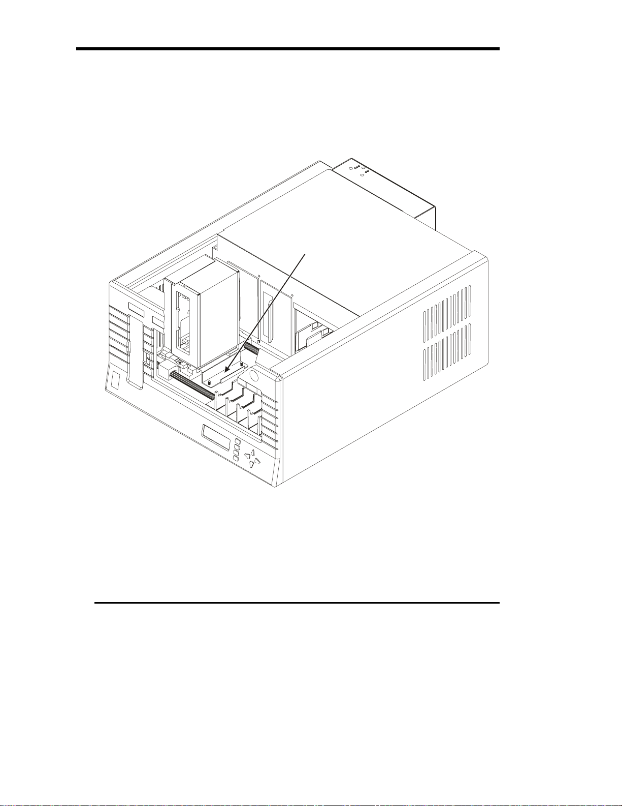
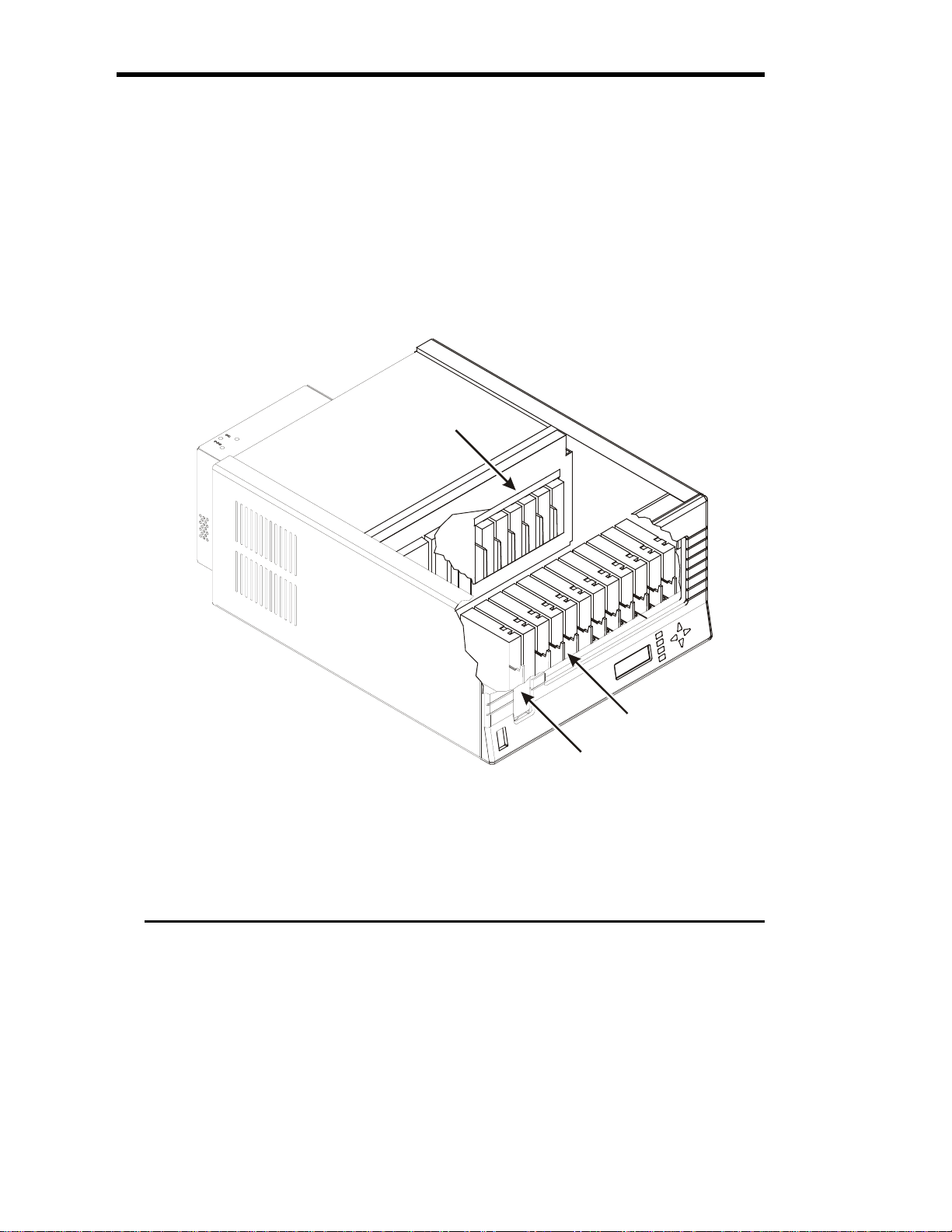
1. Inside the Scalar 218FC cartridge storage bay, locate the red shipping bracket mounted on the floor.
2. Remove the wing nuts that secure the shipping bracket to the floor.
Remove this bracket
Removing the Shipping Bracket (Desktop Scalar 218FC shown)
3. Pull the shipping bracket off the studs and remove it from the Scalar 218FC.
4. Remove the packing foam located between the left chassis wall and the Media Picker.
8 Getting Started
Page 19
r
Prepare and Install the Data Cartridges
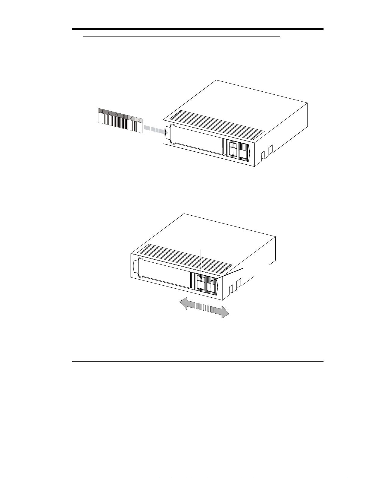
Barcode Labels
To install the barcode labels, position the label with the numbers upright, as shown in the illustration below,
sliding the label under the ridges on the sides of the cartridge recess.
Barcode Labels
Write-Protect Switch
1. Set the write-protect switch (see illustration below) on each cartridge to the appropriate position. Use
your finger to push the switch in one of the directions shown in the following illustration.
Orange
Indicato
Write-protect
Switch
Write-protected
Write-enabled
DLT Cartridge Write-Protect Switch
Getting Started 9
Page 20
Install Data Cartridges
Desktop Scalar 218FC
1. If necessary, unlock the sliding access panel by placing the key in the lock, and turning it one-half turn
ccw (left) to unlock.
2. Open the sliding access panel by sliding it to the rear of the Scalar 218FC.
Rack-mount Scalar 218FC
1. If necessary, unlock the front panel and slide it towards you until the slide stops engage.
All Scalar 218FC Units
1. Place each of the cartridges into the library storage slots. Install all cartridges with the barcode label
facing forward and the write-protect switch at the top.
Cartridges 12-17
10 Getting Started
Cartridge Locations
Cartridges 2-11
Mailbox or cartridge 1
Page 21

Note
The design of the six rear slots and the Mailbox slot prevents
you from incorrectly installing the cartridges. When powered-on,
the Scalar 218FC senses the orientation of each cartridge
installed in the 11 front slots. The library will sound the error
alarm and display a message on the LCD warning of any
incorrectly installed cartridges in these slots.
Install Cleaning Cartridge (Optional)
If your backup software is capable of scheduling and performing a drive cleaning cycle automatically, you
may want to dedicate a cartridge storage slot to a cleaning cartridge. After using all cleaning cycles, remove
the cleaning cartridge and install a new one. Refer to Chapter 5: Operations and Maintenance, section
Cleaning the Drive Head, for information on determining when a new cleaning cartridge is needed.
Close and Lock the Sliding Access Panel or
Scalar
1. On the desktop Scalar 218FC, close the sliding access panel by sliding it forward.
2. Insert the key into the front panel lock and turn ½-turn clockwise to lock the sliding access panel in
place.
3. Remove the key from the lock.
4. On the rack-mount Scalar 218FC, slide the Scalar back into the rack until the slam-lock engages.
5. Insert the key into the slam-lock and turn ½-turn clockwise to lock the Scalar into the rack.
6. Remove the key from the lock.
Preparing the Host Computer System
Power Off the Computer
1. Turn off the power switch.
Confirm and/or Install the Fibre Channel Host
Interface
Your Scalar 218FC must be connected directly to a fibre channel host bus adapter card installed in the
computer or through a fibre channel hub. Install the fibre channel interface (card or hub) before connecting
your Scalar library. Refer to the instructions supplied with your selected fibre channel interface.
Getting Started 11
Page 22

Backup Software
A variety of backup and data storage software is available for use with your Scalar 218FC. Special backup
software should not be required to operate with the fibre channel interface since the same SCSI commands
are simply sent over the fibre channel interface to the target device. Please check with ADIC Sales or
Customer Assistance if you have a question on the compatibility of a particular software package.
Now you are ready to connect your Scalar 218FC to your host computer. Follow the instructions provided in
the next chapter.
12 Getting Started
Page 23

Chapter
Connecting the Scalar 218FC Library
This Chapter …
❐ provides instructions for physically connecting your Scalar 218FC to your host
system.
❐ steps you through the final phase of the installation process.
13
Page 24

Installing the Interface Cables
Follow the steps on the following pages to connect your Scalar 218FC to your host computer and the Fibre
Channel bus. This involves installing cables onto the connectors at the rear of the Scalar 218FC. See the
section titled: Rear Panel Indicators, Switches and Connectors in Chapter 4 Equipment Description for an
illustration showing the positions of the connectors on the rear panel of the Scalar 218FC.
Fibre Channel Connection
Your Scalar 218FC provides support for Multi-Mode Fibre at 1.0625 Gbaud using dual SC connectors:
1. Connect the 3-meter, 50-micron, non-OFC cable (supplied with your Scalar 218FC) between the SC
connectors on the Host Bus Adapter (HBA) installed in your host computer or to a fibre channel hub,
and the SC connectors on the rear of the Scalar 218FC. The connectors are keyed to prevent improper
installation of the cable.
Fibre Channel Interface Serial Port
The modular jack on the rear panel of your Scalar 218FC provides an RS-232 connection that can be used to
configure the fibre channel subsystem, monitor diagnostic status, or update the firmware. To connect the
serial cable:
1. Make sure that power is off to the Scalar 218FC.
2. Connect the serial cable plug into the serial connector of the host computer and the modular plug to the
serial port connector of the Scalar 218FC.
10Base-T Ethernet Connection
Your Scalar 218FC supports Ethernet connectivity to provide enhanced configuration capabilities. All
functions available through the Fibre Channel Interface Serial Port are available through Ethernet. For
example, if you are going to download upgraded firmware using the serial port, you will need to have a copy
of the firmware on the host computer hard drive or on a diskette before beginning the procedure. Using
Ethernet, however, you can log into a BBS or a world-wide web site and download firmware directly to the
Scalar 218FC. If you plan to use the Ethernet capability:
1. Connect an Ethernet cable between your network and the Ethernet connector on the rear panel of the
Scalar 218FC.
Setting the SCSI IDs
Your Scalar 218FC consists of three SCSI devices; the two DLT drives and the library robotics. Each SCSI
device in your Scalar 218FC must be set to a unique ID. The ID for the robotics is set by selecting it through
the Operator Panel, Off-Line Mode, Configuration Menu, Set SCSI ID option (see sub-subsection titled: Set
SCSI ID, subsection Configuration Menu, section Off-Line Mode Menus in Chapter 4 Equipment
Description). Set each drive ID by selecting the appropriate ID number on the switch located on the back of
14 Connecting the Scalar 218FC Library
Page 25
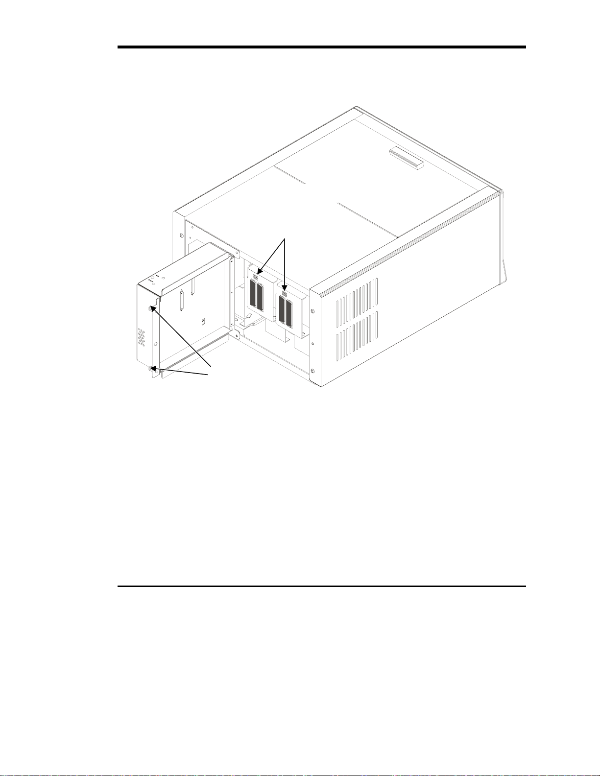
the drive assembly. Access the switches by opening the Scalar 218FC fibre channel subsystem cover on the
rear panel as shown in the following illustration:
1. Loosen the two thumbscrews that secure the right side of the cover to the rear panel by turning each of
them counter-clock-wise until the internal spring pushes the screw away from the mounting hole.
Some details not shown for clarity
Drive SCSI ID Switches
Thumbscrews
Drive SCSI ID Switches
Connecting the Scalar 218FC Library 15
Page 26
Powering on the System
❐ Plug the power cord into the back of your Scalar 218FC.
❐ Plug the power cord from the Scalar 218FC into a grounded electrical outlet.
Use caution when plugging the power cord into an electrical outlet.
Hazardous voltages are present in the sockets of the outlet.
❐ Plug the power cord from your host computer into a grounded electrical outlet.
❐ Turn on power to your Scalar 218FC.
❐ Turn on power to the host computer.
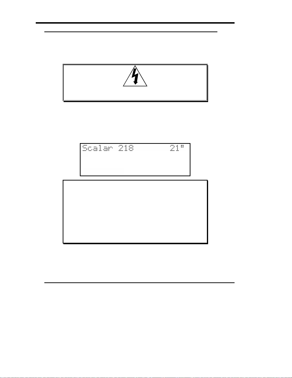
The following illustration shows the Operator Panel LCD message displayed when your Scalar 218FC has
completed the boot and initialization process.
Notes
With the factory default conditions unchanged, your Scalar
218FC will sign-on as a Scalar 218.
Your Scalar 218FC displays its current internal temperature
(in degrees centigrade). Whenever the internal temperature
meets or exceeds 40º C, an alarm will sound and the
“**HIGH TEMP ALARM**” message will appear on the LCD.
The alarm will quit and the message will be removed from the
LCD when the temperature falls below 40º C.
16 Connecting the Scalar 218FC Library
Page 27

Chapter
Configuring the Fibre Channel
Subsystem
This Chapter …
❐ provides instructions for configuring the fibre channel subsystem of your
Scalar 218FC.
❐ steps you through the final phase of the installation process.
17
Page 28
Configuring Your Communications Terminal
The fibre channel subsystem of your Scalar 218FC includes an embedded high-performance 32-bit
microprocessor with its own firmware located in Flash EEPROM. The Configuration Program, part of this
firmware, allows you to configure the subsystem, monitor subsystem diagnostic results, and download new
subsystem firmware. For information on configuring the robotics subsystem of your Scalar 218FC, refer to
section titled: Off-Line Mode Menus in Chapter 4 Equipment Description.
This manual and the Configuration Program make references to the “FCR 100” in discussions on fibre
channel configuration, monitoring of diagnostic results, and firmware downloading procedures. In these
instances, “Scalar 218FC fibre channel subsystem” and “FCR 100” are interchangeable.
To configure the fibre channel subsystem of your Scalar 218FC, to monitor diagnostic results or to download
new subsystem firmware, you need to use a host computer application that supports the X-modem data
transfer protocol. The following example uses the HyperTerminal application included in Windows NT 4.0.
Other applications may use different procedures and com ports, but notice that the baud rate, number of data
bits, number of stop bits, whether parity is enabled and what type of flow control to use must be set for your
serial communications port as given in this example.
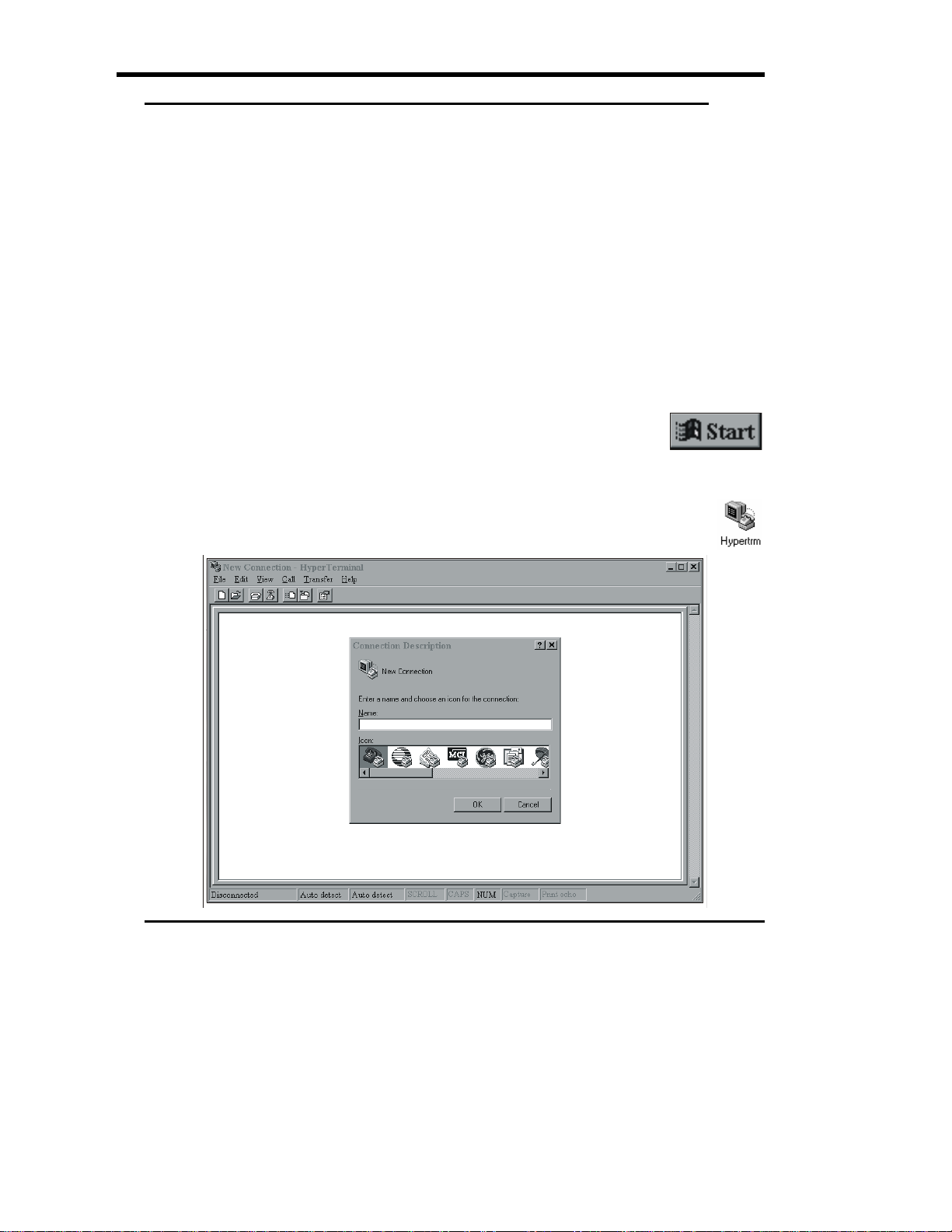
1. Select Programs from the Start Menu by clicking on the Start Button.
2. Select Accessories from the Programs menu.
3. Select HyperTerminal from the Accessories menu.
4. Click on the Hypertrm icon in the HyperTerminal program group.
5. A new HyperTerminal window appears with a dialog box for you to enter
a name for your hyperterminal and to select an icon to represent the
Hyperterminal in future sessions.
18 Configuring the Fibre Channel Subsystem
Page 29
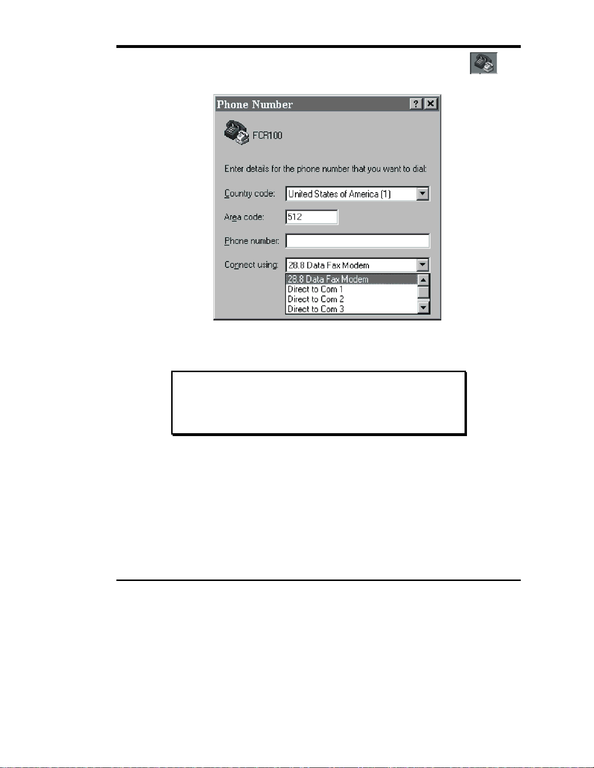
6. For this example we will name our Hyperterminal FCR 100 and select the Dial-in icon:
7. Click on OK. Now the Phone Number dialog box appears.
You do not have to enter a phone number, since you will be connecting directly through your serial port.
8. From the Connect using: pull-down menu, select the communications port assigned to your serial
port.
Note
This example uses COM2 for the serial port. You may use any
serial port that supports baud rates of at least 9600 bits per
second.
Configuring the Fibre Channel Subsystem 19
Page 30
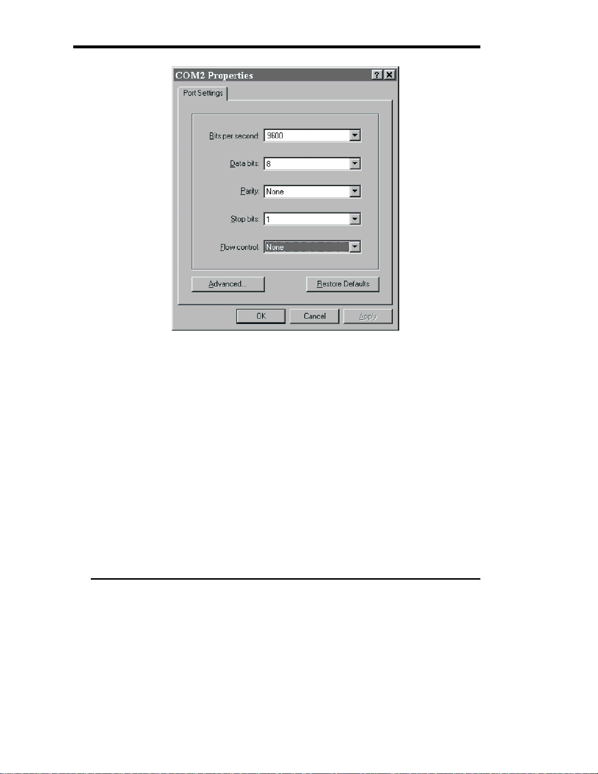
9. Click on OK. The Com PORT Properties dialog box appears:
Set your port settings to those shown in this dialog box:
Bits per second (baud rate)
Data bits
Parity
Stop bits
Flow control
9600 (default), 19200, 38400, 57600, or 115200
8
None
1
None
10. Click on OK.
11. Repeatedly press ENTER on the host computer until the Configuration Program main menu appears in
the command prompt area of HyperTerminal; The Build Level is the firmware level of the fibre channel
subsystem:
ADIC FCR100/CP4100 Fibre Channel/SCSI Router Configuration
Build Level: a9802
1) Perform Configuration
2) Do a Trace Dump
3) Reboot
4) Download a New Revision of the Firmware
Command >
20 Configuring the Fibre Channel Subsystem
Page 31

Notes
You may have to set the Bits per second (baud rate) in the
COM2 Properties dialog box to a higher value to establish
serial communications between your Scalar 218FC and your
computer. If the Configuration Program main menu does not
appear after pressing ENTER several times, change the baud
rate to the next higher value and repeat step 11. Continue
increasing the baud rate until the menu appears.
The Build Level: a9802 in the main menu is the current
version of fibre channel subsystem firmware installed in your
Scalar 218FC.
Configuring the Fibre Channel Interface
Introduction
The Scalar 218FC Configuration Program allows you to control many configuration settings through the
fibre channel serial interface or through the Ethernet connectivity capability. Among these are:
Baud rate of the serial port
Fibre Channel configuration
SCSI configuration
Ethernet configuration
Fibre Channel-to-SCSI mapping
Trace level settings
The default configuration settings of the Scalar 218FC are adequate for most applications. Configuration
settings may be changed and saved. They become the new default settings the next time you start your Scalar
218FC.
Repeatedly press ENTER on the host computer until the Configuration Program main menu appears on the
monitor:
ADIC FCR100/CP4100 Fibre Channel/SCSI Router Configuration
Build Level: a9802
1) Perform Configuration
2) Do a Trace Dump
3) Reboot
4) Download a New Revision of the Firmware
Command >
Configuring the Fibre Channel Subsystem 21
Page 32

Configuration
To configure the Scalar 218FC fibre channel interface, press 1 under the Configuration Program menu. This
displays the Configuration Menu:
Configuration Menu
Build Level: a9802
1) Baud Rate Configuration
2) Fibre Channel Configuration
3) SCSI Configuration
4) Ethernet Configuration
5) Fibre Channel to SCSI Mapping Configuration
6) SCSI to Fibre Channel Mapping Configuration
7) Trace Settings Configuration
8) SNMP Configuration*
A) Save Configuration
B) Restore Last Saved Configuration
C) Reset Configuration to Factory Defaults
X) Return to main menu
Notes
Most of the factory default settings within this section
should not have to be modified. The following descriptions
of each menu choice are provided so that you will have a
better understanding of how the fibre channel subsystem
functions.
Menu choice 6) SCSI to Fibre Channel Mapping
Configuration is not supported by your Scalar 218FC.
Call the ADIC Technical Assistance Center at (800) 827-2822
if any default settings do not meet the desired requirements.
Baud Rate Configuration
The baud rate is the rate of speed used by the Scalar 218FC Fibre Channel serial port to communicate with
another serial device. To configure the baud rate, press 1. This displays the following menu of choices:
Baud Rate Configuration Menu
Build Level: a9802
1) * 9600 2) 19200
3) 38400 4) 57600
5) 115200
22 Configuring the Fibre Channel Subsystem
Page 33

X) Return to previous menu:
The Baud Rate Configuration Menu displays a list of possible baud rates accepted by the Scalar 218FC fibre
channel interface. The default baud rate is 9600.
To select a different baud rate than the default:
1. Press the number corresponding to the desired baud rate in the listing.
To abort baud rate configuration, press X to return to the Scalar 218FC Fibre Channel Configuration Menu.
Note
Alphabetical menu and list choices in the Configuration Program
are
not
case sensitive. Uppercase and lowercase characters may
be used interchangeably.
2. Press X on the Baud Rate Configuration menu to return to the Configuration Menu.
3. Press A on the Configuration Menu to save the new baud rate setting.
Fibre Channel Configuration
Each Fibre Channel node is assigned a unique world wide name based on a unique vendor identifier that is
registered with IEEE. The World Wide Name is a 64 bit value. This value is broken into a 32-bit high-order
word and a 32-bit low-order word for configuration. An ADIC World Wide Name has the following format:
High-order
Low-order
To perform fibre channel configuration, press 2 in the Configuration Menu. This displays the following
menu of choices:
Fibre Channel Configuration Menu
Build Level: a9802
Current Fibre Channel Configuration:
World Wide Name High: 0x10000011
World Wide Name Low: 0x10000001
Use Hard ALPA: No
This menu displays:
The current value of the high-order word of the Fibre Channel World Wide Name
The current value of the low-order word of the Fibre Channel World Wide Name
The current value of the Hard Source ID (Use Hard ALPA) flag
You can change any of these three values.
10 00 00 E0
02
1) Change World Wide Name High
2) Change World Wide Name Low
3) Toggle Hard ALPA Usage
X) Return to previous menu
xx xx xx
Configuring the Fibre Channel Subsystem 23
Page 34

Note
Certain Host Bus Adapters (HBA’s) may require that you change
the Use Hard ALPA: No (default) to Use Hard ALPA: Yes. Call
ADIC Technical Support at (425) 883-HELP (4357) for additional
information.
World Wide Name High
This is the high-order word of the World Wide Name associated with a Fibre Channel entity.
To change the high-order word of the World Wide Name:
1. Press 1 in the Fibre Channel Configuration Menu. The Scalar 218FC Fibre Channel Serial Interface
displays the following prompt:
Enter new World Wide Name High value >
2. Enter the high-order word of your new World Wide Name.
If the value you specify is not a valid World Wide Name, the system will display the following warning:
ERROR:
Invalid World Wide Name Value!
Press Any Key to Continue...
World Wide Name Low
This is the low-order word of the World Wide Name associated with the Fibre Channel entity.
To change the low-order word of the World Wide Name:
3. Press 2 in the Fibre Channel Configuration Menu. The Scalar 218FC Fibre Channel Serial Interface will
display the following prompt:
Enter new World Wide Name Low value >
4. Enter the low-order word of your new World Wide Name.
If the value you specify is not a valid World Wide Name, the system will display the following
warning:
ERROR:
Invalid World Wide Name Value!
Press Any Key to Continue...
Hard ALPA Usage. This setting allows you to specify whether you can change the Fibre Channel Source
ID. If Use Hard ALPA is set to Yes (TRUE), then the Source ID may be changed. If Use Hard ALPA is
set to No (FALSE), then the Source ID may not be changed.
To change the Use Hard ALPA:
5. Press 3 in the Fibre Channel Configuration Menu.
This toggles the setting of Use Hard ALPA between Yes and No. If you toggle to yes, the menu adds a
selector to allow a hard address value and an address value of 0x1 is set.
6. Press X to return to the Configuration Menu.
24 Configuring the Fibre Channel Subsystem
Page 35

7. Press A on the Configuration Menu to save the new Fibre Channel configuration.
Configuring the Fibre Channel Subsystem 25
Page 36

SCSI Configuration
The SCSI configuration selection allows you to change the Initiator SCSI ID as well as to add or remove a
target SCSI ID.
SCSI Configuration Menu
Build Level: a9802
Current SCSI Configuration:
Initiator SCSI ID: 7
Target SCSI ID(s):
Reset SCSI Bus on Boot: Yes
SCSI Initial Discovery Delay: 15000 ms
1) Change Initiator SCSI ID
2) Add Target SCSI ID
3) Remove Target SCSI ID
4) Toggle SCSI Reset Operation
5) Change Discovery Delay Time
X) Return to previous menu
This menu displays:
the current SCSI Initiator ID
a list of the current SCSI Target IDs
the current value of the SCSI bus reset flag
a menu of valid SCSI configuration operations.
The operations to change these values are described below.
Change Initiator SCSI ID. The Initiator SCSI ID is the ID of the SCSI device that requests an operation to
be performed. To change the initiator SCSI ID:
Note
In any case
, do not enter Target SCSI IDs. It should not be
necessary to change the Initiator SCSI ID setting.
1. Press 1 while in the SCSI Configuration Menu. The Configuration Menu displays the following prompt:
Enter new Initiator SCSI ID >
2. Enter the new SCSI Initiator ID. The Configuration Menu accepts values between 0 and 15. The Scalar
218FC allows a target to have more than one ID.
3. After specifying your new SCSI Initiator, press Enter.
If you specify an invalid value, the Configuration Menu displays the following message:
ERROR:
26 Configuring the Fibre Channel Subsystem
Page 37

Invalid SCSI ID. Valid values are 0 - 15.
Press Any Key to Continue...
If the new initiator is in the list of Target SCSI ID(s), you must remove it. See Remove Target SCSI
ID, below. This prevents a SCSI device from being both initiator and target.
4. Press X to return to the Configuration Menu.
5. Press A to save the new SCSI configuration.
Add Target SCSI ID. The target SCSI ID is the ID of the SCSI device receiving a request. You may have
more than one ID as a SCSI target on the Scalar 218FC. To add a Target SCSI ID:
1. Press 2 while in the SCSI Configuration Menu. The Configuration Menu displays the following prompt:
Add new Target SCSI ID >
2. Enter a new SCSI Target ID. The Scalar 218FC accepts values between 0 and 15.
The new Target ID is added to the list of Target SCSI IDs under the SCSI Configuration Menu.
If you specify an ID that is already on the list of Target SCSI IDs, no change to the current list is made.
If you specify a number that is out of range, the Configuration Menu displays the following error:
ERROR:
Invalid SCSI ID. Valid values are 0 - 15.
Press Any Key to Continue...
3. Press X to return to the Configuration Menu.
4. Press A to save the new SCSI configuration.
Toggle SCSI Reset Operation. You can set the Scalar 218FC fibre channel subsystem to reset the SCSI
bus on boot. By default, this setting is Yes. To toggle the SCSI reset setting:
1. Press 4 under the SCSI Configuration Menu. The resulting display will reflect the setting change.
Change Discovery Delay Time. You can set the Scalar 218FC fibre channel subsystem to reset the SCSI
bus on boot. By default, this setting is Yes. To toggle the SCSI reset setting:
Ethernet Configuration
To select Ethernet Configuration, press 4 while in the Configuration Menu.
Ethernet Configuration Menu
Build Level: a9802
Current Ethernet Configuration:
Ethernet Physical Address : Unique value (set at factory)
IP Address : 001.001.001.001 (default value)
Subnet Mask : 255.255.255.0 (default value)
1) Change Ethernet Physical Address
2) Change IP Address
3) Change IP Subnet Mask
X) Return to previous menu
The Ethernet Configuration Menu displays:
the current Ethernet Physical Address
Configuring the Fibre Channel Subsystem 27
Page 38

the current Scalar 218FC Fibre Channel IP Address
the current Scalar 218FC Fibre Channel IP Subnet Mask.
The operations to change these values are described below.
Ethernet Physical Address. The Ethernet Physical Address is sometimes referred to as the MAC
address. It is a unique 48-bit value that is based on a vendor ID assigned by the IEEE. To change the Scalar
218FC’s physical Ethernet address:
1. Press 1 while in the Ethernet Configuration Menu. The Configuration Menu displays the following
prompt:
Enter new Ethernet Physical Address >
2. Enter your new Ethernet physical address and press Return.
If you enter an invalid Ethernet address, the Serial Interface displays the following error:
ERROR:
Invalid Ethernet Address!
Press Any Key to Continue...
3. Press X to return to the Configuration Menu.
4. Press A to save the new Ethernet Address.
IP Address. The IP address is used by the TCP/IP protocol to route information in a TCP/IP network. A
systems administrator usually assigns the IP address. To change the Scalar 218FC Internet (IP) address:
1. Press 2 while in the Ethernet Configuration Menu. The interface displays the following prompt:
Enter new IP Address >
2. Enter the new IP address and press Return.
If the IP address you specify is invalid, the following error message is displayed:
ERROR:
Invalid input!
Press Any Key to Continue...
3. Press X to return to the Configuration Menu.
4. Press A to save the new IP Address.
IP Subnet Mask
The IP subnet mask is used by TCP/IP protocol to establish a path to a default TCP/IP gateway. A systems
administrator usually assigns this value. To change the IP subnet mask:
1. Press 3 while in the Ethernet Configuration Menu. The following prompt is displayed:
Enter new Subnet Mask >
2. Enter the new IP subnet mask and press Return.
If you enter an invalid IP subnet mask, the following message is displayed:
ERROR:
Invalid input!
Press Any Key to Continue...
3. Press X to return to the Configuration Menu.
4. Press A to save the new IP subnet mask.
28 Configuring the Fibre Channel Subsystem
Page 39

Fibre Channel-to-SCSI Mapping Configuration
For a discussion of Fibre Channel-to-SCSI mapping, see Appendix A. To configure Fibre Channel-to-SCSI
mapping, select item 5 from the Configuration Menu. This presents the following display:
Fibre Channel to SCSI Configuration Menu
Build Level: a9802
Current Fibre Channel to SCSI Mapping Mode is Auto-assigned
1) Display Attached SCSI Devices, LUN Priority
2) Display Attached SCSI Devices, Target ID Priority
3) Display Attached SCSI Devices, Bus Number Priority
4) Change the Fibre Channel to SCSI Mapping Mode
X) Return to Previous Menu
LUN Priority Display. To view LUN priorities of attached SCSI devices:
1. Press 1 while in the Fibre Channel-to-SCSI Configuration Menu.
The Configuration Menu displays a screen similar to the following:
Querying SCSI devices, please be patient ...
Currently Attached Devices
Build Level: userLevel
BUS TGT LUN DEVICE DESCRIPTION
0 1 0 Scalar 448
0 2 0 Quantum DLT 7000
0 3 0 Quantum DLT 7000
X to return, <enter> for more >
Target ID Priority Display. To display the target ID priorities of SCSI devices, select 2. This results in a
display similar to the one shown above.
Bus Priority. Item 3 has no significance on the Scalar 218FC, since it only has one SCSI bus. Selecting this
choice results in the following error:
ERROR:
There is only one bus on this device
Press Any Key to Continue...
Fibre Channel-to-SCSI Mapping Mode. This allows you to select the way in which Fibre Channel
addresses are mapped to SCSI addresses.
Pressing 4 on the Fibre Channel-to-SCSI Mapping Mode Configuration Menu displays the following menu of
selections:
Fibre Channel to SCSI Mapping Mode Configuration Menu
Build Level: a9802
Current Fibre Channel to SCSI Mapping Mode is Auto-assigned
1) Set to SCC
2) Set to Indexed
3) Set to Auto-assigned, LUN priority
Configuring the Fibre Channel Subsystem 29
Page 40

4) Set to Auto-assigned, target ID priority
5) Set to Auto-assigned, bus number priority
X) Return to Previous Menu
Notes
If your selected HBA supports SCC Mode set the SCSI
Mapping Mode to SCC.
The factory default setting is: 5) Set to Auto-assigned, bus
number priority.
At the head of the display is the current value of the Fibre Channel-to-SCSI Mapping Mode. The default
value is SCSI Controller Command (SCC). There are five possible mapping modes:
SCC— Use the SCSI-3 Controller Command Set (SCC) Logical Unit Addressing method. This mode
requires that the host device driver is capable of addressing a controller device. In this mode, the
controller will respond directly to commands issued using the Peripheral Device Addressing Method.
Commands addressed using the Logical Unit Addressing Method will be routed to the appropriate SCSI
device as specified by the host.
Indexed—provides a user-configurable table that maps FCP LUN values to SCSI devices directly. In
this mode, the controller is not addressable by the host. Configuration allows for sequential FCP LUN
values (0, 1,
saved in FLASH memory and will persist across power cycles. Various editing assists are provided for
creating and modifying this table.
Auto-assigned, LUN priority—Auto assigned mode is similar to indexed mode: a table is used to map
FCP LUN values to SCSI addresses. However, this table is created at power up and does not persist
across reboots or power cycles. Discovery is performed on the SCSI bus, and each device is added to the
table in the order in which it is discovered.
In LUN priority, as discovery is performed, the LUN value is incremented after the Target value. Therefore,
as discovery is performed, all SCSI targets are identified before subsequent LUNs are identified.
Auto-assigned, target ID priority—As discovery is performed, the Target value is incremented after the
LUN. Therefore, all LUNs appear adjacent to the target device in the table.
Auto-assigned bus number priority—This option is not relevant to the configuration of the FCR100,
which has only one bus.
To change the Fibre Channel-to-SCSI mapping mode:
1. Press the number corresponding to the desired mapping mode.
2. Press X to return to the Configuration Menu.
3. Press A on the Configuration Menu to save the new mapping configuration.
2,...) to be mapped to arbitrary SCSI BUS:TARGET:LUN addresses. This table can then be
SCSI-to-Fibre Channel Mapping
The SCSI-to-Fibre Channel Mapping option is not supported by your Scalar 218FC.
30 Configuring the Fibre Channel Subsystem
Page 41

Trace Settings Configuration
Trace Settings Configuration allows you to set the trace level for diagnostics. For performance reasons, trace
settings should all be turned off, except in cases where a problem might be detected by a trace. The default
configuration has all levels set to ON. Pressing 7 on the Configuration Menu results in the following display:
Trace Settings
Build Level: a9802
Level 0 : ON Level 1 : OFF
Level 2 : OFF Level 3 : OFF
Level 4 : OFF Level 5 : OFF
Level 6 : OFF Level 7 : OFF
U) Update Current Operating Trace Levels
X) Return to previous menu
Enter trace level to change >
Note
The Trace capability is provided for diagnostic purposes only.
You should only change the Trace Level settings when
instructed to do so by ADIC Technical Support. Call ADIC
Technical Support at (425) 883-HELP (4357) for additional
information.
To change the trace level:
1. Enter a trace level number corresponding to the trace level you wish to change. This toggles the current
value between ON and OFF.
2. After all settings have been toggled to the value you desire, you can make them permanent by selecting
U to update the current operating trace level. (Note that Step 4, below, is still necessary, however.
3. Press X to return to the Configuration Menu.
4. Press A to save the your configuration settings.
Save Configuration
Pressing A on the Configuration Menu saves all currently changed values. See the previous examples for the
use of this option.
Restore Last Saved Configuration
Pressing B on the Configuration Menu restores all values from the previously saved configuration.
Reset Configuration to Factory Defaults
Pressing C on the Configuration Menu restores the factory default configuration. The following table
summarizes the default settings:
Setting Value
Baud Rate
World Wide Name High
Configuring the Fibre Channel Subsystem 31
Unique value (set at factory)
9600
Page 42

World Wide Name Low
Hard Address Usage
Initiator SCSI ID
Target SCSI ID(s):
Reset SCSI Bus on Boot
Ethernet Physical Address
IP Address
Subnet Mask
Fibre Channel-to-SCSI Mapping Mode
Unique value (set at factory)
No
7
Yes
Unique value (set at factory)
001.001.001.001
255.255.255.0
Auto-assigned Bus Number Priority
Return to main menu
Pressing X on the Configuration Menu returns to the main configuration program. If you have made changes
to the configuration, the program will display the following message:
The configuration has changed and you have not saved the new configuration to
flash. The configuration must be saved to flash for it to take effect on the
next reboot!
Save the configuration now (Y/N)? n
SNMP Configuration
The following section describes the ADIC SNMP Management Information Base (MIB). Many of these
definitions are specific to ADIC products and are not currently publicly defined by the IETF (Internet
Engineering Task Force) or other public body. General parameters are described for SNMP gets and sets for
various functional areas of the Scalar 218FC, and appropriate standards are described.
Several Fibre Channel draft MIB definitions are available for review from:
ftp://ftp.isi.edu/internet-drafts/
ftp.dpt.com/t11/pub/fc/misc./
Your Scalar 218FC currently supports the ADIC private MIB, whose details follow.
Description
The fibre channel subsystem of your Scalar 218FC provides several interfaces, each of which sends and
receives data. Management functions are accessible out-of-band via the Ethernet port (10BaseT) that serves
as the initial access point for MIB data. The MIB is used to track statistics regarding the flow of data (from
Fibre Channel-to-SCSI and vice versa), as well as to allow for configuration changes to be made to the fibre
channel subsystem. Possible configuration changes are mostly concerned with the need to change addressing
modes depending upon customer needs.
The ADIC private MIB includes all information accessible from the serial user interface. This MIB is
included in the fibre channel subsystem firmware installed on your Scalar 218FC.
Interfaces
There are a total of four types of interfaces to the FCR100:
Fibre Channel
SCSI
Ethernet
32 Configuring the Fibre Channel Subsystem
Page 43

RS-232 (serial port)
The fibre channel subsystem of your Scalar 218FC is configured as follows:
1 SCSI F/W interface
1 Gigabit Fibre Channel interface (optical)
1 10BaseT Ethernet Port
1 RS-232 Serial Port
The serial and Ethernet ports are used primarily for fibre channel subsystem configuration and management.
(TCP/IP requests may also be serviced over the Fibre Channel ports (in-band) in future releases.) A
discussion of each of these ports and its associated MIB data follows. Configuration information for each
interface is contained in the following section as well.
Fibre Channel
Fibre Channel data reported includes frame and packet information, upper layer protocol (ULP) type (FCP or
IP), and other Fibre Channel-specific information. Draft MIBs for Fibre Channel N_Ports and F_Ports are in
the public realm.
ADIC proposes to support portions of two standard Fibre Channel MIBs as well as an ADIC private MIB.
The ADIC private MIB includes:
Groups for Fibre Channel Configuration
FC N_Port Physical Table
FC N_Port Statistics
SCSI-to-FC Mapping
FC-to-SCSI Mapping
SCSI
SCSI is not generally an SNMP managed protocol. The ADIC MIB, however, gathers SCSI information for
management purposes. This ADIC specific MIB provides information about the following:
number of I/O operations per bus
number of disconnects
abort count
total data counts in bytes
bus resets
vital product data from Inquiry command for each SCSI device
This information can be found in the SCSIStatisticsTable and the SCSIProductData Groups of the ADIC
private MIB.
Ethernet and Serial Interfaces
The Ethernet interface is used for configuration and management, so total traffic flow is relatively low. The
basic Ethernet configuration items are found in the Management Interfaces Table.
The serial port is provided for user configuration. The serial port baud rate will be kept in the Management
Interfaces Table.
Configuring the Fibre Channel Subsystem 33
Page 44

ADIC Private MIB
The following chart lists all attributes that can be specified using the ADIC private SNMP MIB. Included
with each attribute are the attribute’s read/write property and a brief description of the meaning of values
read or written.
Parameter Read/Write Description
fcConfigNodeName
Read/Write Worldwide name of a collection of N_Ports that
comprise a Node.
fcConfigNodeNumNPorts
fcConfigEnableReset
Read Only Number of N_Ports that comprise the named Node.
Read/Write Toggle for software reset. True indicates that resetting
the product via SNMP is allowed. NOTE: each time
the product is initialized this object is set to FALSE
(i.e. it is not sticky).
fcConfigUseHardAddress
Read/Write Toggle for address configuration. True indicates that
configuration of the source ID is allowed. False
indicates that the source ID may not be changed.
fcConfigSourceID
Read/Write 3 byte Source address. For arbitrated loop, this will be
the Hard Assigned AL_PA (preceded by 20 bytes).
fcConfigSCSIMode
fcConfigTraceMask
fcConfigReset
Read/Write Fibre Channel-to-SCSI mapping mode.
Read/Write Trace Level.
Read/Write Reset the product. Setting this object to TRUE will re-
start all the software (similar to powering the product
off, then on). The reset will only take place if
fcConfigResetEnable is also TRUE. NOTE: resetting
the product will disconnect all current Fibre Channel
connections.
fcConfigCommit
miSerialBaudRate
miMACAddress
miethernetIPAddr
miethernetIPNetmask
miCommunitySet
miCommunityGet
scsiConfigTable
scsiConfigEntry
scsiConfigIndex
scsiConfigInitID
scsiConfigTargetIDAdd
Read/Write Commit the configuration values to the flash memory.
Read/Write The baud rate for the serial interface.
Read/Write Physical address (MAC address).
Read/Write The IP address for this device.
Read/Write Ethernet Net Mask.
Read/Write SNMP Community name for Sets. Not supported.
Read/Write SNMP Community name for Gets. Not supported.
Read/Write A Table containing SCSI Configuration parameters.
Read/Write An entry in the SCSI Configuration Table.
Read Only Index into the SCSI Configuration Table.
Read/Write Initiator SCSI ID.
Read/Write Set this SCSI target ID.
Parameter Read/Write Description
scsiConfigTargetIDRemove
Read/Write Remove this SCSI target ID. The SCSI ID you specify
will no longer be a target.
34 Configuring the Fibre Channel Subsystem
Page 45

scsiConfigResetFlag
Read/Write Toggle SCSI Reset Operation. TRUE indicates that
the SCSI bus will be reset on boot.
fctoSCSIMapTable
fctoSCSIMapEntry
fctoSCSIMapIndex
A Table containing the Fibre Channel-to-SCSI Map.
An entry in the Fibre Channel-to-SCSI Map Table.
Read Only Index into the Fibre Channel-to-SCSI Map (SCSI
LUN).
fctoSCSIbus
fctoSCSItarget
fctoSCSILUN
scsitoFCMappingTable
Read/Write SCSI bus number.
Read/Write SCSI ID.
Read/Write SCSI LUN.
A Table containing information describing how SCSI
channels are mapped to the Fibre Channel.
scsitoFCMapEntry
scsitoFCMapIndexBus
scsitoFCMapIndexSCSIID
scsitoFCMapIndexLUN
scsitoFCMapDestID
scsitoFCMapLUNlo
scsitoFCMapLUNhi
fcNPortPhysTable
fcNPortPhysEntry
fcNPortPhysNPortIndex
An entry in the SCSI-to-FC Mapping Table.
Read Only Index into the SCSI-to-FC Map. SCSI bus number
Read Only Index into the SCSI-to-FC Map. SCSI ID.
Read Only Index into the SCSI-to-FC Map. SCSI LUN.
Read/Write The Fibre Channel Node number.
Read/Write SCSI LUN low bytes.
Read/Write SCSI LUN high bytes.
A Table containing N_Port Physical Characteristics.
An entry in the N_Port Physical Characteristics Table.
Read Only A unique number that identifies an N_Port/NL_Port.
This number ranges from 1 to the value of
fcNodeNumNPorts and its value remains constant for
the identified N_Port/NL_Port until the management
agent of the Node is re-initialized.
FcNPortSpeed
fcNPortMedia
fcNPortTransmitterType
fcNPortDistance
Read Only The transmission rate, an FC-0 physical characteristic.
Read Only Type of media, an FC-0 physical characteristic.
Read Only Type of transmitter, an FC-0 physical characteristic.
Read Only The maximum distance, an FC-0 physical
characteristic.
fcNPortLinkState
Read Only The state of the FC link. Pending indicates that the
initialization is still pending. Failed indicates that link
initialization has failed. Successful indicates that the
FC Link has initialized successfully.
fcNPortRTTOV
Read Only Receiver_Transmitter timeout value, used by the
receiver logic to detect Loss of Synchronization.
Parameter Read/Write Description
fcNPortTopologyModel
Read Only The topology model on the Link. The N_Port/NL_Port
may be attached to a Fabric, or attached to another
N_Port or to FC-AL (Arbitrated Loop). This value is
only meaningful if the FC Link has initialized
successfully. (i.e. fcNportLinkState = Successful)
Configuring the Fibre Channel Subsystem 35
Page 46

scsiStatisticsTable
scsiStatsEntry
scsiStatsIndex
scsiStatsIOs
scsiStatsDisconnects
scsiStatsAbortCount
A Table containing SCSI Statistics.
An entry in the SCSI Statistics Table.
Read Only Index into the SCSI Statistics Table.
Read Only The number of IO operations on the SCSI bus.
Read Only The number of Disconnects on the SCSI bus.
Read Only The of SCSI bus termination messages (i.e. ABORT,
ABORT TAG, CLEAR QUEUE, BUS DEVICE
RESET) which have terminated I/O processes.
scsiStatsBusResets
scsiProductDataTable
scsiPDEntry
Read Only The count of SCSI bus resets
Read Only A Table containing SCSI Product Data.
Read Only An entry in the SCSI Product Data Table.
(scsiPDIndex.)
scsiPDIndex
Read Only The Index into the SCSI Product Data Table. (The
SCSI LUN.)
scsiPDDeviceCode
scsiPDQualifier
scsiPDRemoveable
scsiPDANSIVersion
scsiPDECMAVersion
scsiPDISOVersion
ScsiPDRespFormat
ScsiPDLength
ScsiPDSoftReset
ScsiPDCommandQing
ScsiPDLinkedCommands
ScsiPDSyncTransfer
scsiPD16Bit
scsiPD32Bit
ScsiPDRelativeAddr
ScsiPDVendorID
ScsiPDProductID
ScsiPDRevLevel
FcNPortStatisticsTable
Read Only Device type code.
Read Only Device type qualifier.
Read Only Removable media.
Read Only Device type version.
Read Only Device type version.
Read Only Device type version.
Read Only Response Format.
Read Only Additional data length.
Read Only Support for Soft reset.
Read Only Support for Command Queuing.
Read Only Support for Linked Commands.
Read Only Support for sync transfer.
Read Only 16-bit wide SCSI support.
Read Only 32-bit wide SCSI support.
Read Only Support for Relative address.
Read Only Vendor ID.
Read Only Product ID.
Read Only Revision Level.
Read Only A table of NPort statistics.
Parameter Read/Write Description
FcNPSEntry
Read Only An entry in the NPort statistics table.
36 Configuring the Fibre Channel Subsystem
Page 47

FcNPSIndex
FcNPSInDeviceDataFrames
FcNPSOutDeviceDataFrames
FcNPSInLinkDataFrames
FcNPSOutLinkDataFrames
FcNPSInLCRFrames
FcNPSOutLCRFrames
FcNPSInPBSYFrames
FcNPSOutPBSYFrames
FcNPSInPRJTFrames
FcNPSOutPRJTFrames
FcNPSAborts
FcNPSLaserFaults
FcNPSLOS
FcNPSBadRXChar
FcNPSClearRegisters
Read Only A unique number that identifies an N_Port. This
number ranges from 1 to the value of
fcNodeNumNPorts and its value remains constant for
the identified N_Port until the management agent of
the Node is re-initialized.
Read Only The number of Device Data frames received by this
N_Port/NL_Port.
Read Only The number of Device Data frames transmitted by this
N_Port/NL_Port.
Read Only The number of Link Data frames received by this
N_Port/NL_Port.
Read Only The number of Link Data frames transmitted by this
N_Port/NL_Port.
Read Only Counter not implemented.
Read Only Counter not implemented.
Read Only The number of P_BSY frames received by this
N_Port/NL_Port.
Read Only The number of P_BSY frames transmitted by this
N_Port/NL_Port.
Read Only The number of P_RJT frames received by this
N_Port/NL_Port.
Read Only The number of P_RJT frames transmitted by this
N_Port.
Read Only Number of Aborts.
Read Only Number of laser faults.
Read Only Number of seconds of Loss of Signal.
Read Only Number of bad characters received.
Read/Write Clear (zero) all N-Port Statistics Registers.
Trace Dumps
The Trace Dump selection on the Configuration Program menu allows you to perform traces of Scalar 218FC
activity for diagnostic purposes. The trace levels defined in Trace Settings Configuration (see above)
determine the level of detail displayed. You can perform a trace dump of either the current or previous Scalar
218FC boot cycle (the period of operation between power on or reboot until either the trace dump is
performed or the system is powered off). If you encounter problems with your Scalar 218FC, you may be
asked by an ADIC Support Engineer to perform the following operation. To perform a Trace Dump:
1. Press 2 on the Configuration Program main menu. This displays the Trace Dump menu.
Trace Dump Menu
Build Level: a9802
1) Dump trace for the current boot cycle
2) Dump trace from the previous boot cycle
X) Return to previous menu
Configuring the Fibre Channel Subsystem 37
Page 48

2. Press 1 to perform a trace dump for the current Scalar 218FC boot cycle, or press 2 to trace the previous
boot cycle. The resulting display will be similar to the following, depending upon the trace levels set
during configuration.
399 ms 936 us Init Timer went off! Restart initialization...!
0 ms 24 us Trying to go on-line!
399 ms 937 us Init Timer went off! Restart initialization...!
0 ms 24 us Trying to go on-line!
399 ms 936 us Init Timer went off! Restart initialization...!
0 ms 24 us Trying to go on-line!
399 ms 937 us Init Timer went off! Restart initialization...!
0 ms 24 us Trying to go on-line!
399 ms 936 us Init Timer went off! Restart initialization...!
0 ms 24 us Trying to go on-line!
399 ms 937 us Init Timer went off! Restart initialization...!
0 ms 24 us Trying to go on-line!
399 ms 936 us Init Timer went off! Restart initialization...!
0 ms 24 us Trying to go on-line!
399 ms 937 us Init Timer went off! Restart initialization...!
0 ms 24 us Trying to go on-line!
399 ms 935 us Init Timer went off! Restart initialization...!
0 ms 23 us Trying to go on-line!
399 ms 939 us Init Timer went off! Restart initialization...!
0 ms 24 us Trying to go on-line!
399 ms 936 us Init Timer went off! Restart initialization...!
0 ms 24 us Trying to go on-line!
399 ms 935 us Init Timer went off! Restart initialization...!
0 ms 23 us Trying to go on-line!
399 ms 938 us Init Timer went off! Restart initialization...!
New Firmware Revisions
The Scalar 218FC uses a serial connection and the XMODEM protocol to update the firmware.
1. Press 4 (Download a New Revision of the Firmware) in the Configuration Program main menu. The
following prompt will be displayed:
Download Firmware Menu
Build Level: a9802
This will replace the current revision of the firmware.
A reboot will also be performed as part of this process.
Are you sure (Y/N)?
2. Press Y to download the firmware revision and reboot the Scalar 218FC.
38 Configuring the Fibre Channel Subsystem
Page 49

Downloading...
3. Pull down the Transfer menu on the HyperTerminal menu bar and click on Send File…, or click on the
Send button on the tool bar. This activates the Send File dialog box.
4. Enter the filename of the firmware version that you wish to download, or use the Browse button to
search for the file. This opens the Select File to Send dialog box.
5. Click on firmware to enter it into the File name text box, then click on Open.
6. Set the protocol in the Send File dialog box to XMODEM.
Configuring the Fibre Channel Subsystem 39
Page 50

7. Click on Send. The downloading process will proceed and the Scalar 218FC will reboot. The following
output is an example that may be different on your system.
.text: 0xa00d0000 → 0xfee10000, size: 0x00000688.
.data: 0xa00d0688 → 0xfee10688, size: 0x0004eadc.
.bss: 0xa011f170 → 0xfee5f170, size: 0x0001b130.
Should the download fail, you will see the following message:
Download failed
ERROR:
Downloading of firmware image failed!
Press Any Key to Continue...
Rebooting the Scalar 218FC
For configuration changes to take effect, you must reboot the Scalar 218FC.
To reboot the Scalar 218FC:
1. Press 3 under the Configuration Program. This displays the following confirmation prompt:
Reboot! Are you sure (Y/N)?
2. To reboot the Scalar 218FC, press Y; to abort, press N.
You are now ready to install the backup software – if it has not already been installed.
Installing the Backup Software
At this point you need to refer to your software installation guide for instructions on installing the backup
and controlling software for the Scalar 218FC onto the host computer.
After you have completed installation of the Scalar 218FC and of the software, you should run any
diagnostic test(s) supplied with the backup software to make sure that your unit is operating correctly.
After your library and host computer are connected, and the application software installed, the library is
ready for use. Just turn on the power switch.
40 Configuring the Fibre Channel Subsystem
Page 51

Chapter
Equipment Description
This Chapter …
❐ describes the switches, indicators and connectors on the front and rear of your
Scalar 218FC.
❐ describes the various functions available via the front panel buttons.
❐ describes the power-up procedure and messages on the front panel LCD
display.
41
Page 52

Front Panel Switches and Indicators
The following illustration shows the front panel switches and indicators.
On/Off switch
Display
Power Switch
MENU
ESC
42 Equipment Description
The four-line 20-character LCD shows current drive status of the Scalar 218FC
Library, allows access to change features or displays error messages.
The power switch turns the Scalar 218FC ON and OFF.
Press this button to enter or exit the Off-Line mode of operation.
Exits current menu and returns to previous menu.
4-line x 20-character LCD
Front of Scalar 218FC Library
Switches and Indicators
8-key keypad
Page 53

ALT
ENTER
Selects alternate function for another button.
Selects currently displayed item.
Selects previous item or value in menu, and moves cursor to previous line.
Selects next item or value in menu, and moves cursor to next line.
Selects previous field on same line, and scrolls message to the left.
When in the On-Line mode of operation, if pressed immediately after the ALT key
has been pressed, this key will cause the Picker to move to the extreme right.
Selects next field on same line, and scrolls message to the right.
When in the On-Line mode of operation, if pressed immediately after the ALT key
has been pressed, this key will cause the Picker to move to the extreme left.
Equipment Description 43
Page 54

Rear Panel Indicators, Switches and Connectors
The following illustration shows the indicators, switches and connectors on the rear of the Scalar 218FC
Library.
Fibre Channel Status
Fibre Channel SC
Fibre Channel Serial
Ethernet (10BaseT)
AC Input
FC
10Base-T
SCSI
FAULT
POWER
44 Equipment Description
Rear of Scalar 218FC
Rear Panel Fibre Channel Status Indicators (LEDs)
Indicates Fibre Channel activity when illuminated.
Indicates 10Base-T activity when illuminated.
Indicates SCSI activity when illuminated.
Indicates a failure in the Fibre Channel interface circuitry.
Indicates power is applied to the Fibre Channel interface circuitry.
Page 55

Rear Panel Connectors
AC Input Connector
Fibre Channel SC
Connector
Ethernet Connector
Fibre Channel Serial
Connector
Plug the AC power cord into this connector.
Connection for the Fibre Channel interface cables. Used to connect
the Scalar 218FC to the host computer Host Bus Adapter (HBA)
using a non-OFC optical cable.
Ethernet 10Base-T connectivity
Multi-function port. Used to monitor the Fibre Channel interface selftest, perform firmware upgrade of the FC interface, reboot the FC
interface, monitor the FC interface diagnostics. Also, used to
configure the Fibre Channel interface. Connect to a serial port on
your host computer.
How the Scalar 218FC Processes SCSI Commands
The fibre channel subsystem of your Scalar 218FC acts as a pass-through device that receives and transmits
SCSI Fibre Channel Protocol (FCP) packets. This allows the host equipped with a FC host bus adapter
(HBA), to access SCSI peripheral devices transparently over the fibre channel connection.
1. The host issues a SCSI command.
2. The fibre channel subsystem in the host encapsulates the command in the FC protocol and sends the
packet to the Scalar 218FC.
Equipment Description 45
Page 56

3. The fibre channel subsystem in the Scalar 218FC receives the packet, interprets the FC information, and
places the packet in memory.
4. The fibre channel subsystem processor interprets the SCSI information and programs the appropriate
SCSI or fibre channel subsystem to process the transaction.
5. The SCSI subsystem sends the command to the appropriate SCSI target (Scalar 218FC robotics, DLT
drive 1, or DLT drive 2).
6. The target executes the command and return information is sent to subsystem memory.
7. The subsystem processor encapsulates the return information in the FC protocol and sends the packet
back to the host.
46 Equipment Description
Page 57

Off-Line Mode Menus
The following diagram is a quick reference to the Scalar 218FC LCD menus described on the next few
pages.
Configuration Menu Diagnostics Menu Write Flash Memory Serial Dnld Flash
Buzzer Configuration Open Drive Door
ErrAlarm Yes/No Close Drive Door
Kybd Yes/No Firmware Revision
Set SCSI ID Map Slots & Drives
Library’s SCSI ID: X (0-7) Scan Bar Codes Yes/No
Product Sign-On Pos Picker at Slot
EXB-480: N Yes/No Slot ss (ss = 01-18)
Off-Line Time Pos Picker at Mbox
Max time: X min 1-99 minutes Pos Picker at Drv
Init Mapping Drv dd (dd = 01, 02)
Map Slots and Drives Yes/No Pick From Slot
Init Scan Barcodes Slot ss (ss = 01-18)
Scan Barcodes Yes/No Pick From Mailbox
Barcode Scanner Pick From Drive
Enable: Y Yes/No Drv dd (dd = 01, 02)
Verify SCSI Bus Place In Slot
Same Bus: Y Yes/No Slot ss (ss = 01-18)
Enable Mailbox Place In Mailbox
Enable Mailbox Yes/No Place In Drive
Adjust Slot Count Drv dd (dd = 01, 02)
Number of Slots ? Event Counters
Operation Log
Calibrate Position
Display Sensors
Run Demo
Equipment Description 47
Page 58

When powered-on, and after completing the initialization process, the LCD will appear as shown above.
❐ To access the Off-Line Mode menu, press the MENU key. The display will appear as follows:
❐ Use the UP or DOWN keys to scroll through the menu choices. Press ENTER to select the item
displayed on the top line. Use the RIGHT or LEFT keys to scroll through fields on the same line.
❐ To exit the Off-Line Mode menu and return to the On-Line Mode from anywhere in the menu,
press the MENU key.
❐ Press ENTER to select the Configuration Menu.
Configuration Menu
The Configuration Menu allows you to select the following operating parameters:
Buzzer Configuration Set SCSI ID (Library Robotics)
Product Sign-On Off-Line Time
Init Mapping Init Scan Barcodes
Barcode Scanner Verify SCSI Bus
Enable Mailbox Adjust Slot Count
48 Equipment Description
Page 59

Buzzer Configuration
Enables/disables the sounding of an alarm when an error message or warning alarm is displayed.
Enables/disables the beep sound when you press a keypad key.
❐ To enable the error alarm use the LEFT key to select the ErrAlarm field. Use UP or DOWN to
select "Y" to enable alarm or "N" to disable alarm. When the error alarm is enabled, a continuous
alarm tone will sound in the event of an error message. The alarm will sound until the condition
that caused the error has been removed or any key is pressed. To clear an error message from the
display, press ALT and ENTER.
❐ If you wish to change the status of the keyboard beep, use the RIGHT key to select the Kybd field.
Use UP or DOWN to select "Y" to enable a beep when you press a key or "N" to disable the beep.
Note
BUZZER CONFIGURATION default: Err Alarm: N, Kybd: Y
❐ Press ENTER to make the changes effective or press ESC to return to previous menu item.
Set SCSI ID
Lets you select the SCSI ID for the robotics on the library.
❐ Use UP and DOWN to select the desired ID. Press ENTER to execute the change. Confirm the
change by pressing ENTER again.
Note
SET SCSI ID default is Library’s SCSI ID:1.
Equipment Description 49
Page 60

Product Sign-On
Let’s you select how the Scalar Library appears to application software. The library can be set to sign-on as
an Exabyte
®
EXB-480™ library. This permits maximum application software compatibility.
❐ Use UP or DOWN to select “Y” or “N”. Press ENTER to execute the change.
Note
PRODUCT SIGN-ON default is EXB-480: N.
Off-Line Time
Lets you set the number of minutes the Scalar Library will remain in the Off-Line Mode. If someone leaves
the library in the Off-Line mode, after the pre-set number of minutes the library will automatically return to
the On-Line Mode. This assures that your automatic backup will be done even if the library has accidentally
been left off-line.
❐ Use UP or DOWN to select the number of minutes you wish the Scalar Library to remain in Off-
Line Mode. Press ENTER to execute the change.
Note
OFF-LINE TIME default setting is "2" minutes.
Init Mapping
50 Equipment Description
Page 61

Enables/disables the mapping of the storage slots whenever the Scalar Library is powered-up, after the
sliding access panel has been opened and then closed, or if a SCSI bus Reset occurs.
❐ To disable the mapping of slots use the UP or DOWN keys to select "N". Press ENTER to execute
the change.
Note
INIT MAPPING default setting is Y.
Note
Disabling INIT MAPPING by selecting “N” will force INIT
SCAN BARCODES to “N” ( see below).
Init Scan Barcodes
Enables/disables the scanning of the cartridge barcodes whenever the Scalar Library is powered-up, or
after the sliding access panel has been opened and then closed. The application software overrides the
setting of this parameter. If Barcode Scanner configuration is set to No, Initialize Scan Barcodes is
ignored, and the barcode reader is not available to the application software.
❐ To disable the scanning of barcodes use the UP or DOWN keys to select "N". Press ENTER to
execute the change.
Note
INIT SCAN BARCODES default setting is Y.
Note
Enabling INIT SCAN BARCODES by selecting “Y” will force
INIT MAPPING to “Y” ( see above).
Equipment Description 51
Page 62

Barcode Scanner
Enables/disables the barcode scanner. If disabled, the Initialize Scan Barcodes, Configuration Menu
parameter (see above), and the Scan Barcodes sub-function of the Map Slots Diagnostics Menu function
(see Appendix B), is ignored. If disabled, the barcode scanner is not available to the application
software.
❐ To disable the barcode scanner use the UP or DOWN keys to select "N". Press ENTER to execute
the change.
ENABLE BARCODE SCANNER default setting is Y.
Verify SCSI Bus
Note
Verifies that the SCSI devices within your Scalar 218FC (the library robotics and the drives) are
connected to a single SCSI channel. Some network operating systems need to know if the Scalar 218FC
SCSI devices are connected to more than one SCSI channel.
❐ To verify that the SCSI devices are connected to more than one SCSI channel use the UP or
DOWN keys to select "N". Press ENTER to execute the change.
Note
VERIFY SCSI BUS default setting is Y.
52 Equipment Description
Page 63

Enable Mailbox
Enables/disables the Mailbox as a cartridge input/output element. When your Scalar 218FC Mailbox is
enabled, there are 17 storage slots available to store data cartridges. The application software will use
the Mailbox slot to move cartridges into, and out of the library storage slots. When the Mailbox is
disabled, the slot is configured as storage slot number 18 and is available to store a data cartridge.
❐ To disable the Mailbox, and configure the slot as a storage location, use the UP or DOWN keys to
select "N". Press ENTER to execute the change.
ENABLE MAILBOX default setting is Y.
Adjust Slot Count
Note
Adjusts the number of storage slots available to the application. Dependent upon the setting of
ENABLE MAILBOX (see above). If the Mailbox is disabled, choices are 18 slots or 16 slots. If set for
16 slots, slots 17 and 18 (Mailbox slot) are disabled. If the Mailbox is enabled, choices are 17 slots or 16
slots. If set for 16 slots, slot 17 is disabled. Adjust Slot Count setting affects the maximum slot available
to Pos Picker At Slot, Pick From Slot, and Place In Slot functions available under the Diagnostics Menu.
Refer to Appendix B for a detailed description of these functions.
❐ To adjust the slot count, use the UP or DOWN keys to select between "18" or “16” if the Mailbox
is disabled, or select between “17” or “16” if the Mailbox is enabled. Press ENTER to execute the
change.
Note
ADJUST SLOT COUNT default setting is 18 if Mailbox is
disabled, and 17 if Mailbox is enabled.
Equipment Description 53
Page 64

Diagnostics Menu
The following functions are available under the Diagnostics Menu:
Open Drive Door Close Drive Door
Firmware Revision Map Slots & Drives
Pos Picker at Slot Pos Picker at Mbox
Pos Picker at Drv Pick From Slot
Pick From Mbox Pick From Drv
Place In Slot Place In Mbox
Place In Drv Event Counters
Operation Log Calibrate Position
Display Sensors Run Demo
For detailed descriptions of these functions, refer to Appendix B.
Note
We strongly recommend that only a qualified service technician
use these diagnostic functions. Some diagnostic functions
assume the Scalar Library has been configured correctly and
many of the normal built-in safety checks are turned off.
Misusing these diagnostic functions without the normal safety
checks could result in improper operation (or damage to media
and/or the Scalar Library).
Write Flash Memory
The Write Flash Memory mode is not applicable to the Scalar 218FC Library.
54 Equipment Description
Page 65

Serial Dnld Flash
The Serial Dnld (Download) Flash mode is used whenever you upgrade the Scalar Library firmware
using the serial port on the rear panel. When ADIC releases new firmware for the Scalar Library,
complete instructions on using Serial Dnld Flash mode and performing the upgrade will be included
with the firmware.
Equipment Description 55
Page 66

Chapter
Operation and Maintenance
This Chapter …
❐ describes normal operation features of the Scalar 218FC Library
❐ provides details on the media and drive head cleaning cartridge
❐ explains normal maintenance procedures
56
Page 67

Normal Operations
General Guidelines
Once your Scalar 218FC Library and your choice of application software are installed and configured,
you can automatically perform backup and restore operations via the application software. You do not
need to intervene unless the application software instructs you to exchange data cartridges through the
mailbox slot, or by reaching in through the sliding access panel.
Always follow these general-operating guidelines:
❐ Open the sliding access panel of the Scalar 218FC only when you must. Even if you power down
your library, you should keep the door closed to protect the internal components from dust.
❐ Use only the recommended types of media cartridges, described earlier in this manual.
❐ Clean each of the DLT drives once a month, or whenever the Use Cleaning Tape LED is
illuminated on a drive front panel (see the subsection titled Cleaning the Drive Head in the
Maintenance section later in this chapter).
Power-Up Checks
When you apply power to your Scalar 218FC, the Fibre Channel subsystem will perform a Power-on
Self-Test while the library (robotics) is performing the Power-Up Checks.
When you apply power to your Scalar 218FC, the library (robotics) will perform the following actions:
Verifies drive configuration and status.
Builds a valid cartridge inventory log.
Calibrates the positioning of the Media Picker.
When the library has completed the Power-Up Checks it will automatically place itself in On-Line
Mode.
Drive Power-on Self-Test
When you power up your Scalar 218FC Library, the DLT drives each perform a Power-on Self-Test
(POST) while the library is performing the Power-Up Checks. The sequence of events for each drive is:
1. The LEDs on the right front panel of the drive will turn on sequentially from top to bottom. All
LEDs will remain ON for a few seconds.
2. The LEDs on the left front panel of the drive will turn ON at the same time for about three seconds
and then turn OFF.
3. The Operate Handle, Write Protected, and Use Cleaning Tape LEDs will turn OFF. The
Tape in Use LED will blink while the tape drive initializes.
✔ If your external SCSI bus terminator has a Term Power LED it should also be illuminated.
Operation and Maintenance 57
Page 68

Drive Status
After completion of the drive POST and initialization, each drive will be in one of the four states listed
in the following table:
Drive State Indicator Displays and Actions
1. No cartridge is present
2. A cartridge is present
and the handle is closed.
3. A cartridge is present,
but the handle is open.
4. The drive detects an
error condition.
The drive POST completes in about 13 seconds on each drive, and the drives will respond normally to
all commands. However, it may take longer for the media to become ready.
A. The Tape in Use LED turns OFF.
B. The Operate Handle LED turns ON.
C. The handle is unlatched.
D. The drive beeps momentarily.
The drive loads the cartridge. When the Tape in Use LED stops
blinking and stays ON, the tape’s actual density lights. For example, if
the actual tape density is 2.6, then the LED turns ON next to the 2.6
label. When the Density Override LED blinks, you can select a
density. The drive is ready for use.
The Tape in Use LED turns OFF. The Operate Handle LED
flashes. The Scalar Library will close the handle and the drive will load
the cartridge. When the Tape in Use LED stops blinking and stays
ON, the tape’s actual density lights. For example, if the actual tape
density is 2.6, then the LED turns ON next to the 2.6 label. When the
Density Override LED blinks, you can select a density. The drive is
ready for use.
Then all right or left side LEDs blink repeatedly. You may try to
unload the tape and reinitialize the drive by pressing the Unload key
or turn power OFF and then ON again. The right or left side LEDs stop
blinking and the drive tries to reinitialize. The LEDs turn ON steadily
again and then turn OFF if the test succeeds.
58 Operation and Maintenance
Page 69

Drive Operating Conditions
Use the following table to determine each drive’s operating condition:
LED Label
(Right Indicator Panel)
Write Protected
Tape in Use
Use Cleaning Tape
Operate Handle
All Right Indicator
Panel LEDs or,
All Left Indicator
Panel LEDs
Color State Operating Condition
Orange ON
OFF
Yellow Blinking
ON
Yellow ON
Remains on after
unloading
cleaning tape
After cleaning,
turns on again
when reloading
data cartridge
Green ON
OFF
ON
Blinking
Tape is write-protected.
Tape is write-enabled.
Tape is moving.
Tape is loaded; ready for use.
Drive head needs cleaning, or the tape is bad.
Cleaning attempted, but tape expired, so
cleaning not performed.
Problem data cartridge. Try another cartridge.
OK to operate the Cartridge Insert/Release
Handle.
Do not operate the Cartridge Insert/Release
Handle.
POST is starting.
An error has occurred.
(continued on next page)
Operation and Maintenance 59
Page 70

LED Label
(Left Indicator Panel)
2.6 (DLT4000, DLT7000)
6.0 (DLT4000, DLT7000)
10.0 (DLT4000)
10.0/15.0
(DLT7000, DLT8000)
20.0
(DLT4000, DLT7000,
DLT8000)
35.0
(DLT7000, DLT8000)
40.0
(DLT8000)
Color State Operating Condition
Yellow ON
Blinking
Tape is recorded in 2.6 format.
Tape is recorded in another density. You
selected this density for a write from BOT.
Yellow ON
Blinking
Tape is recorded in 6.0 format.
Tape is recorded in another density. You
selected this density for a write from BOT.
Yellow ON (default)
Blinking
Yellow ON (default)
Blinking
Tape is recorded in 10.0 format.
Tape is recorded in another density. You
selected this density for a write from BOT.
Tape is recorded in 15.0 format.
Tape is recorded in another density. You
selected this density for a write from BOT.
Yellow ON (default)
Blinking
Tape is recorded in 20.0 format.
Tape is recorded in another density. You
selected this density for a write from BOT.
Yellow ON (default)
Blinking
Tape is recorded in 35.0 format.
Tape is recorded in another density. You
selected this density for a write from BOT.
Yellow ON (default)
Blinking
Tape is recorded in 40.0 format.
Tape is recorded in another density. You
selected this density for a write from BOT.
Compress
Yellow ON
OFF
Density Override
Yellow ON
OFF (default)
Blinking
All Right Indicator
Blinking A POST error has occurred.
Panel LEDs, or,
all Left Indicator
Panel LEDs
60 Operation and Maintenance
Compression mode enabled. (Compression
available only in 10.0, 15.0, 20.0, and 35.0
density.)
Compression mode disabled.
You selected a density from the front panel.
Density will be selected by the host (automatic).
You are in density selection mode.
Page 71

g
DLT Media
The data cartridge used in the DLT drive is housed in a four-inch plastic case and contains ½-inch metal
particle tape.
Write-
Ora
n
e
Write-protect
Write-
DLT Data Cartridge
The write-protect switch prevents or allows recording over existing data. To prevent recording or
deleting, place the write-protect switch to the write-protected position. When installing cartridges in the
library, place the switch in the write-enabled position (unless you do not wish to record on a specific
cartridge).
Notes
A small orange rectangle is visible whenever the cartridge is
write-protected (to the left).
The orange rectangle will not be visible whenever the
cartridge is write-enabled (to the right).
Store data cartridges in a dry, cool environment.
Never reset or power down your computer or Scalar Library
while a function is in process or a tape is moving.
Operation and Maintenance 61
Page 72

Opening the Sliding Access Panel
Caution
Do not open the sliding access panel unless you need to replace data cartridges,
or perform a maintenance operation.
Desktop Unit
A sensor monitors the position of the access panel. Whenever the panel is opened all Media Picker
activity stops and a SCSI UNIT ATTENTION is returned to the host. Drive activity is unaffected by the
position of the panel. When the panel is again closed, the Scalar 218FC resets, calibrates the Media
Picker, and waits for a command from the host.
❐ Insert the key into the lock and turn it to the left to unlock.
Warning
Wait until any current application operations are completed.
❐ Turn the lock ¼ turn in either direction and hold while pushing the sliding access panel toward the
rear of the Scalar 218FC.
Rack-mount Unit
A sensor monitors the position of the Scalar in the rack. Whenever the Scalar is pulled out from the
rack, all Media Picker activity stops and a SCSI UNIT ATTENTION is returned to the host. Drive
activity is unaffected by the position of the front panel. When the Scalar is pushed back into the rack,
the Scalar 218FC resets, calibrates the Media Picker, and waits for a command from the host.
❐ Insert the key into the front panel slam lock and turn it to the left to unlock.
Warning
Wait until any current application operations are completed.
❐ Turn the slam lock knob ¼ turn in either direction and hold while pulling the Scalar out of the rack.
62 Operation and Maintenance
Page 73

Using the Mailbox
On-Line Mode
Note
The application software can use the Mailbox as a cartridge
input/output element only if it is first enabled. See
Mode Menus, Configuration Menu, Enable Mailbox in Chapter 4
of this manual for additional information.
In the On-Line mode, the application software controls the Mailbox. The application may add, or
remove, a single cartridge, or a complete backup data set may be exchanged, one cartridge at a time.
The cartridge must be placed into or removed from the Mailbox slot manually, whenever the application
requests. When adding or removing a cartridge to/from the Mailbox slot, open the plastic window
covering the slot to provide access.
Off-Line Mode
Moving a Cartridge to a Drive or Storage Slot
Use the Mailbox to place a data or cleaning cartridge directly into a drive or a storage slot.
❐ Open the plastic door over the Mailbox slot.
❐ Place the cartridge into the slot with the write-protect switch up, and facing toward you.
Off-Line
❐ Close the plastic door.
❐ Use the Off-Line mode Diagnostics Menu Pick from Mailbox function to have the Picker
move a cartridge from the Mailbox slot to a drive or storage slot. See Appendix B Diagnostics
Menu, later in this manual, for complete descriptions of the Pick and Place functions.
Moving a Cartridge to the Mailbox Slot
Move a data or cleaning cartridge from a drive or storage slot to the Mailbox as follows:
❐ Use the Off-Line mode Diagnostics Menu, Place in Mailbox function to have the Picker
move a cartridge from a drive or storage slot to the Mailbox slot. See Appendix B Diagnostics
Menu, later in this manual, for complete descriptions of the Pick and Place functions.
❐ Open the plastic door over the Mailbox slot.
❐ Remove the cartridge from the Mailbox manually.
❐ Close the plastic door.
Operation and Maintenance 63
Page 74

Manually Loading/Unloading Cartridges to/from
the Storage Slots (Bulk Loading)
Media can be exchanged on a “bulk” basis by opening the access panel and exchanging any or all
cartridges in the slots. The application software will have to re-map the slots and re-scan the barcodes to
update its cartridge inventory log when the loading/unloading is completed.
Note
You can manually move the Media Picker assembly right or left to
provide access to the storage slots. Push the Picker at the
bottom only, pushing at the top will cause the bearings to bind
and the Picker will resist movement.
Normal Maintenance
Cleaning the Drive Head
Cleaning Tape
The tape heads should be cleaned once a month, or when the Use Cleaning Tape LED is illuminated
on the drive front panel. Use a DLT cleaning tape to clean the drive heads. A cleaning tape is shipped
with your ADIC Scalar Library.
Figure 16:. DLT Cleaning Tape
Cleaning the head should always be performed as the first step if the Use Cleaning Tape LED is
illuminated on the drive.
64 Operation and Maintenance
Page 75

Note
The cleaning cartridge is exhausted after it has performed 20
cleanings. The cleaning tape includes a label with 20 small boxes
printed on it. Always place a check mark in a box each time the
tape performs a cleaning. Replace the cleaning cartridge when it
has performed 20 cleanings (all boxes will be checked).
The following table tells you when to use the cleaning tape:
If . . . It means . . . You should . . .
1. The Use Cleaning
Tape LED is
illuminated on the drive
front panel
2. A data cartridge causes
the Use Cleaning
Tape LED on the drive
front panel to blink
3. The Use Cleaning
Tape LED re-
illuminates after
performing a cleaning
and reloading the data
cartridge.
The drive head needs
cleaning or the tape is bad
The data cartridge may be
damaged
Cleaning was not
accomplished because the
cleaning tape has exhausted
all cleaning cycles.
OR
The data cartridge may be
damaged
Use the cleaning tape. Load the
cleaning tape using the procedure in
section Using the Mailbox, subsection
Off-Line Mode, sub-subsection Moving
a Cartridge to a Drive or Storage Slot
earlier in this chapter.
When cleaning is complete, the beeper
will sound alerting you to remove the
cleaning tape. Use the procedure in
section Using the Mailbox, subsection
Off-Line Mode, sub-subsection Moving
a Cartridge to the Mailbox earlier in
this chapter to remove the cleaning
tape from the drive. Log the cleaning
onto the label.
Back up the data from this cartridge
onto another cartridge, it may be
damaged. A damaged cartridge may
cause unnecessary use of the cleaning
cartridge.
Replace the cleaning cartridge.
Back up the data from this cartridge
onto another cartridge, it may be
damaged. A damaged cartridge may
cause unnecessary use of the cleaning
cartridge.
Operation and Maintenance 65
Page 76

Keeping a drive clean is the single most important requirement
for achieving and maintaining superior performance.
Manual Head Cleaning Procedure
If desired, you can manually insert and remove the cleaning tape into/from the drive. To do this you
must open the drive door using the Open Drive Door function of the OFF-LINE Mode,
Diagnostics Menu. You must also insert the cleaning cartridge into the drive by reaching down
through the sliding access panel.
To initiate the cleaning cycle manually you must be aware of the
present state of the Scalar Library and the drive that you wish
to clean.
If a cartridge is present in the drive, you must first press the
UNLOAD button on the drive front panel, then, when the
OPERATE HANDLE LED is illuminated, open the drive door and
remove the cartridge. You can then proceed with these
instructions.
Note
Note
If the drive is empty, but the door is closed, make sure that the
OPERATE HANDLE LED is illuminated before opening the door.
You may then proceed with these instructions.
If the drive is empty, and the door is open, proceed with these
instructions.
❐ Place the Scalar 218FC in OFF-LINE Mode by pressing the MENU key.
❐ Using the Open Drive Door function of the Diagnostics Menu, open the door to the drive that
you wish to clean.
❐ Open the sliding access panel of the Scalar Library.
Note
You can manually move the Media Picker assembly right or left to
provide access to the drives. Push on the Media Picker at the
bottom only, pushing at the top will cause the bearings to bind
and the Picker will resist moving.
❐ Insert the cleaning cartridge into the drive you wish to clean.
66 Operation and Maintenance
Page 77

❐ Using the Close Drive Door function of the Diagnostics Menu, close the drive door handle.
The cleaning cycle will be performed. When cleaning is completed, the drive will eject the cleaning
cartridge. Remove the cleaning cartridge and check a usage box on the label.
❐ To resume normal operation, place the Scalar 218FC back in ON-LINE Mode by pressing the
MENU key.
Cleaning the Enclosure
The outside of the enclosure can be cleaned with a damp towel. If you use a liquid all-purpose cleaner,
apply it to the towel. Do not directly spray the enclosure
.
Operation and Maintenance 67
Page 78

Chapter
Troubleshooting and Diagnostics
This Chapter …
❐ contains some general suggestions to aid you in solving problems – should you
ever run into them.
❐ includes information on error codes and the built-in diagnostics.
68
Page 79

Installation Problems
Usually, problems encountered during the installation of your Scalar Library are caused by improper
SCSI bus configuration, application software configuration errors or by an OS that has not been
correctly configured. If the application software that you are attempting to use is not communicating
with your library after installation, check the following:
✔ SCSI IDs
❐ Make sure that the IDs you selected for the library robotics and the two DLT tape drives are all
different.
✔ SCSI Cabling
❐ Verify that all SCSI cables located between the fibre channel interface subassembly and the drives
are securely connected at both ends.
✔ Fibre Channel Cabling
❐ Verify that the FC cabling is properly seated. Visually inspect the cable for any damage. The cable
is made of glass fibers and will break if bent at a sharp angle.
✔ Compatibility
❐ Ensure that your library and its tape drives are compatible with the Fibre Channel host bus adapter
card and application software you plan to use.
Note
For a list of compatible Fibre Channel adapters and application
software, call the ADIC Technical Assistance Center at (800)
827-2822.
✔ Fibre Channel Host Bus Adapter Card Installation
❐ Verify that you have installed your FC adapter card correctly. Refer to the documentation that
came with your card for installation and troubleshooting instructions. Pay particular attention to
any steps describing the settings of various jumpers and/or switches on the card. Check that the
card is seated fully in your computers I/O connector.
✔ Application Software Installation
❐ Refer to the documentation included with your software for instructions on how to verify
installation.
Library and Drive Operational Problems
Most problems with the operation of your Scalar Library and/or DLT drives happen when the drives are
not cleaned regularly or when you use incorrect data cartridges. If you have been successfully operating
Troubleshooting and Diagnostics 69
Page 80

the application software and library in the past, but are now experiencing problems reading and writing
data, check the following:
✔ If you are writing data, make sure that the cartridge is write enabled (move the write-protect switch
to the enabled position).
✔ Check the data cartridge you are using. If your library has DLT2000XT drives installed, you can
only use DLTtape III and DLTtape IIIXT cartridges. The DLT4000 and DLT7000 drives can use
DLTtape III, DLTtape IIIXT, and DLTtape IV cartridges.
✔ If the cartridge has been in use for a long time or if it has been used frequently, try using a new
cartridge.
✔ Clean the drive head.
Library Error Codes
If, during operation of your Scalar Library an error occurs, the library will halt the current operation and
an error code will be displayed on the operator’s display. The error code is displayed at the beginning of
the fourth line and will consist of two hexadecimal characters. The first three lines will not be changed.
In all cases, after removing the cause of the problem push MENU to return the Scalar Library to the OnLine Mode.
If you cannot find a cause for the error, try to return the Scalar Library to the On-Line Mode by pressing
ALT and/or ENTER. If that does not work, or if the error code reappears, call ADIC Customer
Assistance and be prepared to tell them what the error code is – and what the conditions are (see When
You Call ADIC Customer Assistance later in this chapter).
See Appendix C Error Codes in this manual for a detailed description of each error code.
Environmental Considerations
For best performance of your Scalar Library, and to minimize the chance of condensation, please
observe the following guidelines:
❐ If you expose cartridges to temperatures outside the operating limits – 40-113 F (5-40 C) –
stabilize them by leaving the cartridges in the operating temperature for a minimum of two hours
before you use them.
❐ Avoid temperature problems by ensuring that the Scalar Library rear panel is not obstructed so that
the drives have adequate ventilation.
70 Troubleshooting and Diagnostics
Page 81

Note
The Scalar 218FC displays the current internal temperature (in
degrees centigrade) of the library on the Operator Panel LCD.
Whenever the internal temperature meets or exceeds 40 C, an
alarm will sound and a message appears on the LCD stating that
the safe operating temperature has been exceeded.
Once the temperature falls below 40 C, the alarm quits and the
message is removed from the LCD.
❐ Position the Scalar Library where the temperature is relatively stable (i.e., away from open
windows, fan heaters, and doors).
❐ Avoid leaving cartridges in severe temperature conditions, for example, in a car standing in bright
sunlight.
❐ Avoid transferring data (reading from and writing to cartridges) when the temperature is changing
by more than 15 F (10 C) per hour.
When You Call the ADIC Technical Assistance Center
Before calling the ADIC Techniocal Assistance Center (ATAC), follow these steps – which will help
you take full advantage of your call:
❐ Review all documentation carefully. (Experience has demonstrated that most questions are
answered in your documentation.)
❐ Be prepared to explain whether the software or hardware has worked properly at anytime in the
past. Have you changed anything recently?
❐ Pinpoint the exact location of your problem, if possible. Note the steps that led to the problem. Are
you able to duplicate the same problem or is it a one-time occurrence?
❐ Note any error messages displayed on your PC screen or file server. Write down the exact error
message.
❐ If at all possible, call while at your computer, with ADIC's system installed and turned on.
❐ If running on a network, have all relevant information available (i.e. type, version number, network
hardware, etc.).
❐ Be prepared to provide:
Your name and your Company’s name
Model number
Serial number of unit (located on the rear face by the AC input module)
Software version numbers
Troubleshooting and Diagnostics 71
Page 82

– device driver
– archive/restore
Hardware configuration, including firmware version, date and number
Type of server, OS version, clock speed, RAM, network type, network version, and any special
boards installed
A brief description of the problem
Where you purchased the ADIC system
Having this information available when you call for customer assistance will enable ADIC to resolve
your problem in the most efficient manner possible.
Note
Call the ADIC Technical Assistance Center at (800) 827-2822.
72 Troubleshooting and Diagnostics
Page 83

Appendix
FC to SCSI Mapping
This Appendix …
❐ describes the method used to translate Fibre Channel addressing protocol to
SCSI addressing protocol
73
Page 84

Introduction
Your ADIC Scalar 218FC provides connectivity between Fibre Channel devices and SCSI devices. FCP and
SCSI systems employ different methods of addressing devices. This appendix provides an overview of the
addressing methods of both protocols, and the methods used to translate addresses of one type into addresses
of the other type.
SCSI Device Addressing
The SCSI bus establishes bus connections between devices. Targets on the SCSI bus may internally address
logical units (LUNs). The addressing of a specific SCSI device is represented by the BUS:TARGET:LUN
triplet. The SCSI bus allows for up to 16 devices, with up to 8 LUNs per target. The initiator uses a SCSI ID,
so typical configurations have up to 15 target IDs available for use.
BUS identification is intrinsic to the configuration: a SCSI device is attached to only one bus. Target
selection is handled by bus arbitration. Target addresses are assigned to SCSI devices directly through some
means of configuration, such as a jumper, thumb-wheel, or other setting. LUN selection is by means of the
IDENTIFY message, which occurs after target selection.
Fibre Channel Device Addressing
Fibre Channel devices connected to a fabric—any case where 2 or more ports are directly communicating via
switch or arbitrated loop—are addressed by a unique port identifier. This identifier is assigned to a port
during certain well-defined states of the FC protocol. Individual ports are allowed to arbitrate for a known,
user-defined address. If such an address is not provided, or if arbitration for a particular user address fails, the
port is assigned a unique address by the FC protocol. This address is generally not guaranteed to be the same
value between instances. Various scenarios exist where the AL_PA of a device will change, either after
power cycle or loop reconfiguration.
The FC protocol also provides a logical unit address field within command structures to provide addressing
to devices internal to a port. The FCP_CMD payload specifies an 8 byte LUN field. The FCP_CMD
element is the first element of an exchange in FC protocol. Subsequent identification of the elements of the
operation between devices is provided by the exchange identifier. This includes the FCP_XFER_RDY,
FCP_DATA, and FCP_RSP frames.
74 FC to SCSI Mapping
Page 85

Fibre Channel Initiators Addressing SCSI
Targets
When a Fibre Channel initiator initializes on a loop, it must first determine what devices exist on the loop
and build an FCP target device list. Each device is queried for FCP logical units. The logical units are the
actual devices that the operating system will address. When an initiator addresses a logical unit, the LUN
field used is consistent in form with the SCSI CC defined fields. All current Fibre Channel host bus adapter
drivers are consistent with these methods. The addressing used is the SCC Logical Unit Addressing and
Peripheral Device Addressing methods, shown in Table 1 through 4. First level addressing is supported, so
only the first 2 bytes of the 8 byte FCP LUN are used.
Bit 7 6 5 4 3 2 1 0
Byte
n
Address Method
N+1 Address Method Specific
SCC Addressing Structure
Codes Description
00
01
10
11
Bit 7 6 5 4 3 2 1 0
Byte
n
N+1 Bus LUN
1 0
Peripheral Device Addressing Method
Volume Set Addressing Method
Logical Unit Addressing Method
Reserved
Address Method Definitions
SCC Logical Unit Addressing
Address Method Specific
Target
FC to SCSI Mapping 75
Page 86

Bit 7 6 5 4 3 2 1 0
Byte
n
N+1 Target/LUN
Your ADIC Scalar 218FC supports the Peripheral Device Addressing Method and the Logical Unit
Addressing Method, depending on the configuration of the Fibre Channel device. Discussion of the behavior
of the Fibre Channel device in the different addressing modes follows.
0 0
Peripheral Device Addressing
Bus
SCC Addressing Option
When an FCR device is configured to use SCC addressing, the unit is capable of responding as a controller
device to the FCP Initiator, or routing the FCP request to a specified BUS:TARGET:LUN. When a request
using the Peripheral Device Addressing Method is received (An FCP command with the LUN field with bits
7 and 6 of byte 0 are set to 0), the unit routes the request to the internal processor, which acts on the
command directly. When a request using the Logical Unit Addressing Method is received (bits 7 and 6 set to
10b), the request is routed to the BUS:TARGET:LUN as specified in the defined field.
Host systems using SCC addressing typically use the Peripheral Device Addressing method to perform initial
device discovery. On issuing an INQUIRY command, the host receives the FCR Inquiry data, indicating that
the device type is a controller device. (Inquiry data indicates device type is 0xC.) On the basis of this data,
the host then knows that subsequent commands to attached devices are to use the Logical Unit Addressing
method. The host can perform discovery by either walking through the BUS:TARGET:LUN values as
would a standard SCSI driver, or by issuing a REPORT LUNS command. This command is sent to the
controller (using the Peripheral Device Addressing Method), and returns a table indicating attached devices.
The host can then perform actions on these devices directly without having to perform discovery through all
possible combinations.
Indexed Addressing Option
Indexed Addressing allows host bus adapter drivers that only use Peripheral Device Addressing to access
SCSI devices attached to the FCR unit. This is done by use of a table that is indexed by sequential LUN
values, indicating selected BUS:TARGET:LUN devices. It is not possible in this mode to address the FCR
unit as a controller unit directly. The table has the structure as shown in Table 5. The maximum size of the
table is equal to the number of busses times the number of targets per bus, less one initiator ID per bus, times
the number of LUNs per target. The index table can be manually edited. Configuration tools allow for the
table to be filled in order of increasing bus, target, or LUN, as may be desired for the specific requirements.
A method is also provided to perform device discovery, and fill the table in the order that devices are
discovered on the SCSI busses.
76 FC to SCSI Mapping
Page 87

Note
For bus priority, each subsequent FCP_LUN in the table
increments the bus selected. For Target priority, each
subsequent target is incremented, etc.
FC to SCSI Mapping 77
Page 88

FCP LUN Value SCSI BUS:TARGET:LUN
0 0:0:0
1 0:1:0
2 0:2:0
3 0:3:0
4 0:4:0
5 0:5:0
(0:6:0 occupied by Initiator ID)
6 0:7:0
(…) (…)
13 0:14:0
14 0:15:0
15 1:0:0
16 1:1:0
17 1:2:0
(…) (…)
Indexed Addressing Table
Auto-Assigned Addressing Option
The Auto-assigned option is similar to Indexed Addressing, except that the table used is created through
SCSI device discovery on power up or reset, and not otherwise retained. As the unit performs device
discovery on the SCSI bus, the Index table relating FCP LUN values is filled with adjacent FCP LUNs
referencing each subsequent SCSI device. The host system will then detect every attached device without
voids, providing full device discovery to the host. This allows easy configuration in environments where
device ordering is not important, and hot plugging of SCSI devices will not occur. Tape libraries are
excellent candidates for using Auto-assigned Addressing. Configuration allows for discovery to be performed
in order of bus, target, or LUN as desired for the specific environment.
SCSI Initiators to Fibre Channel Targets
SCSI Initiators addressing Fibre Channel targets require that the BUS:TARGET:LUN selected be associated
with a given Fibre Channel destination ID and FCP LUN field. When a command is received on the SCSI
bus, the routing table for that unit is accessed to determine the destination ID, and thus, the FCP target device
to which the command is routed. When the FCP_CMD is issued, the LUN field associated with that entry is
used, to provide the additional LUN addressing behind the FCP target. Further identification in the later
phases of the command processing is by the exchange identifier. The table used is shown in Table 6. The
table can be manually edited, for both the Loop ID (AL_PA) and LUN field. Two bytes are provided for the
78 FC to SCSI Mapping
Page 89

LUN field, so that devices using SCC addressing can be used. In these cases, the bit fields used must be
manually configured.
For example, it may be desirable to address a FCP RAID controller using SCC Volume set addressing. In this
case, LUN 0 would be addressed by using the LUN value 0x4000. Using Logical Unit Addressing, the LUN
value would be 0x8000. Similarly, Bus 1, Target 2, LUN 3 would be represented as 0x8243.
SCSI Address FC Address
SCSI Bus 0, Target 0, LUN 0 Loop ID 0, LUN 0x0000
SCSI Bus 0, Target 1, LUN 0 Loop ID 1, LUN 0x0000
SCSI Bus 0, Target 2, LUN 0 Loop ID 2, LUN 0x0000
(…) (…)
SCSI Bus 0, Target 0, LUN 1 Loop ID 16, LUN 0x0000
SCSI Bus 0, Target 1, LUN 1 Loop ID 17, LUN 0x0000
SCSI Bus 0, Target 2, LUN 1 Loop ID 18, LUN 0x0000
(…) (…)
SCSI Target 7 Unavailable (Bridge Initiator ID)
SCSI-to-FCP Routing Table
Host Driver Considerations
There are a number of cases in which the host operating system or device driver expects a particular device
mapping. This is usually due to mappings being used from SCSI bus configurations. Some operating systems
map devices into internal tables that are represented as SCSI type BUS:TARGET:LUN triplets.
Applications that depend on this structure can be problematical. If a Fibre Channel driver is used that does
not use SCC mapping, typically devices are mapped at the Source ID (AL_PA) level to target devices in the
internal device map. This causes all devices behind the controller device to appear as LUNs to a single target.
This can have the effect of limiting the number of devices that a driver can support, or cause applications to
not address certain devices when they expect to be addressing target devices instead of LUN devices. Drivers
that support devices with multiple LUNs are particularly at risk. Flexibility in how devices are internally
mapped is necessary.
The ideal case is for host drivers to recognize controller devices from INQUIRY response data, and respond
by using SCC addressing to discover and map devices internally. In this type of environment, the
BUS:TARGET:LUN combination can map directly, with a possible offset to the Bus number from that used
on the FCR router.
FC to SCSI Mapping 79
Page 90

Appendix
Diagnostics Menu
This Appendix …
❐ describes the built-in diagnostic functions available via the Off-Line mode,
Diagnostics Menu
80
Page 91

One of the most valuable features of the Scalar Library is the extensive built-in diagnostics. In this
Appendix we discuss each of the Diagnostic functions available through the front panel keypad.
The following functions are available under the Diagnostics Menu:
Open Drive Door Close Drive Door
Firmware Revision Map Slots & Drives
Pos Picker at Slot Pos Picker at Mbox
Pos Picker at Drv Pick From Slot
Pick From Mbox Pick From Drv
Place In Slot Place In Mbox
Place In Drv Event Counters
Operation Log Calibrate Position
Display Sensors Run Demo
Warning
We highly recommend that these diagnostic functions be used only by a
qualified service technician (or on the instruction of a qualified technician).
Some of these functions assume that the unit has been set up correctly and
thus many of the normal built-in safety checks are turned off. Misusing
these diagnostic functions without the normal safety checks could result in
improper operation (or even damage to media or the Scalar Library).
Open Drive Door
The Open Drive Door function will cause the Scalar Library to open the door of the selected drive. If
the door is already open the drive door motor will run for a short time. If a tape is present in the drive,
Diagnostics Menu 81
Page 92

and it has not been logically unloaded, an error will occur and an error message will be displayed on the
Operators Panel.
❐ Use LEFT or RIGHT to select the desired field. Select the drive row and drive using UP or
DOWN. Press ENTER to activate.
dd = Drive number (01 - 02)
Close Drive Door
The Close Drive Door function will cause the Scalar Library to close the door of the selected drive. If
the door is already closed the drive door motor will run for a short time.
❐ Use LEFT or RIGHT to select the desired field. Select the drive row and drive using UP or
DOWN. Press ENTER to activate.
dd = Drive number (01 - 02)
Firmware Revision
Provides a record of the internal revision date and number, and internal checksum value of the firmware
for the Main CPU, Motion CPU, Picker CPU, and Servo Controller. This information is vital for
troubleshooting problems.
❐ Press ENTER to list the F/W revision information for the Main CPU.
VV = Major version number (00-99)
vv = Minor version number (00-99)
82 Diagnostics Menu
Page 93

mm = Build date month (01-12)
dd = Build date day (01-31)
yy = Build date year (00-99)
cccc = Internal checksum (0000-FFFF) [hexadecimal]
❐ Press ESC to return to the FIRMWARE REVISION main screen.
❐ Press the DOWN arrow key to bring up the Motion CPU selection.
❐ Press ENTER to select the Motion CPU.
❐ Press ESC to return to the FIRMWARE REVISION main screen.
❐ Press the DOWN arrow key to bring up the Picker CPU selection.
❐ Press ENTER to select the Picker CPU.
❐ Press ESC to return to the FIRMWARE REVISION main screen.
Diagnostics Menu 83
Page 94

❐ Press the DOWN arrow key to bring up the Servo Controller CPU selection.
❐ Press ENTER to select the Servo Controller.
❐ Press ESC twice to return to the Diagnostics Menu main screen.
Map Slots & Drives
The Map Slots & Drives function will cause the Scalar Library to update its cartridge inventory log.
Selecting “N” in the Scan Barcodes field will prevent the library from updating its barcodes
inventory log. If the Barcode Scanner configuration parameter is set to “N”, the setting of the Scan
Barcodes field is ignored.
❐ Use LEFT or RIGHT to select the Scan Barcodes field. Use UP or DOWN to select Y or N.
Press ENTER to activate.
This function is usually used for diagnostics only by a trained technician.
Pos Picker at Slot
84 Diagnostics Menu
Page 95

The Pos Picker at Slot function is used to position the Media Picker at a particular cartridge storage
slot in preparation to either pick, or place a cartridge from/into the slot. The maximum slot number is
dependent upon the setting of ADJUST SLOT COUNT under the Configuration Menu.
❐ Use LEFT or RIGHT to select the desired field. Select the row or slot using UP or DOWN Press
ENTER to activate.
ss = Slot number (01 – 17, 01 – 16 if ADJUST SLOT COUNT set to 16)
Pos Picker at Mbox
The Pos Picker at Mbox function is used to position the Media Picker at the Mailbox slot in
preparation to either pick a cartridge from the Mailbox, or place a cartridge into the Mailbox.
❐ Press ENTER to activate.
The application software can use the Mailbox as a cartridge
input/output element only if it is first enabled. See
Mode Menus, Configuration Menu, Enable Mailbox in Chapter 4
of this manual for additional information.
Note
Off-Line
Pos Picker at Drv
The Pos Picker at Drv function is used to position the Media Picker at a drive in preparation to either
pick a cartridge from the drive, or place a cartridge into the drive.
❐ Use LEFT or RIGHT to select the desired field. Select the row or slot using UP or DOWN. Press
ENTER to activate.
dd = Drive number (01 - 02)
Diagnostics Menu 85
Page 96

Pick From Slot
The Pick From Slot function will cause the Media Picker to pick the cartridge from a particular
cartridge storage slot in preparation to place it either in another storage slot, into a Mailbox slot, or in a
drive. The maximum slot number is dependent upon the setting of ADJUST SLOT COUNT under the
Configuration Menu.
❐ Use LEFT or RIGHT to select the desired field. Select the row or slot using UP or DOWN. Press
ENTER to activate.
ss = Slot number (01 – 17, 01 - 16 if ADJUST SLOT COUNT set to 16)
Pick From Mailbox
The Pick From Mailbox function will cause the Media Picker to pick the cartridge from Mailbox in
preparation to placing the cartridge either in a storage slot or in a drive.
❐ Press ENTER to activate.
Note
The application software can use the Mailbox as a cartridge
input/output element only if it is first enabled. See
Mode Menus, Configuration Menu, Enable Mailbox in Chapter 4
of this manual for additional information.
Off-Line
Pick From Drive
86 Diagnostics Menu
Page 97

The Pick From Drive function will cause the drive to unload and eject the cartridge and the Media
Picker to pick the cartridge in preparation to placing the cartridge either in a storage slot or in a Mailbox
slot.
❐ Use LEFT or RIGHT to select the desired field. Select the row or slot using UP or DOWN. Press
ENTER to activate.
dd = Drive number (01 - 02)
Place In Slot
The Place In Slot function will cause the Media Picker to place the cartridge into a storage slot. The
maximum slot number is dependent upon the setting of ADJUST SLOT COUNT under the
Configuration Menu.
❐ Use LEFT or RIGHT to select the desired field. Select the row and slot using UP or DOWN. Press
ENTER to activate.
ss = Slot number (01 – 17, 01 – 16 if ADJUST SLOT COUNT set to 16)
Place In Mailbox
The Place In Mailbox function will cause the Media Picker to place a cartridge into the Mailbox.
❐ Press ENTER to activate.
Note
The application software can use the Mailbox as a cartridge
input/output element only if it is first enabled. See
Mode Menus, Configuration Menu, Enable Mailbox in Chapter 4
of this manual for additional information.
Diagnostics Menu 87
Off-Line
Page 98

Place In Drive
The Place In Drive function will cause the drive door to open and the Media Picker to place the
cartridge into the drive.
❐ Use LEFT or RIGHT to select the desired field. Select the drive row and drive using UP or
DOWN. Press ENTER to activate.
dd = Drive number (01 - 02)
Event Counters
Provides a listing of the various Scalar Library operations and how many times they have occurred.
Below is a listing of Event Counter listings with an indication of what each refers to:
nnnnnnnn = Counter name
cccc = Counter value (0 - 65535)
Operation Log
Provides a chronological logging (beginning with the latest) of up to 255 operations. These operations
can be SCSI commands; operator requested operations, errors, and status operations. This information
can be vital for troubleshooting problems. The following is a partial listing of some of the loggable
operations. You may encounter other operations not included here.
NNN = Logged operation number (1-255). When log is full, new operations are logged in as
operation 255, scrolling the old operation 1 off the log.
Power on or user reset
88 Diagnostics Menu
Page 99

Unit on-line due to user request
Unit off-line due to user request
Cmd: 03 00 00 00 20 00 (cmd is from SCSI host adapter)
SCSI selection by SCSI ID N (N = SCSI ID of host adapter)
SCSI reselection of SCSI ID N
SCSI disconnect from SCSI ID N
SCSI status = 00h (status to SCSI host adapter)
Door opened
Door closed
ERROR: Can’t unload, media in drive(s)
ERROR: Source location empty
Retrying operation
Calibrate Position
The Calibrate Position function will cause the Scalar Library to move the Media Picker to the home
position and update its home position constant.
❐ Press ENTER to activate.
This function is usually used for diagnostics only by a trained technician.
Display Sensors
The Display Sensors function causes the Scalar Library to display the present state of its sensors.
❐ Press ENTER to activate. The display will appear similar to the following:
Diagnostics Menu 89
Page 100

In the above display, 0 = closed, cartridge not present, or cartridge installed correctly; 1 = open,
cartridge present, or cartridge incorrectly installed. The HM sensor is the sensor that the Media Picker
homes to when calibrating. The DOOR sensor is the sensor that senses the state of the sliding access
panel on the desktop Scalar, and the position of the rack-mounted Scalar (0 = Scalar pushed into rack, 1
= Scalar pulled out from rack). The SLOTS sensor display is organized as slots 13-18 on the second line
(SLOT 18 is the Mailbox slot), and slots 1-12 on the third line. The 12 characters at the beginning of the
fourth line represent the state of the state of the cartridges installed in slots 1-12. If the character is a 0,
the cartridge is installed correctly in the slot; if a 1, the cartridge is not correctly installed (i.e., may be
upside-down).
This function is usually used for diagnostics only by a trained technician.
Run Demo
The Run Demo function causes the Scalar Library to execute a demo program included in its
firmware. The demo assumes that cartridge storage slots 1 through 12 are occupied, that slots 13
through 17 are empty, and that neither drive has a cartridge loaded. The program picks cartridges from
the occupied slots and places them in empty slots and also the drives. The Demo continues to run until
the ESC key is pressed. Pressing ESC a second time causes the Scalar 218FC to exit the program.
❐ Press ENTER to activate.
90 Diagnostics Menu
 Loading...