

Page 1
North Americas Best
1
1
1
1
1
1
1
1
1
1
1
1
1
1
1
1
1
1
1
1
1
1
1
1
1
1
1
1
1
1
1
1
1
1
1
1
1
1
1
1
1
1
1
1
1
1
1
1
1
1
1
1
1
1
1
1
1
1
1
2100-I & 3100-I2100-I & 3100-I
2100-I & 3100-I
2100-I & 3100-I2100-I & 3100-I
Installation, Operation &Installation, Operation &
Installation, Operation &
Installation, Operation &Installation, Operation &
Maintenance InstructionsMaintenance Instructions
Maintenance Instructions
Maintenance InstructionsMaintenance Instructions
PLEASE READ THIS ENTIRE OPLEASE READ THIS ENTIRE O
PLEASE READ THIS ENTIRE O
PLEASE READ THIS ENTIRE OPLEASE READ THIS ENTIRE O
234567890123456789012345678901212345678901234567890123456789012123456789012345678901234567890121234567890123456789012345678901212345678901234567890
234567890123456789012345678901212345678901234567890123456789012123456789012345678901234567890121234567890123456789012345678901212345678901234567890
234567890123456789012345678901212345678901234567890123456789012123456789012345678901234567890121234567890123456789012345678901212345678901234567890
234567890123456789012345678901212345678901234567890123456789012123456789012345678901234567890121234567890123456789012345678901212345678901234567890
234567890123456789012345678901212345678901234567890123456789012123456789012345678901234567890121234567890123456789012345678901212345678901234567890
234567890123456789012345678901212345678901234567890123456789012123456789012345678901234567890121234567890123456789012345678901212345678901234567890
234567890123456789012345678901212345678901234567890123456789012123456789012345678901234567890121234567890123456789012345678901212345678901234567890
234567890123456789012345678901212345678901234567890123456789012123456789012345678901234567890121234567890123456789012345678901212345678901234567890
234567890123456789012345678901212345678901234567890123456789012123456789012345678901234567890121234567890123456789012345678901212345678901234567890
234567890123456789012345678901212345678901234567890123456789012123456789012345678901234567890121234567890123456789012345678901212345678901234567890
234567890123456789012345678901212345678901234567890123456789012123456789012345678901234567890121234567890123456789012345678901212345678901234567890
234567890123456789012345678901212345678901234567890123456789012123456789012345678901234567890121234567890123456789012345678901212345678901234567890
234567890123456789012345678901212345678901234567890123456789012123456789012345678901234567890121234567890123456789012345678901212345678901234567890
234567890123456789012345678901212345678901234567890123456789012123456789012345678901234567890121234567890123456789012345678901212345678901234567890
234567890123456789012345678901212345678901234567890123456789012123456789012345678901234567890121234567890123456789012345678901212345678901234567890
234567890123456789012345678901212345678901234567890123456789012123456789012345678901234567890121234567890123456789012345678901212345678901234567890
234567890123456789012345678901212345678901234567890123456789012123456789012345678901234567890121234567890123456789012345678901212345678901234567890
234567890123456789012345678901212345678901234567890123456789012123456789012345678901234567890121234567890123456789012345678901212345678901234567890
234567890123456789012345678901212345678901234567890123456789012123456789012345678901234567890121234567890123456789012345678901212345678901234567890
234567890123456789012345678901212345678901234567890123456789012123456789012345678901234567890121234567890123456789012345678901212345678901234567890
234567890123456789012345678901212345678901234567890123456789012123456789012345678901234567890121234567890123456789012345678901212345678901234567890
234567890123456789012345678901212345678901234567890123456789012123456789012345678901234567890121234567890123456789012345678901212345678901234567890
234567890123456789012345678901212345678901234567890123456789012123456789012345678901234567890121234567890123456789012345678901212345678901234567890
234567890123456789012345678901212345678901234567890123456789012123456789012345678901234567890121234567890123456789012345678901212345678901234567890
234567890123456789012345678901212345678901234567890123456789012123456789012345678901234567890121234567890123456789012345678901212345678901234567890
234567890123456789012345678901212345678901234567890123456789012123456789012345678901234567890121234567890123456789012345678901212345678901234567890
234567890123456789012345678901212345678901234567890123456789012123456789012345678901234567890121234567890123456789012345678901212345678901234567890
234567890123456789012345678901212345678901234567890123456789012123456789012345678901234567890121234567890123456789012345678901212345678901234567890
234567890123456789012345678901212345678901234567890123456789012123456789012345678901234567890121234567890123456789012345678901212345678901234567890
234567890123456789012345678901212345678901234567890123456789012123456789012345678901234567890121234567890123456789012345678901212345678901234567890
234567890123456789012345678901212345678901234567890123456789012123456789012345678901234567890121234567890123456789012345678901212345678901234567890
234567890123456789012345678901212345678901234567890123456789012123456789012345678901234567890121234567890123456789012345678901212345678901234567890
234567890123456789012345678901212345678901234567890123456789012123456789012345678901234567890121234567890123456789012345678901212345678901234567890
234567890123456789012345678901212345678901234567890123456789012123456789012345678901234567890121234567890123456789012345678901212345678901234567890
234567890123456789012345678901212345678901234567890123456789012123456789012345678901234567890121234567890123456789012345678901212345678901234567890
234567890123456789012345678901212345678901234567890123456789012123456789012345678901234567890121234567890123456789012345678901212345678901234567890
234567890123456789012345678901212345678901234567890123456789012123456789012345678901234567890121234567890123456789012345678901212345678901234567890
234567890123456789012345678901212345678901234567890123456789012123456789012345678901234567890121234567890123456789012345678901212345678901234567890
234567890123456789012345678901212345678901234567890123456789012123456789012345678901234567890121234567890123456789012345678901212345678901234567890
234567890123456789012345678901212345678901234567890123456789012123456789012345678901234567890121234567890123456789012345678901212345678901234567890
234567890123456789012345678901212345678901234567890123456789012123456789012345678901234567890121234567890123456789012345678901212345678901234567890
234567890123456789012345678901212345678901234567890123456789012123456789012345678901234567890121234567890123456789012345678901212345678901234567890
234567890123456789012345678901212345678901234567890123456789012123456789012345678901234567890121234567890123456789012345678901212345678901234567890
234567890123456789012345678901212345678901234567890123456789012123456789012345678901234567890121234567890123456789012345678901212345678901234567890
234567890123456789012345678901212345678901234567890123456789012123456789012345678901234567890121234567890123456789012345678901212345678901234567890
234567890123456789012345678901212345678901234567890123456789012123456789012345678901234567890121234567890123456789012345678901212345678901234567890
234567890123456789012345678901212345678901234567890123456789012123456789012345678901234567890121234567890123456789012345678901212345678901234567890
234567890123456789012345678901212345678901234567890123456789012123456789012345678901234567890121234567890123456789012345678901212345678901234567890
234567890123456789012345678901212345678901234567890123456789012123456789012345678901234567890121234567890123456789012345678901212345678901234567890
234567890123456789012345678901212345678901234567890123456789012123456789012345678901234567890121234567890123456789012345678901212345678901234567890
234567890123456789012345678901212345678901234567890123456789012123456789012345678901234567890121234567890123456789012345678901212345678901234567890
234567890123456789012345678901212345678901234567890123456789012123456789012345678901234567890121234567890123456789012345678901212345678901234567890
234567890123456789012345678901212345678901234567890123456789012123456789012345678901234567890121234567890123456789012345678901212345678901234567890
234567890123456789012345678901212345678901234567890123456789012123456789012345678901234567890121234567890123456789012345678901212345678901234567890
234567890123456789012345678901212345678901234567890123456789012123456789012345678901234567890121234567890123456789012345678901212345678901234567890
234567890123456789012345678901212345678901234567890123456789012123456789012345678901234567890121234567890123456789012345678901212345678901234567890
234567890123456789012345678901212345678901234567890123456789012123456789012345678901234567890121234567890123456789012345678901212345678901234567890
234567890123456789012345678901212345678901234567890123456789012123456789012345678901234567890121234567890123456789012345678901212345678901234567890
234567890123456789012345678901212345678901234567890123456789012123456789012345678901234567890121234567890123456789012345678901212345678901234567890
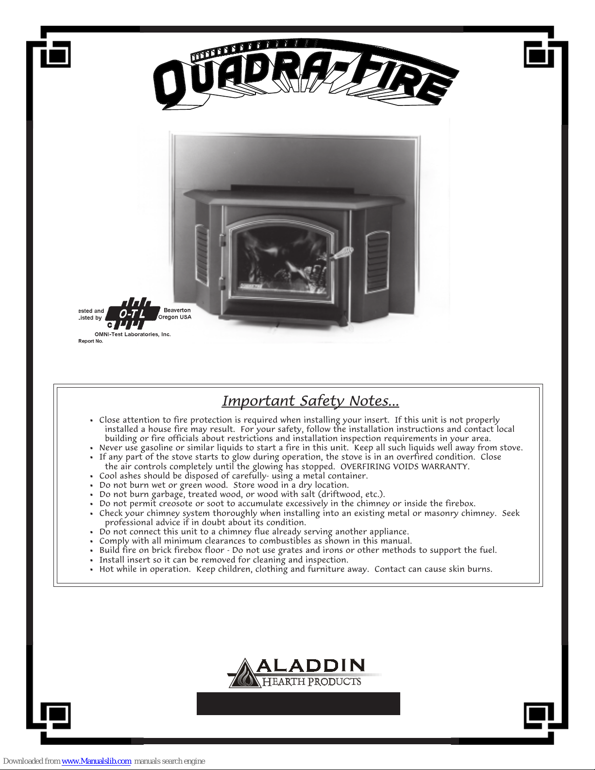
Close attention to fire protection is required when installing your insert. If this unit is not properly
installed a house fire may result. For your safety, follow the installation instructions and contact local
building or fire officials about restrictions and installation inspection requirements in your area.
Never use gasoline or similar liquids to start a fire in this unit. Keep all such liquids well away from stove.
If any part of the stove starts to glow during operation, the stove is in an overfired condition. Close
the air controls completely until the glowing has stopped. OVERFIRING VOIDS WARRANTY.
Cool ashes should be disposed of carefully- using a metal container.
Do not burn wet or green wood. Store wood in a dry location.
Do not burn garbage, treated wood, or wood with salt (driftwood, etc.).
Do not permit creosote or soot to accumulate excessively in the chimney or inside the firebox.
Check your chimney system thoroughly when installing into an existing metal or masonry chimney. Seek
professional advice if in doubt about its condition.
Do not connect this unit to a chimney flue already serving another appliance.
Comply with all minimum clearances to combustibles as shown in this manual.
Build fire on brick firebox floor - Do not use grates and irons or other methods to support the fuel.
Install insert so it can be removed for cleaning and inspection.
Hot while in operation. Keep children, clothing and furniture away. Contact can cause skin burns.
for purchasing one of the finest sto for purchasing one of the finest sto
for purchasing one of the finest sto
for purchasing one of the finest sto for purchasing one of the finest sto
Before proceeding, please record the stoBefore proceeding, please record the sto
Before proceeding, please record the sto
Before proceeding, please record the stoBefore proceeding, please record the sto
401 N. Wynne Street
Colville, WA 99114
WNER’S MANUWNER’S MANU
WNER’S MANU
WNER’S MANUWNER’S MANU
AL AND SAL AND S
AL AND S
AL AND SAL AND S
Important Safety Notes...
Thank yThank y
Thank y
Thank yThank y
vv
e serial number on the enclosed We serial number on the enclosed W
v
e serial number on the enclosed W
vv
e serial number on the enclosed We serial number on the enclosed W
ou,ou,
ou,
ou,ou,
vv
es in the wes in the w
v
es in the w
vv
es in the wes in the w
orld for yorld for y
orld for y
orld for yorld for y
SAVE THESE INSTRUCTIONS
#832-0520 Revised 03/1999
AFETY NOAFETY NO
AFETY NO
AFETY NOAFETY NO
our homeour home
our home
our homeour home
..
.
..
arranty Card.arranty Card.
arranty Card.
arranty Card.arranty Card.
www.aladdinhearth.com
aladdin@aladdinhearth.com
TES.TES.
TES.
TES.TES.
Page 2
2100-I & 3100-I FIREPLACE INSERT
9
9
9
9
9
9
9
9
9
9
9
9
9
9
9
9
9
9
9
9
9
9
9
9
9
9
9
9
9
9
9
9
9
9
9
9
9
9
9
9
9
9
9
9
9
9
9
9
9
9
9
9
9
9
9
9
9
9
9
9
9
9
NOTES
MODEL PURCHASED:
SERIAL NUMBER:
DATE PURCHASED:
DEALERSHIP WHERE PURCHASED:
DEALER PHONE NUMBER
________________________________________________________________
________________________________________________________________
________________________________________________________________
ATTACH YOUR SALES RECEIPT AND WARRANTY STUB HERE:
2345678901234567890123456789012123456789012345678901234567890121234567890123456789012345678901212345678
2345678901234567890123456789012123456789012345678901234567890121234567890123456789012345678901212345678
2345678901234567890123456789012123456789012345678901234567890121234567890123456789012345678901212345678
2345678901234567890123456789012123456789012345678901234567890121234567890123456789012345678901212345678
2345678901234567890123456789012123456789012345678901234567890121234567890123456789012345678901212345678
2345678901234567890123456789012123456789012345678901234567890121234567890123456789012345678901212345678
2345678901234567890123456789012123456789012345678901234567890121234567890123456789012345678901212345678
2345678901234567890123456789012123456789012345678901234567890121234567890123456789012345678901212345678
2345678901234567890123456789012123456789012345678901234567890121234567890123456789012345678901212345678
2345678901234567890123456789012123456789012345678901234567890121234567890123456789012345678901212345678
2345678901234567890123456789012123456789012345678901234567890121234567890123456789012345678901212345678
2345678901234567890123456789012123456789012345678901234567890121234567890123456789012345678901212345678
2345678901234567890123456789012123456789012345678901234567890121234567890123456789012345678901212345678
2345678901234567890123456789012123456789012345678901234567890121234567890123456789012345678901212345678
2345678901234567890123456789012123456789012345678901234567890121234567890123456789012345678901212345678
2345678901234567890123456789012123456789012345678901234567890121234567890123456789012345678901212345678
2345678901234567890123456789012123456789012345678901234567890121234567890123456789012345678901212345678
2345678901234567890123456789012123456789012345678901234567890121234567890123456789012345678901212345678
2345678901234567890123456789012123456789012345678901234567890121234567890123456789012345678901212345678
2345678901234567890123456789012123456789012345678901234567890121234567890123456789012345678901212345678
2345678901234567890123456789012123456789012345678901234567890121234567890123456789012345678901212345678
2345678901234567890123456789012123456789012345678901234567890121234567890123456789012345678901212345678
2345678901234567890123456789012123456789012345678901234567890121234567890123456789012345678901212345678
2345678901234567890123456789012123456789012345678901234567890121234567890123456789012345678901212345678
2345678901234567890123456789012123456789012345678901234567890121234567890123456789012345678901212345678
2345678901234567890123456789012123456789012345678901234567890121234567890123456789012345678901212345678
2345678901234567890123456789012123456789012345678901234567890121234567890123456789012345678901212345678
2345678901234567890123456789012123456789012345678901234567890121234567890123456789012345678901212345678
2345678901234567890123456789012123456789012345678901234567890121234567890123456789012345678901212345678
2345678901234567890123456789012123456789012345678901234567890121234567890123456789012345678901212345678
2345678901234567890123456789012123456789012345678901234567890121234567890123456789012345678901212345678
2345678901234567890123456789012123456789012345678901234567890121234567890123456789012345678901212345678
2345678901234567890123456789012123456789012345678901234567890121234567890123456789012345678901212345678
2345678901234567890123456789012123456789012345678901234567890121234567890123456789012345678901212345678
2345678901234567890123456789012123456789012345678901234567890121234567890123456789012345678901212345678
2345678901234567890123456789012123456789012345678901234567890121234567890123456789012345678901212345678
2345678901234567890123456789012123456789012345678901234567890121234567890123456789012345678901212345678
2345678901234567890123456789012123456789012345678901234567890121234567890123456789012345678901212345678
2345678901234567890123456789012123456789012345678901234567890121234567890123456789012345678901212345678
2345678901234567890123456789012123456789012345678901234567890121234567890123456789012345678901212345678
2345678901234567890123456789012123456789012345678901234567890121234567890123456789012345678901212345678
2345678901234567890123456789012123456789012345678901234567890121234567890123456789012345678901212345678
2345678901234567890123456789012123456789012345678901234567890121234567890123456789012345678901212345678
2345678901234567890123456789012123456789012345678901234567890121234567890123456789012345678901212345678
2345678901234567890123456789012123456789012345678901234567890121234567890123456789012345678901212345678
2345678901234567890123456789012123456789012345678901234567890121234567890123456789012345678901212345678
2345678901234567890123456789012123456789012345678901234567890121234567890123456789012345678901212345678
2345678901234567890123456789012123456789012345678901234567890121234567890123456789012345678901212345678
2345678901234567890123456789012123456789012345678901234567890121234567890123456789012345678901212345678
2345678901234567890123456789012123456789012345678901234567890121234567890123456789012345678901212345678
2345678901234567890123456789012123456789012345678901234567890121234567890123456789012345678901212345678
2345678901234567890123456789012123456789012345678901234567890121234567890123456789012345678901212345678
2345678901234567890123456789012123456789012345678901234567890121234567890123456789012345678901212345678
NOTES & SYMBOLS
Page 2
2345678901234567890123456789012123456789012345678901234567890121234567890123456789012345678901212345678
2345678901234567890123456789012123456789012345678901234567890121234567890123456789012345678901212345678
2345678901234567890123456789012123456789012345678901234567890121234567890123456789012345678901212345678
2345678901234567890123456789012123456789012345678901234567890121234567890123456789012345678901212345678
2345678901234567890123456789012123456789012345678901234567890121234567890123456789012345678901212345678
2345678901234567890123456789012123456789012345678901234567890121234567890123456789012345678901212345678
2345678901234567890123456789012123456789012345678901234567890121234567890123456789012345678901212345678
2345678901234567890123456789012123456789012345678901234567890121234567890123456789012345678901212345678
2345678901234567890123456789012123456789012345678901234567890121234567890123456789012345678901212345678
ADDITIONAL INFORMATION :
Quick Reference Symbols
OPERATING TIPS & PROCEDURES
CAUTION AND WARNING !
INSTALLATION INSTRUCTIONS
CLEANING & MAINTENANCE TIPS
IMPORTANT REMINDERS
March 1999
Page 3

2100-I & 3100-I FIREPLACE INSERT
TABLE OF CONTENTS
Welcome ........................................................................................... 4
Dimensions ........................................................................................... 5
Safety Labels ......................................................................................... 6
Component Parts Diagram .................................................................... 8
Clearances to Combustibles .................................................................. 9
Hearth Requirements ............................................................................. 9
INSTALLATION
Recommendations ............................................................. 10
Canadian ........................................................................... 10
General Procedures Listing ............................................... 11
Unpacking/Use of Leveling Bolts..................................... 11
Blower Assembly .............................................................. 12
Panel Set............................................................................ 13
Face Trim .......................................................................... 13
Door Handle ...................................................................... 13
Chimney Requirements..................................................... 14
MASONRY FIREPLACE ................................................ 16
METAL HEAT EXCHANGER ........................................ 18
FACTORY BUILT FIREPLACE (Zero Clearance) ......... 18
OPERATION
Wood Selection ................................................................. 20
Overfiring.......................................................................... 20
Building a fire ................................................................... 20
Obtaining Burn Rates........................................................ 21
Fan Operation.................................................................... 22
MAINTENANCE
Gold Plated Surfaces ......................................................... 22
Glass.................................................................................. 22
Glass Replacement ............................................................ 22
Chimney ............................................................................ 23
Ash Removal..................................................................... 23
Firebrick ............................................................................ 23
Baffle Removal & Installation............................................................... 24
Air Quality and the Quadra-Fire Insert.................................................. 26
Warranty ........................................................................................... 27
CONTENTS
Page 3 March 1999
Page 4
2100-I & 3100-I FIREPLACE INSERT
WELCOME !
Aladdin Hearth Products welcomes you to our tradition of excellence! In choosing a Quadra-Fire
appliance, you have our assurance of commitment to quality, durability, and performance.
This commitment begins with our research of the market, including ‘Voice of the Customer’
contacts, ensuring we make products that will satisfy your needs. Our Research and Development
facility then employs the world’s most advanced technology to achieve the optimum operation of
our stoves, inserts and fireplaces. And yet we are old-fashioned when it comes to craftsmanship.
During manufacturing each unit is meticulously fabricated and gold surfaces are hand-finished for
lasting beauty and enjoyment. Our pledge to quality is completed as each model undergoes a
quality control inspection. Additionally, we feel it is important to offer you several finishing options and accessories to compliment your home’s décor, individualize the use of your appliance, and
provide financial options in acquiring a quality hearth appliance. Ask your Quadra-Fire Dealer for
information on these options. From design, to fabrication, to shipping: Our guarantee of quality is
more than a word, it’s Quadra-Fire tradition, and we proudly back this tradition with a Lifetime
Warranty.
Prior to installation, we ask you to take a few moments to read this manual. It has been our experience that your overall enjoyment of your new appliance will be greatly enhanced by becoming
familiar with its’ installation, operation and maintenance requirements. We wish you and your
family many years of enjoyment in the warmth and comfort of your hearth appliance. Thank you
for choosing Quadra-Fire.
With warm regards,
President V.P. Research & Development
Controller Operations Manager V.P. Sales & Marketing
Western Sales Manager Central Sales Manager Eastern Sales Manager
WELCOME
Manufacturing Eng. Manager Sr. Purchasing Agent Technical Support Manager
Customer Support Manager Human Resources Supervisor
Manager
Page 4
3100-I, shown with optional gold accent door and gold accent louvered sides
March 1999
Page 5
2100-I & 3100-I FIREPLACE INSERT
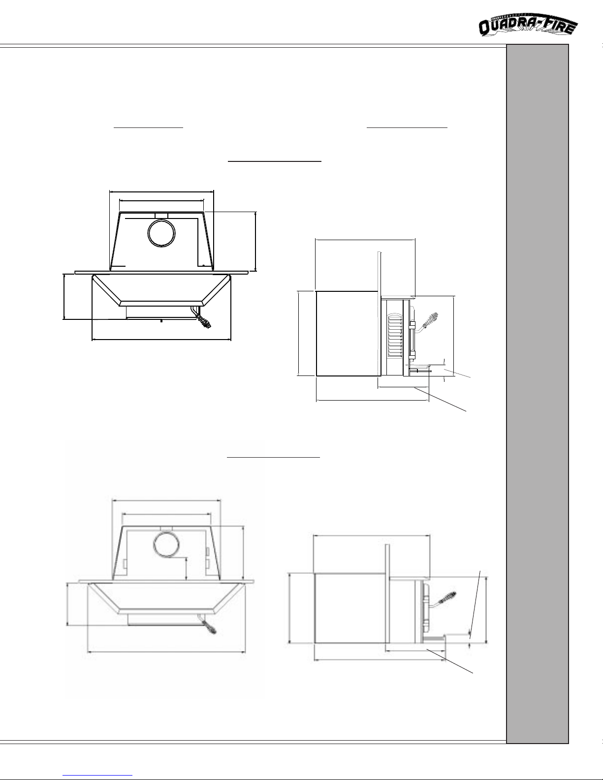
DIMENSIONS
MODEL 2100-I
SIDE VIEWTOP VIEW
10 15/16 (279 mm)
25 1/16 (637 mm)
20 1/4 (514 mm)
33 7/16 (850 mm)
14 1/14 (362 mm)
19 7/16 (495 mm)
MODEL 3100-I
DIMENSIONS
22 3/4 (578 mm)
18 3/8 (468 mm)
2 11/16 (69 mm)
25 3/4 (654 mm)
11 11/16 (297 mm)
27 1/4 (698 mm)
22 3/8 (583 mm)
5 3/4
10 15/16 (279 mm)
39 7/8 (1012 mm)
22 3/4 (576 mm)
2 11/16 (43 mm)
(152 mm)
13 13/16 (354 mm)
21 7/16 (546 mm)
25 9/16 (650 mm)
11 11/16 (295 mm)
20 7/16 (519 mm)
Page 5 March 1999
Page 6
2100-I & 3100-I FIREPLACE INSERT
2
2
2
2
2
2
2
2
2
2
2
2
2
2
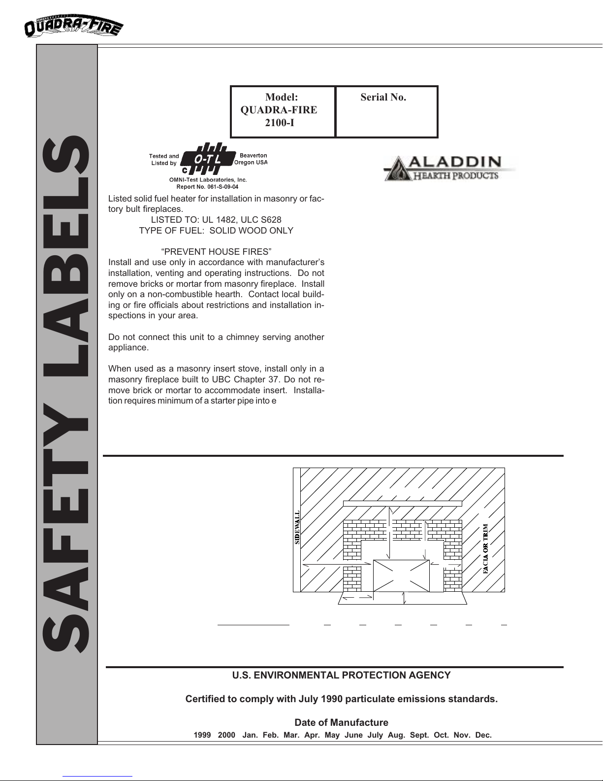
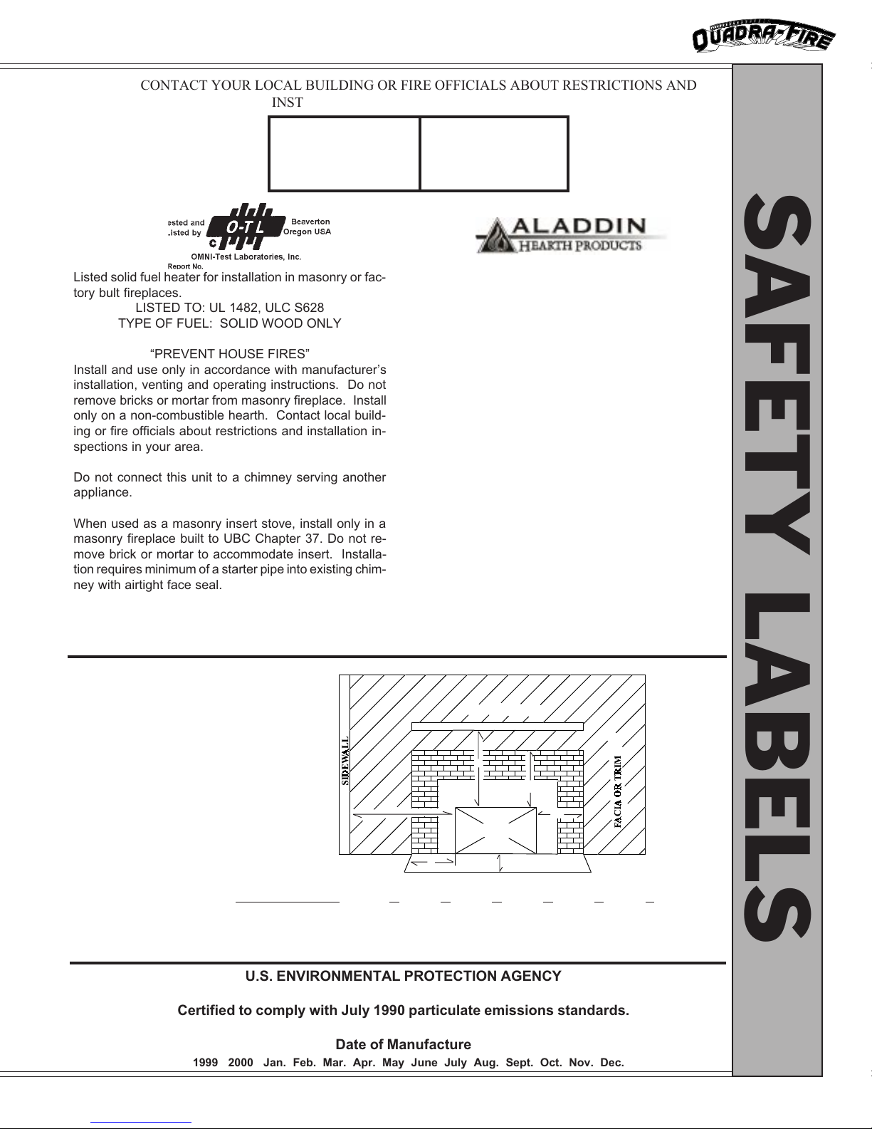
CONTACT YOUR LOCAL BUILDING OR FIRE OFFICIALS ABOUT RESTRICTIONS AND
INSTALLATION INSPECTION IN YOUR AREA
23456789012345678901234567890121234567890123456789012345678901
23456789012345678901234567890121234567890123456789012345678901
23456789012345678901234567890121234567890123456789012345678901
23456789012345678901234567890121234567890123456789012345678901
Model: Serial No.
23456789012345678901234567890121234567890123456789012345678901
23456789012345678901234567890121234567890123456789012345678901
23456789012345678901234567890121234567890123456789012345678901
23456789012345678901234567890121234567890123456789012345678901
QUADRA-FIRE
23456789012345678901234567890121234567890123456789012345678901
23456789012345678901234567890121234567890123456789012345678901
23456789012345678901234567890121234567890123456789012345678901
23456789012345678901234567890121234567890123456789012345678901
2100-I
23456789012345678901234567890121234567890123456789012345678901
23456789012345678901234567890121234567890123456789012345678901
MANUFACTURED BY:
Listed solid fuel heater for installation in masonry or factory bult fireplaces.
LISTED TO: UL 1482, ULC S628
TYPE OF FUEL: SOLID WOOD ONLY
PREVENT HOUSE FIRES
Install and use only in accordance with manufacturers
installation, venting and operating instructions. Do not
remove bricks or mortar from masonry fireplace. Install
only on a non-combustible hearth. Contact local building or fire officials about restrictions and installation inspections in your area.
Do not connect this unit to a chimney serving another
appliance.
When used as a masonry insert stove, install only in a
masonry fireplace built to UBC Chapter 37. Do not remove brick or mortar to accommodate insert. Installation requires minimum of a starter pipe into existing chimney with an airtight face seal.
Operate only with doors closed. Replace glass only
with 5mm ceramic available from your dealer.
Minimum Clearances to Combustible Materials (in inches)
Approved for installation and use in factory built zeroclearance fireplaces conforming to minimum fire
chamber specifications.
Components required for installation: positive or direct
flue connection assembly or listed vent liner. Inspect
and clean vent system frequently in accordance with
manufacturers instructions.
In Canada a full length S635 flue liner is required.
For use with solid wood fuel only. Do not use grate or
elevate fire. Build wood fire directly on hearth.
Route power cord away from unit. Do not route cord
over or under appliance.
DANGER: Risk of electrical shock. Disconnect power
supply before servicing.
Optional component:
Blower Assembly: Part #831-0911
Electrical Rating:
115 VAC, .6 Amps, 60 Hz.
MANTEL
Install insert with a mimimum of
26 clearance to combustible
sidewall, 10 to side and 14 to top
trim, 22 from top of insert to mantel. Floor protector must be 3/8
mimimum non-combustible material or equivalent, extending 16 in
front and 8 to both sides.
SAFETY LABELS
Certified to comply with July 1990 particulate emissions standards.
1999 2000 Jan. Feb. Mar. Apr. May June July Aug. Sept. Oct. Nov. Dec.
Page 6
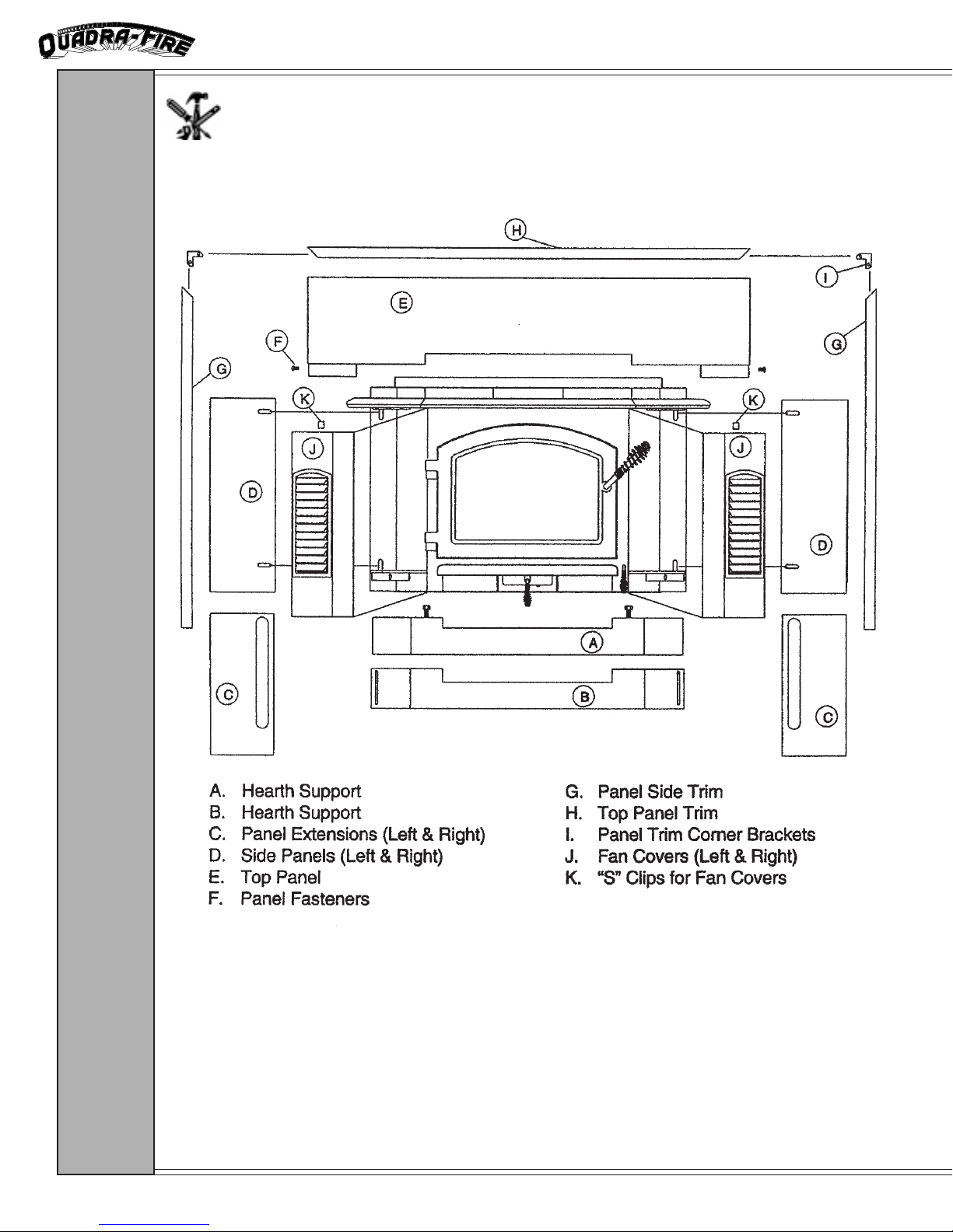
B
C
A
D
INSERT
F
HEARTH EXTENSION
E
INSTALLATION A B C D E F
UNITED STATES 26 22 14 10 16 8
CANADA 32 27 14 12 16 8
815mm 685mm 355mm 305mm 405mm 200mm
U.S. ENVIRONMENTAL PROTECTION AGENCY
Date of Manufacture
March 1999
Page 7
2100-I & 3100-I FIREPLACE INSERT
1
1
1
1
1
1
1
1
1
1
1
1
1
1
1
CONTACT YOUR LOCAL BUILDING OR FIRE OFFICIALS ABOUT RESTRICTIONS AND
INSTALLATION INSPECTION IN YOUR AREA
2345678901234567890123456789012123456789012345678901234567890
2345678901234567890123456789012123456789012345678901234567890
2345678901234567890123456789012123456789012345678901234567890
2345678901234567890123456789012123456789012345678901234567890
2345678901234567890123456789012123456789012345678901234567890
Model: Serial No.
2345678901234567890123456789012123456789012345678901234567890
2345678901234567890123456789012123456789012345678901234567890
2345678901234567890123456789012123456789012345678901234567890
2345678901234567890123456789012123456789012345678901234567890
QUADRA-FIRE
2345678901234567890123456789012123456789012345678901234567890
2345678901234567890123456789012123456789012345678901234567890
2345678901234567890123456789012123456789012345678901234567890
2345678901234567890123456789012123456789012345678901234567890
3100-I
2345678901234567890123456789012123456789012345678901234567890
2345678901234567890123456789012123456789012345678901234567890
MANUFACTURED BY:
SAFETY LABELS
Listed solid fuel heater for installation in masonry or factory bult fireplaces.
LISTED TO: UL 1482, ULC S628
TYPE OF FUEL: SOLID WOOD ONLY
PREVENT HOUSE FIRES
Install and use only in accordance with manufacturers
installation, venting and operating instructions. Do not
remove bricks or mortar from masonry fireplace. Install
only on a non-combustible hearth. Contact local building or fire officials about restrictions and installation inspections in your area.
Do not connect this unit to a chimney serving another
appliance.
When used as a masonry insert stove, install only in a
masonry fireplace built to UBC Chapter 37. Do not remove brick or mortar to accommodate insert. Installation requires minimum of a starter pipe into existing chimney with airtight face seal.
Operate only with doors closed. Replace glass only with
5mm ceramic available from your dealer.
Minimum Clearances to Combustible Materials (in inches)
Install insert with a mimimum of
32 clearance to combustible
sidewall, 10 to side and 14 to top
trim, 22 from top of insert to mantel. Floor protector must be 3/8
mimimum non-combustible material or equivalent, extending 16 in
front and 8 to both sides.
Approved for installation and use in factory built zeroclearance fireplaces conforming to minimum fire
chamber specifications.
Components required for installation: positive or direct
flue connection assembly or listed vent liner. Inspect
and clean vent system frequently in accordance with
manufacturers instructions.
In Canada a full length S635 flue liner is required.
For use with solid wood fuel only. Do not use grate or
elevate fire. Build wood fire directly on hearth.
Route power cord away from unit. Do not route cord
over or under appliance.
DANGER: Risk of electrical shock. Disconnect power
supply before servicing.
Optional component:
Blower Assembly: Part #831-1101
Electrical Rating:
115 VAC, .6 Amps, 60 Hz.
MANTEL
B
C
A
D
INSERT
INSTALLATION A B C D E F
UNITED STATES 32 22 14 10 16 8
CANADA 32 27 14 12 16 8
U.S. ENVIRONMENTAL PROTECTION AGENCY
Certified to comply with July 1990 particulate emissions standards.
1999 2000 Jan. Feb. Mar. Apr. May June July Aug. Sept. Oct. Nov. Dec.
Date of Manufacture
F
HEARTH EXTENSION
E
815mm 685mm 355mm 305mm 405mm 200mm
Page 7 March 1999
Page 8
2100-I & 3100-I FIREPLACE INSERT
COMPONENT PARTS DIAGRAM
COMPONENTS
Page 8
March 1999
Page 9
2100-I & 3100-I FIREPLACE INSERT
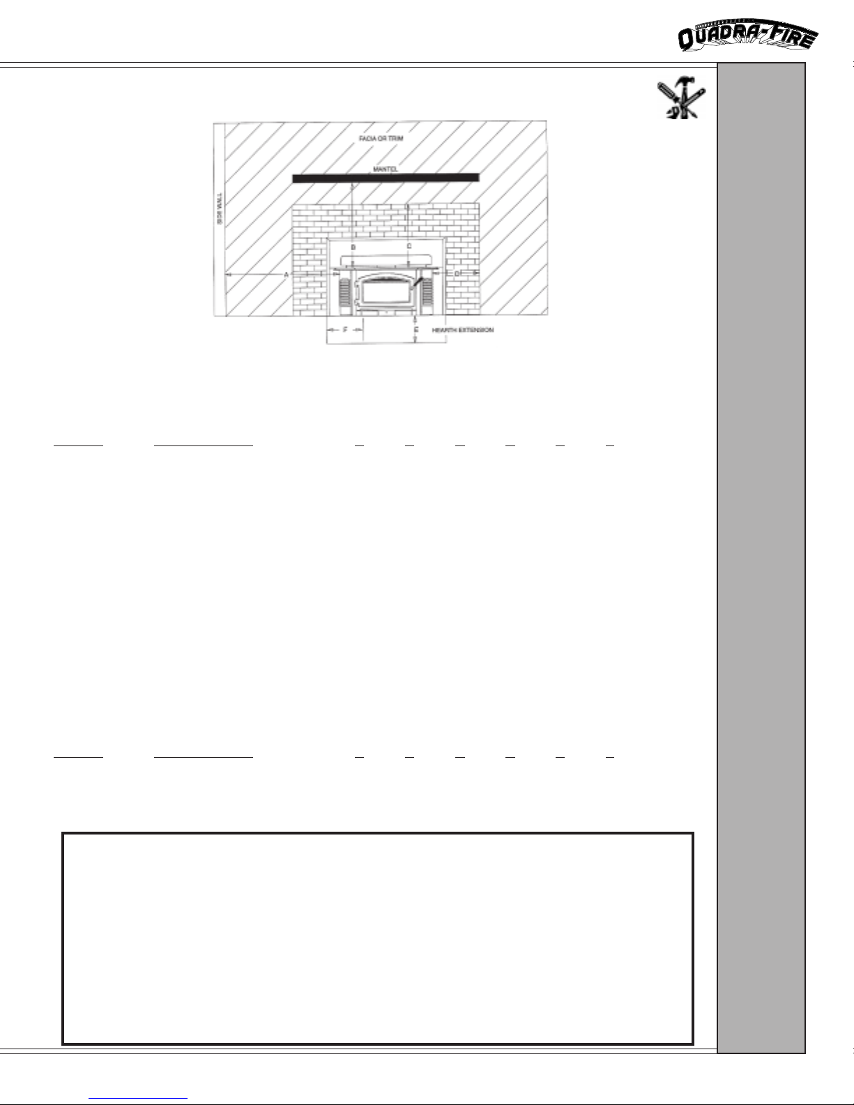
CLEARANCES TO COMBUSTIBLES
UNITED STATES INSTALLATION
MINIMUM CLEARANCES TO COMBUSTIBLES IN INCHES
MODEL INSTALLATION A B C D E F
2100-I Masonry or Heat Exchanger 26 22 14 10 16 8
Zero Clearance 26 22 14 10 16 8
3100-I Masonry or Heat Exchanger 32 22 14 10 16 8
Zero Clearance 32 22 14 10 16 8
CLEARANCES
NOTE: When installing into a masonry fireplace, the fireplace must be built to UBC Chapter 37
standards. Do not remove brick or mortar from masonry fireplace to accommodate insert.The
permanent metal warning plate label provided must be attached to the back of the fireplace stating the fireplace may have been altered to accomodate the insert and must be returned to original
condition for use as a conventional fireplace.
INSTALLATION IN CANADA
MINIMUM CLEARANCES TO COMBUSTIBLES
IN INCHES & MILLIMETERS
MODEL INSTALLATION A B C D E F
2100-I Masonry or Heat Exchanger 32 27 14 12 16 8
815mm 685mm 355mm 305mm 405mm 200mm
3100-I Masonry or Heat Exchanger 32 27 14 12 16 8
815mm 685mm 355mm 305mm 405mm 200mm
HEARTH REQUIREMENTS
There must be 3/8 minimum non-combustible material or equivalent extending 16 in
front of insert and 8 to both sides. If the hearth extension is lower than the fireplace
opening, the portion of the insert extending onto the hearth requires support. Manufacturer support kits can be ordered by the necessary adjustment size.
ADJUSTMENT 2100-I PART # 3100-I PART #
2 - 4 831-1370 831-1400
4 - 7 831-1380 831-1410
7 - 10 831-1390 831-1420
Page 9 March 1999
Page 10

2100-I & 3100-I FIREPLACE INSERT
INSTALLATION RECOMMENDATIONS
The Quadra-Fire 2100-I and 3100-I have met and surpassed the most stringent emissions
standards in the United States. The sophistication of the interior firebox design requires that a
proper draft be supplied by the chimney, therefore adherance to the following factors will enable
your stove to operate at its optimum capability:
REQUIRED
A minimum starter pipe reaching to the base of the existing chimney and an airtight face seal.
BETTER
Direct connection to the first flue liner in accordance with the requirements of the NFPA 211.
BEST
A complete relining of the chimney system with a six inch (6) diameter listed, stainless liner.
INSTALLATION IN CANADA
MASONRY, HEAT-EXCHANGER & FACTORY-BUILT
Whether installed in a masonry, heat-exchanger or factory-built fireplace, a
full chimney liner meeting ULC S635, CLASS III (stainless steel) must be
installed from the insert to the chimney top and securely attached to both.
Do not remove bricks or mortar from fireplace to accommodate insert.
The permanent metal warning label provided must be affixed to the back of
the fireplace stating that the fireplace may have been altered to accommodate the insert, and must be returned to original condition for use as a
conventional fireplace.
INSTALLATION
The face of the fireplace must be sealed to prevent room air passage into the
chimney cavity.
Circulating air chambers in factory-built fireplaces may not be blocked.
FIREPLACES
Page 10
March 1999
Page 11

2100-I & 3100-I FIREPLACE INSERT
GENERAL INSTALLATION PROCEDURE
Install liner, if required, for your chosen installation.
Attach metal warning plate to the back of the fireplace.
Set appliance on the hearth (See Hearth Requirements and Support Kits
information on page 9.)
Complete the vent connection required for your installation type.
Install optional blower, if purchased.
Install panel set. (See instructions on page 13)
Install trim. (See instructions on page 13)
Position unit into fireplace leaving width enough for fiberglass batt to be
inserted around face seal.
Work unit securely into the fireplace.
Install door handle. (See instructions on page 13)
Ensure that all labels are removed from glass prior to building first fire.
Ensure that gold plated surfaces are cleaned prior to building first fire.
(See instructions on page 22)
Read Operation Instructions found on pages 20-22.
INSTALLATION
UNPACKING AND USE OF LEVELING BOLTS
Your Quadra-Fire insert is secured to the pallet by means of two 1/2 x 6 bolts which
also serve as leveling bolts in the event that the hearth is higher than the fireplace floor. Follow
the procedures below for moving the insert from the pallet and use of the leveling bolts.
1. Remove 1/2 nuts from 1/2 x 6 bolts.
2. Bring 1/2 bolts up level to bottom of insert.
3. Position insert on hearth with rear of insert extending into fireplace opening.
4. Extend leveling bolts downward to level insert.
5. Make proper connection for desired venting technique.
Page 11 March 1999
Page 12

Available through your Quadra-Fire Dealer: Order Part #831-0911 for model 2100-I
BLOWER
ASSEMBLY
:
Tools Needed:
Large Phillips screwdriver
Pliers
2100-I & 3100-I FIREPLACE INSERT
BLOWER ASSEMBLY
(OPTIONAL PURCHASE ACCESSORY)
Order Part #831-1101 for model 3100-I
Parts Supplied: (2) Fan mounts/fan assemblies. (1) speed control, power cord/wire assembly.
(1 Set) Fan connector wires, must be high temperature wire. (1) Strain relief.
1. Remove fan covers.
2. Install fan mounts to outer wall with panel mounting screws.
3. Feed fan and motor wires up through large hole in floor.
NOTE: Power cord can be mounted on left or right side.
4. Connect white and black wires to fan motor terminals.
5. Feed #3 fan motor wires through smaller hole in bottom and across
to #2 fan motor.
6. Install strain relief onto power cord.
7. Using a pair of pliers, squeeze strain relief and push through large
hole in floor.
8. Plug in and test blower operation.
9. Replace screens. (Power cord comes out through opening in
bottom of screen.)
The blower speed control is pre-set at the factory. However, if you determine that an adjustment
is needed, follow these steps:
1. With the unit plugged in, turn the speed control knob to slow.
(Full clockwise.)
2. Use a small screwdriver to adjust the fan speed by turning the adjustment mechanism through the hole on the side of the speed control.
3. Adjust the speed so the fan runs slowly but does not stop. Turn clockwise to slow the fan and counterclockwise to increase the speed.
INSTALLATION
Page 12
March 1999
Page 13

2100-I & 3100-I FIREPLACE INSERT
INSTALLATION OF PANEL SET
Materials needed: Phillips Screwdriver and double sided tape or contact adhesive.
1. Remove four 1/4 - 20 screws from nuts attached to insert outer wall.
2. Slide side panels in front on insert outer wall, align horizontal and
vertical slots and install 1/4 - 20 screws (do not tighten).
3. Remove two 1/4 - 20 screws from top panel.
4. Attach top panel by means of two clips welded on the back side of panel.
5. Insert two 1/4 - 20 screws through holes in outer edges of side panels
into nuts welded inside top panel. Tighten.
6. Center the panels and tighten screws holding side panels.
7. Install screen covers.
8. Attach insulation strip to the outside edge of the backside of top and side
panels. Use double sided tape or a contact adhesive to hold insulation in
place.
INSTALLATION OF FACE TRIM PACKAGE
INSTALLATION:
(For use with part # 831-1150, Black Side Screens Only)
(TOP VIEW)
FIREBOX
PANEL
Press fit the trim between
face and decorative screen.
FAN
FACE
INSTALLATION OF DOOR HANDLE
DOOR HANDLE ASSEMBLY
SPRING HANDLE
PANEL, TRIM &
DOOR HANDLE
NOTE: SPRING HANDLE IS NOT
INCLUDED IN ASSEMBLY. MUST
BE ORDERED SEPARATELY.
SPRING HANDLE ORDER #832-0620
DOOR HANDLE
DOOR
KEY
WASHERS
LATCH CAM
NUT
Page 13 March 1999
Page 14

2100-I & 3100-I FIREPLACE INSERT
CHIMNEY REQUIREMENTS
To insure that insulation or any other combustible material does not contact the chimney,
a chimney inside the house must have at least two (2) inches of air space clearance around the
chimney. A chimney outside the house must have at least one (1) inch clearance to the combustible structure. Fire stops must be installed at the spaces where the chimney passes through floors
and/or ceilings. Refer to Figures 1 & 2 below. Canadian installations require a full re-line of
the chimney.
FIGURE 1
MINIMUM 1 INCH CLEARANCE
FROM EXTERIOR CHIMNEY TO
SHEATHING
FLOOR
(SECOND STORY)
MINIMUM 2 INCH CLEARANCE FROM
COMBUSTIBLE MATERIAL AND
INSULATION
NONCOMBUSTIBLE
FIRESTOPPING
MATERIAL
Firestopping
FLOOR
CEILING
CAULK
FIGURE 2
CHIMNEY
Page 14
CEILING
NONCOMBUSTIBLE FIRE-
STOPPING MATERIAL
March 1999
Page 15

2100-I & 3100-I FIREPLACE INSERT
A chimney must be the required height above the roof or other obstruction for safety
and for proper draft operation. The requirement is that the chimney must be at least three (3)
feet higher than the highest point where it passes through the roof, and at least two (2) feet
higher than the highest part of the roof or structure that is within ten (10) feet of the chimney,
measured horizontally. Refer to Figure 3 below.
FIGURE 3
AT
LEAST 2
AT LEAST
3 FEET
FEET
10 FEET
CHIMNEY
FIGURE 4
CHIMNEY HEIGHT
5/8 FIRECLAY
FLUE LINER
FLUE
CHIMNEY
WALL 4
(NOMINAL)
1/2 AIRSPACE
FOUNDATION
CHIMNEY TOP VIEW
Page 15 March 1999
Page 16

2100-I & 3100-I FIREPLACE INSERT
INSTALLATION OPTIONS
Please refer to:
Clearances to Combustibles on page 9.
Canadian Installation requirements on page 9 & 10.
Hearth Requirements and Support Kits on page 9.
MASONRY
FIREPLACE
:
1482 in all respects, and are approved to UL safety standards for installation and use within a
fireplace with a masonry chamber in accordance with NFPA No. 211, with or without a direct
flue collar connection. A starter pipe is required to reach to the bottom of the existing flue.
The Quadra-Fire 2100-I and 3100-I models conform with the UL Standard for Safety
1. Secure the fireplace damper in the open position. If this cannot be
2. Seal either the damper area around the chimney liner with a high
3. The chimney should be examined for cracks, loose mortar, and other
MASONRY FIREPLACE
USING DIRECT-CONNECT METHOD
accomplished, it will be necessary to remove the damper.
temperature sealant or the fireplace front with fiberglass batting.
signs of deterioration and blockage. The insert should not be installed
until it is determined that the chimney is safe for use. Since an oversized flue contributes to the accumulation of creosote, the size of the
flue should be checked to determine that it is not too large for the
insert. The chimney should also be checked to assure it meets the
minimum standard of the National Fire Protection Association
(NFPA) Standard 211. The following bullets list the more critical
requirements for a properly constructed chimney:
The masonry wall of the chimney, if brick or modular block, must be a
minimum of four (4) inches nominal thickness. A chimney of rubble
stone must be at least twelve (12) inches thick.
The chimney must have a fire clay flue liner (or equivalent) with a
minimum thickness of 5/8 and must be installed with refractory
mortar. An equivalent liner must be a listed chimney liner system or
other approved material.
A chimney inside the house must have at least two (2) inches of
clearance to the combustible structure. A chimney outside the house
must have at least one inch clearance to the combustible structure.
Fire stops must be installed at the spaces where the chimney passes
through floors and/or ceiling (See Figure 1 on page 14). In Canada,
a full reline is required.
INSTALLATION
Page 16
March 1999
Page 17

MASONRY CHIMNEY
FLUE TILE
2100-I & 3100-I FIREPLACE INSERT
INSTALLATION:
MANTEL
AIRTIGHT FACE SEAL
DAMPER AREA
SEAL DAMPER AREA OR FACE SEAL
FULL LISTED
LINER OPTION
DIRECT CONNECT
SEAL OPTION
MINIMUM STARTER
PIPE OPTION
FIREPLACE
MASONRY
SAMPLE INSTALLATION INTO MASONRY FIREPLACE
Page 17 March 1999
Page 18

METAL HEAT EXCHANGER MASONRY
The Quadra-Fire 2100-I and 3100-I models conform with the safety standard UL1482 in all respects and is approved to UL safety standards for installation and use within a
fireplace with masonry chamber, in accordance with NFPA No. 211, with or without a
HEAT
direct flue collar connection. A starter pipe is required into existing chimney.
SAMPLE INSTALLATION INTO METAL HEAT EXCHANGER
EXCHANGER
:
SHOSHO
SHO
SHOSHO
MANTEL
LISTED LINER
2100-I & 3100-I FIREPLACE INSERT
WING USE OF STWING USE OF ST
WING USE OF ST
WING USE OF STWING USE OF ST
ARAR
AR
ARAR
TER PTER P
TER P
TER PTER P
IPIP
IP
IPIP
EE
E
EE
Page 18
SEAL DAMPER AREA OR FACE SEAL
FACTORY BUILT FIREPLACE
(ZERO CLEARANCE)
The Quadra-Fire 2100-I and 3100-I are also listed to UL Standards for Safety 127, and
approved for installation and use in factory built zero clearance fireplaces conforming to the
following specifications:
2100-I 3100-I
Minimum Width of cavity opening: 29 (737mm) 32 (813mm)
Minimum Height: 21 (533mm) 23 (584mm)
Depth of the firebox may vary according to brand name, however the top rear corners of
the insert require a 2 (51mm) space between the insert and the side and back walls of the fireplace unit. Installation into larger sizes of factory built fireplaces of the above-named brands is
permissible.
The following modifications of factory built fireplaces are permissible. 1) Removal of
damper. 2) Removal of smoke shelf or baffle. 3) Removal of ember catches. 4) Removal of fire
INSTALLATION
grate. 5) Removal of viewing screen/curtain. 6) Removal of doors.
March 1999
Page 19

2100-I & 3100-I FIREPLACE INSERT
NOTE: Installation into fireplaces without a permit will void the listing.
The factory built chimney must be listed per UL 127 (US) or ULC S610 (Canada), and
meet the type HT requirements of UL 103 (US) or ULC S629M (Canada). Factory built fireplace
chimneys tested to UL 127-1998 are tested to the same criteria as UL 103 HT requirements. If the
chimney is not listed as meeting HT requirements (factory built fireplaces tested prior to 1988), a
full height listed chimney liner must be installed from the appliance flue collar to the chimney
top. The liner must meet type HT requirements (2100ºF) per UL 1777 (US) or ULC S635 (Canada).
The liner must be securely attached to the insert flue collar and the chimney top. To prevent room
air passage to the chimney cavity of the fireplace, seal either the damper area around the chimney
liner with high temperature sealant or the fireplace front with fiberglass batting.
The fireplace must not be altered, except that the damper may be removed to accommodate a direct-connect starter pipe or chimney liner, and external trim pieces which do not affect
the operation of the fireplace may be removed providing they can be stored on or within the
fireplace for reassembly if the insert is removed. The permanent metal warning label provided
must be attached to the back of the fireplace, stating that the fireplace may have been altered to
accommodate the insert, and must be returned to original condition for use as a conventional
fireplace.
The air flow within and around the fireplace shall not be altered by the installation of the
insert (no louvers or cooling air inlet or outlet ports blocked). The circulating air chambers (in a
steel fireplace liner or metal heat circulator) shall be blocked.
If the hearth extension is lower than the fireplace opening, the portion of the insert extending onto the hearth must be supported. Manufacturer designed support kits can be ordered by size
(see page 9).
Final approval of this installation type is contingent upon the authority having jurisdiction.
INSTALLATION:
MANTEL
LISTED
LINER
SEAL DAMPER AREA OR FACE SEAL
SAMPLE INSTALLATION INTO A FACTORY BUILT FIREPLACE
(ZERO CLEARANCE)
FACTORY BUILT
FIREPLACE
Page 19 March 1999
Page 20

2100-I & 3100-I FIREPLACE INSERT
OPERATION
WOOD SELECTION AND STORAGE
Burn only dry seasoned wood. Dry, well-seasoned wood will not only minimize the
chance of creosote formation but will give you the most efficient heat output. Even dry wood
contains at least 15% moisture by weight and should be burned hot enough to keep the chimney
high enough to maintain particulate (smoke) burning. Burning unseasoned wood of any variety
defeats the stoves efficiency.
Dead wood lying on the forest floor should be considered wet, and requires full seasoning
time. Standing wood can be considered to be about two-thirds seasoned. Wood is dry enough to
burn if the ends of the logs have cracks radiating in all directions from the center. If your wood
sizzles in the fire, even though the surface is dry, it may not be fully cured.
Drying time can be reduced by splitting wood prior to storage. Since the majority of
drying occurs through the cut ends rather than the sides, stack the wood so both ends of each piece
are exposed to air. Store wood under cover, such as in a shed, or covered with a tarp, plastic,
tarpaper, sheets of scrap plywood, etc.
OVERFIRING
Do not overfire. Overfiring can result in crazing, an effect causing a white, non-removable film to be deposited on the inside of the glass. Using flammable liquids or too much wood,
or burning trash in the insert, may result in overfiring. If the chimney connector or insert glows
red, or worse, white, the insert is overfired. This condition may ignite creosote in the chimney,
possibly causing a house fire. If any part of the insert starts to glow, you are in an overfire
situation. If you overfire, immediately close the insert dampers and door, if open, to reduce the air
supply to the fire. Overfiring your insert voids your warranty.
BUILDING A FIRE
NOTE: Remove all labels from glass front prior to lighting the first fire.
There are many ways to build a fire. The basic principle is to light easily ignitable tinder
or paper, which ignites the fast-burning kindling, which in turn ignites the slow burning firewood. Here is one method that works well:
1. Ensure that no matches or other combustibles are in the immediate area of the insert, that the
room is adequately ventilated, and the flue is unobstructed.
OPERATION
2. Open primary and secondary air controls fully.
3. Place several wads of crushed paper on the firebox floor.
4. Lay small dry sticks of kindling on top.
5. Light the wadded paper in the insert. Never light or rekindle insert with kerosene, gasoline,
or charcoal lighter fluid; results can be fatal.
6. Once kindling is burning quickly, add several full length logs three or four inches in diameter. Be careful not to smother the fire. Stack the pieces of wood carefully, near enough to
keep each other hot, but far enough away to allow adequate air flow between them. Large logs
burn slowly, holding a fire longer. Small logs burn fast and hot, giving quick heat.
7. Adjust the primary and secondary air controls, maintaining flames above the fuel. The
more you close down the controls, the lower and slower the fire will burn. The more you open
Page 20
March 1999
Page 21

2100-I & 3100-I FIREPLACE INSERT
the controls the more heat will be produced. Remember: PUSH IN air controls to OPEN for
ventilation, PULL OUT air controls to CLOSE ventilation.
As long as there are hot coals, repeating steps 6 and 7 will maintain a continuous fire.
NOTE: The special high temperature finish paint applied to the insert will cure as your insert
heats. You will notice an odor and perhaps see some vapor rise from the insert surface, this is
normal. We recommend that you open a window until the odor dissipates and the paint is
cured.
OPERATING TIPS
1. When loading the insert leave both controls open until the new wood load is burning well
enough to maintain flames above the fuel.
2. Regulate the heat output by using the secondary air control (located in the center of the insert
under the ash catcher). The primary air control, on the right of insert, is mainly for initial startup, reloading, or high burns.
3. Heat output settings: To obtain the following desired heat output setting, first follow step 1,
above. Then follow the Primary and Secondary air control openings as described below:
HIGH BURN RATE
Fully open both controls by pushing in completely. It is especially important to fully
open both controls when reloading the insert as failure to do so could result in excessive emissions, also referred to as opacity.
OPERATION
MEDIUM BURN RATE
After a wood load has been burning on high for 5 to 15 minutes, or longer for very large
pieces, close the primary air control (located on the right side of the insert) by pulling it out.
Leave the secondary air control (under the ash catcher) open (pushed in).
LOW BURN RATE
After a wood load has been burning on high for 5 to 15 minutes, or longer for very large
pieces, close the primary air control. Then gradually close down the secondary air control by
pulling out. Ensure that flames are maintained in the insert. It is very important to maintain
flames in your insert during the first few hours of a low burn to avoid excessive air pollution.
OPACITY
Opacity is the measure of how clean your insert is burning and is measured in percentages. An opacity of 100% in the smoke column from a chimney will totally obscure an object.
Whereas 0% opacity means that no smoke column can be seen. A periodic check of the opacity
emitted from your chimney will enable you to burn your insert as smoke free as possible.
SUMMARY OF OPERATING INSTRUCTIONS
BTU/HR. Primary 2100-I Secondary 3100-I
Below 10,000 Closed after 5 min. Pull to stop Pull to stop
10-15,000 Closed after 5 min. 1 3/8 - 1 1/2 Open 7/8 - 1 1/8 Open
15-30,000 Closed after 5 min. 7/8 - 2 1/8 Open 1 5/8 - 1 7/8 Open
Max. Heat Full Open Full Open Full Open
Page 21 March 1999
Page 22

2100-I & 3100-I FIREPLACE INSERT
FAN OPERATING INSTRUCTIONS
Follow these instructions if your Quadra-Fire insert is equipped with a fan:
1. Initial (cold) startup: Leave fan off until your insert is hot and a good coal bed is
established, approximately 30 minutes after fuel is lit.
2. High Burn Setting: The fan may be left on throughout the burn.
3. Medium Burn Setting: The fan should be left off until a good burn is established, then
turned on a medium or high rate.
4. Low burn Setting: The fan tends to cool the insert. Leave fan off until the burn is well
established. Then if you wish, turn the fan on at a low rate. Too high a fan setting with
a low burn rate may adversely affect emissions.
5. The fan is equipped with a rheostat. The highest fan speed is obtained by turning the
rheostat on, then adjusting back towards OFF as far as possible without turning the fan
off. For a low fan speed, turn the control knob clockwise as far as possible.
MAINTENANCE
CARE AND CLEANING OF GOLD PLATED SURFACES
IMPORTANT: You must clean all the fingerprints and oils from the 24K gold plated
surfaces before firing the insert for the first time. Use warm soapy water and a soft rag, glass
cleaner and a paper towel, or vinegar and a paper towel to remove the oils. DO NOT use abrasive
cleaners! If not cleaned properly prior to lighting the first fire, the oils can cause permanent
stains. The gold plating will be cured upon firing of the insert and oils will no longer affect the
finish. Subsequently, little maintenance is then required. Wipe clean as needed with a soft towel.
CARE AND CLEANING OF GLASS
NOTE: Remove all labels from glass prior to lighting the first fire.
Quadra-Fire stoves are equipped with Pyroceram II super heat resistant glass which can
only be broken by impact or misuse. Do not slam stove door or impact the glass. When closing
door, make sure that logs do not protrude against glass. The glass is coated with a thin layer of
infra-red reflective material which cannot be washed off and does not wear out. When the glass
is cool it has a rainbow effect. Clean glass with any non-abrasive glass cleaner as abrasive
cleaners may scratch and cause glass to crack. Inspect glass regularly. If you find a crack or
break, immediately put fire out and return door to your dealer for replacement of glass before
further use. Do not substitute materials for glass replacement.
MAINTENANCE
1. Remove door from stove and lay on a padded flat surface.
2. Remove glass tabs and screws with a Phillips screwdriver.
3. Lift glass frame pieces and glass out of the door frame.
4. Lay new glass with fiberglass tape around it into door frame making sure the Quadra-Fire
logo reads correctly to the outside.
Page 22
GLASS REPLACEMENT INSTRUCTIONS
March 1999
Page 23

2100-I & 3100-I FIREPLACE INSERT
5. Place glass frame pieces over the fiberglass tape on the edges of the glass. Be sure glass
is centered in the opening (i.e. same space top and bottom, left and right).
6. Reinstall screws and glass tabs tightly enough to hold frame and glass in place.
7. Check again for centering of glass in door frame and give all screws a final tightening.
GLASS
DOOR CROSS SECTION
FIBERGLASS TAPE
DOOR GASKET
GLASS TAB
GLASS
GLASS
CHIMNEY
When wood is burned slowly it produces tar and other organic vapors which combine
with expelled moisture, which in turn forms creosote. These creosote vapors condense in the
relatively cool chimney flue when a fire is newly started, or from a slowly burning fire, and
accumulate on the flue lining of the chimney.
A build up of creosote can then be ignited by sparks rising up the chimney. When ignited,
this situation makes an extremely hot fire which may damage the chimney and even destroy your
home. Therefore it is extremely important that this residue is removed at regular intervals, usually once a year depending on your burning habits, to prevent the occurance of a chimney fire. It
is highly recommended that you contact a professional chimney cleaner for this area of maintenance.
If your type of installation involves a full re-line of the chimney, it will be necessary to
either remove the baffle from the insert, or remove the insert from the fireplace and disconnect
the vent prior to cleaning the chimney. Refer to pages 24-25 in this manual for instructions on
Baffle Removal.
If your type of installation is direct connect within a masonry chimney, the insert will
need to be pulled out from the fireplace and disconnected from the flue prior to cleaning the
chimney. The creosote can either be caught in a large garbage bag secured to the pipe or swept
MAINTENANCE
Remove cold ashes (not hot) from the insert at regular intervals, depending on your usage, by shoveling them into a metal container with a tight-fitting lid. Always treat ashes as if they
contain hot coals and store the container on a non-combustible floor away from combustible
material pending final disposal.
The firebox of your Quadra-Fire insert is
lined with high quality firebrick which has exceptional insulating properties. There is no need
for a grate, simply build a fire on the firebox of
your insert.
ASH REMOVAL
FIREBRICK
2100-I
3100-I
BRICK PATTERNS
Page 23 March 1999
Page 24

2100-I & 3100-I FIREPLACE INSERT
BAFFLE REMOVAL & INSTALLATION
PLEASE NOTE:
Baffles in Quadra-Fire stoves are heavy. The 2100-I baffle weighs 25 lbs. The
3100-I baffle weighs 29 lbs. Moving the baffle around inside the stove takes strength
and patience. Removing hardware exposed to combustion processes can be frustrating.
Please read the following instructions thoroughly before proceeding.
REMOVAL &
Note: The illustrations shown in this section depict the freestanding models. However, the
procedures for removing and installing the baffles are the same for the 2100-I and 3100-I
inserts.
RE-INSTALLATION
1. Remove all ash from the firebox
and extinguish all hot embers before
disposal.
2. Remove the Kaowool blanket
from above the baffle.
3. Remove the firebrick from the
sides of the stove. See Figure 1.
FIGURE 1
4. Soak the secondary combustion
tube retainer bolts, on the secondary
air channel under the end of each
tube, with penetrating oil for at least
15 minutes. Use a 3/16 Allen
Wrench to remove the bolts.
BAFFLE:
See Figure 2.
Page 24
FIGURE 2
March 1999
Page 25

2100-I & 3100-I FIREPLACE INSERT
5. To remove the secondary combustion tubes, slide them to one side until
one end is out of its hole. Then, while
lifting that end of the baffle plate, pull
the tube up over the secondary air channel and out of the hole at its other end.
See Figure 3
Note: When replacing the second-
ary tubes on the 3100-I, the tube with
the larger holes is installed in front.
6. To remove the baffle plate, use both
hands to lift it off of the alignment pin
at the center rear. One edge of the bent
baffle front will have a diagonal cut.
Tilt this side up as you slide the baffle
towards that side until the other side
clears its shelf and the baffle can be
lowered. See Figure 4.
FIGURE 3
BAFFLE:
TUBES
PIN
FIGURE 4
7. Keep the baffle tilted as you lift it
out the door. See Figure 5.
8. To install the baffle, reverse Steps 1
through 7. The hole in the baffle must
be on its alignment pin on the rear shelf.
See Figure 6.
FIGURE 6
FIGURE 5
ALIGNMENT
PIN
RE-INSTALLATION
REMOVAL &
Page 25 March 1999
Page 26

2100-I & 3100-I FIREPLACE INSERT
AIR QUALITY AND YOUR QUADRA-FIRE INSERT
In recent years there has been an increasing concern about the quality of our air. Much of the blame for
poor air quality has been placed on the burning of wood for home heating. In order to improve this situation we at
Quadra-Fire have developed cleaner burning inserts that surpass the stringent requirements for emissions established by our governing agencies.
PROPER OPERATION AND MAINTENANCE GIVES YOU MORE HEAT FROM YOUR FUEL . . .
Properly operated and maintained, your 2100-I or 3100-I wood burning insert will obtain the peak efficiency and lowest emissions possible, resulting in better air quality for your community and more heat output per
pound of wood. Improper operation and maintenance may cause any wood burning unit to release more particulate, adversely affecting the environment.
THE STORY OF THE THREE BURNING STAGES . . .
It helps to know a little about the actual burn process, what our Lab at AHP refers to as pyro physics, in
order to understand what is happening inside the firebox. This process entails three discernible burning stages.
The first stage is called the kindling stage. During this stage the fuel reaches the boiling temperature of water,
212°F, evaporating the moisture found to some degree in all wood.
Because the process takes heat from the insert during this initial drying stage, each new load of wood
reduces the chances for a good, clean burn. For this reason it is always best to burn dry, seasoned firewood, and
operate the controls properly. The control on the right side of your insert is called the primary control, and is used
primarily during this first kindling stage of burning, or later to activate a secondary stage to achieve a maximum
burn rate. Opening this control will enable the insert to operate at a higher burn setting which is necessary to
quickly ignite the fuel.
During the secondary stage, the wood gives off flammable gases which burn above the fuel with bright
flames. These flames above the fuel must be maintained until the third stage to insure proper burning. During this
stage you may adjust your insert for a low burn rate. To achieve a low burn rate it is necessary to close down the
air while still maintaining some flames. If the flames tend to go out, the setting is too low. The secondary control,
located in the center of the insert beneath the ash catcher, will assist you in adjusting the insert for a low burn rate.
The third stage of burning is the charcoal stage. This happens when the flammable gases have been
burned and the charcoal remains. The coals burning with hot blue flames is a naturally clean portion of the burn.
It is very important to reload your insert while enough lively hot coals remain in order to provide the amount of heat
needed to dry and rekindle the next load of wood. Open up both controls for a short while before reloading to liven
up the coal bed. You should also break up any large chunks and distribute the coals so the new wood is laid on hot
coals. Leave both controls open until the new wood load is burning well enough to maintain the secondary stage of
burning and then set controls to your desired heat output setting. (See Summary of Operating Instructions box on
page 21.)
Primary control = Primary Air System : The primary combustion air enters at the rear of the firebox through the
primary air tubes. This air supply is controlled by the push rod located at the front right side of the insert. For
maximum burn rates (more heat) push rod in, for minimum burn rates (less heat) pull rod out.
Secondary control = Secondary Air System : The secondary air enters at the upper front of the firebox near the top
AIR QUALITY
of the glass door. This preheated air supplies the necessary fresh oxygen to mix with the unburned gases, helping
to create secondary, tertiary and quaternary combustion. This air is regulated by the push rod beneath the ash
catcher. For more secondary air (more heat), push rod in. For less secondary air (less heat), pull rod out.
Pulling either control towards you closes off the air available to the insert in that area. Pushing either
control opens it, allowing air circulation to the area. A good analogy to remember for this procedure is the gas
pedal on your car. Pushing in the gas pedal makes the engine run faster. Letting off (pulling the control back)
makes the car run slower.
Page 26
MORE ABOUT THOSE CONTROLS . . .
IN OTHER WORDS . . .
March 1999
Page 27

2100-I & 3100-I FIREPLACE INSERT
North Americas Best
Lifetime Warranty
Aladdin Hearth Products, warrants their wood heating appliances to the original purchaser for the lifetime of the appliance, to be free
from defects in material and workmanship. This warranty gives you specific legal rights; you may have other rights which may vary
from state to state.
This limited Lifetime Warranty covers items such as, but not limited to, combustion chambers, doors, gold plating, steel baffles, manifold tubes, ash removal systems, and glass damaged by thermal breakage.
All parts to be replaced must be returned to an authorized Aladdin Hearth Products dealer at purchasers expense for inspection and
approval by Aladdin Hearth Products prior to repair or replacement. No repair or replacement costs will be honored without approval of
Aladdin Hearth Products.
WARRANTY
This new Quadra-Fire product must be installed by a competent, authorized service contractor. It must be installed and operated at all
times in accordance with the Installation and Operating Instructions in this manual, as well as any applicable local and national codes.
Any alteration, willful abuse, accident, or misuse of the product shall void this warranty.
Any installation, construction, transportation, or other related costs or expenses arising from defective part(s), repair, replacement, etc.,
will not be covered by this warranty, nor will Aladdin Hearth Products assume responsibility for them. Further, Aladdin Hearth
Products will not be responsible for any incidental, indirect, or consequential damages, except as provided by law.
All electrical components such as, but not limited, to blowers, wiring, speed controls, and thermodisc switches are covered by Aladdins
one year warranty program.
Aladdin Hearth Products will not be responsible for any alteration to the unit which causes sooting that results in damage to the interior
or exterior of the building in which this appliance is installed.
This warranty is void if the stove has been operated in atmospheres contaminated by chlorine, fluorine, or other damaging chemicals, of
if the stove is subjected to prolonged periods of dampness or condensation, or there is any damage to the stove or other components due
to water or weather damage which is the result of, but not limited to, improper chimney or venting installation.
This limited Lifetime Warranty does not extend to or include paint, door gasketing, glass gasketing, firebrick, kaowool or other ceramic
insulating materials. It does not cover installation or operational-related problems such as overfiring, use of corrosive driftwood,
downdrafts or spillage caused by environmental conditions, nearby trees, buildings, hilltops, mountains, inadequate venting or ventilation,
excessive offsets, or negative air pressures caused by mechanical systems such as furnaces, fans, clothes dryers, etc.
This limited Lifetime Warranty does not apply to venting components, hearth components or other accessories used in conjunction with
the installation of this product not manufactured by Aladdin Hearth Products.
This limited Lifetime Warranty is effective on all wood stoves sold after September 1, 1996, and supersedes any and all warranties
currently in existence.
This warranty is not valid unless the warranty registration card has been properly completed in full and returned within 10 days from the
date of purchase.
IMPORTANT--
Copyright Aladdin Hearth Products, September 1997 (832-3060)
Page 27 March 1999
Page 28

2100-I & 3100-I FIREPLACE INSERT
OWNERS MANUAL
Part #832-0520
 Loading...