

Quadra-Fire 18000 FreeStanding, 1800 FreeStanding Installation & Operation Manual
Installation, Operation, and
Model: Quadra-Fire
Maintenance Instructions
1800
FreeStandina
I
Nous Avons Aussi Le Manuel en Francais.
Demandez
6
Volre Vendeur
I
CONGRATULATION
--
You are now the proud owner of one of the finest inserts in the world for your home
--
the
QUADRA-FIRE.
Now, before installinq your insert and buildino your first fire
--
record the serial number on the warrantv card.
PLEASE READ ALL OF THE OWNERS MANUAL AND SAFETY NOTES.
IMPORTANT SAFETY NOTES:
1. When installing your stove, particular attention should be paid to fire protection. If this unit is not properly installed,
a house fire may result. For your safety, follow the installation instructions and contact local building or fire officials
about restrictions and installation inspection requirements in your area.
2.
Never use gasoline or similar liquids to start
a
tire in this unit. Kee~ all such liauids well away from stove.
3.
During operation
ff
any pan of the stove starts to glow, tne stove isin an overhid condition. Close the air controls
Comoletelv untl the alowna has stoooed. OVERFIRING VOIDS WARRANTY.
.
,
~~
-
~~~
~~~~~~
..
4.
~ooi ashe&hould
b;,
disposed of carefully - using ametal container.
5.
Do not burn wet or green wood. Store wood in
dry
location.
6.
Do not burn garbage, treated wood, or wood with salt (driftwood, etc.).
7.
DO not permit creosote or soot to accumulate excessively in the chimney or inside the firebox.
8.
Check yourchimney system thoroughlywhen installing into an existing metalor masonry chimney. Seek professional
advice
if
in doubt about its condition.
9.
Do not connect this unit to a chimney flue already sewing another appliance.
10.
Comply with all minimum clearances to combustibles as shown in this manual.
11. Build fire on brick firebox floor
--
Do not use grates, andirons or other method to support fuel.
12. Hot while in operation. Keep children, clothing and furniture away. Contact can cause skin burns.
13.
Do not connect to any air distribution duct or system.
ALADDIN
STEEL
PRODUCTS.
INC.
(
401
N.
WYNNE
COLVILLE, WASHINGTON
99114
Page
2
NOTES

Page
3
TABLE
OF CONTENTS
Page
Installation Materials Needed
.....................................................................................................................
3-4
Installation
......................................................................................................................................................
4
Clearances To Combustibles
......................
..
..........................................................
4
Floor Protector
.....................
...
4
Chimney Connec or
Connection To
A
Masonry Chimney
Connection To
A
Metal Prefabricate
Mobile Home Installation Outside Combustio
14
14
Fan Operating Instruction
14
14
15
16
16
16
Wood Selection & Storage
...................
..
.............
.....
..................................................
16
Brick Patterns
...............................................................................................................................................
I7
Maintenance Instructions
..
....................................................
17
Creosote Formation Inspection & Removal
........................
...
........
.....
..................................
17
Door Handle & Glass Replacement
Optional Blower lnstruction
Baffle Removal
&
Installation
INSTALLATION
MATERIALS
NEEDED
FOR
YOUR
SAFETY
CHIMNEY CONNECTOR: (Also known as flue pipe or stove pipe) The chimney connector joins the stove chimney. It should be
6
in. diameter
24
MSG
black or blued steel
24
gauge minimum.
THIMBLE: A manufactured or site-constructed device installed in combustible walls through which thechimney connector passes
to the chimney. It is intended
to
keep walls
from
igniting.
Page 4
The Quadra-Fire
1800
was safety tested and is listed by Warnock Hersey INC. to UL 1482 and ULC 5627
Also approved for mobile home installation with outside combustion air. (Kit Order #821-0240
&
#82i-0230)
WARNING: "DO NOT INSTALL IN SLEEPING ROOM"
CAUTION: THE STRUCTURAL INTEGRITY OFTHE MOBILE HOME FLOOR, WALL AND CEILINGIROOF MUST BE MAINTAINED.
In a residential Installation in Cinada without an outside combustion air kit a source of fresh air into the room shall be provided.
CHIMNEY: APPROVED MASONRY (see specification on page 5), with at least 518 fire clay lining joined with refractory cement
or other listed system suitable for use with wood stoves
OR
PREFABRICATED
6in. listed high temperature (UL 103orULC629M)chimney. Components required by manufacturersfor installation
such as the chimney support base, firestop (as appropriate), attic insulation shield, insulated tee, etc., are necessary to assure a safe
chimney installation. Use only components manufactured for the chimney.
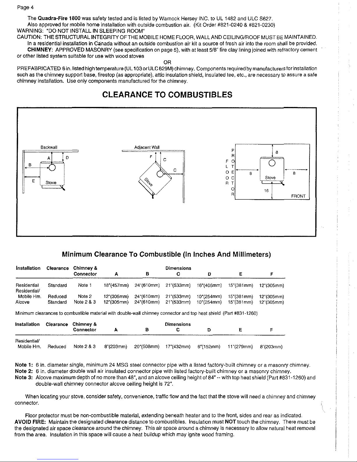
CLEARANCE TO COMBUSTIBLES
Minimum
Clearance
To
Combustible
(In
Inches
And
Millimeters)
P
R
F
0
L
T
0
E
0
C
R
T
0
!?
Installation Clearance Chimney
&
Dimensions
Connector
A
I3
C
D
E
F
------
.
8
Stove
FCinhiT
Residential Standard Note1 18'(457mm) 24"(610mm) 21"(533mm) i6"(406mm) lY(381mm) lY(305mm)
Residential/
Mobile Hm. Reduced Note
2
12"(305mm) 24"(610mm) Zl"(533mm) lO"(254mm) lY(381mm) lY(305mm)
Alcove Standard Note2&3 lY(305mm) 24"(610mm) 21"(533mm) lO"(254mm) 15(38imm) lY(305mm)
Minimum clearances to combustible material with double-wall chimney connector and top heat shield (Pan #831-1260)
Installation Clearance Chimney
&
Dimensions
Connector
A
B
C D
E
F
Residential/
Mobile Hm. Reduced Note 2
&
3 V(203mm) 20(508mm) 17"(432mm) V(152mm) 1 l"(279mm) 8"(203mm)
Note
1: 6 in. diameter single, minimum 24 MSG steel connector pipe with a listed factory-built chimney or a masonry chimney.
Note
2:
6
in. diameter double wall air insulated connector pipe with listed factow-built chimnev or a masontv chimnev.
Note
3:
Alcove maximum depth of no more than 48", and a" .icoveceiling heightof 84" --with tbp heat shieldi~art #8$-1260) and
double-wail chimney connector alcove ceiling height is 72".
When locating your stove, cons~der safety, convenlence, trafflc flow and the fact that the stove w~ll need a ch~mney and ch~mney
connector.
Floor protector must be non-combust~ble maler~al, extend ng beneatn heater an0 to tne front, sldes and rear as ndlcaleo
AVOID
FIRE:
Maintain tne aesignated clearance d~stance to combust~bles. ins~lat on mJst NOT to-ch tne cnlmney Tnere m~st be
the designated air space clearance around the chimney. This air space around a chimney is necessary to allow natural heat removal
from the area. Insulation in this space will cause a heat buildup which may ignite wood framing.
VENTING SYSTEM
The venting system consists of a chimney connector and a chimney. These get extremely hot when the stove is being used.
Temperatures inside the chimney may exceed 2000" in the event of a creosote fire. To protect against the possibility of a house fire,
'he chimney connector and chimney must be properly installed and maintained. A thimble Must be used when a connection is made
,?rough a combustible wall to a chimney. A chimney support package Must be used when a connection is made through the ceiling
to a prefabricated chimney. These accessories are absolutely necessary to provide safe clearances to combustible wall and ceiling
material
. .
.
- . -
. . - . .
This stove may be connected toa lined masonrychimney or a listed high temperature prefabricated residential type building heating
appliance chimney. Do not connect it to a chimney sewing another appliance. To do so will affect the safe operation of both appliances.
CHIMNEY CONNECTOR
The chimney connector must be 6 in. diameter pipe with a minimum thickness of 24 gauge. Do not use aluminum or galvanized
steel. They cannot properly withstand the extreme temperatures of a wood fire. Do not use chimney connector pipe as a chimney. You
must connect your stove to a chimney at least equal to those specified in this manual.
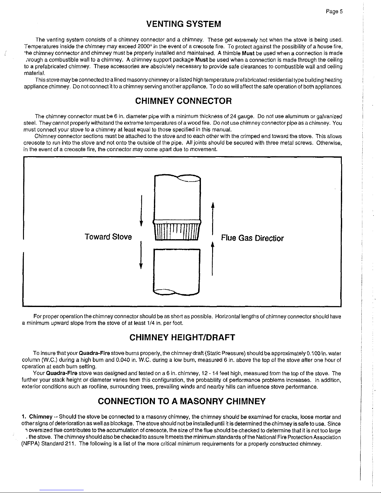
Chimnev connector sections must be attached to the stove and to each other with the crimoed end toward the stove. This allows
creosote to
iun into the stove and not onto the outside of the pipe. All joints should be secured with three metal screws. Otherwise,
in the event of a creosote fire, the connector may come apart due to movement.
Toward
Stove
Flue
Gas
Directior
For proper operation the chimney connector should be as short as possible. Horizontal lenqths of chimney connector should have
..
.
a minimum upward slope from the stove of at least 114 in. per foot.
-
CHIMNEY HEIGHTIDRAFT
To insure that your Quadra-Fire stove burns properly, the chimney draft (Static Pressure) should be approximately 0.100 in. water
column (W.C.) during a high burn and 0.040 in. W.C. during a low burn, measured
6
in. above the top of the stove afler one hour of
operation at each burn setting.
Your Quadra-Fire stove was designed and tested on a
6
in. chimney, 12 - 14 feet high, measured from the top of the stove. The
further your stack height or diameter varies from this configuration, the probability of performance problems increases. In addition,
exterior conditions such as roofline, surrounding trees, prevailing winds and nearby hills can influence stove performance.
Page
5
i
I
I
I
!
CONNECTION TO A MASONRY CHIMNEY
1.
Chimney
--
Should the stove be connected to a masonry chimney, the chimney should be examined for cracks, loose mortar and
othersignsof deterioration as well as blockage. Thestove should not be installed until it Is determined the chimney lssafe to use. Since
i
oversized flue contributes to the accumulation of creosote, the size of the flue should be checked to determine that it is not too large
,
the stove. The chimney should also be checked toassureit meets the minimumstandardsof the National Fire Protection Association
(NFPA) Standard 21
1.
The following is a list of the more critical minimum requirements for a properly constructed chimney.
Page
6
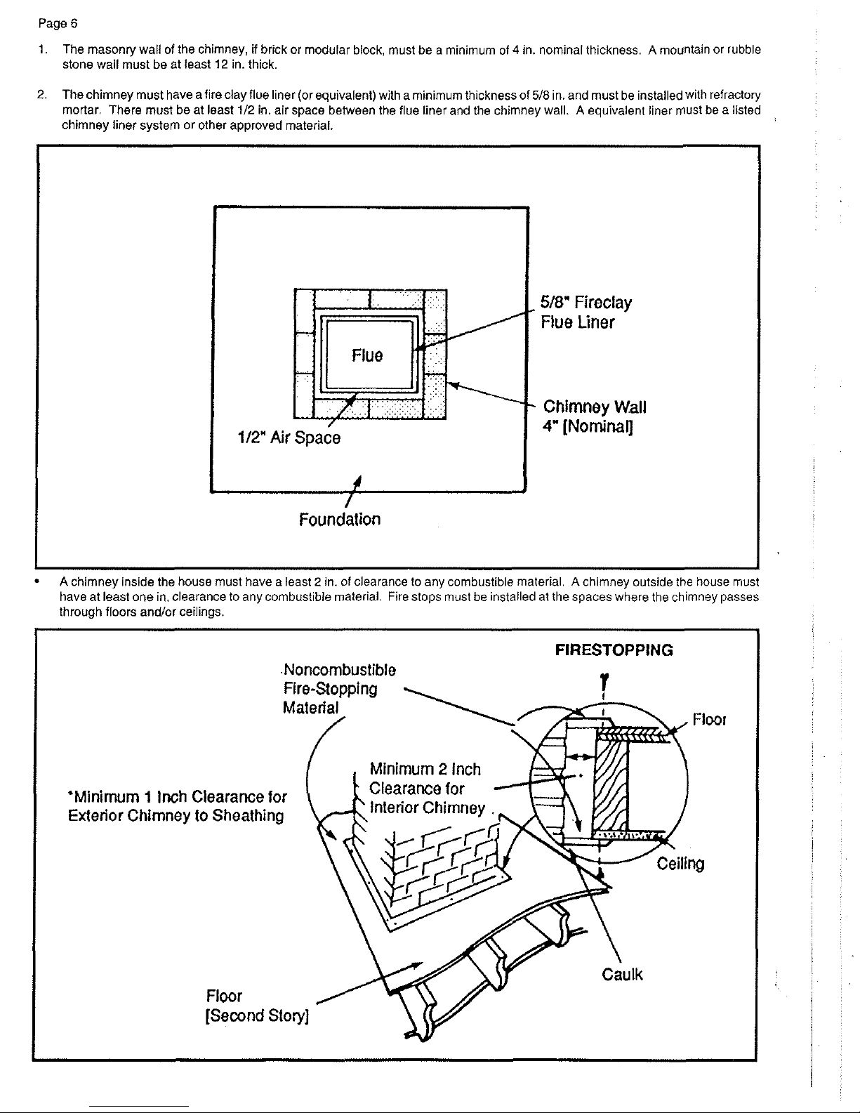
1.
The masonry wail of the chimney, if brick or modular block, must be a minimum of 4 in. nominal thickness. A mountain or rubble
stone wall must be at least
12
in. thick.
2.
The chimney must have afire clay flue liner (or equivalent) with a minimum thickness of
518
in. and must be installed with refractory
mortar. There must be at least
112
in. air space between the flue liner and the chimnev wail. A eauivalent liner must be a listed
chimney liner system or other approved meterial
518"
Fireclay
Flue Liner
Chimney Wall
4"
[Nominal]
/
Foundation
A
chimney inside the house must have a least 2 in. of clearance to any combustible material. A chimney outside the house must
have at least one in. clearance to anvcombustibie material. Fire stops must be installed at the spaces where the chimnev passes
Page
7
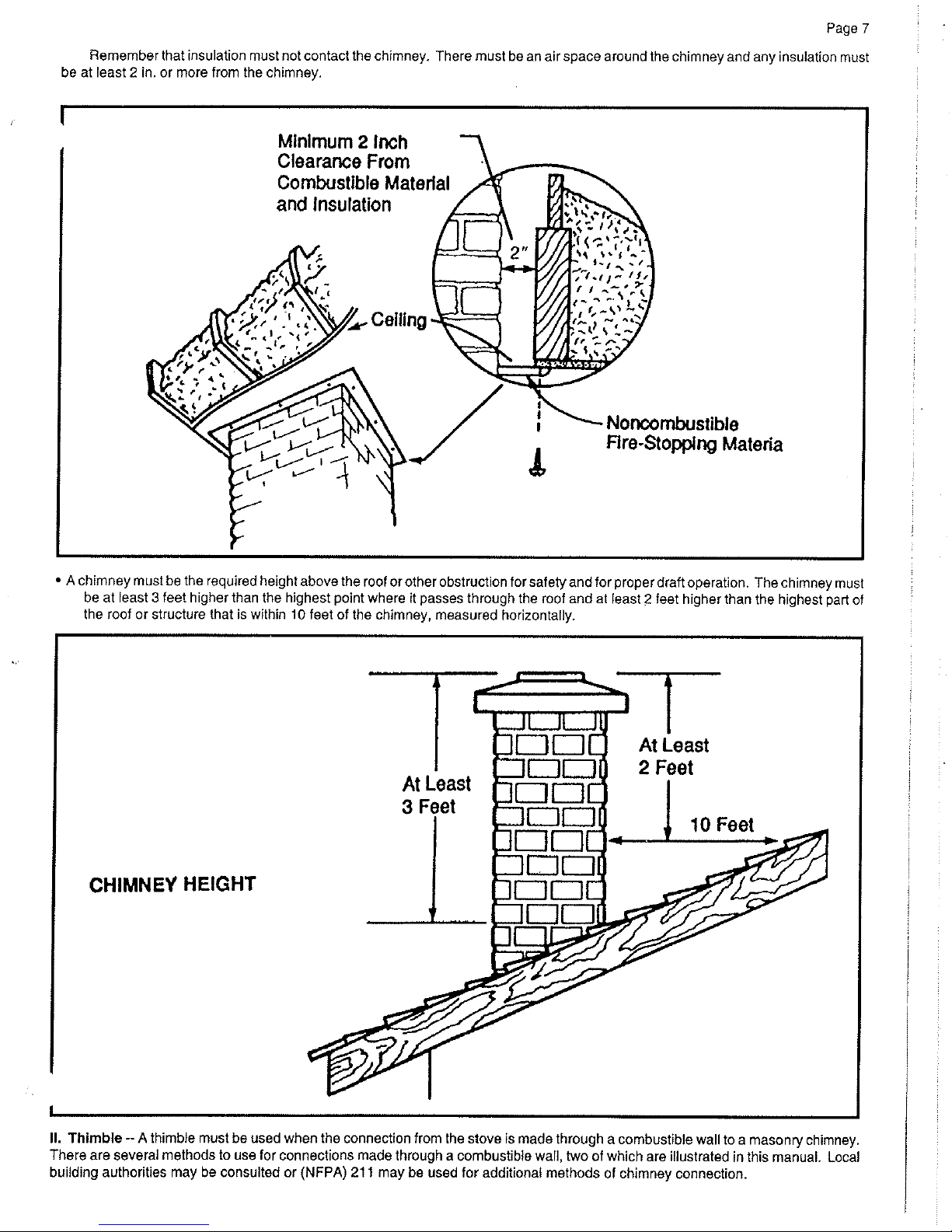
Remember that insulation must not contact the chimney. There must be an air space around the chimney and any insulation must
be at least
2
in. or more from the chimney.
Minimum 2 Inch
Clearance From
Combustible Material
and
Insulation
N~ncombustible
Rre-Stopping Materia
A
chimney must be the required heightabove the roof orother
obstructionforsafetyandforproper
draft operation. Thechimney must
be at least
3
feet higher than the highest point where it passes through the roof and at least 2 feet higher than the highest part of
the roof or structure that is within
10
feet of the chimney, measured horizontally.
CHIMNEY
HEIGHT
II.
Thimble
--
A
thimble must be used when the connection from the stove is made through a combustible wall to a masonry chimney.
There are several methods to use for connections made through a combustible wall, two of which are illustrated in this manual. Local
building authorities may be consulted or
(NFPA) 21
1
may be used for additional methods of chimney connection.

Page
8
Also, listed prefabricated metal thimbles can be bought for use with wood stoves. The manufacturer's installation instructions lor
a thimble must be strictly followed to assure the safety of the system. Be sure to maintain the designated clearance to combustible
materials.
1.
Brick chimney thimbleassembly
--
Construction of a brick thimble assembly requires 12 in. of brick around afire clay liner.
Be sure the point of penetration allows a
24
in. clearance from the top of the connector to the ceiling. An opening of
30
in. (for
a
6
in. chimney connector) must be cut in the wall to maintain the required 12 in. of brick separation from combustibles. It will
be necessary to cut wall studs and install a header and sill frame to maintain the proper dimensions and to hold the weight of
the brick.
Wood Stud 2 lnches Clearance
.From Chimney Wall
Header
1!11
16
Thimble
ASS^^^^\^.
1
2
Inches
of
Brick
Separation From Clay
Fireclay Liner
518"
~inimum
'
or Eauivalent
Wall
Minimum 3-112 in.
(4
in. nominal) thick solid bricks are to be used. The fire clay liner (ASTM C35 or equivalent) minimum 518 in
wall thickness, must not penetrate into the chimney beyond the inner surface of thechimney flue liner and must be firmly cemented in
place. if it is necessary to cut a hole in the chimney liner, useextreme care to keep it from shattering. Refractory mortar must be used
at the junction to the chimney liner. After the assembly is complete, insert the chimney connector in the fire clay liner. Do not push it
beyond the inside edge of the chimney liner because this will affect the draw of the chimney.
 Loading...