

Page 1

QSTC201/211
IP Camera
User’s Manual
Q-see Products
8015E.Crystal Dr
Anaheim, CA 92807
Website:
http://www.q-see.com
Phone: 877-998-3440 x 538
Rev082009
Page 2

QSTC201/211 IP-CAMERA USER MANUAL
Before using this product
Before operating, we strongly advise users to read this manual and keep it
handy for later use.
This manual provides product instructions but we do not warranty the contents.
We reserve the right to amend typographical errors, and the product may
change due to software upgrades and product improvements. Any changes will
be published in the latest version without special notification.
2
Page 3

QSTC201/211 IP-CAMERA USER MANUAL
Table of Contents
1 Introduction .................................................................................................................................................... 5
1.1 Product Summary .................................................................................................................. 5
1.2 Check package contents ........................................................................................................ 5
1.3 IP-CAMERA interface introduction ......................................................................................... 6
1.3.1 Front View of IP-CAMERA ........................................................................................... 6
1.3.2 Back View of IP-CAMERA ............................................................................................ 7
1.3.3 Top View of IP-CAMERA .............................................................................................. 8
2 Installation ..................................................................................................................................................... 8
2.1 Attach IP-CAMERA to Ethernet network ................................................................................. 8
2.2 IP-CAM hardware installation ................................................................................................. 9
2.3 Install CMS .......................................................................................................................... 10
2.3.1 Install process ............................................................................................................ 12
3 Internet Explorer Remote Access .......................................................................................................... 18
3.1 LAN ..................................................................................................................................... 18
3.2 WAN .................................................................................................................................... 20
4 Remote Preview ........................................................................................................................................... 22
4.1 The remote viewing interface is shown below: ...................................................................... 22
4.2 Configuration: Video Stream, Enable Audio .......................................................................... 23
4.3 Using 2 Way Audio .............................................................................................................. 25
5 Remote Live Surveillance ......................................................................................................................... 26
5.1 Main Menu Setup ................................................................................................................ 26
5.2 System Configuration .......................................................................................................... 26
5.2.1 Server basic configuration .......................................................................................... 26
5.2.2 Date & Time configuration .......................................................................................... 27
5.2.3 SD Card..................................................................................................................... 28
5.3 Channel configuration .......................................................................................................... 28
5.3.1 Basic configuration .................................................................................................... 28
5.3.2 Image configuration ................................................................................................... 29
5.3.3 Network image configuration ...................................................................................... 30
5.4 Alarm configuration .............................................................................................................. 31
5.4.1 Motion detection ........................................................................................................ 31
5.4.2 Motion alarm .............................................................................................................. 31
5.4.3 Motion Schedule ........................................................................................................ 32
5.4.4 Sensor alarm ............................................................................................................. 33
5.4.5 Sensor schedule ........................................................................................................ 34
5.4.6 Other alarm................................................................................................................ 35
5.4.7 Alarm out ................................................................................................................... 36
3
Page 4

QSTC201/211 IP-CAMERA USER MANUAL
5.5 Network configuration .......................................................................................................... 36
5.5.1 Basic configuration .................................................................................................... 36
5.5.2 IP configuration .......................................................................................................... 38
5.5.3 Wireless configuration ................................................................................................ 39
5.5.4 DDNS configuration ................................................................................................... 40
5.6 User configuration................................................................................................................ 42
5.7 Notification configuration ...................................................................................................... 44
5.8 Advanced configuration ........................................................................................................ 45
5.8.1 Upgrade..................................................................................................................... 45
5.8.2 Security configuration ................................................................................................ 45
5.8.3 Default configuration .................................................................................................. 46
5.8.4 Reboot device ............................................................................................................ 46
6 Video Search.................................................................................................................................................. 47
7 Mobile Surveillance ................................................................................................................................... 48
7.1 Accessing by Phones with Windows Mobile Pro ................................................................... 49
7.2 Accessing by Phones with Symbian ..................................................................................... 50
7.3 Accessing from iPhones ....................................................................................................... 54
8 Questions & Answers ................................................................................................................................. 62
9 Specifications ................................................................................................................................................ 66
10 Q-See Product Warranty .......................................................................................................................... 68
4
Page 5
QSTC201/211 IP-CAMERA USER MANUAL
指
南
1
Introduction
1.1 Product Summary
This IP-CAMERA is a video surveillance device designed especially for CCTV
systems. It uses H.264 compression technology with a high-powered decoding chip,
and uses advanced IT technology, such as video encoding and decoding
technology, complies with the TCP/IP protocol, SoC, etc… to ensure this system is
stable and reliable. This unit consists of two parts: the IP-CAMERA device and
central management software. The central management software (CMS) allows you
to view and control multiple devices via internet or LAN and establishes a sound
surveillance system with unified management and remote operation for all the
devices in one network.
This product is widely used in banks, telecommunication systems, electricity power
departments, law systems, factories, storehouses, cities and so on. It is an ideal
choice for surveillance sites with middle or high risks.
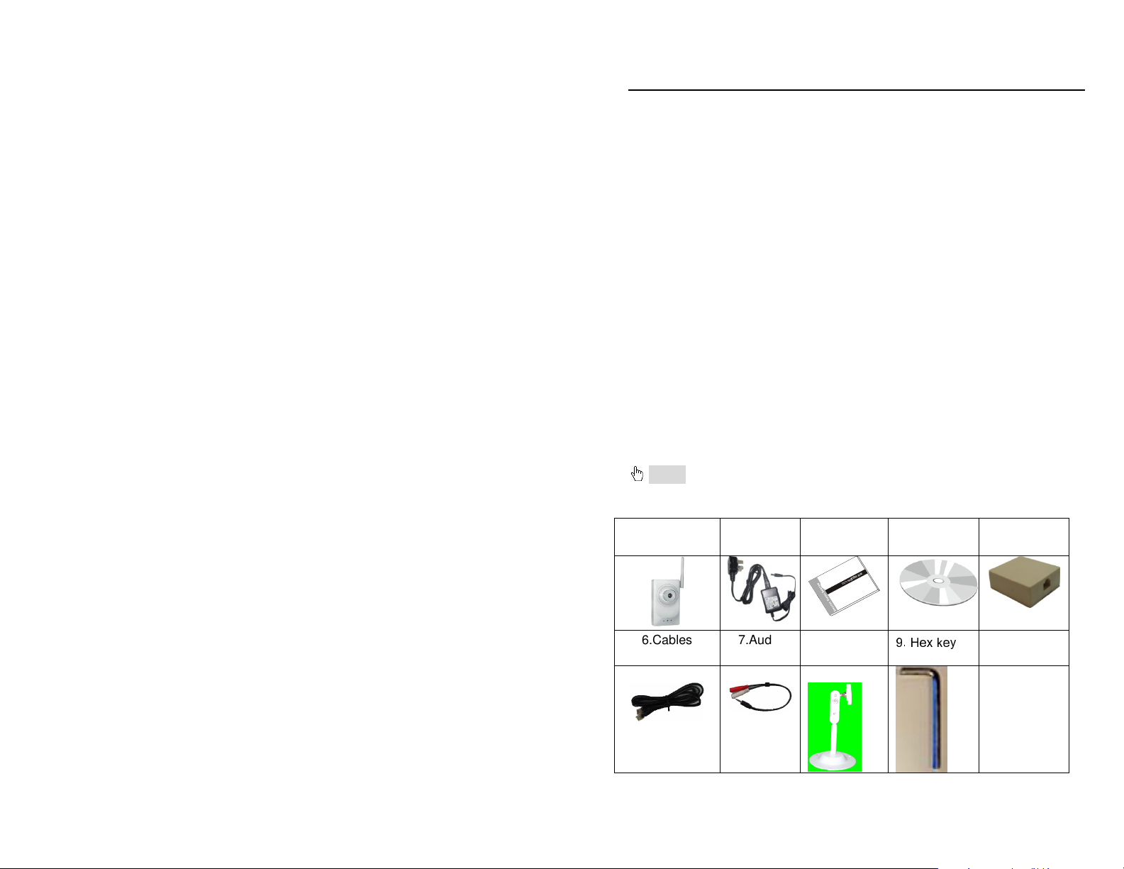
1.2 Check package contents
The package should contain all the following:
Notice: the pictures below are only for reference; the actual items may
look different
1.IP-CAMERA
module
2.Power
adapter
3.User’s
manual
4.CMS CD 5.Alarm box
用
使
速
快
S
V
D
6.Cables 7.Audio
line
8. Camera
Stand
9. Hex key
5
Page 6
QSTC201/211 IP-CAMERA USER MANUAL
Functions of accessories:
NO. Accessories Description
1 IP-CAMERA module The Camera
2 Power adapter The power adapter output DC 12V, which
supplies the power to the IP-CAMERA.
3 User manual The instructions for using the product
4 CD CD-ROM with software and manual
5. Alarm box Connect to alarm
6 Cable 1 Connect device to the alarm box
Cable 2 Connect the IP-CAMERA to the Internet
7 Audio line Connect to MIC & Headphones
8 Camera Stand Attach to back of IP Camera
9 Hex Key Adjust Screws on Camera Stand
1.3 IP-CAMERA interface introduction
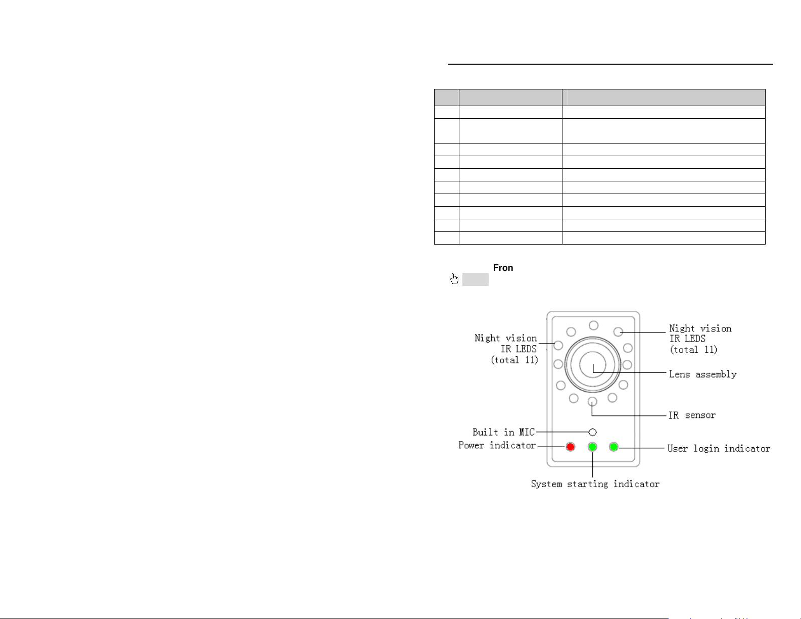
1.3.1
Front View of IP-CAMERA
Notice: the pictures below are only for reference; the actual items may
look different
6
Page 7
QSTC201/211 IP-CAMERA USER MANUAL
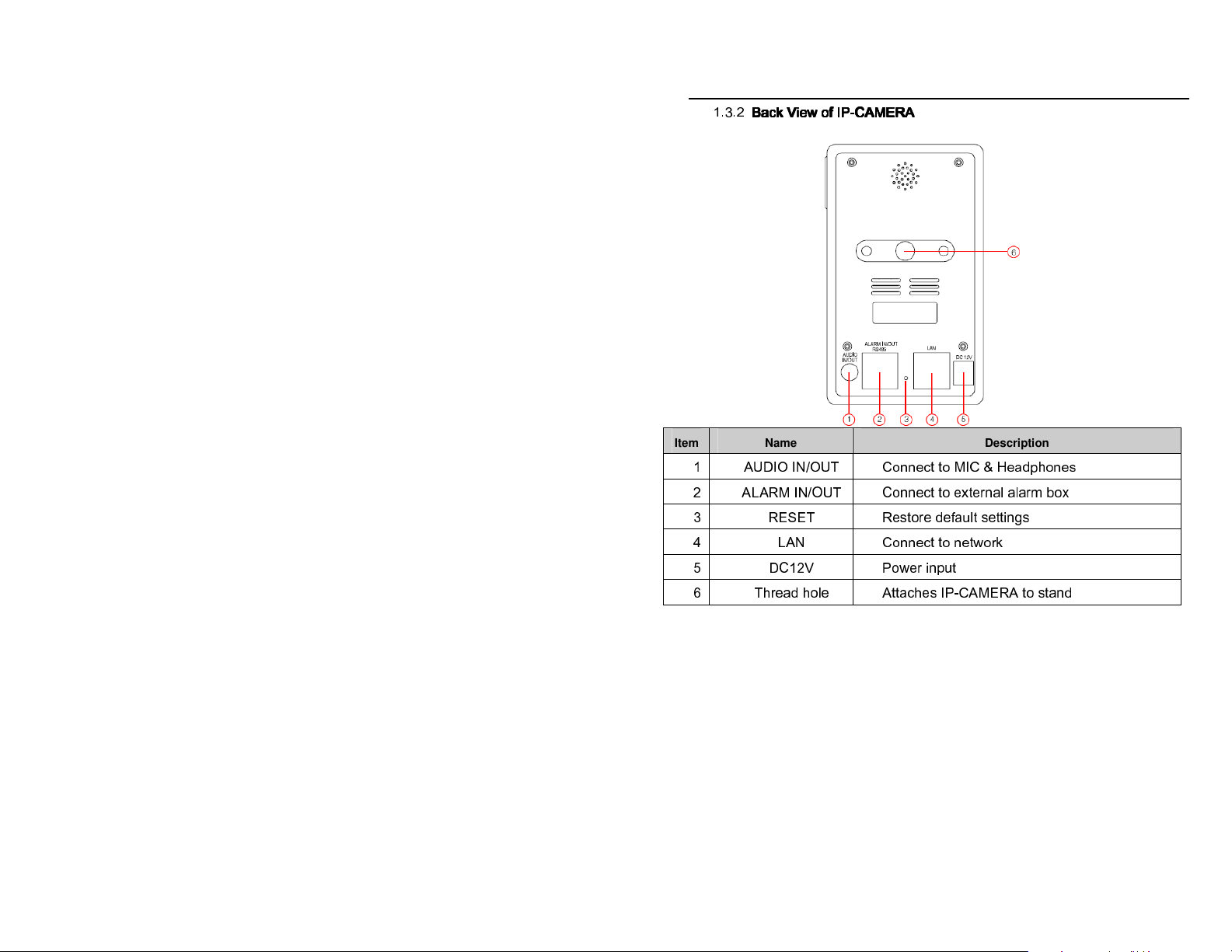
1.3.2
Back
Back VVVView
iew of
of IP
IP----CAM
CAMERA
Back Back
iew iew
ofof
IPIP
CAMCAM
ERA
ERAERA
Item
1 AUDIO IN/OUT Connect to MIC & Headphones
2 ALARM IN/OUT Connect to external alarm box
3 RESET Restore default settings
4 LAN Connect to network
5 DC12V Power input
6 Thread hole Attaches IP-CAMERA to stand
Name Description
7
Page 8
QSTC201/211 IP-CAMERA USER MANUAL
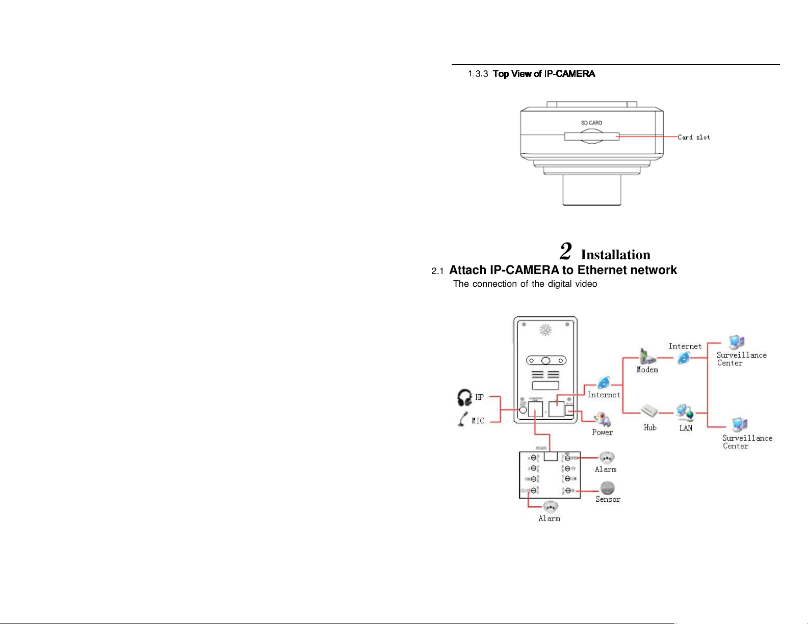
1.3.3
Top
Top VVVView
iew of
of IP
IP----CAM
CAMERA
TopTop
iewiew
ofof
IPIP
CAMCAM
ERA
ERAERA
2
Installation
2.1 Attach IP-CAMERA to Ethernet network
The connection of the digital video server is show below. Video input devices,
audio input devices and alarms should be connected first, then the power supply
is connected.
Fig 2-1 Connections
8
Page 9
QSTC201/211 IP-CAMERA USER MANUAL
User can connect the PC (Surveillance Center) and IP-CAMERA as shown in the
above picture. Before connecting to PC, user needs to connect external devices,
and then connect the power. Connecting sensors or alarm boxes is optional and
depends on user’s needs.
The connection steps are shown below:
Step 1: Transfer line 1 connects to alarm box and IP-CAMERA first, and then
connect to alarm devices. (For more details please refer to IP-CAMERA
hardware installation 2.2).
Step 2: Transfer line 2 connects to MIC and Headphones
Step 3: Internet line connects to Internet broadband modem or router.
Step 4: Connect power cable to a power outlet
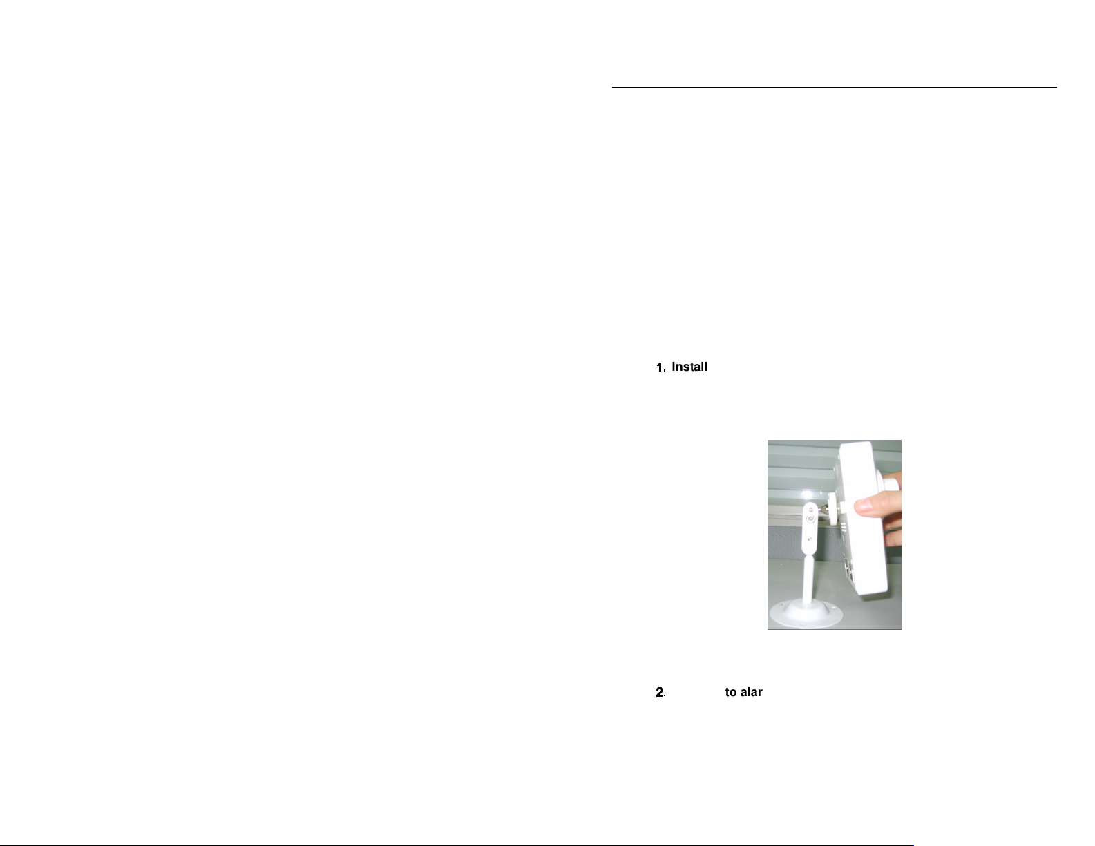
2.2 IP-CAM hardware installation
This section describes how to connect camera stand and alarm devices
(optional).
1.
1.
Install IP-CAMERA
1.1.
Step 1: Turn one end of the extension stand to the screw hole on the groove of
the base
Step 2: Turn the other end of the extension stand clockwise on the screw hole of
the IP-CAMERA and adjust it as shown in Fig 2-2
Fig 2-2 Install IP-CAM
Step 3: Adjust the IP-CAMERA and the stand to the desired position
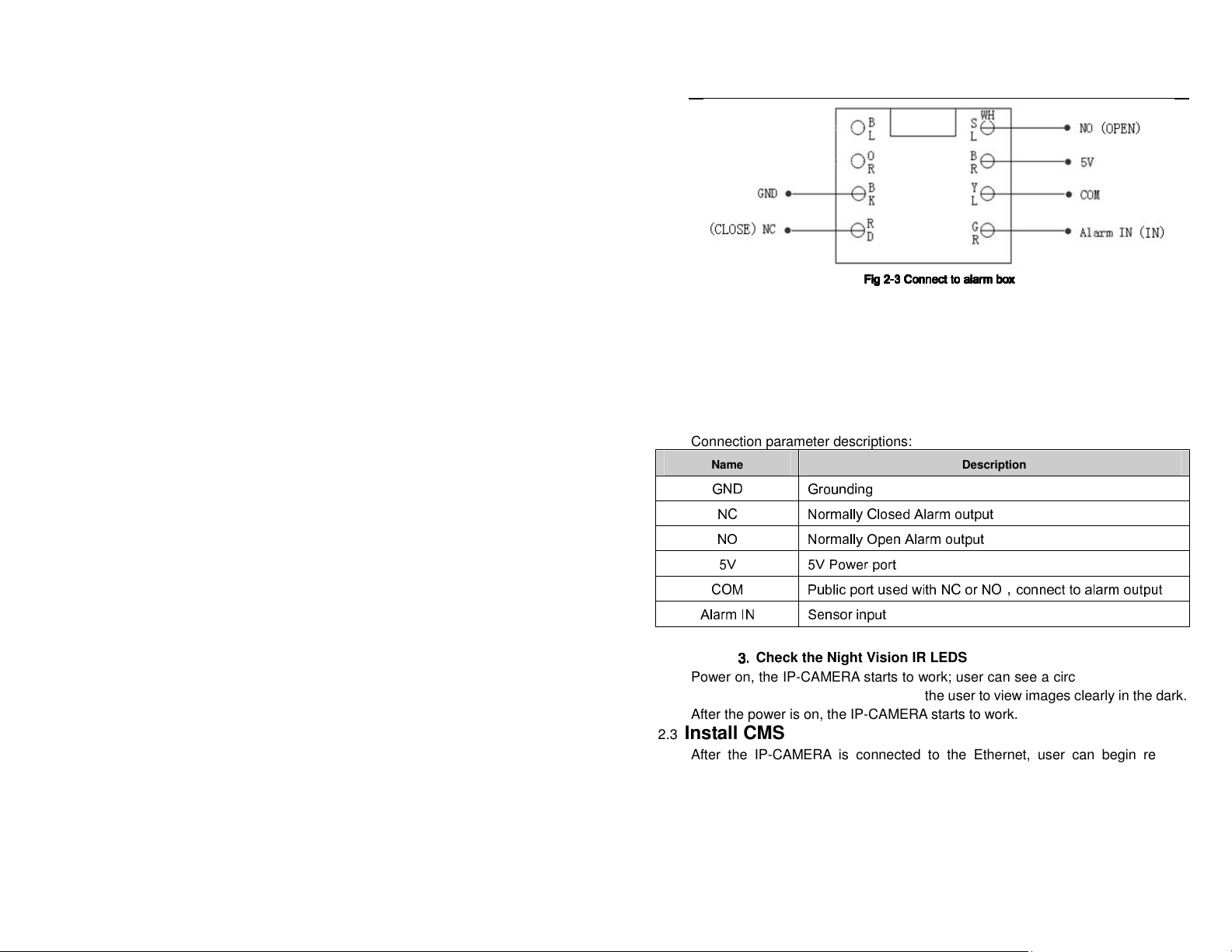
2.
2.
Connect to alarm devices as shown as Fig 2-3
2.2.
9
Page 10
QSTC201/211 IP-CAMERA USER MANUAL
Fig 2
Fig 2----3333 Connect to alarm box
Connect to alarm box
Fig 2Fig 2
Connect to alarm boxConnect to alarm box
Connection parameter descriptions:
Name Description
GND Grounding
NC Normally Closed Alarm output
NO Normally Open Alarm output
5V 5V Power port
COM Public port used with NC or NO,connect to alarm output
Alarm IN Sensor input
3.
3.
Check the Night Vision IR LEDS
3.3.
Power on, the IP-CAMERA starts to work; user can see a circle of lights around
the LENS of IP-CAMERA which allow the user to view images clearly in the dark.
After the power is on, the IP-CAMERA starts to work.
2.3 Install CMS
After the IP-CAMERA is connected to the Ethernet, user can begin remote
monitoring and managing the device by using the client software or IE browser.
This chapter explains how to use the client software, and is the quick install
guide for the CMS. For operation and monitor setting details please refer to the
CMS user manual on the included CD.
Note: Before installing control center software in your computer, please
10
Page 11

QSTC201/211 IP-CAMERA USER MANUAL
make sure all anti-virus software in the computer is disabled so that CMS
can install correctly.
System requirements
•
Supported Operating Systems:
Operating
system
Windows XP Windows XP SP2 or most recent patch,
Windows Vista Windows Vista
Comments
DirectX 9.0c or above
DirectX 10.c
Computer hardware requirements
Please make sure the system is running well and the computer is
compatible:
•
Recommended PC Specifications – 4 channels
Item Specification
CPU Intel Pentium 3.0 GHz or AMD 3000+
Memory 1GB
HDD 160GB
•
Recommended PC Specifications -9 channels:
Item Specification
CPU Intel Core 2 Duo 1.8 GHz or AMD Dual core 3800+
Memory 1GB
HDD 250GB
•
Recommended PC Specifications -16 channels:
Item Specification
CPU Intel Core 2 Duo 2.2 GHz or AMD Dual core 3800+
Memory 2GB
11
Page 12
QSTC201/211 IP-CAMERA USER MANUAL
HDD 250GB
Notice:
The above recommended specifications are for CIF resolution.
The AMD hyper-3800+ and X64 series chips have not been tested;
If user wants to have real-time live view with CIF resolution
(352x240), the max connection number is 16 on one computer;
If user wants to have real-time live view with D1 resolution
(704x480), the max connection number is 4 on one computer.
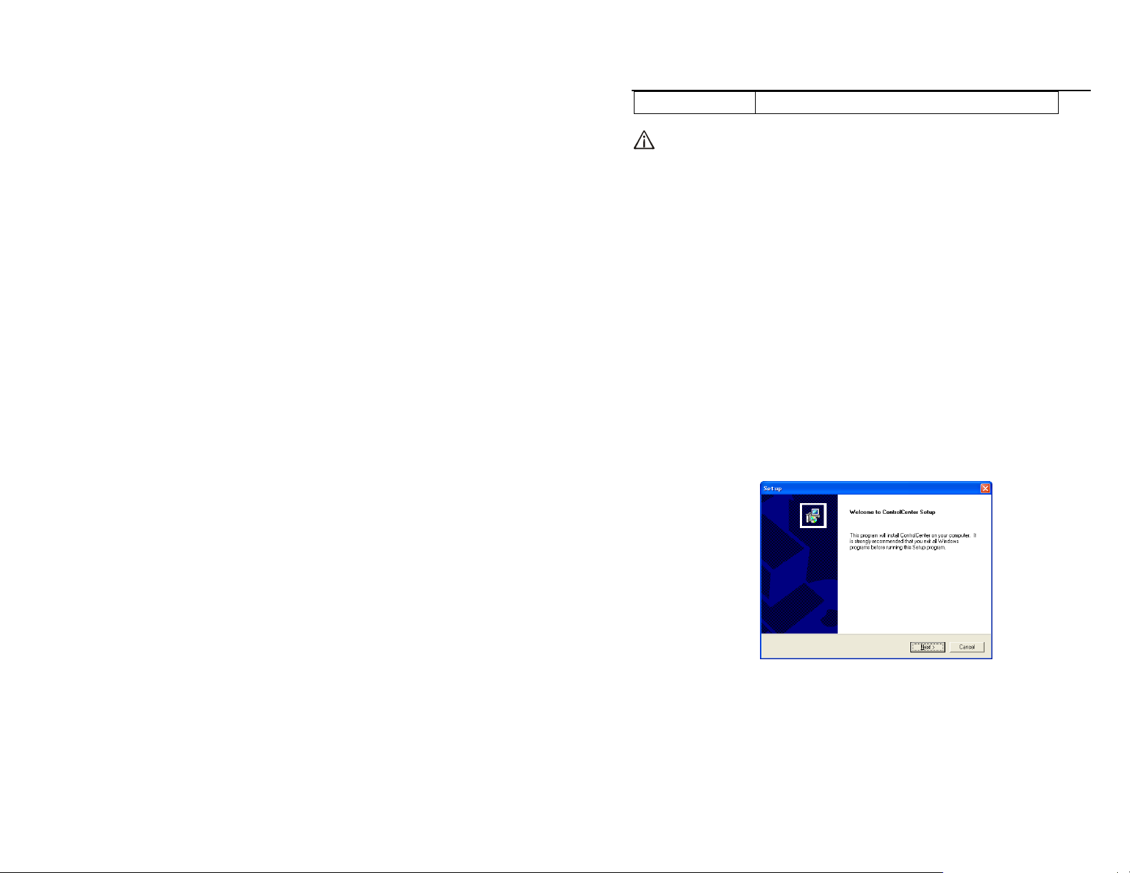
2.3.1 Install process
1. Run the “Control Center” from software CD, double click “Setup.exe” file,
Figure2-4 window will pop up:
Figure2-4 Welcome menu
2. Click “Next” to enter the next step, shown as Figure2-5:
12
Page 13
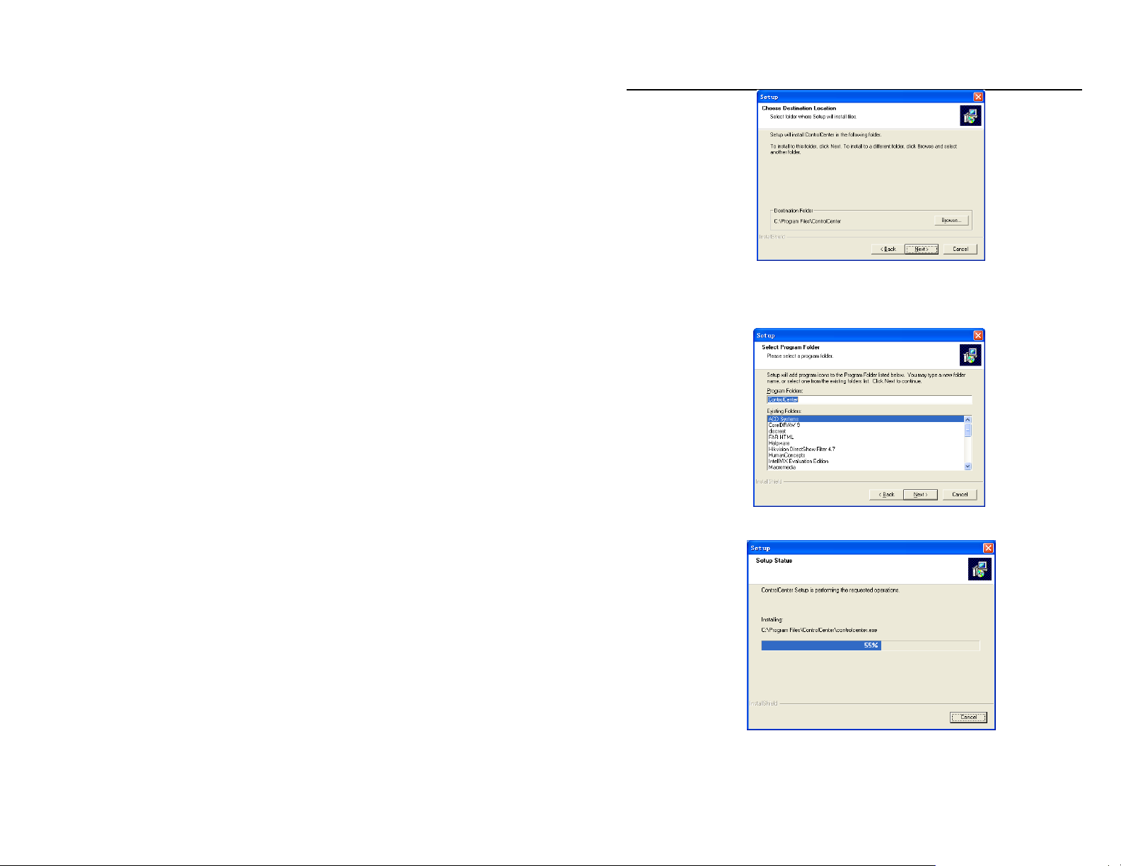
QSTC201/211 IP-CAMERA USER MANUAL
Figure2-5 Choose the installation destination
3. The default installation destination folder is “C:\Program Files”, user can
click “Browse” button to change it. After selecting the destination, click “Next” to
enter the next step shown as Fig 2-6:
Figure2-6 selects a folder to install in
4. Click “Next” to start installing and display Fig 2-7:
Figure2-7 the rate of installation progress
5. The installation is complete shown as Fig 2-8:
13
Page 14
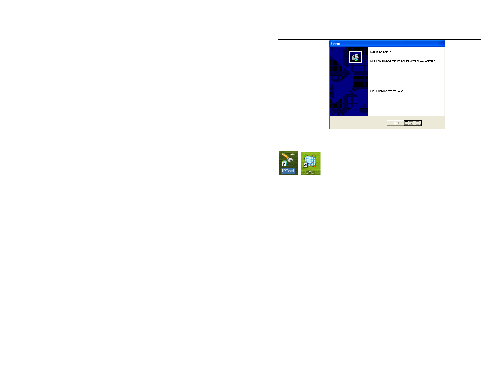
QSTC201/211 IP-CAMERA USER MANUAL
Figure2-8 Setup Complete
6. Click “Finish” to complete setup, and see the “Control Center” icon
on the desktop.
7. Double click CMS icon to start the software, the default user name is
“system”, and password is “123456”, user can change it as shown in the
corresponding chapter, for detailed introductions refer to “user manager” in user
manual. The CMS preview interface is shown as Fig 2-9:
14
Page 15
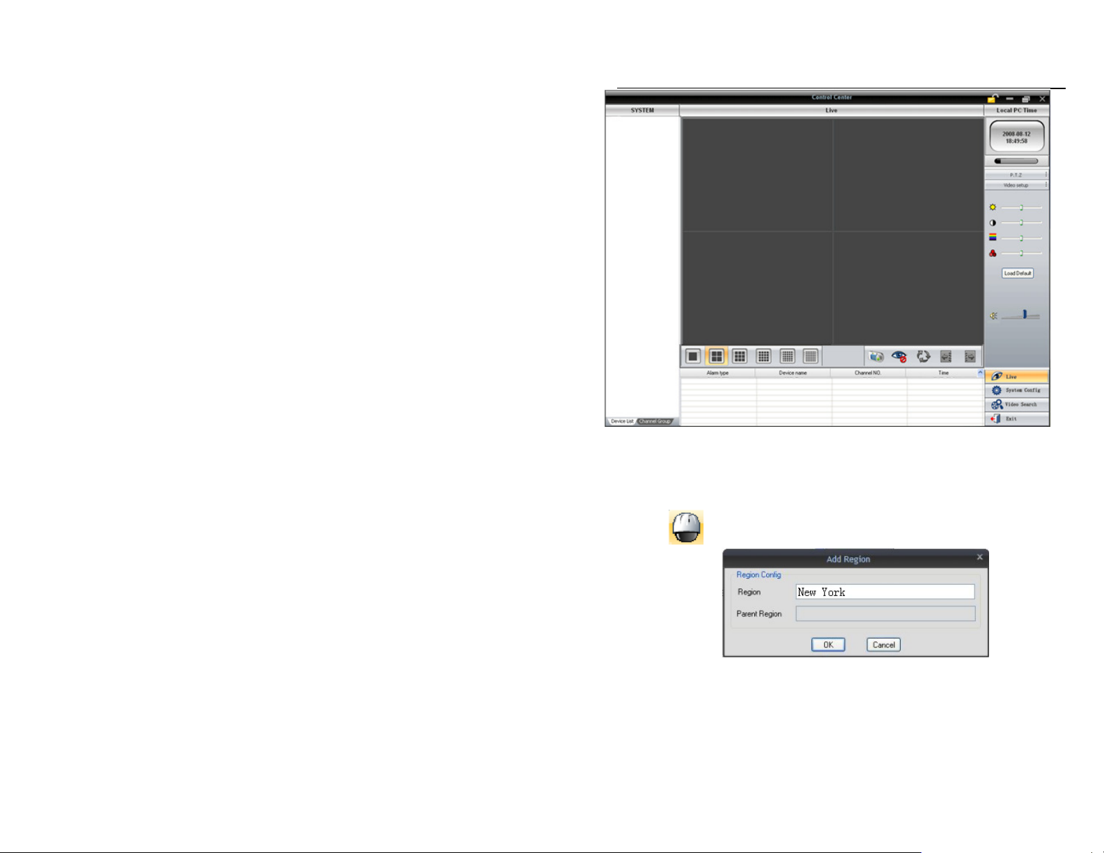
QSTC201/211 IP-CAMERA USER MANUAL
Figure2-9 Preview interface
8. Add device:
User can add video monitor device or sub region under the heading of add
region.
Step 1: Enter into the System Configuration menu, click 'Device
Manager , input the region name in 'Region' textbox. Refer to Fig 2-10:
Fig 2-10 Add region
15
Page 16
QSTC201/211 IP-CAMERA USER MANUAL
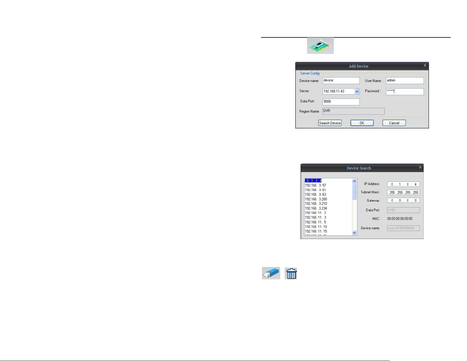
Step 2: Click
button; 'Add Device' dialog box will pop up refer to
Fig 2-11:
Fig 2-11 Add device
Step 3: If the monitor device exists with the PC at the same LAN, click the
“Search device” button, CMS will search for the compatible device in LAN and
list the details in the “Device search” dialog box. Double click an item, it will be
added to the information list on the right refer to Fig 2-12:
Fig 2-12 Device search
Note: CMS and IP Tool can’t run at the same time or the device
information won’t search and display.
Step 4: In the “Channel Group” dialog box select a device or area, click
or icon, user can rename or delete the selected device or area.
Select channel, user can rename the displayed name in this channel.
After successfully adding a device, user can re-group the channel of all
devices. Following these steps:
Step 1: change the interface to “Channel Group”
Notice: Please close the live preview when previewing channel or
recording in the device list.
16
Page 17
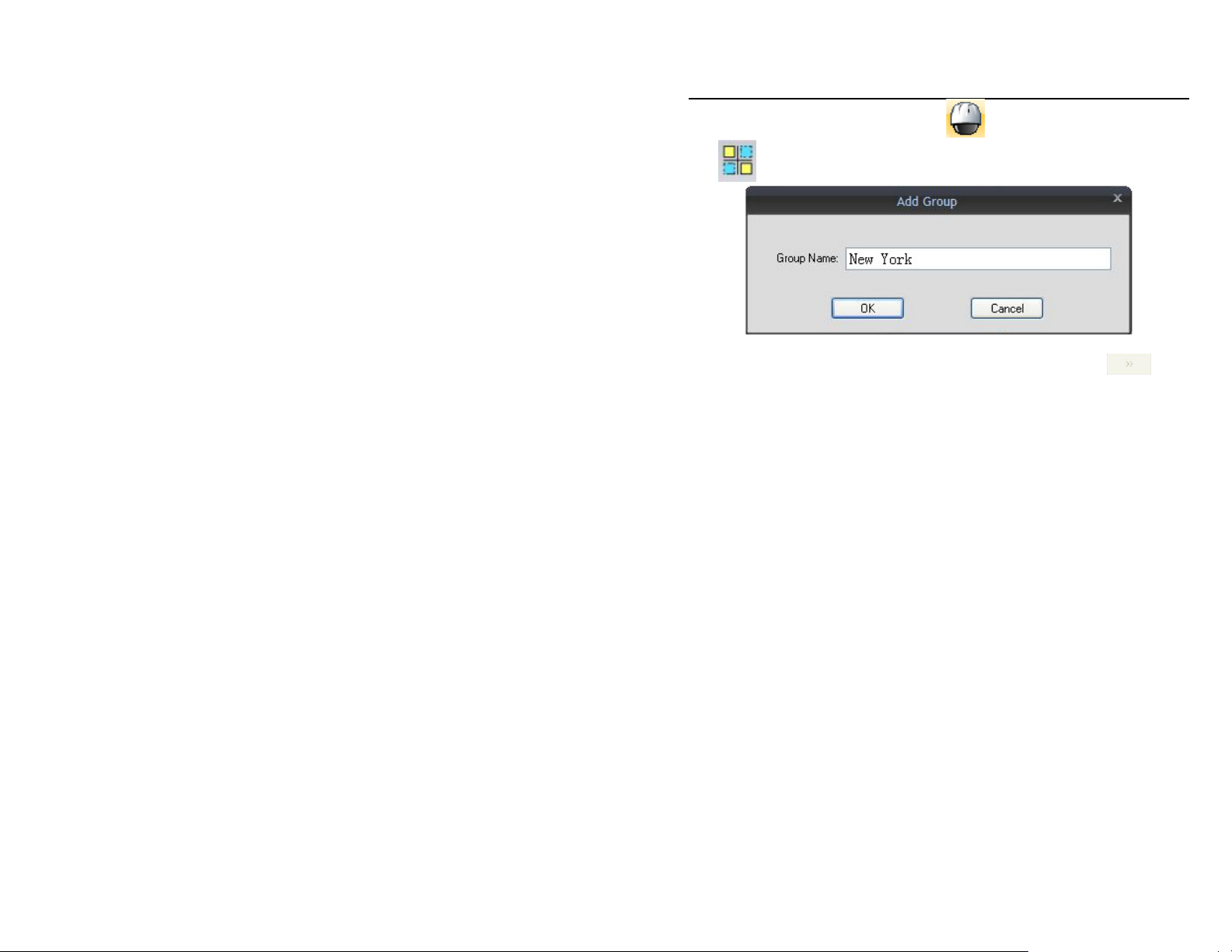
QSTC201/211 IP-CAMERA USER MANUAL
Step 2: Clicking ‘Device Manager
click
icon, add group name. Refer to Fig 2-13
Fig 2-13 Add group
Step 3: Select the channel in the “Device list” edit box, click icon,
and add the channel into “Channel group” edit box.
enters into “Device manager”,
17
Page 18
QSTC201/211 IP-CAMERA USER MANUAL
3
Internet Explorer Remote Access
The network service default settings are shown below:
IP address: 192.168.0.201
Subnet Mask: 255.255.255.0
Gateway: 192.168.0.1
HTTP: 80
Data port: 9008
When using the IP-CAMERA for the first time, please connect the device using
the above default settings, and reconfigure the setting according to your network.
Here we are using IE browser (above 6.0 versions) as an example; for operation
using CMS please refer to CMS user’s manual.
3.1 LAN
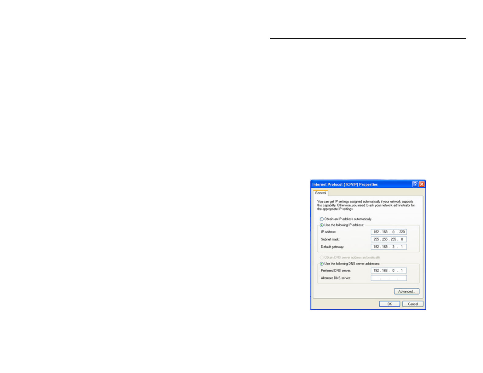
Step 1: Manually setup the IP address of the PC, the network segment should
be as same as the default settings of IP-CAMERA. Right click “My Network
Places” icon on the desktop, select “properties”; right click “Local Area
Connection” on the pop-up window, and then select “properties”. Select “Internet
Protocol (TCP/IP)” in the “General” tab, click “properties”, manually input
network address information of the PC in the pop up window, refers to figure 3-1:
Fig 3-1 PC network setting
18
Page 19
QSTC201/211 IP-CAMERA USER MANUAL
Step 2: Open the IE Browser, input the default address of IP-CAMERA and
confirm, the IE browser will download an Active X control automatically. If IE
browser can’t download the Active X control, please refer to Q4 of Chapter 9
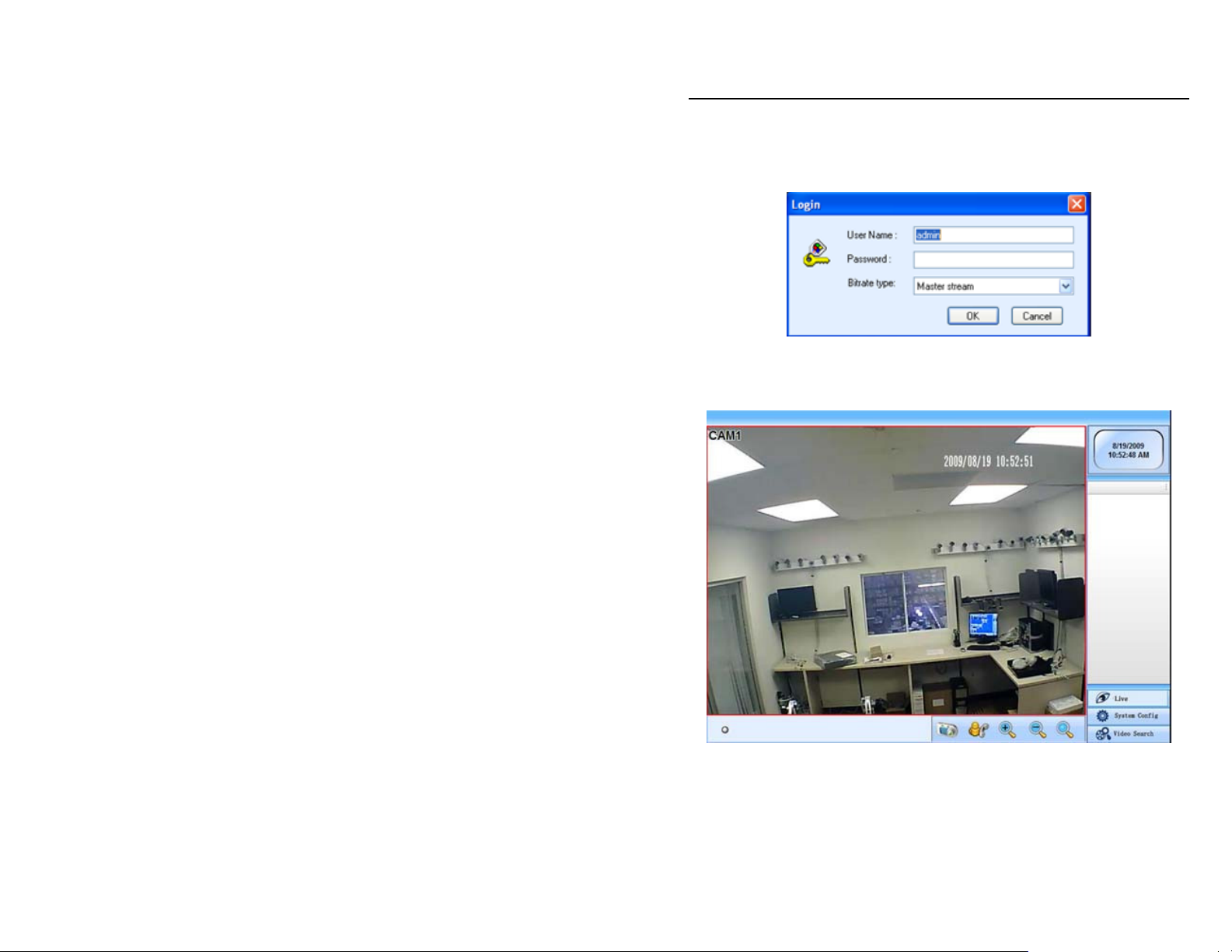
Step 3: After downloading the Active X control, the login dialog box will pop up
as shown in figure 3-2:
Fig 3-2 Login dialog box
Step 4: Input user name and password in the login dialog box, click “OK” button
to enter into the live view interface refer to Figure 3-3. User can manage and
setup the IP-CAMERA, such as changing IP address etc.
Fig 3-3 IE browser preview interface
Note: The default user name is “admin” and password is 123456
19
Page 20
QSTC201/211 IP-CAMERA USER MANUAL
3.2 WAN
Setting up the router:
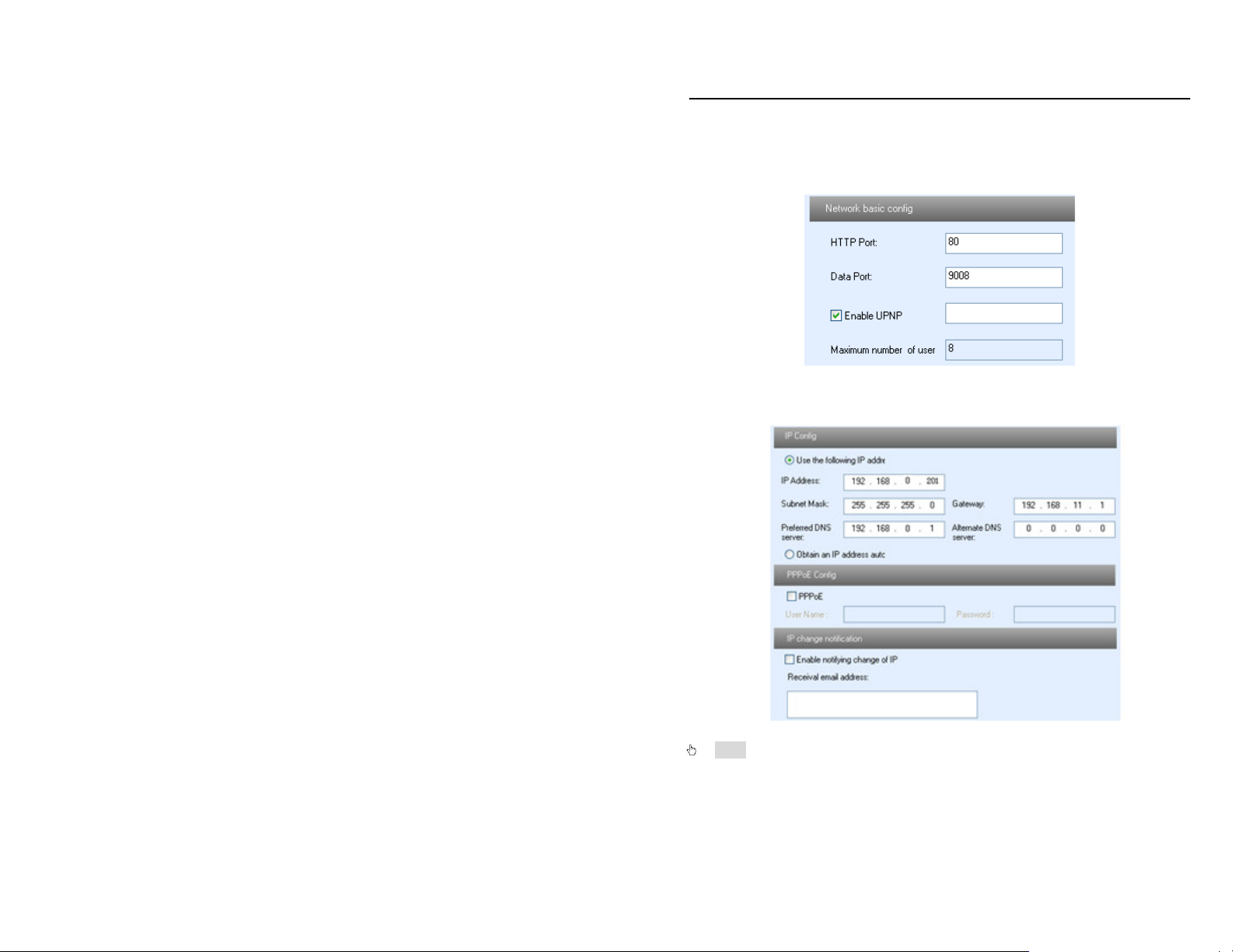
Step1: Connect according to above steps in LAN, enter into System
Configuration—Network configuration—Basic configuration, setup the port
numbers refer to Fig 3-4:
Fig 3-4 Port setup
Step 2: Enter into System Configuration—Network configuration—IP
configuration, change IP address refer to Fig 3-5:
Fig 3-5 IP setup
Note: The steps above should be saved after changing the port and IP
address. Log back into the device with the saved setting.
20
Page 21
QSTC201/211 IP-CAMERA USER MANUAL
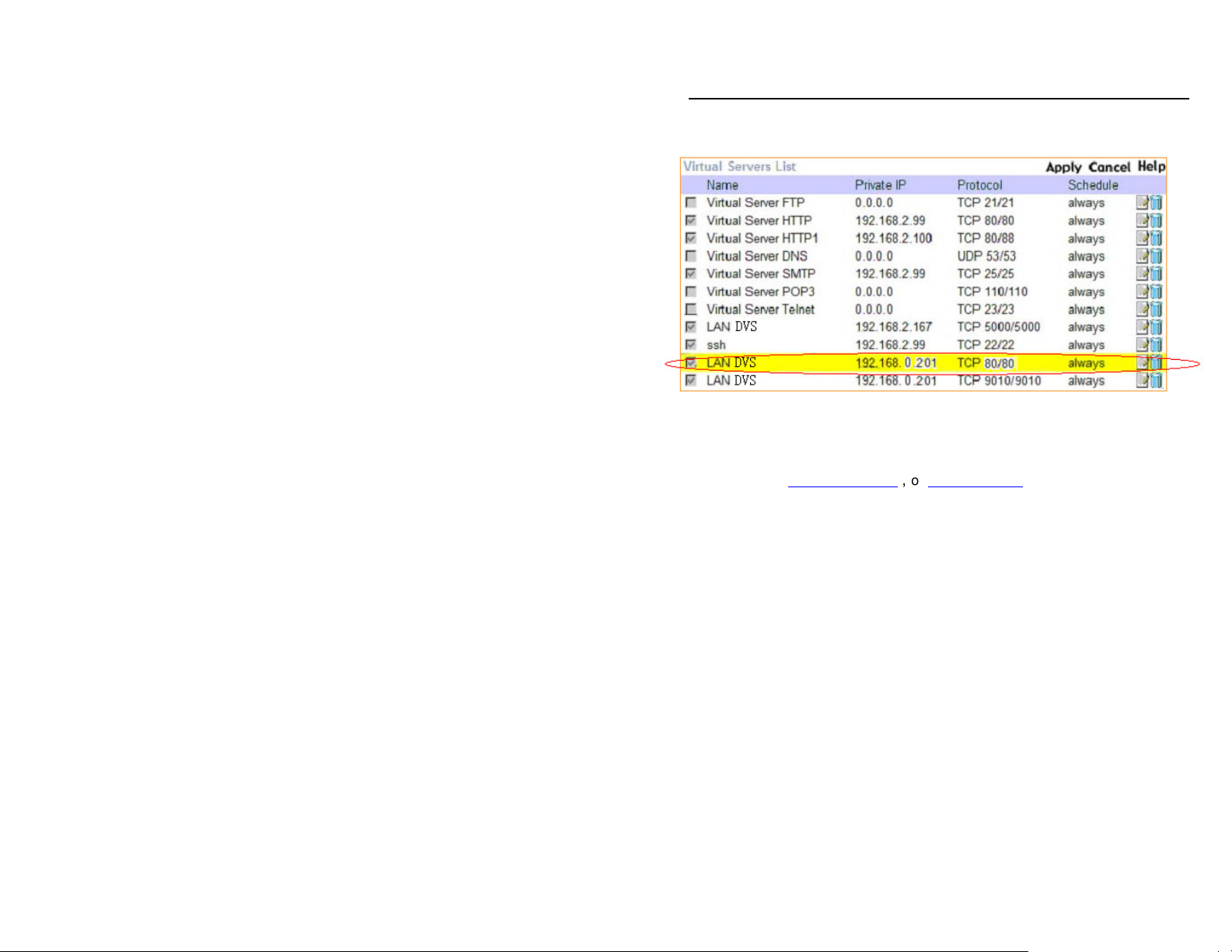
Step3: Enter into the router’s management interface through IE browser; forward
the port of IP-CAMERA to the IP address of the camera in the “virtual server”. Or
whatever the category is called on the router you are using. Refer to Fig 3-6
Fig 3-6 IP port forwarding
Step4: If the router is using a dynamic IP address, and you want to use a dynamic
domain name so you do not need to be concerned with the IP address constantly
changing on you, please apply for a domain name at a dynamic domain name service
website, such as www.dyndns.com,or www.no-ip.com. If you want to add the
domainname into the router, please check whether it supports the service or not.
Step 5: Open the IE browser, the setting steps are as same as “Step 2,3 and 4” in
LAN
21
Page 22

QSTC201/211 IP-CAMERA USER MANUAL
4
Remote Preview
4.1 The remote viewing interface is shown below:
Fig 4-1 remote preview interface
Symbol and function Definitions:
①
Motion Indicator
③
Click this button to enable two-way
talk.
⑤
Return to normal view
⑦
Search for video files
Note: Before doing audio talk; users should make sure microphone and
earphone connected with IP-CAMERA and PC work normally. Then
click right mouse button on the device to select talk. If connection is
successful, the device will turn to green. After connecting the MIC
device to MIC port, and then clicking icon, users can enable talk.
②
Picture snapshot
④
Zoom in and out
⑥
System Setup
22
Page 23

QSTC201/211 IP-CAMERA USER MANUAL
4.2 Configuration: Video Stream, Enable Audio
Click right mouse, a pull-down list will appear as shown below:
Fig 4-2 Right key sub-menu
Master Stream/Second Stream: select the video stream. This IP-CAMERA
supports master stream and sub stream. Master stream has higher frame rate,
max 30fps for every channel, but it needs higher network bandwidth to run
effectively; Second stream has low frame rate, max 3fps for every channel, it
requires lower network bandwidth. Therefore, users can select the stream
according to their available bandwidth.
Enable audio: enable remote audio transmission. Users can hear the audio
from the IP-CAMERA.
Full screen: the picture will fill the screen, without tool bar display. Double click
or click right mouse button to return to the previous interface.
Show status: show the connection status which user connects to device.
23
Page 24

QSTC201/211 IP-CAMERA USER MANUAL
Snap pictures:
1. Select a channel, click “Snap” icon, this will display Fig 4-3:
Fig 4-3 Single snap
2. User can take multiple pictures, select “frames”, such as 3, tick off “Title”
and “Time”, capture title and time will display simultaneously. Refer to Fig 4-4:
Fig 4-4 Multiple snap
3. Click “Browse” to set location to save file. Click “Save” to save pictures to
HDD on the computer and the save folder windows will open.
4. Click Exit to return to live viewing interface.
24
Page 25

QSTC201/211 IP-CAMERA USER MANUAL
4.3 Using 2 Way Audio
Here are instructions on how to use the 2 way communication feature
on the camera:
25
Page 26
QSTC201/211 IP-CAMERA USER MANUAL
5
Remote Live Surveillance
5.1 Main Menu Setup
User can remotely setup the parameters of the device. Functions of remote
configurations include: system configuration, channel configuration, alarm
configuration, network configuration, notification configuration and advance
configuration. User should first select the server on the menu list on the left, and
then setup the relative parameters. When a user sets up parameters of a certain
device, other users can not setup this device.
5.2 System Configuration
The “channel configuration” includes three submenus: server basic configuration,
date & time and SD Card.
5.2.1 Server basic configuration
In the “Server basic configuration” interface, user can setup the device name,
device ID and video format and can also check the relative information of the
server
Setting steps:
1. Click the "Server configuration" icon, the System configuration interface will
appear in the operation area.
2. Click the “Server basic configuration ", see Figure 5-1:
3."Mac Address" shows the MAC address of the device.
4. Input the name of the device in the "Device name" text box.
5. Input the device ID in the "Device ID" text box.
6. Select the video format between server and camera (in the USA we use
NTSC).
Note: After format changes the device will restart.
7. Press the "Save" button to save the settings.
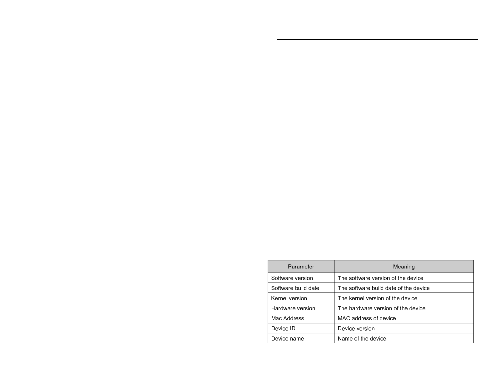
Please refer to the following table for parameters and instructions of server basic
configuration.
Parameter Meaning
Software version The software version of the device
Software build date The software build date of the device
Kernel version The kernel version of the device
Hardware version The hardware version of the device
Mac Address MAC address of device
Device ID Device version
Device name Name of the device.
26
Page 27

QSTC201/211 IP-CAMERA USER MANUAL
Parameter Meaning
Date format Display time in live view. Three formats: YY-MM-DD,
DD-MM-YY, MM-DD-YY
Fig 5-1 system configuration—server basic configuration interface
5.2.2 Date & Time configuration
Setting steps:
1. Enter into "system configuration" –“Date & Time” refer to Figure 5-2:
2. Choose the right "Time Zone" according to user’s location.
3. Select “Modify Time ", user can setup time by select the “Synchronize with
NTP Server” or “Set manually”. Select “Set manually”, user can self-define time;
tick off “PC time” check box, the manual setup time will be the same as the PC
time.
4. Press the "Save" button to save the settings.
Fig 5-2 system configuration—date & time interface
27
Page 28
QSTC201/211 IP-CAMERA USER MANUAL
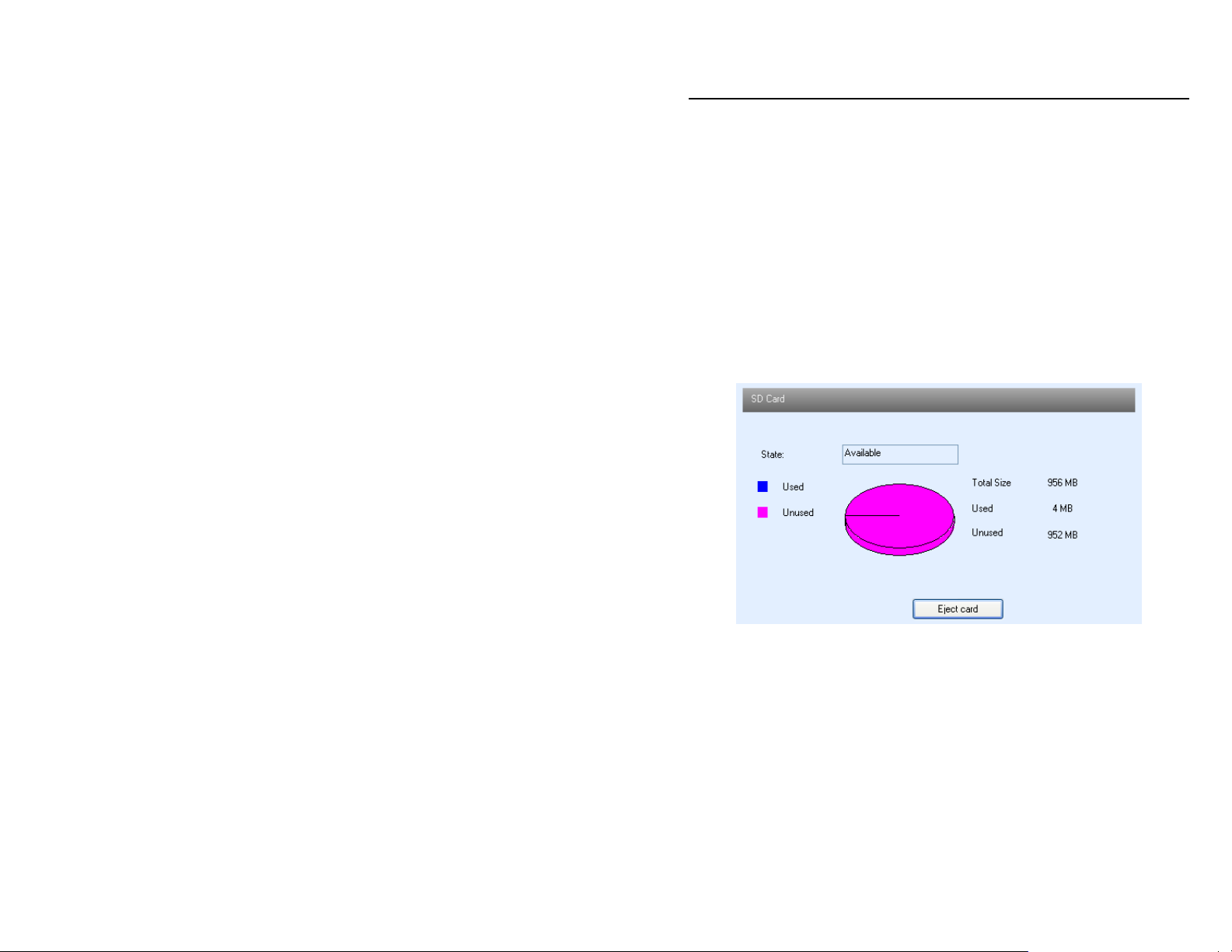
5.2.3 SD Card
Setup steps:
1. Enter into "system configuration" –“Date & Time” refer to Figure 5-3:
2. Usage status: Blue pane means used; red pane means unused.
3. Pressing "Eject card" terminates writing data to SD card, then it can be
ejected safely.
Note: Use of the SD card function should be coordinated with Motion alarm
and Sensor alarm, when alarm is triggered (refer to 5.3 Alarm configuration
for details), pictures can be stored on the SD card.
Fig 5-3 system configuration—SD card interface
5.3 Channel configuration
Channel Configuration includes four submenus: basic configuration, image
configuration, and network image configuration
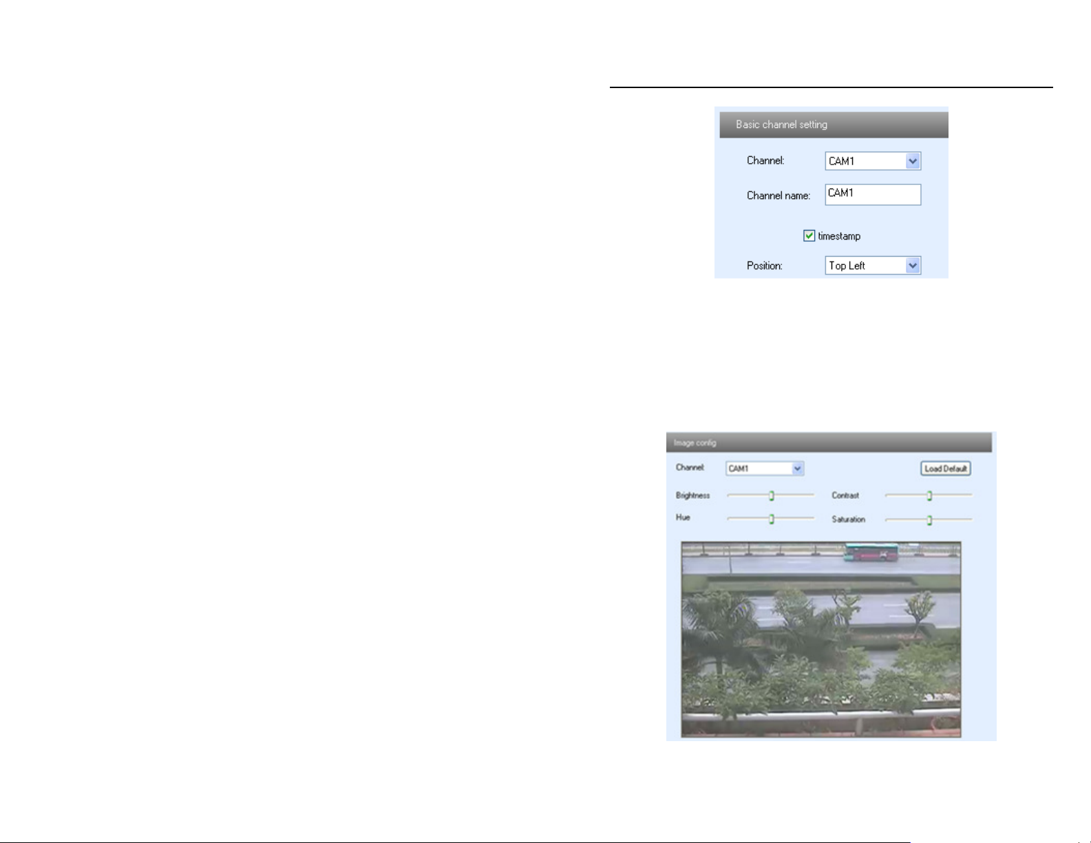
5.3.1 Basic configuration
Setting steps:
1. Enter into "Channel configuration"-- "Basic configuration" refer to Figure 5-4:
1. Select the channel to be setup on the "Channel Number" pull down list.
2. Input the channel name in the "Channel Name" textbox.
3. Check “time stamp", to display the record time on the video.
4.Use "Position" to position the record time: upper left, lower left, upper right,
lower right.
28
Page 29
QSTC201/211 IP-CAMERA USER MANUAL
5. Press the "Save" button to save the settings.
Fig 5-4 channel configuration—basic configuration interface
5.3.2 Image configuration
1. Enter into "Channel configuration"—“Image configuration” refer to Figure 5-5:
2. Select the channel to be setup using the "Channel Number" list box.
3. Press "Load Default" button to reset the default value of brightness, contrast,
hue, saturation.
4. Move the scroll bar to set the value of the brightness, contrast, hue,
saturation.
5. Press the "Save" button to save the settings.
Fig 5-5 channel configuration—image configuration interface
29
Page 30

QSTC201/211 IP-CAMERA USER MANUAL
5.3.3 Network image configuration
1. Enter into "Channel configuration"-- "Network image configuration" refer to
Figure 5-6:
Fig 5-6 channel configuration—network image configuration interface
2. Select the channel which needs to be setup on the "Channel” pull down list.
3. Select the resolution of the single frame image on the "Resolution" pull down
list.
4. Select the data stream type on the "Bit rate type" pull down list.
5. Select the speed of video per second at the "Frame rate" pull down list.
6. Set the video quality at the "Video quality" pull down list.
7. Press the "Save" button to save the settings.
Note: this user manual is taking the single channel device as an example,
so user can choose one channel at the "Channel" pull down list only, and
the “Copy function” is unavailable for copying this setting to other
channels. But for device with 4 channels and Multi-channels, this function
is available.
Please refer to the following table for parameters and instructions of network
image configuration.
Parameter Meaning
QSTC201 QSTC211
Channel Serial number of video device which connected to server.
Resolution 640*480(VGA)
320*240(QVGA)
Stream type The data quantity for video image transmission in network per
second. Main stream: 1~25FPS(PAL), 1~30FPS(NTSC);
Second stream: 1~4FPS(PAL), 1~4FPS(NTSC)
1280X800
320x200
30
Page 31
QSTC201/211 IP-CAMERA USER MANUAL
Parameter Meaning
Frame rate Max 30 fps Max 15 fps
Video quality The quality of video image
5.4 Alarm configuration
Alarm configuration includes seven submenus: motion detection, motion alarm,
motion schedule, sensor alarm, sensor schedule, other alarm and alarm out.
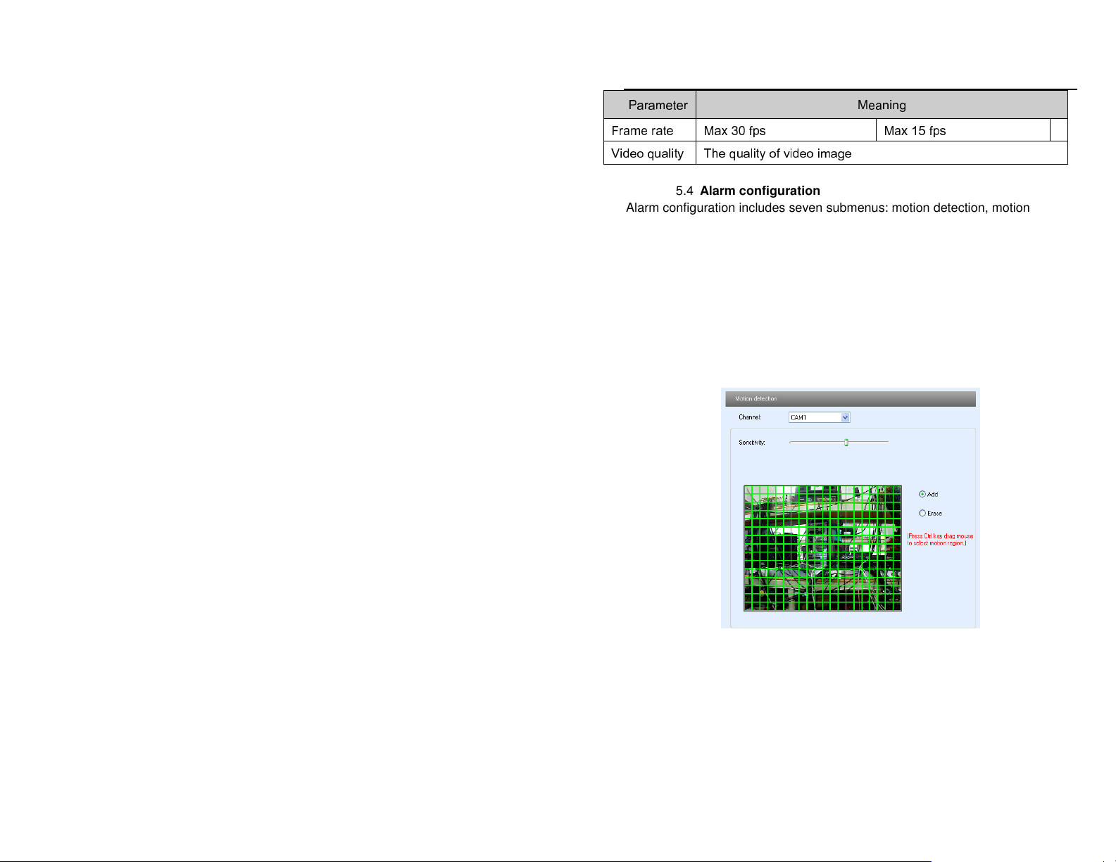
5.4.1 Motion detection
1. Enter into “Alarm configuration"--"Motion detection" refer to Figure 5-7:
2. Select the channel to set motion detection parameters at the "Channel
Number" pull down list.
3. Move the "Sensitivity" scroll bar to setup the motion detection sensitivity.
4. Select the "Add” option, press the "Ctrl" button and move mouse to select the
motion detection area; select the “Erase” option, move the mouse to clear all
motion detection areas.
5. Press the "Save" button to save the settings.
Fig 5-7 alarm configuration-- motion detection interface
5.4.2 Motion alarm
1. Enter into “Alarm configuration"-- "Motion alarm" refer to Figure 5-8:
2. Select "Enable alarm" check box, all functions under this interface will be
activated.
3. Select "Alarm output" in the "trigger alarm out” text box, it will trigger alarm if
the device connected to alarm is triggered.
4. Select "Trigger snap”, user should also select a matched channel; the alarm
31
Page 32

QSTC201/211 IP-CAMERA USER MANUAL
will be triggered when there was an alarm.
5. Select the matched channel in “Trigger PTZ” text box, select “To preset” or
“Start cruise”, when motion detection triggers alarm, the PTZ install stand of the
device will move to corresponding preset point or cruise line.
6. Press the "Save" button to save the settings.
Fig 5-8 alarm configuration—motion alarm interface
5.4.3 Motion Schedule
Enter into “Alarm configuration"-- "Motion schedule", refer to Figure 5-19:
Weekly schedule
User can set the record time from Monday to Sunday for recording everyday in
one week.
1. Select the channel which needs to be setup on the "Channel” pull down list.
Note: The length bar is for each day of the week divided into the 24 hours
of a day. You can use the mouse to click on the pane to set the record
hours. Green means area is selected. Blank means area is not selected.
2."Add": add the schedule record for a holiday
3."Delete": delete holiday schedule
Day schedule
User can set recording time for specific time of a special day, such as a holiday.
1. Select a special date at the "Date" pull down list, press "Add" button to add
that date to the list box on the right side, and move the scroll bar to set the record
schedule for that day.
2. Select a date in the list box on the right side, press "Delete" to remove the
schedule for that day.
32
Page 33

QSTC201/211 IP-CAMERA USER MANUAL
Press the "Save" button to save the settings.
Note: Day schedule is better than Week schedule.
Fig 5-9 alarm configuration—motion schedule interface
5.4.4 Sensor alarm
1. Enter into “Alarm configuration"--"Sensor alarm", refer to Figure 5-10:
2. Select the sensor which needs to be setup on the "Sensor" pull down list, and
set the sensor type: NO or NC.
3. Select the "Enable alarm" check box, all functions under this interface will be
activated.
4. Select the "Alarm output" in the "trigger alarm out” text box, it will trigger alarm
if the device connected to alarm is triggered.
5. Select the matched channel in “Trigger PTZ” text box, select “To preset” or
“Start cruise”, when sensor detection triggers alarm, the PTZ install stand of the
device will move to corresponding preset point or cruise line.
6. Select "Trigger snap”, user should also select a matched channel; the alarm
will be triggered when there was an alarm.
7. Press the "Save" button to save the settings.
33
Page 34

QSTC201/211 IP-CAMERA USER MANUAL
Fig 5-10 alarm configuration—sensor alarm interface
5.4.5 Sensor schedule
Enter into “Alarm configuration"—“Sensor schedule” refer to Figure 5-11:
Week schedule
User can set the recording time from Monday to Sunday for recording everyday
of a week.
1. Select the sensor which needs to be setup on the "Sensor" pull down list.
Note: The length bar is for each day of the week divided into the 24 hours
of a day. You can use the mouse to click on the pane to set the record
hours. Green means area is selected. Blank means area is not selected.
2."Add": add the schedule record for a holiday
3."Delete": delete holiday schedule
Day schedule
User can set recording time for specific time of a special day, such as a holiday.
1. Select a special date at the "Date" pull down list, press "Add" button to add
that date to the list box on the right side, and move the scroll bar to set the record
schedule for that day.
2. Select a date in the list box on the right side, press "Delete" to remove the
schedule for that day.
Press the "Save" button to save the settings.
Note: Day schedule is better than Week schedule.
34
Page 35

QSTC201/211 IP-CAMERA USER MANUAL
Fig 5-11 alarm configuration—sensor schedule interface
5.4.6 Other alarm
1. Enter into “Alarm configuration"— "Other alarm" refer to Figure 5-12:
2."Alarm type" default is video loss.
3. Select the channel which needs to be setup on the "Channel Number" pull
down list.
4. Select "Alarm out" in the "Trigger alarm out" textbox, which is optional.
5. Press the "Save" button to save the settings.
Fig 5-12 alarm configuration—other alarm interface
35
Page 36

QSTC201/211 IP-CAMERA USER MANUAL
5.4.7 Alarm out
1. Enter into “Alarm configuration"— "Alarm output" refer to Figure 5-13:
2. Select the alarm out number, alarm holding time and alarm name on the
"Alarm out”, “Alarm holding time” and “Name” pull down list respectively.
3. Press the "Save" button to save the settings.
Fig 5-13 alarm configuration—alarm out
Please refer to the following table for parameters and instructions of alarm out.
Parameter Meaning
Alarm out The alarm equipment which is connected to the device
Alarm holding time After triggered the holding time of the alarm output
Name The name (number) of the alarm
5.5 Network configuration
Network configuration includes four submenus: basic configuration, IP
configuration, wireless configuration and DDNS configuration.
5.5.1 Basic configuration
1. Enter into "Network configuration"--"Basic configuration", refer to Figure 5-14:
2. Input port number for IE access in the "HTTP Port" textbox.
3. Input the port number for audio & video transmission in the "Data Port"
textbox.
Fig 5-14 network configuration-- basic configuration interface
36
Page 37

QSTC201/211 IP-CAMERA USER MANUAL
4. Enable UPNP
Double-click the “My Network Places” icon on the desktop in PC, select “Show
icons for networked UPnP devices” in the “Network Tasks” list box, an
information window will pop up, click “YES” button, “Windows Components
Wizard” dialog box will pop up as shown in picture below, press “Next” to
continue. After finishing the installation of configured components, the UPnP
icons will display. Users can double-click certain icons and check the IP address
of the device
If “Show icons for networked UPnP devices” can’t display in the “Network Tasks”
list box, please follow the below steps:
Click “Tools”-- “Folder options”
Select the “Show common tasks in folders” in the “Tasks” check box, UPnP
icon will display.
37
Page 38

QSTC201/211 IP-CAMERA USER MANUAL
5.5.2 IP configuration
1. Enter into "Network configuration"--"IP configuration", refer to Figure 5-15:
There are three Options for setup IP: Static IP, dynamic IP and PPPOE.
2. Static IP: users manually input the IP address, subnet mask, gateway and
DNS.
3. Dynamic IP: router will distribute IP address to device automatically.
4. PPPOE: users manually input the user name and password for the network
connection that they get from their internet service provider.
5. Select the “Enable notifying change of IP”, an email will send to the appointed
mailbox automatically when Device’s IP address is changed.
6. Press the "Save" button to save the settings.
Note: If using dynamic IP address, user should search the wireless IP
address by wireless networking PC.
Fig 5-15 network configuration-- IP configuration interface
38
Page 39

QSTC201/211 IP-CAMERA USER MANUAL
Please refer to the following table for parameters and instructions of IP
configuration.
Parameter Meaning
Static IP
IP Address IP address of the server
Subnet mask Subnet mask of the server
Gateway Gateway address of the server
DNS server Domain name analytical server address of the server
Dynamic IP
Dynamic IP
Dynamic IPDynamic IP
Dynamic IP Router will distribute IP address automatically
PPPoE
PPPoE
PPPoEPPPoE
User name User name for broad-band connection
Password Password for broad-band connection
Change IP address through IP TOOL:
Click the device, then double-click or click “Net set” button to enter into
modify interface refer to Figure 5-16
Delete the initial data and input IP address which should exist in the same
LAN with PC
Click “OK” button to save the setting.
Note: dynamic IP can’t change the IP address
Fig 5-16 Change IP address
Note: If IP Tool search can’t find the device, please refer to chapter 3 IE
Remote Access.
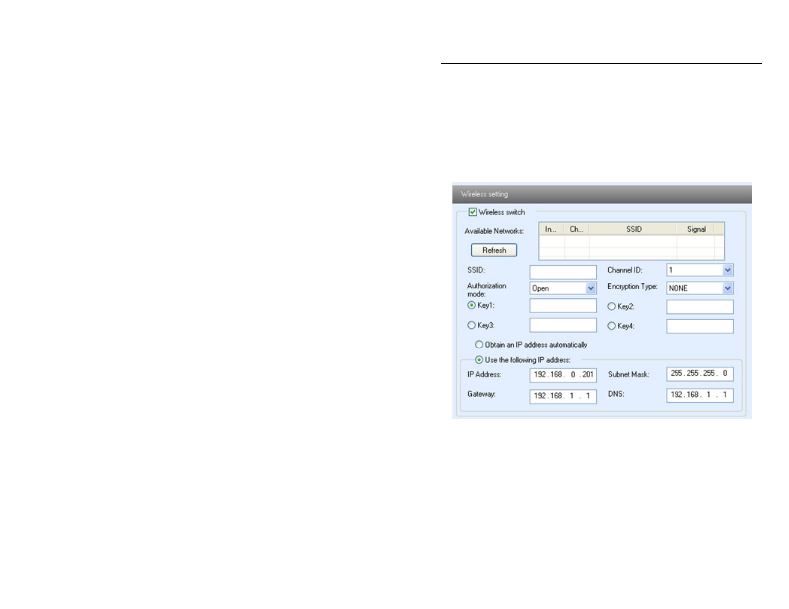
5.5.3 Wireless configuration
1. Enter into "Network configuration"--"Wireless configuration" refer to Figure
39
Page 40
QSTC201/211 IP-CAMERA USER MANUAL
5-17:
2. Select “wireless switch”, click “refresh” button, available wireless networks
found by device will display in the “Available network” list box on the right. User
can setup relative parameters according to available wireless networks.
3. SSID, channel, authentication mode and encrypt type, password are the same
as the user’s wireless router settings.
4. Select "Obtain IP address automatically", the device will distribute IP address,
subnet mask, gateway IP and DNS service; select “use the following IP address”,
user should manually input the IP address, subnet mask, gateway IP and DNS
service.
Fig 5-17 network configuration-- wireless configuration interface
5.5.4 DDNS configuration
1.
Enter into "Network configuration"-- "DDNS configuration" refer to Figure 5-18:
Note: The service of user selecting domain name is that video surveillance
server bands one domain name. First, users should register user name and
password to log on the website of service supplier, and then apply for a domain
name online for the server. After that, users can visit the server through inputting
the domain name at Internet Explorer terminal.
40
Page 41

QSTC201/211 IP-CAMERA USER MANUAL
Fig 5-18 network configuration-- DDNS configuration interface
2. Press the "Save" button to save the settings.
Please refer to the following table for parameters and instructions of DDNS
configuration.
Parameter Meaning
DDNS server Address of the website provided by domain name
supplier. The options: www.dyndns.com and
myq-see.com
User name Log in for the website of domain name supplier
Password Log in for the website of domain name supplier
Setting UP DDNS (Take myq-see.com as example)
NOTE: Before you setup MYQ-SEE DDNS, make sure you are able to remotely
view your DVR using your regular IP address.
1. From a Computer that is on same network as the IP Camera, go to
http://myq-see.com/
2. Click on New User
3. Do the registration
4. Create your Domain name and once it created, check the IP address listed
there is the same IP address that you are using before to connect to the DVR.
5. Now go to your IP Camera - DDNS Config
6. Enable DDNS
7. Host name: enter your domain name
8. User name: it is the email address you are using on the registration
9. Password : enter your password you are using on the registration
Press the Save button.
41
Page 42

QSTC201/211 IP-CAMERA USER MANUAL
5.6 User configuration
Enter into "User configuration" refer to Figure 5-19:
Fig 5-19 User configuration interface
Add user:
1. Click "Add" button, "Add user" dialog box opens, refer to Figure 5-20:
Fig 5-20 Add user dialog box
2. Input user name in "User Name" textbox (only letters).
Note: normal user and advanced user can preview live picture and
playback files (there is no difference between normal and advanced user
on this system; administrator not only can preview live picture and
playback files but have the right of remote setting.
3. Input characters in "Password" and "Confirm Password" textbox (letters or
numbers).
4. Input the MAC address of the PC in "Binding MAC address" textbox.
Note: After binding physical address to the IP-CAM, user can access the
42
Page 43

QSTC201/211 IP-CAMERA USER MANUAL
device on this PC in network only. If the MAC address was
““00:00:00:00:00:00” it can be connected to any computers.
5. Click “OK” button, new added user will be displayed in the user list.
Modify user:
1. Select the user who needs to modify password and physical address in the
user configuration list box.
2. Click “Modify” button, “Modify user” dialog box pops up, refer to Figure 5-21:
Fig 5-21 Modify user dialog box
3. Input original password of this user in the “change password” text box
4. Input new password in the “New password” and “Confirmation” text box
5. Input computer’s physical address from which user accesses the server in the
“User PC MAC” text box
6. Click “OK” button, to complete modification of user’s password and binding
MAC address.
Delete user:
1. Select the user which needs to be deleted in the user configuration list box.
2. Click “Delete” button, a confirm dialog box pops up, click “OK” to delete the
user.
Note: The default super administrator can not be deleted.
43
Page 44
QSTC201/211 IP-CAMERA USER MANUAL
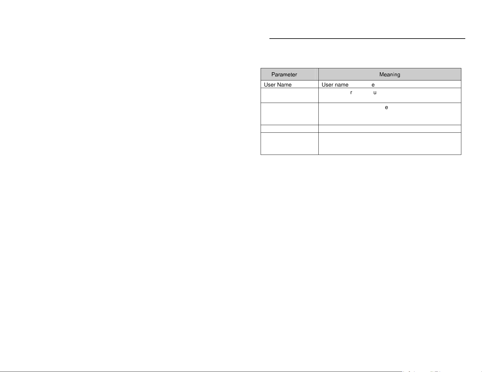
Please refer to the following table for parameters and instructions of user
configuration.
Parameter Meaning
User Name
User Type
Binding MAC
address
Password Password to log into the client terminal
Confirm Password
Enter into notification – mail configuration refer to Figure 5-22
1. From Email: sender’s e-mail address
2. User name and password: sender’s user name and password
3. Server address: SMTP name of sender
4. Select “This server requires a secure connection (SSL)”; user can setup mail
servers (such as Gmail) according to actual needs,
5. Receival email address list: add email address into the list
6. Receival email address: receiver’s e-mail address
7. after all parameters are setup, user can click “Test your account settings”, if
email is sent successfully, a “Test Successful” window will pop up, if not, users
can try other email addresses or check the settings.
Notice: If user changes the static IP into PPPoE, there will be an e-mail sent
to users’ mail box for notification of a new IP address.
5.7 Notification configuration
User name to operate the logon client end
Type of user: normal user, advanced user and super
administrator
The MAC addresses of users accessing the server
which should setup according to actual MAC address of
the server.
Password to log into the client terminal
Note: The confirmed password which is input by user
should conform to new password the user set.
44
Page 45

QSTC201/211 IP-CAMERA USER MANUAL
Fig 5-22 Notification configuration—mail configuration interface
5.8 Advanced configuration
Advanced configuration includes three submenus: upgrade, security
configuration and default configuration
5.8.1 Upgrade
Enter into advanced configuration—upgrade, refer to Figure 5-23:
1. Click “Browse” button to select the save path of the upgrade file
2. Click “upgrade server firmware” button, start upgrading the application
program
3. The device will restart automatically
Notice: user can’t disconnect from PC or close the IP-CAM during upgrade
Fig 5-23 advanced configuration—upgrade interface
5.8.2 Security configuration
Enter into advanced configuration—security configuration, refer to Figure 5-24:
1. Select “Enable IP address” check box, select “Deny the following IP address”,
input IP address in the IP address list box and click “Add” button, this IP address
will display in the list box; the step of “Allow the following IP address ” is the
same as “Deny the following IP address”.
2. Check the IP address which needs to be deleted in the IP address list box and
click “delete” button to delete the IP address.
3. Click "save" button to save the above setting.
Note: “Allow the following IP address” and “Deny the following IP
45
Page 46

QSTC201/211 IP-CAMERA USER MANUAL
address” can’t operate at the same time.
Fig 5-24 advanced configuration—security configuration interface
5.8.3 Default configuration
Enter into advanced configuration—default configuration refer to Figure 5-25:
Fig 5-25 advanced configuration—default configuration interface
Click “Load default” button to restore all system settings to original value, except
for IP address.
5.8.4 Reboot device
Enter into advanced configuration—reboot device refer to Figure 5-26:
Fig 5-26 advanced configuration—reboot device interface
Click “Reboot device” button to reboot the device.
46
Page 47

QSTC201/211 IP-CAMERA USER MANUAL
6
Video Search
Click “video search” icon, to search the images which are saved on the SD card
refer to Figure 6-1:
1. Select date in the “calendar”, check “motion detection” and/or “sensor”, click
“search” button, the snapped pictures that triggered the alarm will display in the
list box.
2. Double click a file name in the list box and you can check the snapped
pictures.
3. Click “save” icon select the save path for the file on PC.
Fig 6-1 video search interface
47
Page 48

QSTC201/211 IP-CAMERA USER MANUAL
7
Mobile Surveillance
This IP-CAMERA supports mobile surveillance by cell phones with Windows
mobile pro and Symbian operating systems. Below are the details of the
supported versions. Please check the operation system version of mobile phone
before using.
Operation system
Operation system Compatibility
Operation systemOperation system
Windows Mobile 2003 for Smartphone not supported
Windows Mobile 2003 for Pocket PC supported
Windows Mobile 5.0 for Smartphone not supported
Windows Mobile 5.0 for Pocket PC Phone
Edition
Windows Mobile 5.0 for Pocket PC supported
Windows Mobile 6 Standard not supported
Windows Mobile 6 Professional supported
Windows Mobile 6 Classic supported
Symbian S40 not supported
Symbian UIQ not supported
Symbian S80 not supported
Symbian S60 1st Edition-Symbian OS v6.1 supported
Symbian S60 2nd Edition-Symbian OS v7.0s supported
Symbian S60 2nd Edition with FP1-Symbian
OS v7.0s enhanced
Symbian S60 2nd Edition with FP2-Symbian
OS v8.0a
Symbian S60 2nd Edition with FP3-Symbian
OS v8.1
Symbian S60 3rd Edition-Symbian OS v9.1 supported
Symbian S60 3rd Edition with FP1-Symbian
OS v9.2
Symbian S60 3rd Edition with FP2-Symbian supported
Compatibility
CompatibilityCompatibility
supported
supported
supported
supported
supported
48
Page 49

QSTC201/211 IP-CAMERA USER MANUAL
OS v9.3
Symbian S60 5th Edition-Symbian OS v9.4 supported
Symbian S60 5.1 Edition-Symbian OS v9.5 supported
7.1 Accessing by Phones with Windows Mobile Pro
Please use cell phones or PDAs with WinCE versions supported by this unit.
First activate the network access on the mobile phone, and then run “Internet Explorer”.
STEP 1: Input the public IP address you need to use to connect as shown below:
STEP 2: Click on the software name. A dialog box will pop up.
STEP 3: Click “Yes” to download and install.
49
Page 50

QSTC201/211 IP-CAMERA USER MANUAL
STEP 4: PCam will be opened after installed.
STEP 5: Input the server’s address, ID, and password respectively in the columns of
“Server”, “User”, and “Password”. Then click “Go” to login to the DVR. It will show the
picture if accessed successfully.
STEP 6: Camera 1 is the default display after login. Change the camera in the drop down
menu of “Channel”.
50
Page 51

QSTC201/211 IP-CAMERA USER MANUAL
Note: User name and password here are the same as that used on the
DVR. The defaults are user name “admin” and password “123456”.
7.2 Accessing by Phones with Symbian
Please use smart phones or PDAs with Symbian version supported by this unit.
STEP 1: First enable the network access on mobile phone, and then run Web browser.
STEP 2: Input the DVR server’s IP address in a new-built bookmark. Click this bookmark
to connect with the DVR.
STEP 3: A welcome window will pop up with a link to download the software. Click “install
package” to download.
STEP 4: The security window will pop up after downloaded and ask if you want to install
the package. Click YES to install.
51
Page 52

QSTC201/211 IP-CAMERA USER MANUAL
STEP 5: A Scam shortcut icon appears on the system menu after finished.
STEP 6: Run Scam program.
STEP 7: Click Options--->Settings to enter login interface.
52
Page 53

QSTC201/211 IP-CAMERA USER MANUAL
STEP 8: Input the server’s address, ID and password respectively. Then click OK to login
to the DVR.
STEP 9: It will show the camera after accessing successfully.
Note: User name and password here are the same with that used on the
53
Page 54

QSTC201/211 IP-CAMERA USER MANUAL
DVR. The defaults are user name “admin” and password “123456”.
7.3 Accessing from iPhones
At present, the software only supports iPhone os2.2 and above, if phone
firmware is lower than this version please upgrade it. Below is the operation
method for accessing from iPhones:
Step1:Enter into App Store function on the iPhone:
Step 2: Enable “search” function to search for “SuperCam”, the required
program will be displayed on the top of search box:
54
Page 55

QSTC201/211 IP-CAMERA USER MANUAL
Step 3: Click SuperCam, to enter into “introduce” interface and click FREE”, it will
change into “INSTALL”
Step 4: Enter into iTunes Store password, click “OK” the below interface will
55
Page 56

QSTC201/211 IP-CAMERA USER MANUAL
display:
Note: if this is the first time you are operating please enter your user ID; if
you do not have a Store account, you will need to create one.
Step 5: Download the program and install it. After installing, the SuperCam icon
will display. Click this icon, the program interface will appear
Step 6: Click “System setting”, to enter into login interface. Enter server’s IP
address (or domain name), user’s ID and password. Click Back to save.
56
Page 57

QSTC201/211 IP-CAMERA USER MANUAL
Step 7: Click Live View, the default Cam1 picture will be displayed. Click to
capture picture. Click to enter PTZ mode.
57
Page 58

QSTC201/211 IP-CAMERA USER MANUAL
Step 8: Click Image View on program interface to view the captured picture. Click
or to switch to next or previous picture. Click to delete the current
picture.
Method two: Download SuperCam from iTunes, and synchronize it to iPhone
Step 1: Install iTunes on PC, and open it. Then connect iPhone to computer with
58
Page 59

QSTC201/211 IP-CAMERA USER MANUAL
“
the data cable. When prompt message appears click
interface. Input user’s ID and password.
Step 2: Click “iTunes Store” on the left column, search for “SuperCam”.
Continue”, refer to below
59
Page 60

QSTC201/211 IP-CAMERA USER MANUAL
Step3: Click searched “SuperCam”, refer to below picture
Step 4: Click“GET APP”, an input box will pop up. Enter user’s ID and password,
then press “Get”. It will download applicaton to the computer.
.
Step 5: Click your iphone device (here it is super iphone) in the left column, press
60
Page 61

QSTC201/211 IP-CAMERA USER MANUAL
“Applications”. Check ”Sync applications” and “SuperCam”. Then click “Apply”
in the lower-right corner, and wait for installation to finish.
Step 6: After installation finishes, return to main interface of iPhone, where the
camera icon will be displayed.
Step 7: Click camera icon; the program interface will appear. The following setting
steps are the same as method one “Step 5, 6, 7, 8”.
61
Page 62

QSTC201/211 IP-CAMERA USER MANUAL
8
Questions & Answers
1. Q: I forgot the password, how can I reset it?
A:Press “RESET” button for 4 seconds to restore to default status.
Note: Default IP: 192.168.0.201
User name: admin
Password: 123456
2. Q
::::
I can not connect to devices through IE browser, what can I do to solve
the problem?
A: Please check the network cable connections and make sure they are
connected well.
B: IP is not available. Reset the IP and make sure it is correct.
C: Web port number is being blocked by service provider or being used by
another device: try using a different port number.
D: If the above do not help try restoring default settings by pressing “RESET”
button for 3—5 seconds.
Note: default IP: 192.168.11.201,mask number: 255.255.255.0
3. Q
::::
IP tool search can not find devices, what can be stopping it?
A:It may be blocked by the anti-virus software in your computer. Please turn off
the anti-virus program and try to search for device again. Also make sure that
the PC and IP Camera are on the same network (connected to the same router)
4. Q:IE Can not download ActiveX control, how do I work around this?
a. If the IE browser is blocking ActiveX please do the following setup:
Open IE browser. Click Tools-----Internet Options….
62
Page 63

QSTC201/211 IP-CAMERA USER MANUAL
select Security------Custom Level….refer to Fig 4-1
Fig 4-1 Fig 4-2
Enable all the sub options under “ActiveX controls and plug-ins”, refer to Fig
4-2
then click ok to finish setup.
b. Other plug-ins or anti-virus could block ActiveX. Please turn off anti-virus
programs and disable other plug-ins using the Tools – Manage add-ons option.
After you install the ActiveX control you can turn the other plug-ins back on until
you find the one that was causing the problem.
5. Q
::::
I am not getting any sound, what is wrong?
A:Make sure audio cable is firmly attached to camera. Please re-connect and try
again.
B: Right click on the camera’s image on the screen and select the audio option to
enable it.
63
Page 64

QSTC201/211 IP-CAMERA USER MANUAL
::::
6. Q
A: 1. Connect camera to the Router using the network cable provided
2. Make sure the PC is connected to the same Router
3. Check the IP address of the Router by running IPCONFIG from the PC ( go to command
prompt and type in ipconfig). Note the ip address. As an example here the IP is 192.168.1.100
4. Install the CMS program.
5. Run IP TOOL. Default login is system and password is 123456
6. This tool will detect the IP camera automatically and show the IP address of the camera. By
default the IP address of Camera is 192.168.0.201. Based on the example above, the IP of the
Network is 192.168.1.100. So in this case we need to change the IP of the camera to 192.168.1.201.
To do this, right click on it and choose Network setup and change the IP address and change the
gateway to 192.168.1.1
7. Open Internet Explorer, enter the camera IP which is 192.168.1.201 on the address bar.
8. You will get the login screen and just enter 123456 for password.
How can I set this IP Camera up on a wireless router?
9. To setup the wireless, click on System Config on the bottom right. Then click on Wireless
config from the menu on the left side.
10. Check the Wireless Switch
11. Click on Refresh. It should detect all the Routers within range. Select your router.
12. On the SSID it should come up with all Router’s information, and if your Router is encrypted,
you have to put your Key, and leave the option to use the following IP defaulted to 192.168.1.201.
Click on Save.
13. Now you can unplug the network cable and then you can move the camera to wherever
you want as long its still within the range of the wireless router.
14. Within the same network you should be able to login to this camera using the same IP of
192.168.1.201
64
Page 65

QSTC201/211 IP-CAMERA USER MANUAL
15. If you want to remotely view this camera from outside the network, you need to forward port
80 and 9008 to the IP address of the camera in the Router. (There are complete instructions on how
to do this in the manual).
7. Q
::::
I can not connect to a wireless router, what can I try?
A: Check the status of the wireless router. Please make sure the router is open
or enabled.
B: Check the router and the device port. Please make sure the router setup is
using the correct device port.
65
Page 66

QSTC201/211 IP-CAMERA USER MANUAL
9
Specifications
66
Page 67

QSTC201/211 IP-CAMERA USER MANUAL
67
Page 68

QSTC201/211 IP-CAMERA USER MANUAL
10
Q-See Product Warranty
Thank you for choosing our products.
All of our products users have a conditional free warranty repair service for
hardware within 12 months starting from purchase date, and a free exchange
service within one month (valid for manufacturing defects). Permanent
upgrading service is provided for the software.
Liability Exclusions:
Any product malfunction, abnormalities in operation or damage caused by
following reasons are not within the free service scope of our company. Please
select payable service.
(1) Equipment damage caused by improper operation
(2) Improper environment and conditions in/on which the equipment operates,
e.g., improper power, environment temperature, humidity and lightening strike
etc. that cause equipment damage.
(3) Damage caused by acts of nature: earthquake and fire etc.
(4) Equipment damage caused by the maintenance of personnel not authorized
by our company.
(5) Product sold over 12 months ago.
In order to provide various services to you, please complete registration
procedure after you purchase the product. Cut off or copy User’s Information
Card and fax or mail it to us after the card is filled in. You can also register the
product by going to the www.q-see.com website and clicking on the Register
link.
If you have questions:
Mailing Address: Customer Service:
DPS Inc. Phone: 877-998-3440 x 538
8015 E. Crystal Dr Email: cs@dpsi-usa.com
Anaheim, CA 92807 Live Chat from our Website
Website: Tech Support:
http://www.q-see.com Phone: 877-998-3440 x 539
Fax: Email: ts@dpsi-usa.com
714-998-3509 Live Chat from our Website
Contact Us:
68
Page 69

QSTC201/211 IP-CAMERA USER MANUAL
Number of
Customer Information Card
User’s Name Mr./Mrs.
Company
Name
Postal
Address
Postal code
Phone
Number
E-mail
Model
Product
Serial Number
of Product
Purchase
Date
Distributor
69
Page 70

QSTC201/211 IP-CAMERA USER MANUAL
The material in this document is the intellectual property of our company.
No part of this manual may be reproduced, copied, translated, transmitted, or
published in any form or by any means without our company’s prior written
permission.
1. Our products are under continual improvement and we reserve the right to make
changes without notice. But no guarantee is given as to the correctness of its
contents.
2. We do not accept any responsibility for any harm caused by using our product.
3. The product picture may differ from the actual product, which is only for your
reference. The accessories will probably be different according to the different selling
areas. For details of accessories, please refer to your local distributor.
Copyright reserved
70
 Loading...