

Page 1

User Manual
MODEL QSDT8PCRC
MODEL QSDT8PCDP
MODEL QSDT16PCRC
8 and 16 Channel H264 Real Time Recording
PC-Based Network DVR PCI Cards
1
Page 2
Thank You for Choosing a Q-See Product!
All of our products are backed by a conditional service warranty covering all hardware for 12
months from the date of purchase. Additionally, our products also come with a free exchange
policy that covers all manufacturing defects for one month from the date of purchase.
Permanent upgrading service is provided for the software and is available at www.Q-See.com.
Be certain to make the most of your warranty by completing the registration form online. In
addition to warranty and technical support benefits, you’ll receive notifications of product
updates along with free downloadable firmware updates for your DVR. Register today at
www.Q-See.com!
About this Manual
This manual is written for the QSDT8PCRC, QSDT8PCDP and QSDT16PCRP security
surveillance video capture cards. This manual was accurate at the time it was completed.
However, because of our ongoing effort to constantly improve our products, additional
features and functions may have been added since that time and on-screen displays may
change. We encourage you to visit our website at www.Q-see.com to check for the latest
firmware updates and product announcements.
Throughout the manual we have highlighted warnings and other important information that will
assist you in operating your new system in a safe and trouble-free manner. Please take the
time to read and follow all instructions and pay attention to alerts as shown below:
Please see the back of this manual for exclusions.
© 2010, 2011 Q-See. Reproduction in whole or in part without written permission is
prohibited. All rights reserved. This manual and software and hardware described herein, in
whole or in part, may not be reproduced, translated, or reduced to any machine-readable
form without prior written approval.
Trademarks: All brand names and products are trademarks or registered trademarks of their
respective owners.
Q-See is a registered trademark of DPS, Inc.
Disclaimer: The information in this document is subject to change without notice. The
manufacturer makes no representations or warranties, either express or implied, of any kind
with respect to completeness of its contents.
Manufacturer shall not be liable for any damages whatsoever from misuse of this product.
IMPORTANT! Red boxes with this icon indicate warnings. To prevent
possible injury or damage to the product, read all warnings before use.
NOTE! Text in blue boxes with the Information icon offer additional guidance
and explanations about how to make the most out of your card.
Rev. 1.0 5/25/2011
2 3
Page 3

TABLE OF CONTENTS
1. Introduction 8
Features and Specifications 8
6. Recording, Playback and Record Search 26
6.1 Recording Configuration 26
Basic Configuration 27
Record Status Panel 28
2. System Requirements and Specifications 10
2.1 System Requirements 10
QSDT8PCRP & QSDT8PCDP 10
QSDT16PCRP 10
2.2 System Specifications 11
3. Video Capture Card Hardware and Connections 12
3.1 QSDT8PCDP Card 12
Video and Audio Pin Layout 13
Connecting Multiple Cards 13
3.2 QSDT8PCRP Card 14
Video and Audio Pin Layout 15
Connecting Multiple Cards 15
3.3 QSDT16PCRP Card 16
Video and Audio Pin Layout 17
Connecting Multiple Cards 18
3.4 Connecting a PTZ Camera 19
4. Installing the SuperDVR Software 20
4.1 Installing the Software 20
4.2 User Account Control for Windows Vista and Windows 7 22
5. Basic operation 24
5.1 Log In 24
5.2 Display Control Panel 25
Display Modes 25
Auto Dwell Display 25
Page Flip 25
5.3 Other Controls 25
Snapshot 25
Urgent Record 25
6.2 Recording Modes 28
Manual Record Mode 28
Sensor Alarm Record Mode 28
Motion Detection Record Mode 28
Schedule Recording 29
6.3 Recording to Hard Drive 31
6.4 Record Search and Playback 32
Record Search 33
Playback 34
6.5 Other Functions 35
File Backup 35
Deleting Recorded Files 36
Capture Pictures 36
Digital Image Zoom 38
7. System Settings 39
7.1 Basic Configuration 40
Camera Display Settings 40
Video Configuration 41
7.2 Alarm Configuration 42
Alarm Types 42
Triggered Actions 43
7.3 E-map Configuration 45
Using the E-Map 46
7.4 User Configuration 47
User Rights 47
Add User 48
8. P.T.Z. Cameras 49
8.1 P.T.Z Control Configuration 49
Protocol Setup 49
Serial Ports Setup 50
8.2 PTZ Operation 50
Preset and Group Select 51
4 5
Page 4

9. Remote Surveillance & Playback 52
9.1 Remote Live Surveillance 52
Remote Surveillance Server Configuration 52
9.2 Configuring Router for Remote Access 53
Part 1: Find Out the IP Address of the System 53
Part 2: Determine the Number of Routers on the Network 54
Part 3: Simple Port Forwarding 56
Part 4: Setting Up DMZ in Router 2 61
9.3 DDNS (Dynamic Domain Name Service) 62
Setting up DDNS 62
9.4 Accessing the DVR Using Internet Explorer 63
User Account Control for Windows Vista and Windows 7 63
Accessing the Internet Explorer Client 68
9.5 Remote Playback 71
Record Playback and Control 71
Remote Backup 71
9.6 System Setup 74
Basic Configuration 74
Alarm Setup 75
Camera Setup 76
Schedule Configuration 76
Alarm Configuration 77
Record Configuration 77
Storage Disk 78
Motion Configuration 78
E-mail Configuration 78
APPENDIX 97
Frequently Asked Questions 97
Other Questions 100
Quick Start Instructions 102
Installation Instructions 102
Troubleshooting 102
Function Tree 104
System Configuration Tree 105
IE Client Function Tree 106
Remote Playback Function tree 107
Q-SEE PRODUCT WARRANTY 108
Questions or Comments? Contact Us 109
9.7 P.T.Z Configuration 80
Protocol Setup 80
Serial Port Setup 80
10. Mobile Surveillance 81
10.1 Windows Mobile Pro 81
10.2 Symbian 83
10.3 iPhone and iPad 85
Installing Through the iPhone or iPad 85
Installing Through PC or Macintosh Computer 87
Operating Instructions for iPhone/iPad 88
10.4 Android 92
Software Installation 92
6 7
Page 5

INTRODUCTION
CHAPTER 1
FEATURES AND SPECIFICATIONS
The QSDT8PCRC, QSDT8PCDP and QSDT16PCRP 8- and 16-Channel cards allow you
to add surveillance capabilities to your computer. They use a H.264 hardware compression
format which provides maximum file storage with the least amount of signal loss possible.
Monitor and record up to four channels in CIF resolution with synchronous audio and video
compression and transmission. Remotely monitor your system through your network, over the
Internet or using select mobile devices.
The first chapters will cover the installation of your card as well as any connections you may
wish to make. Later chapters will guide you through the installation of the SuperDVR 6.3
software which supports these cards along with how to operate the hardware and software
together.
Please make sure you operate the products strictly in accordance with applicable laws along
with following the guidance of this manual to maintain the stability of your digital surveillance
system.
This product offers the following features:
Motion detection mode
Motion detection areas are adjustable with a maximum 16 areas for each channel. Users can
also set motion detection sensitivity for each channel. The system begins to record only when
motion is detected on the channel and after motion stops it will stop recording after a certain
time period, which is adjustable by users.
Sensor alarm record mode
The system has an external alarm dongle which enables the system to support alarm input
and output.
Recycling record mode
Users can set recording storage sequence for hard drive partitions. The recording storage will
automatically switch to the next partition when the current one is full. If all the partitions are full
and recycling record mode is enabled, the oldest recorded data will be covered by new data.
Users can also set hard drive minimum storage alarm. Then once the present storage space
is less than the minimum storage and recycling record mode is not enabled, recording will
automatically stop.
P.T.Z control function
Supports many protocols: PelcoD, PelcoP, DSCP, DH-SD, Lilian, Minking, Neon, Star, VIDO,
and VISCA. Users can control multiple speed domes and integrative cameras, including pan,
tilt, zoom, focus and iris adjustment for P.T.Z devices. Supports preset points and auto scan.
User management
Different users have different rights, user names and passwords, to ensure system security.
Multi-channel display
Supports different multi-channel display modes, full screen display and auto dwell display.
Also:
One PC can fit 1, 2 or 4 cards of the same model to control up to 32 channels total
n
n Supports 320x240, 704x480 (NTSC), 352x288, 704x576 (PAL) standard resolutions.
n Image color is adjustable for each channel, including contrast, brightness, hue and
saturation.
n
H.264 compression format greatly reduces HDD usage.
n Powerful video playback functions, including pause, stop, fast-forward, single-frame play
and image capture.
n
Supports advanced search mode. Users can search by date/time, camera, record mode,
and random combination of the three methods.
n Supports recorded file backup, delete by date/time, camera.
n Conveniently extend system functions through software upgrades.
n Supports multiple languages, including English, German, Spanish, Portuguese, Chinese
(Traditional), and other customized languages.
n CPU and storage resource saving by advanced technology
n Remote Surveillance and P.T.Z control through LAN, Intranet, and Internet.
n Supports alarm pre-record.
n Supports buzzer, e-mail alarm out.
n Can greatly decrease fragmented files while using NTFS partition.
n User-friendly graphical user interface.
8 9
Page 6
SYSTEM REQUIREMENTS AND
CHAPTER 2
SPECIFICATIONS
2.1 SYSTEM REQUIREMENTS
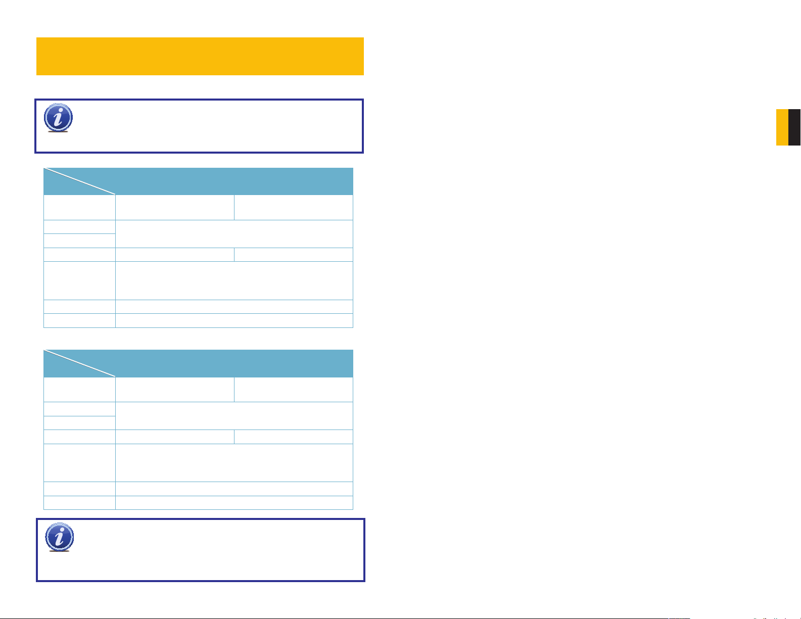
NOTE! If recorded disk partition’s format is FAT32 and the system has run
for a long time, the system will create a lot of data fragments that may result
10 to 30 days. We strongly suggest that you use NTFS format for recording disk partition.
QSDT8PCRP & QSDT8PCDP
Card
PC Module
CPU
Motherboard
Hard Drive
RAM 1GB minimum 2GB minimum
Video Card
OS Win 2000(SP4 above) /Win XP(SP2 above) /VISTA/Win7
DirectX 9.0
in system running slowly. It’s recommended to run a disk defragmenter every
Single QSDT8PCRC or
QSDT8PCDP card
Intel P4 2.8Ghz minimum or
later Intel processor
Intel with Intel system chipset
500GB minimum
Supports MOST* AGP and PCI-E Video Cards with 256MB of
RAM or more with full Direct Draw support.
*Some newer PCI-E cards are not yet supported
Two QSDT8PCRC or
QSDT8PCDP cards
Intel Dual-core 2.8Ghz
minimum
2.2 SYSTEM SPECIFICATIONS
• Format: NTSC /PAL
• Resolution
QSDT8PCRP & QSDT16PCRP: 320×240 @ 30FPS (NTSC) / 352×288 @ 25FPS (PAL)
704x480 @ 7FPS (NTSC) / 704x576 @ 6FPS (PAL)
QSDT8PCDP: 704x480 @ 30FPS (NTSC) / 704x576 @ 25FPS (PAL)
• Screen set: resolution 1024×768, color quality 16 bits or 32 bits.
• Compression format: H.264 Hardware
• Compression code rate: 50kbps – 1.2Mbps.
• Data format: H.264 (files saved as AVI)
• Input: D type connector
• PTZ: Protocol Configurable, Remote Control Capability
• Remote Access Software: Internet Explorer
• Interface: PCI
CHAPTER 2 SYSTEM REQUIREMENTS AND SPECIFICATIONS
QSDT16PCRP
Card
PC Module
CPU
Motherboard
Hard Drive
RAM 1GB minimum 2GB minimum
Video Card
OS Win 2000(SP4 above) /Win XP(SP2 above) /VISTA/Win7
DirectX 9.0
NOTE! We do not recommend AMD systems because the SuperDVR
program usually has problems communicating with the video card on the
system through the chipset on the AMD motherboard. There are often similar
problems with Intel processors on motherboards that use chipsets other then Intel, and
there are known issues with the Intel G31 chipset.
Single QSDT16PCRC card Two QSDT16PCRC cards
Intel P4 2.8Ghz minimum or
later Intel processor
Intel with Intel system chipset
500GB minimum
Supports MOST* AGP and PCI-E Video Cards with 256MB of
RAM or more with full Direct Draw support.
*Some newer PCI-E cards are not yet supported
Intel Dual-core 2.8Ghz
minimum
10 11
Page 7
VIDEO CAPTURE CARD
Video 5
GND
Video 6
GND
Video 7
GND
Video 8
GND
GND
Audio 5
Audio 6
Audio 7
Audio 8
Null
GND
PIN 1 2 3 4 5 6 7 8
PIN 9 10 11 12 13 14 15
P1
HARDWARE AND CONNECTIONS
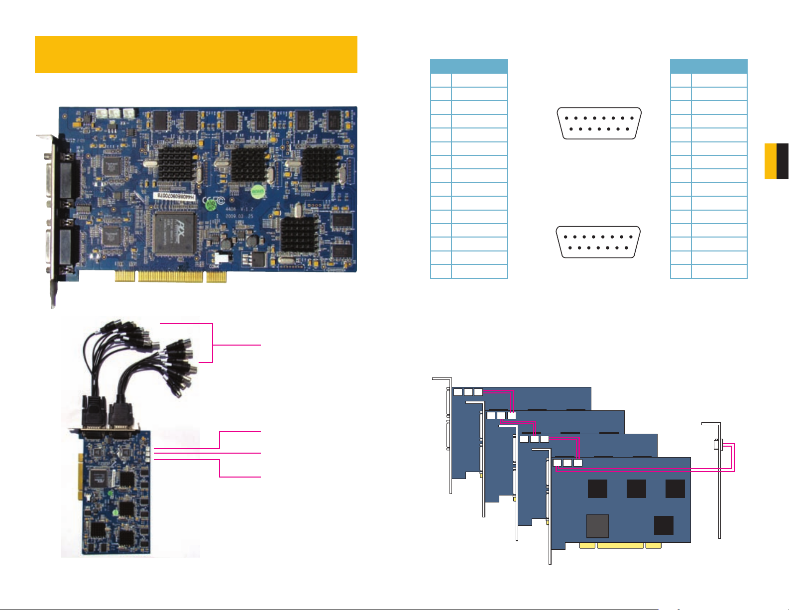
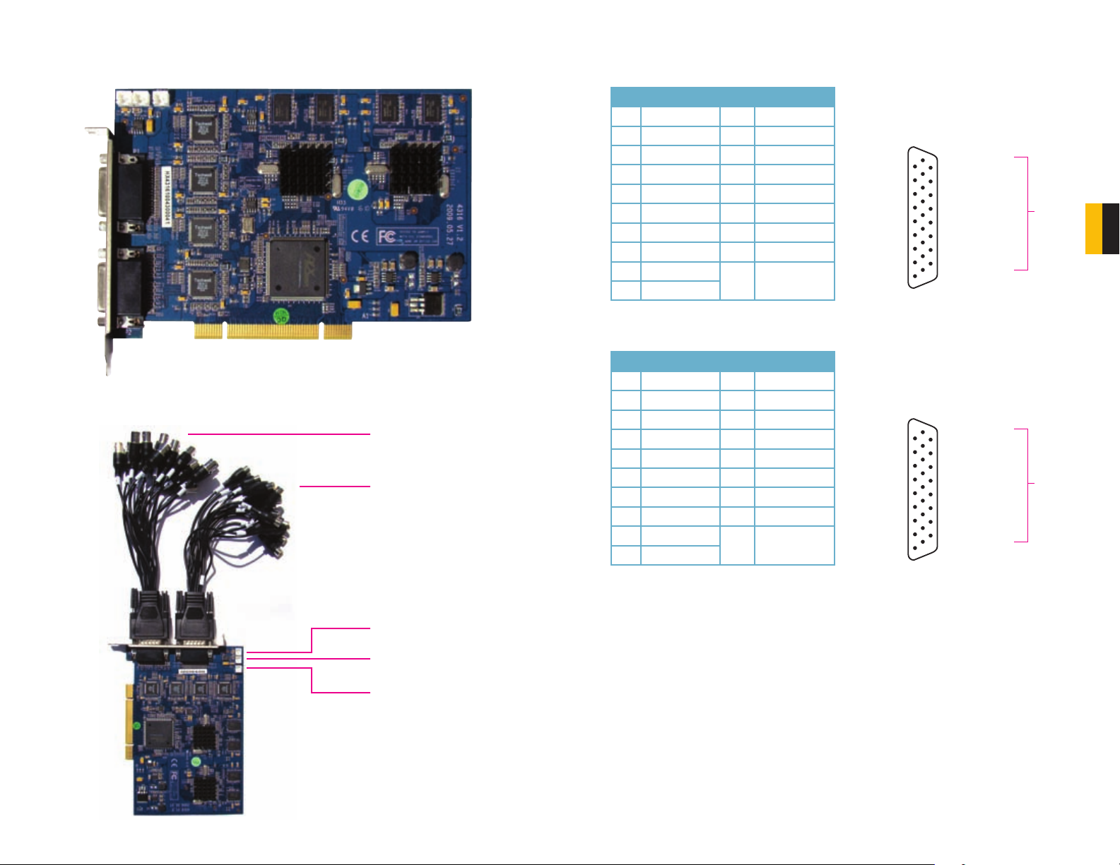
3.1 QSDT8PCDP CARD
PICTURE 3-1
CHAPTER 3
VIDEO AND AUDIO PIN LAYOUT
P1 P2
Pin Connection
1 VIDEO-5
2 GND
3 VIDEO-6
4 GND
5 VIDEO-7
6 GND
7 VIDEO-8
8 GND
9 GND
10 AUDIO-5
11 AUDIO-6
12 AUDIO-7
13 AUDIO-8
14 NULL
15 GND
P1
PIN 1 2 3 4 5 6 7 8
Video 5
GND
Video 6
GND
Video 7
GND
Video 8
GND
Audio 5
Audio 6
Audio 7
Audio 8
Null
PIN 9 10 11 12 13 14 15
P2
PIN 1 2 3 4 5 6 7 8
Video 1
GND
Video 2
GND
Video 3
GND
Video 4
GND
Audio 1
Audio 2
Audio 3
Audio 4
Null
GND
PIN 9 10 11 12 13 14 15
PICTURE 3-3
GND
GND
GND
Pin Connection
1 VIDEO-1
2 GND
3 VIDEO-2
4 GND
5 VIDEO-3
6 GND
7 VIDEO-4
8 GND
9 GND
10 AUDIO-1
11 AUDIO-2
12 AUDIO-3
13 AUDIO-4
14 NULL
15 GND
CHAPTER 3 VIDEO CAPTURE CARD HARDWARE AND CONNECTIONS
Audio In and
Video In Ports
(4 Each)
P1 P2
CON 1 Port
CON 2 Port
Spot Out Port
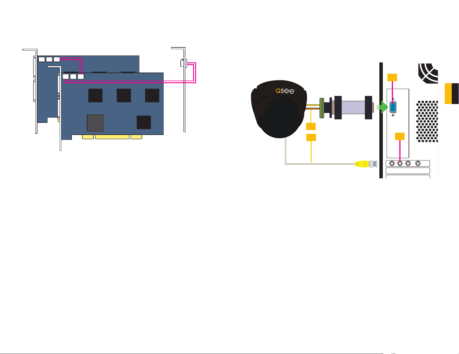
CONNECTING MULTIPLE CARDS
You may control up to 32 cameras by installing up to four QSDT8PCDP cards. You will need
to connect the cards in the manner shown below to use the Spot Out option.
Call
Monitor
Out
PICTURE 3-2
PICTURE 3-4
12 13
Page 8
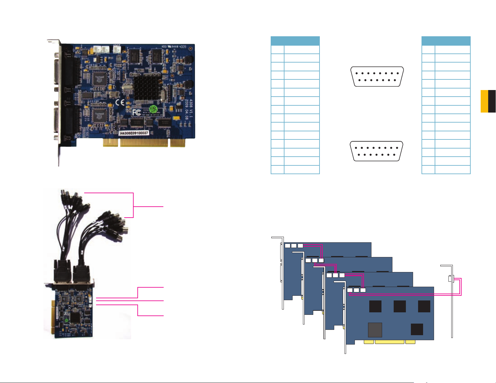
3.2 QSDT8PCRP CARD
Video 5
GND
Video 6
GND
Video 7
GND
Video 8
GND
GND
Audio 5
Audio 6
Audio 7
Audio 8
Null
GND
PIN 1 2 3 4 5 6 7 8
PIN 9 10 11 12 13 14 15
P1
PICTURE 3-5
Audio In and
Video In Ports
(4 Each)
VIDEO AND AUDIO PIN LAYOUT
P1 P2
Pin Connection
1 VIDEO-5
2 GND
3 VIDEO-6
4 GND
5 VIDEO-7
6 GND
7 VIDEO-8
8 GND
9 GND
10 AUDIO-5
11 AUDIO-6
12 AUDIO-7
13 AUDIO-8
14 NULL
15 GND
P1
PIN 1 2 3 4 5 6 7 8
Video 5
GND
Video 6
GND
Video 7
GND
Video 8
GND
Audio 5
Audio 6
Audio 7
Audio 8
Null
GND
PIN 9 10 11 12 13 14 15
P2
PIN 1 2 3 4 5 6 7 8
Video 1
GND
Video 2
GND
Video 3
GND
Video 4
GND
Audio 1
Audio 2
Audio 3
Audio 4
Null
GND
PIN 9 10 11 12 13 14 15
GND
GND
Pin Connection
1 VIDEO-1
2 GND
3 VIDEO-2
4 GND
5 VIDEO-3
6 GND
7 VIDEO-4
8 GND
9 GND
10 AUDIO-1
11 AUDIO-2
12 AUDIO-3
13 AUDIO-4
14 NULL
15 GND
PICTURE 3-7
CONNECTING MULTIPLE CARDS
You may control up to 32 cameras by installing up to four QSDT8PCRP cards. You will need
to connect the cards in the manner shown below to use the Spot Out option.
CHAPTER 3 VIDEO CAPTURE CARD HARDWARE AND CONNECTIONS
P2 P1
Call
Monitor
Out
CON 1 Port
CON 2 Port
Spot Out Port
PICTURE 3-6
PICTURE 3-8
14 15
Page 9
3.3 QSDT16PCRP CARD
1
2
3
4
5
6
7
8
9
Audio 2
Audio 4
Audio 6
Audio 8
Audio 10
Audio 12
Audio 14
Audio 15
Audio 16
19
20
21
22
23
24
25
26
Pin Pin
10
11
12
13
14
15
16
17
18
Audio 1
Audio 3
Audio 5
Audio 7
Audio 9
Audio 11
Audio 13
Null
Null
Pin
Ground
P1
PICTURE 3-9
P1P2
Video In Ports (8)
Audio In Ports (8)
CON 1 Port
VIDEO AND AUDIO PIN LAYOUT
P1
Pin Connection Pin Connection
1 AUDIO2 11 AUDIO3
2 AUDIO4 12 AUDIO5
3 AUDIO6 13 AUDIO7
4 AUDIO8 14 AUDIO9
5 AUDIO10 15 AUDIO11
6 AUDIO12 16 AUDIO13
7 AUDIO14 17 NULL
8 AUDIO15 18 NULL
9 AUDIO16
10 AUDIO1
P2
Pin Connection Pin Connection
1 VIDEO2 11 VIDEO3
2 VIDEO4 12 VIDEO5
3 VIDEO6 13 VIDEO7
4 VIDEO8 14 VIDEO9
5 VIDEO10 15 VIDEO11
6 VIDEO12 16 VIDEO13
7 VIDEO14 17 NULL
8 VIDEO15 18 NULL
9 VIDEO16
10 VIDEO1
1926
1926
GND
GND
P1
Pin Pin
Audio 2
1
Audio 4
2
Audio 6
3
Audio 8
4
Audio 10
5
Audio 12
6
Audio 14
7
Audio 15
8
Audio 16
9
Pin
10
11
12
13
14
15
16
17
18
Audio 1
Audio 3
Audio 5
Audio 7
Audio 9
Audio 11
Audio 13
Null
Null
19
20
21
22
23
24
25
26
P2
Pin Pin
Video 2
1
Video 4
2
Video 6
3
Video 8
4
Video 10
5
Video 12
6
Video 14
7
Video 15
8
Video 16
9
Pin
Video 1
10
Video 3
11
Video 5
12
Video 7
13
Video 9
14
Video 11
15
Video 13
16
Null
17
Null
18
PICTURE 3-11
19
20
21
22
23
24
25
26
Ground
Ground
CHAPTER 3 VIDEO CAPTURE CARD HARDWARE AND CONNECTIONS
CON 2 Port
Spot Out Port
PICTURE 3-10
16 17
Page 10
CONNECTING MULTIPLE CARDS
You may control up to 32 cameras by installing up to two QSDT16PCRP cards. You will need
to connect the cards in the manner shown below to use the Spot Out option.
Call
Monitor
Out
3.4 CONNECTING A PTZ CAMERA
In order to operate a PTZ camera from your card, you will need to have first installed the card
into a PCI slot within the computer and attached the video dongle.
You will also need an RS485 to RS232 (Serial) adapter as well as having a serial port on the
back of your PC.
PICTURE 3-12
PTZ Camera RS485 to
Serial Adapter
PC
2
1
3
PICTURE 3-13
STEP 1. Connect the RS485 cables from the PTZ camera to the RS485-to-Serial Adapter
STEP 2. Connect the Adapter to the serial port on the back of the PC
STEP 3. Connect the video line from the camera to any Video In port on the DVR card
(Item 4)
You may now connect your camera to a power source.
4
CHAPTER 3 VIDEO CAPTURE CARD HARDWARE AND CONNECTIONS
Please see Chapter 8 for instructions on operating the PTZ camera with the SuperDVR
software.
18 19
Page 11
INSTALLING THE SUPERDVR
SOFTWARE
CHAPTER 4
4.1 INSTALLING THE SOFTWARE
You will be controlling your security system using the SuperDVR software. It is compatible with
Windows 2000, XP, and both the 32 bit and 64 bit versions of Vista and Windows 7.
The SuperDVR software is included on the disk that comes packaged with your DVR card. It
can also be downloaded from our website at www.Q-See.com by simply searching for your
product and going to the Downloads section.
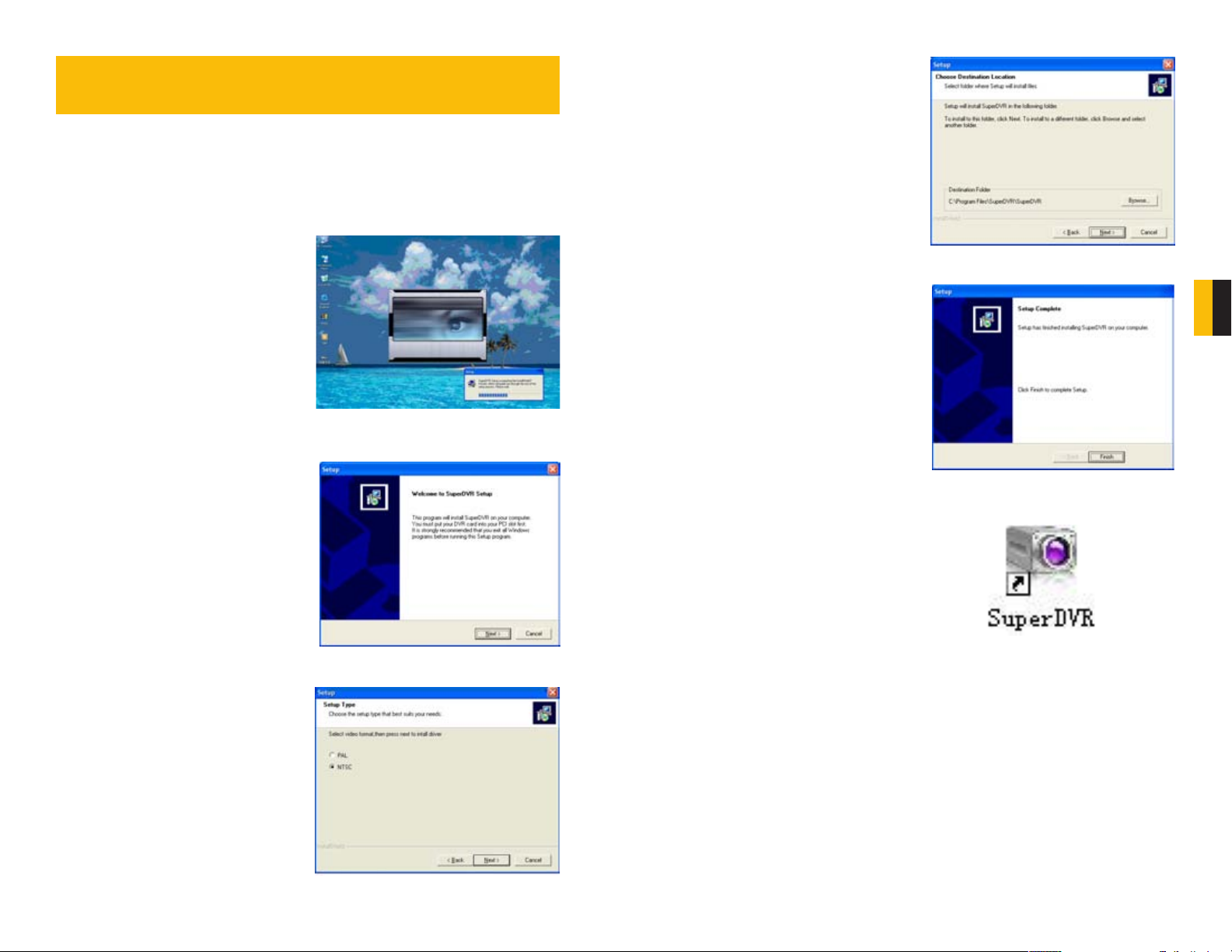
STEP 1. The software can be installed
from the CD by selecting the
appropriate button in the CD’s menu,
by copying the installer to your hard
drive and then double clicking to
begin the process.
PICTURE 4-1
STEP 2. Once the Setup window opens,
click Next to begin the installation.
STEP 4. Instruct the installer where you
want the software to be placed. Either
use the default location or select your
own. Click Next to continue.
PICTURE 4-4
CHAPTER 4 INSTALLING THE SUPERDVR SOFTWARE
STEP 5. Once the installation has
completed, you will be asked to press
the Finish button.
PICTURE 4-5
As part of the installation process, a shortcut
to the SuperDVR software will be placed on
your desktop.
You will need to restart your computer before
you can launch SuperDVR and begin setting
STEP 3. Select your video format. NTSC
is the standard in North America.
Click next to continue.
PICTURE 4-2
PICTURE 4-3
up your surveillance system.
PICTURE 4-6
20 21
Page 12
4.2 USER ACCOUNT CONTROL FOR WINDOWS VISTA AND WINDOWS 7
Some users of computers using Windows Vista or Windows 7 operating systems may receive
an error message informing of a codec that is missing or not installed. This conflict can be
resolved by turning off User Account Control (UAC).
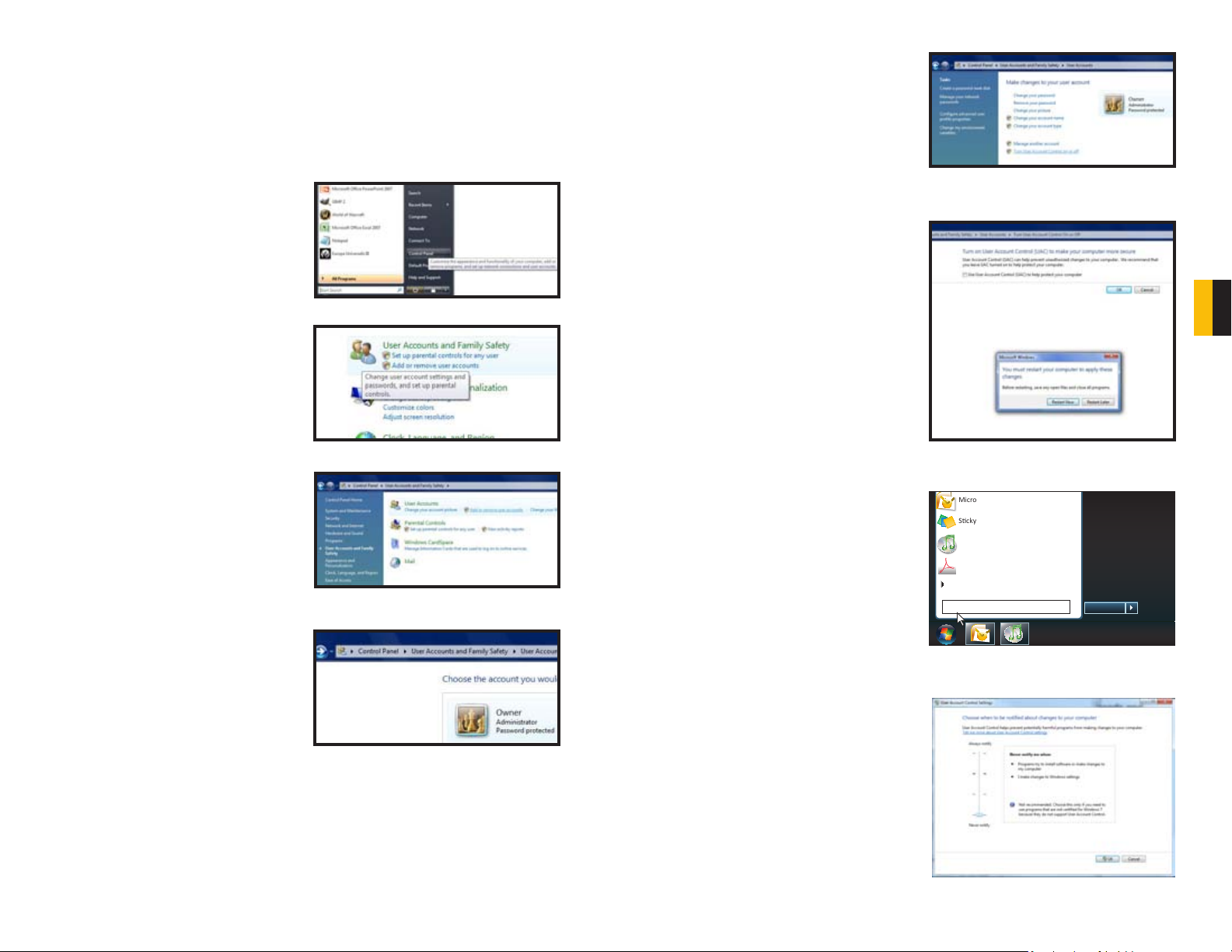
Windows Vista
1. Open the Control Panel (accessible by
clicking on the Windows icon in the
lower left of your screen.
PICTURE 4-7
2. Select User Accounts and Family
Safety.
5. Select Turn User Account Control
on or off
6. Uncheck the box next to “Use User
Account Control (UAC) to help protect
your computer.”
7. You will then be asked to restart your
computer for the change to take
effect.
PICTURE 4-11
CHAPTER 4 INSTALLING THE SUPERDVR SOFTWARE
3. Select “Add or Remove User
Account.”
4. Select the desired user account.
PICTURE 4-8
PICTURE 4-9
Windows 7
1. Open up the Start Menu (accessible by
clicking on the Windows icon in the
lower left of your screen.
2. Type “uac” into the search bar and hit
ENTER. The User Account Control
will open or you will be offered a link
to click to open it.
Microso Office Outlook 2007
Scky Notes
iTunes
Adobe Acrobat
All Programs
uac
PICTURE 4-12
Devices and Printers
Default Programs
Help and Support
Shut down
PICTURE 4-13
3. Move slider to lowest setting and press
PICTURE 4-10
OK.
PICTURE 4-14
22 23
Page 13
BASIC OPERATION
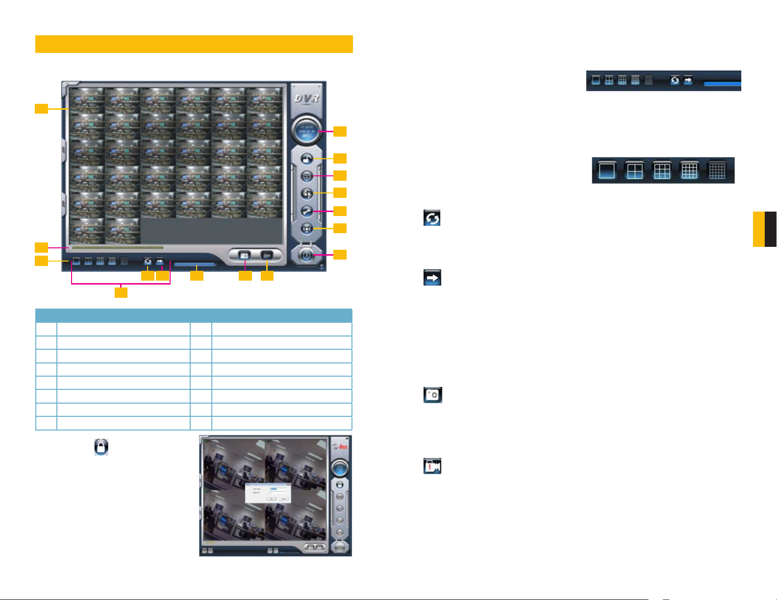
When you launch the SuperDVR program, it will open to the Main Display Interface which
will show the video feeds from the cameras as well as the Display Control Panel.
CHAPTER 5
1
5.2 DISPLAY CONTROL PANEL
The Display Control Panel includes the Display Mode buttons along with buttons which allow
you to cycle automatically or manually through individual or groups of channels.
Buttons currently in effect are highlighted.
The Drive Capacity Indicator Bar will fill in as
more files are recorded to the drive. When the
drive is at capacity, the bar will be red.
PICTURE 5-3
2
3
5 6 7 98
4
No. Item No. Item
1 Display Window 2 Record Status Panel
3 Display Modes 4 Display Control Panel
5 Dwell Time 6 Page Flip
7 Drive Capacity Indicator Bar 8 Snapshot
9 Urgent Record 10 Date and Time
11 Login 12 Emap
13 Search and Playback 14 Configurations
15 PTZ Control 16 Exit
5.1 LOG IN
Located on the left side of the Main Display
Interface, clicking on the lock icon will open
the Login window. Enter your user name and
password to access the controls. The default
user name is System with no password
required. You can add a password and create
other user accounts as described in Section
7.4 User Configuration.
PICTURE 5-1
10
11
12
13
14
15
16
DISPLAY MODES
Choose the number of channels you wish to view simultaneously. If you have fewer cameras
than portions of the screen, those channels without cameras will remain black.
Available modes are single-, four-, nine-. 16and 36-screen displays. The software will only
display the modes appropriate to the number
of cameras you have connected.
AUTO DWELL DISPLAY
If the Main Display is currently showing fewer channels than are available, you can have the
DVR automatically cycle through and show the feed from each camera or group of cameras
by selecting the button.
PAGE FLIP
This button allows you to manually cycle through the channels. Like the Auto Dwell feature, if
there are more channels available than are currently being displayed in a multi-screen display
mode, this button will take you to the next group of video feeds.
PICTURE 5-4
5.3 OTHER CONTROLS
Log In will be covered in the following section and the remaining operations on the left
hand side of the Main Display Interface will be covered in Chapter 7. The two remaining
functions are Snapshot and Urgent Record.
SNAPSHOT
Usable in single image display mode, pressing this button will take a series of still images
from the camera currently being displayed and will save them to a location on the hard drive.
Settings to determine the number of images (up to 32) as well as the location to where they
will be saved will be covered in Chapter 6.
URGENT RECORD
Clicking the Urgent Record icon will cause all cameras to begin recording regardless of their
schedule or recording mode. Video will be saved to the location designated by the user. Like
Snapshot, the settings for this feature will be covered in Chapter 6.
CHAPTER 5 BASIC OPERATION
PICTURE 5-2
24 25
Page 14
RECORDING, PLAYBACK AND
CHAPTER 6
RECORD SEARCH
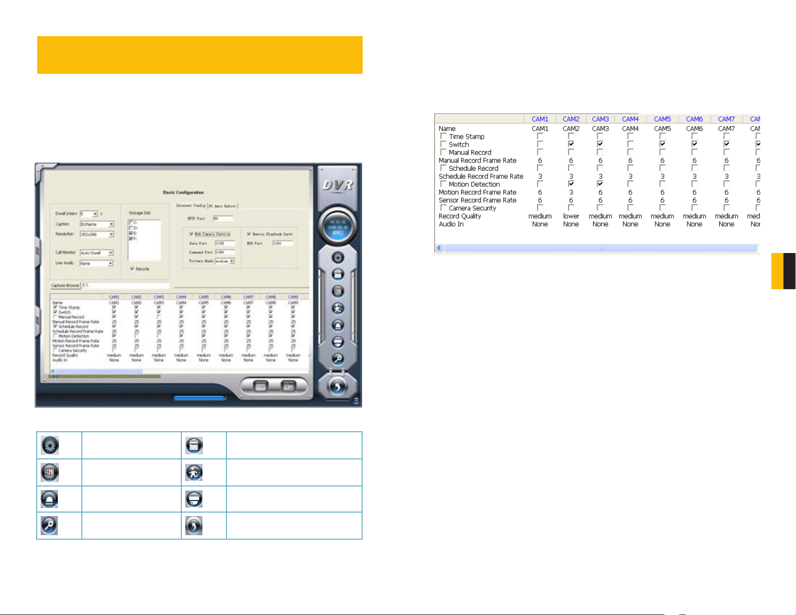
6.1 RECORDING CONFIGURATION
The system can be set to record in four different modes; scheduled recording, manual recording, motion detection and sensor alarm.
Once you have logged into your system, you can access the control settings through the
Configuration window by clicking on the wrench icon located on the left of the Main Display Interface.
Upon accessing the Configuration window, the icons on the left will change as will the contents of the Display Window.
PICTURE 6-1
Basic Configuration Schedule configuration
Video configuration Motion Detection Configuration
Alarm Configuration P.T.Z Configuration
User Configuration Save and Return
BASIC CONFIGURATION
The Record Panel, in the bottom half of the Basic Configuration page, allows users to set
recording modes along with other parameters for each camera. More than one recording
mode can be activated at one time.
It should be noted that the higher the recording quality and frame rate, the more space the
recorded file(s) will occupy on the hard drive.
CHAPTER 6 RECORDING, PLAYBACK AND RECORD SEARCH
PICTURE 6-2
Time Stamp - By selecting this option, the record date / time message appears in the
recorded file images.
Switch - Turns on corresponding cameras. If there is no camera on a channel, do not select
this option and you will save system resources.
Manual Record - Images from the selected camera will be recorded and saved all the time
(24 hour recording).
Manual Recording Frame Rate - Select the recording frame rate for manual record mode.
Schedule Record - This option allows you to record on a set schedule.
Schedule Record Frame Rate - Select Schedule Recording frame rate.
Motion Detection - By selecting this option, users can set the selected channels to record
when motion is detected in front of the camera.
Motion Record Frame Rate - Select recording frame rate for Motion Detection record mode.
Sensor Record Frame Rate - If sensors are utilized to trigger recording, users can select
recording frame rate here.
Camera Security - Users are divided into three types: Normal user, Power user and
Administrator. By selecting this option, only administrators can see the selected channels.
Record Quality - Select recording image quality here.
Audio In - SuperDVR 6.3 can support one channel of microphone audio input signal on the
PC motherboard and any audio inputs that are on the card if any. Users can choose one video
channel for each available audio input.
For the purposes of this chapter, we will only be concerned with; Schedule Configuration,
Video Configuration and Motion Detection Configuration. The remaining functions will be
covered in Chapter 7.
26 27
Page 15
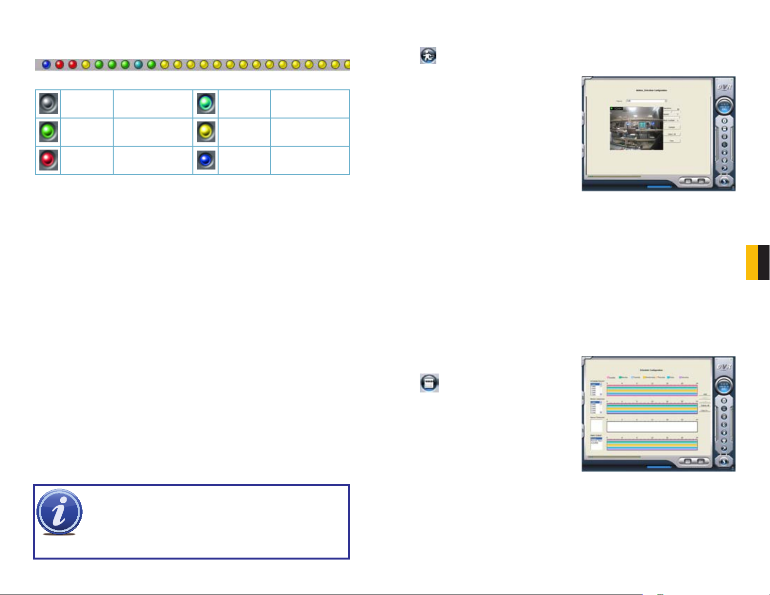
RECORD STATUS PANEL
A series of indicator lights will convey the recording status of each attached camera.
PICTURE 6-3
Grey Normal Light Green Manual Record
Dark Green Schedule Record Yellow
Red Sensor Alarm Record Blue Video Loss State
If an indicator light color turns, it means there is an alarm output.
Motion Detection
Record
6.2 RECORDING MODES
As mentioned at the beginning of this chapter, there are four different recording modes;
scheduled recording, manual recording, motion detection and sensor alarm. Motion Detection
record mode and Sensor Alarm record mode are called Alarm Record.
If users use multiple cameras to record, every camera works separately and the recorded files
are also saved separately. The parameters, i.e. camera ID, record date/time, and record mode
are all saved together with the recorded file.
Configuring Motion Detection
Selecting the running man icon will bring up the Motion Detection Configuration page,
where you can configure the settings for each camera according to your situation.
Sensitivity - Users can set motion detection
sensitivity here.
Speed - Motion detection speed
Block Number - Set grid’s number.
Defaults - Reset to default settings.
Select All - Select the entire area of the
channel as detection sensitive
Clear - Clear all the detection areas and then
you can select a customized detection area
using the cursor.
PICTURE 6-4
To customize the detection area for a certain channel:
STEP 1. Select the camera in the pull down list.
STEP 2. Select Clear
STEP 3. Click and drag the cursor in the camera view. You will see a green box appear
which shows the motion detection area. You can select a maximum of 16 customized
areas for each channel.
CHAPTER 6 RECORDING, PLAYBACK AND RECORD SEARCH
MANUAL RECORD MODE
Manual Record mode is the most commonly used recording mode. If a special event occurs,
users can select this recording mode and record immediately. It may be desirable to increase
the framerate and recording quality in such cases - especially for shorter duration recordings.
If you intend to have the cameras recording non-stop, then it is advisable to reduce the frame
rate to conserve hard drive space.
SENSOR ALARM RECORD MODE
Users can use sensors to trigger sensor alarm recording on relative channels. At that time, the
record status indicator light will turn red.
MOTION DETECTION RECORD MODE
This will enable the system to detect image changes and begin to record by activating motion
detection and motion alarm recording. For instance, somebody opens the door, and the
system detects image changes from the camera and begins to record, then users can play
back the recorded file and find out who opened the door. When there is no movement, the
system will not record which saves system resources, and makes it easier to find recorded
events. The indicator light color in the record status panel will be yellow.
NOTE! When configuring for Motion Detection recording, you will need to
do so in three areas:
1. Select Motion Detection for the desired channels in Basic Configuration.
2. Configure the specific areas to detect motion in Motion Detection
Configuration.
3. Set the schedule for these cameras to operate in this mode in Schedule Configuration.
SCHEDULE RECORDING
Users can set working schedule for all of the recording modes in ‘Schedule Configuration’.
The dark green light in record status panel shows the corresponding channel is in Schedule
Record mode. Users can change record mode to manual record at any time, and the dark
green light will change into a light green light.
Schedule Configuration
Clicking on the calendar icon will
change the display window to the
Schedule Configuration page.
Each camera can be scheduled to record
based on motion detection, sensor alarm,
and time of day. Sensor alarm mode has
highest priority and it will take precedence
regardless of what other modes the camera
is also set for.
PICTURE 6-5
28 29
Page 16
Schedules can be set individually for each day. The cameras are default configured to
be recording in both Motion Detection and Schedule recording 24/7 and will have fulllength colored bars in the schedule window. Above each window is a 0-24 with segments
corresponding to each hour of the day. This will show when a camera has been scheduled to
record in that mode.
NOTE! When setting up your recording schedule for the first time, it is faster
and easier to begin by selecting the mode’s schedule window and selecting
Delete All to clear the schedule before making changes.
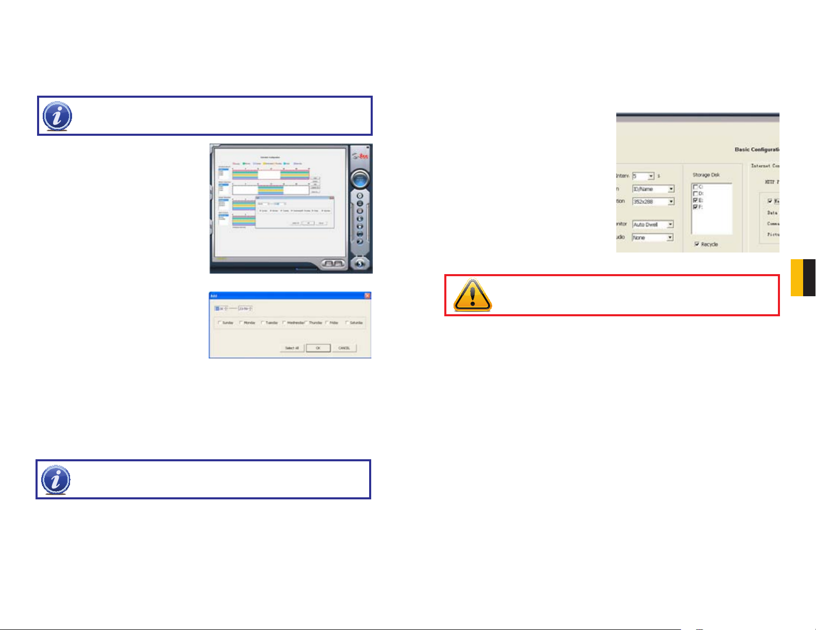
To create a new schedule;
STEP 1. Select the camera name in one
of the three record mode groups.
STEP 2. Click on Add.
6.3 RECORDING TO HARD DRIVE
Users can determine where recorded files will be saved on their hard drive(s). In addition,
the recorder can save to a series of drives or partitions by automatically jumping to the next
partition when the current one is full. If all the partitions are full and Recycling Record mode
has been enabled prior to recording by checking the box below the Storage Disk list, the new
data will overwrite the oldest recorded data automatically.
The destination drive(s) for recordings which also applies to images captured using
the Snapshot button - is set in the Basic
Configuration window. You can also set
a HDD minimum storage alarm which will
cause the system to alert you once the that
threshold has been reached. If the present
storage space is less than the minimum
storage needed and Recycling Recordings is
not selected, the recording will automatically
stop.
PICTURE 6-6
STEP 3. This will open a new window.
Set the start time and end time along
with the day(s) to which you wish the
schedule to apply.
STEP 4. Click OK to exit the Add
window.
Your new schedule will appear as a series of colored bars corresponding to the day(s) and
time(s) you’ve selected.
To edit a schedule, select a block of time and click Edit. You will be able to adjust the
schedule for that day and any other day in the same manner you used to create the schedule
in the Add window.
NOTE! When adding a new schedule, it should not duplicate an existing
schedule as this may cause a system error.
To add another block of time, such as an evening recording schedule to go with an early
morning schedule, you will need to repeat the process.
Clicking on Delete will remove a specific block of time from a specific day’s schedule.
Copy To allows you to apply the settings for one camera to another camera as well.
PICTURE 6-7
PICTURE 6-8
WARNING! You should have your files record to a disk or partition OTHER
than your “C” drive. This will avoid issues with the Recycling function.
CHAPTER 6 RECORDING, PLAYBACK AND RECORD SEARCH
30 31
Page 17
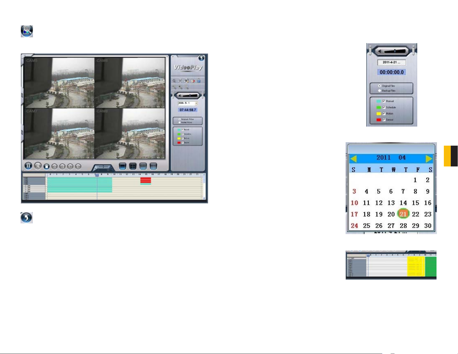
6.4 RECORD SEARCH AND PLAYBACK
Clicking the Search icon in the lower right of the Main Display Interface will cause it to
switch to the Search and Playback Interface. This interface handles both the Record
Search and Playback functions in addition to allowing you to back up your records.
RECORD SEARCH
Searches are based on date and time. Additional criteria can be selected to narrow the
search. These criteria include the type of the recording and where the files are saved.
STEP 1. Select whether the program
should search in the normal
destination location (See Section
6.3 Recording to Hard Drive)
and/or where you’ve backed up
recorded files (Covered in Section
6.5 Other functions)
STEP 2. Select the nature of the
recording - whether it was a
scheduled record, recorded as a
result of motion detection or etc. You
can select more than one category.
PICTURE 6-10
CHAPTER 6 RECORDING, PLAYBACK AND RECORD SEARCH
STEP 3. Enter the date and time. A
calendar will pop up. If there was an
event recorded on that date it will be
highlighted.
PICTURE 6-9
Pressing the back arrow in the upper right of the display will return you to live
surveillance in the Main Display Interface.
PICTURE 6-11
STEP 4. The program will display the
search results at the bottom of the
screen. They will be color coded to
indicate the mode in which they were
recorded.
PICTURE 6-12
32 33
Page 18

PLAYBACK
Once you have completed your search, you are ready to play back your files. The controls on
the Search and Playback Interface operate like any other video playback software.
Button Function Note
In addition, you can advance the playback to a certain point in the record by clicking on, and
sliding the progress indicator.
Play / Pause
Stop
Reverse
Previous Section
Next Section
Previous Frame.
Next Frame.
By default, the system will begin playing back the recording from Channel 1 when the Play
button is pressed.
Selecting a Screen Display Mode button
above the file list will open a pop-up window
allowing you to select which channel(s) to
play back. Only the screen display mode
buttons appropriate to your card will be
offered as options. Buttons allowing you to
select specific groups of channels will appear
depending on your card’s capabilities. Click
OK to return to the Playback window.
During playback, you can adjust the speed
of the recording with the slider located at the
bottom of the interface.
Only functional when playing back in single channel mode.
Only functional when playing back in single channel and in
Pause mode.
PICTURE 6-13
PICTURE 6-14
PICTURE 6-15
At the top of the file visualizer, the bar represents the time when the file was recorded. Clicking
on this will magnify it to show minutes allowing a more precise search.
NOTE! Clicking on any channel in multi-screen playback will switch the display
to a single-channel view of that feed. Click again to return to the previous
playback mode.
6.5 OTHER FUNCTIONS
Other functions within this interface allow you to back up files, capture still images, print
images and digitally zoom in on a recording.
FILE BACKUP
Clicking on the file icon allows you to back up your files to another drive for use
elsewhere or simply to preserve them without having to worry about them being
overwritten by the Recycling Record function.
The Backup window operates much like the
Record Search window and it is divided into
four main areas:
A: Camera Selection Area - Select which
cameras’ recordings you wish to back up.
B: Time and Date Selection Area - Select
the start and end dates and times for the
records you wish to back up.
C: Operation Area - Select the save path
for the backup files. You can also choose to
save a standalone playback program to allow
others to view the files.
D: Information Area - The program will use
this area for any warnings or notices.
Click Start to begin backing up your files.
PICTURE 6-16
CHAPTER 6 RECORDING, PLAYBACK AND RECORD SEARCH
34 35
Page 19

DELETING RECORDED FILES
While older files will get overwritten by the Recycling Recording function as the hard drive
fills up, you can delete unnecessary or unwanted recordings before then.
This function will delete a file or blocks of
files from a specific camera or which were
recorded during a set time.
Select the channel on the left side, and then
the select start date and time and end date
and time of the files you wish to delete.
Click Start to delete files.
You can also remove files manually by
deleting them from the folder where they are
stored, just as with any other PC file.
PICTURE 6-17
CAPTURE PICTURES
This feature allows you to capture still images from a recorded event so they can be saved or
printed out.
When the Search and Playback Interface is displaying only a single channel and the user
hits the Play/Pause button a second time to pause playback, then the video is in Playback
Pause mode.
At this time the function buttons above the
File Search panel will be enabled.
Pressing the Snapshot button will bring up the Snap window.
PICTURE 6-20
Select the number of sequential images you wish to capture and set the save path. The save
path can also be set in the Basic Configuration menu in the Capture Browse setting. You
can also chose to include which camera took the video and/or the date and time that it was
recorded within the image itself.
Once you have made your selections, pressing the Snap button will save the images. Press
Save to preserve your settings for future use or Exit, if you do not wish to retain the settings.
CHAPTER 6 RECORDING, PLAYBACK AND RECORD SEARCH
PICTURE 6-18
Snapshot Print setup Print picture
NOTE! This feature is only available in Playback Pause mode on a single
channel.
In addition, a second menu will appear below the Search panel. This allows you to make
picture quality adjustments for the present channel, including brightness, contrast, saturation
and hue.
These changes will not affect the actual
recorded image. Pressing the Default icon
in the lower right of the panel will restore the
original settings.
Make the desired adjustments to the image
and then select the Snapshot icon.
PICTURE 6-19
The Print Setup button will bring up a
conventional Print Setup window to allow you
to make settings as normal.
Clicking the Print button will open a Print
Preview dialog that includes some extra
features.
Select the Position radio button and adjust
the position of the image on the page using
the + and - buttons.
Selecting the Size radio button will allow you
to adjust the image size using those same +
and - buttons.
PICTURE 6-21
36 37
Page 20

DIGITAL IMAGE ZOOM
During multi-screen playback, clicking on one channel will cause the display to shift to a single
channel display mode.
While in single channel playback mode the
digital zoom controls are enabled. These
allow you to zoom in or out of an area of the
recording.
Zoom In
Zoom Out
Revert to original size
PICTURE 6-22
SYSTEM SETTINGS
Beyond the recording settings, there are other features of this video capture card which need
to be enabled or configured.
The Settings window is entered by clicking on the wrench icon on the left of the Main Display
Interface.
CHAPTER 7
CHAPTER 7 SYSTEM SETTINGS
PICTURE 7-1
Basic Configuration Schedule configuration
Video configuration Motion Detection Configuration
Alarm Configuration P.T.Z Configuration
User Configuration Save and Return
38 39
Page 21

7.1 BASIC CONFIGURATION
Your card is pre-configured with default settings which meet the needs of most users,
however it is designed to allow you maximum flexibility in configuring the system to meet your
specific needs.
In the upper portion of the Basic Configuration window are settings which control additional
aspects of your cameras. We have already covered the recording-specific settings in the
previous chapter.
CAMERA DISPLAY SETTINGS
Dwell Interval
If you have enabled Auto Dwell function on the main interface page, then you can set the
dwell time, in seconds, of a screen here.
Caption
There are four options, None, ID, Name,
and ID/Name for users to select for all the
channels.
‘None’ means no title or name;
‘ID’ means camera numbers, i.e. 1, 2, 3
and so on;
‘Name’ means camera names, i.e.
Cam1, Cam2 and so on;
‘ID/Name’ means both camera number
and camera name, i.e. 1/Cam1, 2/
Cam2 and so on.
Resolution
You may have resolution options of 320×240, 640x480, or 704x480 (NTSC) for users to select
for all the channels depending on the card you are using.
Call Monitor
You can connect another monitor to the Spot Out port on the card and select the display
modes here.
PICTURE 7-2
SYSTEM LOG IN AND REBOOT
You can enter your User Name and Password that you use to log into Windows so that the
SuperDVR can log in upon startup or reboot.
Since the windows system may become
unstable after a couple of days of continuous
operating, it may cause SuperDVR to
become unstable. You can use the software
support auto-reboot option to help avoid this.
Select the PC Auto Reboot tab in the center
of the Basic Configuration screen and then
check the box next to PC Auto Reboot and
set the interval by day, which will cause the
system to reboot automatically according to
your schedule.
PICTURE 7-3
VIDEO CONFIGURATION
Clicking on the video configuration icon will open a new page which will allow you to
change the contrast, brightness, hue, saturation and auto gain of individual cameras, by
moving the levers on the bars. Clicking Default will restore the default values.
The range of values is from 0 to 255.
Contrast - Set image color contrast.
Brightness - Set image brightness.
Hue - Set image hue.
Saturation - Set image Saturation
PICTURE 7-4
CHAPTER 7 SYSTEM SETTINGS
40 41
Page 22

7.2 ALARM CONFIGURATION
The system can receive alarm signals generated both by attached devices as well as
from those from over a network. Alarms can also be generated when motion is detected.
TRIGGERED ACTIONS
Each type of alarm can be configured to generate an audible alarm - externally or internally, as
well as triggering other, pre-defined actions.
PICTURE 7-7
Buzzer - Select whether to activate the computer buzzer if alarms have been triggered and
also select how long the buzzer sounds.
Pre-Alarm Record - Select whether the system will pre-record and for how long.
Big Screen Holding Time - The corresponding channel will be full screen when an alarm is
triggered. Set the full screen hold time here.
Motion Holding Time - How long the recording continues after motion stops.
Sensor Holding Time - How long the recording continues after sensor stops.
Disk Shortage Alarm - If the Partition free space is less than the set percent, the system will
stop recording or recycling, but will sound an alert according to the settings.
Alarm Record
Every sensor can trigger multiple channels to record. For example: if CAM1, CAM4 and CAM5
are selected for Sensor2, then once the sensor is activated, CAM1, CAM4 and CAM5 will
begin to record.
CHAPTER 7 SYSTEM SETTINGS
PICTURE 7-5
ALARM TYPES
Different conditions can be set to trigger an alarm.
Video Loss - Users can select alarm output
for this option.
For example: If you select alarm_out1 and
alarm_out3 for video loss. Then video loss of
any channel will trigger alarm_out1, alarm_
out3 to show a red light in the Alarm output
status panel
Disk Alarm - When HDD available space is
less than the set value, it will trigger alarm.
Sensor - If users have mounted sensors,
when the sensors have been activated, it will
trigger the selected output alarms.
Motion - Users can set the output of motion
detection alarm by different alarms and
remote alarm.
Users can also select the voltage (high or low) for alarm signals.
PICTURE 7-6
42 43
Page 23

Receiver's E-mail Address
Sender's SMTP
Sender's E-mail Address
Sender's User Name
Sender's Password
E-mail Subject
Auto Mail
Any of the alarm types can be configured to generate an alert e-mail but it is especially useful
when triggered by a motion detection event.
NOTE! Before configuring the Auto Mail function, be sure to set up Motion
Detection.
Click the Auto Mail icon on the left top side of alarm configuration page to enter the Auto
Mail Setup Interface.
PICTURE 7-8
Users can set receiving and sending E-mail
SMTP server and address. The address
of receiver and sender can be the same.
However, this is not recommended as it can
overflow your e-mail account. Some free
e-mail providers also place a daily limit on
the number of e-mails sent and received by a
single account.
PICTURE 7-9
To test the settings, click Send Mail Test.
If all settings are okay, response ‘Message
Sent Successfully’ will pop up. If some
settings are wrong, a warning message will
pop up.
If Attachment is enabled,then a picture of
what triggered the alarm will be sent to the
selected mailbox.
PICTURE 7-10
NOTE! Only one picture will be attached for each alarm event.
7.3 E-MAP CONFIGURATION
E-map is used to show full geographic range covered by the whole monitoring system in the
form of map. An E-map features simple operation and direct display of status.
NOTE! The system only supports bmp or jpg image format for E-Map files.
You will need to draw the floor plan of where
you want to install the cameras in a program
such as Paint or Photoshop and save it in
BMP or JPG format before using this feature.
Files will be proportionally scaled to 833x678
pixels when in use.
Click on Emap Edit and then right-click in
the demonstration map currently displayed.
Select Load Picture in the pop-up. Navigate
to where the image is stored on your
computer and open the file. The map will be
displayed in this interface, allowing you to
add the cameras to the map.
Drag the icon of a camera to the
corresponding position on the map, a
maximum of 32 cameras can be set
simultaneously, Click Change icon of camera
by right key to change icon or click Delete to
cancel a camera. After editing, right-click in
the map display area and select Save Map in
the pop-up to save the current map.
PICTURE 7-11
PICTURE 7-12
CHAPTER 7 SYSTEM SETTINGS
44 45
Page 24

A gray map icon can be drawn to the corresponding position in the map on the right and set it
as a sub-map of the current map, or click the gray map icon on the left by right key and select
‘Open’ to build a new map. You can also click the blue map icon on the left by right key, and
select ‘Rename’ to change the name of the map or select ‘Close’ to cancel this map. The map
tree can only support three levels of maps and submaps.
USING THE E-MAP
To view the E-map during monitoring, click on its icon on the right side of the Main
Display Interface.
When a channel alarm is triggered, the camera icon will flash a yellow alarm signal. Select
‘Auto Show’, in case of an accidental alarm, an alarming screen will pop out automatically and
you can know about the alarming position immediately. Right-click on the camera to bring up
its feed immediately.
Alternately, you can enable Auto Show to bring up the E-map when you’re in another viewing
mode.
7.4 USER CONFIGURATION
User accounts, privileges and passwords can be added, changed or deleted in this
menu. After installing the SuperDVR program, it will automatically create an administrator
account with the user name SYSTEM with no password. Users can use this name to log in the
system and Add, Edit or Delete users’ parameters.
PICTURE 7-13
USER RIGHTS
Select a user in the User Configuration area, and
click Edit to enter the Edit User area
Users can edit user’s password and rights here, but
not the user name.
CHAPTER 7 SYSTEM SETTINGS
The system offers three kinds of rights:
Administrator: this user has the right to change all
the settings and playback. This user also has the
right to assign users power user rights and normal
user rights.
Power User: This type of user is authorized by the
administrator. The administrator assigns rights to
power users by checking boxes in the Power User
list.
Normal User: Normal user’s rights are also
assigned by the administrator. They have the same
list of available rights as Power Users. However,
whether they can possess a right is be decided by
the administrator. Only if the administrator assigns
that right, will they have the right. For example, if
Basic Configuration is checked, the Normal User
can access these functions.
NOTE! Administrators can change and authorize rights to Power Users and
Normal Users, but they cannot change or authorize other Administrators’
rights.
PICTURE 7-14
PICTURE 7-15
46 47
Page 25

ADD USER
Click Add in User Configuration to access
the Add User area.
Enter the user name, password, confirm
password and select user rights, and then
click OK.
Delete User
Select the user name in User
Configuration, and click Delete, and
confirm delete.
PICTURE 7-16
PICTURE 7-17
P.T.Z. CAMERAS
If you are installing a PTZ camera, then the PTZ controls must be set up before operating the
camera. You should have your PTZ camera’s manual handy when configuring and operating
the PTZ camera for the first time. You should have the information regarding the Baud Rate,
Protocol and Address ready before you begin.
CHAPTER 8
8.1 P.T.Z CONTROL CONFIGURATION
The PTZ settings are found in the Configuration menu. Click on the wrench icon on the
right side of the Display Interface to enter the Configuration menu and then click on the
PTZ menu to configure its settings.
CHAPTER 8 P.T.Z. CAMERAS
PICTURE 8-1
PROTOCOL SETUP
You can select different protocols, serial port
number for P.T.Z devices.
The settings you enter here must match the
setting on the PTZ camera.
Port - Users can set serial port number.
Protocol - Communication protocol of the
P.T.Z device.
SuperDVR supports the following protocols:
DSCP, DH-SD, Lilian, Minking, Neon, PelcoD,
PelcoP, Star, VIDO, VISCA
Address - Communication address of P.T.Z
device (ID number)
PICTURE 8-2
48 49
Page 26

SERIAL PORTS SETUP
Users should first enable the P.T.Z control function of a camera and then select a port number
in P.T.Z Protocol Setup. The values entered for each parameter should match those on the
camera itself.
- Set the port number.
Port
Baud Rate - Set P.T.Z device Baud Rate to
match setting on camera. The default
value is 9600.
Data Bits - Default value is 8.
Parity - Odd and even parity bit, default
None.
Stop Bits - The Default value is 1.
PICTURE 8-3
8.2 PTZ OPERATION
The PTZ Controls can be accessed directly from the Main Display Interface by clicking
on the PTZ Control icon on the right side of the display. This will replace the buttons and
functions on the right side of the display with the PTZ controls.
Clicking on Set PTZ speed allows you to
adjust the Pan Speeds, Tilt Speeds, Focus
Speeds and Zoom Speeds for all connected
PTZ cameras.
Pan Speed - Set horizontal rotating speed.
Tilt Speed - Set vertical rotating speed.
Focus Speed - Set camera focus speed.
Zoom Speed - Set zoom in/ zoom out
speed.
Click
appear; users can choose different presets or
group sets.
and a pop-up window will
PICTURE 8-6
PICTURE 8-7
PRESET AND GROUP SELECT
Click to set Preset point and
change Preset point name. Every Group
includes multiple Preset points. If users
select preset1, preset2 and preset3 for
group1, preset1, preset2 and preset3 will be
automatically accessed in sequence after
users select group1 for auto scout.
PICTURE 8-4
You can control P.T.Z. devices by clicking on
its display. The selected camera channel will
be highlighted in red indicating that it is ready
to be controlled.
Focus, Zoom and Iris (light level) are adjusted
by the use of the + and - keys to either side.
A PTZ function (direction, zoom, etc.) will
continue as long as the user is holding down
the left mouse button while the cursor is over
the button or until it reaches a physical limit.
Preset
Click , and a pop-up will
appear allowing you to configure settings for
a Preset.
Dwell- Set the dwell time for a Preset. The
camera will wait this long before moving on to
the next action.
PICTURE 8-5
PICTURE 8-8
PICTURE 8-9
50 51
CHAPTER 8 P.T.Z. CAMERAS
Page 27

REMOTE SURVEILLANCE
Shut Down
Devices and Printers
Help and Support
CHAPTER 9
& PLAYBACK
9.1 REMOTE LIVE SURVEILLANCE
Surveillance system supports Remote Surveillance through LAN, Internet, and Intranet. Simply
enable the Webcam function of the system on a computer which is connected to the Internet,
and the computer system will become an Internet Webcam server. On any other computer
that connects to Internet, enter the public IP server address in an Internet Explorer browser
window. Remote users can get high quality real-time image from the server (depending on
available bandwidth) and also control the P.T.Z devices.
REMOTE SURVEILLANCE SERVER CONFIGURATION
Users should first enable the Web Camera Services in Basic Configuration and set other
settings as shown below:
HTTP Port - Web service & download
service port, default value is 80.
Data Port - Data transmission port, default
value is 1159.
Command Port - Control command port,
default value is 1160.
Picture Quality - Default value is medium.
PICTURE 9-1
9.2 CONFIGURING ROUTER FOR REMOTE ACCESS
PART 1: FIND OUT THE IP ADDRESS OF THE SYSTEM
STEP 1. To access the router’s settings you will need to enter the Command (CMD)
panel on the computer containing your video capture card.
A. WINDOWS XP – Select Run from
your Windows START menu (lower
left of screen) and type “cmd” after
the prompt.
B. WINDOWS VISTA and WINDOWS
7 – Click on the START menu
(Windows icon) in the lower left of
your screen. Type “cmd” into the field
that says, “Search programs and
files” and hit ENTER or click on the
magnifying glass icon.
Microso Internet Explorer
Microso Office Outlook 2007
iTunes
Adobe Acrobat
All Programs
start
start
Inbox Microsof... iTunes
PICTURE 9-2
Microso Office Outlook 2007
Scky Notes
iTunes
Adobe Acrobat
All Programs
cmd
Devices and Printers
Default Programs
Help and Support
Run
Log Off
Default Programs
Shut down
If your internet connection does not have enough bandwidth available you can use the Picture
Quality option to send the video over the internet at a lower quality setting then you are using
for recording. That way you will be able to see the images over the internet at lower quality
PICTURE 9-3
while still recording at the higher quality setting.
STEP 2. Type “ipconfig” at the prompt
NOTE! The minimum speed on the internet connection is 1Mbps download
and 1Mbps upload for 4 and 8 channels, and 2Mbps download and upload
(Red arrow in Picture 9-4) to
access router settings.
for 16 channels. You can check the speed of your connection at both ends by
going www.SpeedTest.net from both the computer in which the card is installed as well as
the remote computer which you will be using.
STEP 3. Write down the IP4v address
(Blue arrow) as well as the Gateway
and Subnet Mask numbers (Green
arrows). The IP4v address is the
address used by the card.
PICTURE 9-4
52 53
CHAPTER 9
REMOTE SURVEILLANCE & PLAYBACK
Page 28

PART 2: DETERMINE THE NUMBER OF ROUTERS ON THE NETWORK
To find out the number of routers on your network, you will need to download a FREE router
detection program.
STEP 1. Go to
http://www.pcwintech.com/shanes-toolbox
STEP 2. Click on Detect Multiple
Routers to begin the download.
STEP 6. If there is only one router detected, then you may skip to Part 3: Simple Port
Forwarding.
If Multiple Routers are Detected
If there are multiple routers, you will see a
display similar to Picture 9-8.
If so, it may be preferable to connect your
DVR and computer to the router that
connects directly to the Internet. However, this
is not always possible depending upon your
particular situation.
STEP 3. Unzip the application to install it.
STEP 4. Click on the detect_routers
application to run it.
STEP 5. Click on CHECK NOW to
detect how many Routers are in the
network.
PICTURE 9-5
PICTURE 9-6
PICTURE 9-8
In this case, you will need to proceed with the next section using the IP address for Router 1
to forward its ports. After that, you will need to proceed to Part 4.
CHAPTER 9
REMOTE SURVEILLANCE & PLAYBACK
PICTURE 9-7
54 55
Page 29

PART 3: SIMPLE PORT FORWARDING
Download the FREE Simple Port Forwarding program from:
http://www.simpleportforwarding.com/download
STEP 1. Click on Download in any of the mirrors or the Direct Download link to download
and install this program.
PICTURE 9-9
STEP 2. Once the program is installed,
go to the Windows Start Menu
(Windows icon in the lower left of
your monitor) and look for Simple
Port Forwarding in the program list.
Click on the program to launch it.
PICTURE 9-10
STEP 3. Once Simple Port Forwarding has launched, select your router from the list.
The default Router IP and Login information will automatically come up. If you have
previously changed the login information, then you will have to enter it manually
STEP 5. Click on ADD CUSTOM.
STEP 6. Input the required information:
Name: (You can name your DVR if you
wish)
Type: TCP
Start Port: 80
End Port:80
IP add: IP of DVR obtained in
Part 1.
Click on ADD
Repeat for port 1159 and 1160.
PICTURE 9-12
CHAPTER 9
PICTURE 9-13
REMOTE SURVEILLANCE & PLAYBACK
PICTURE 9-11
STEP 4. Click on “+” at the bottom to open the window allowing you to set your ports.
56 57
Page 30

STEP 7. You will now be returned to the main window of the program. The ports you
added will now show on the list. Click on Update Router at the bottom.
If for some reason, a port or ports that you forwarded are not listed in the Router and if you
see a message in the Scripts list on the left side of the window stating that the port already
exists (Red box in Picture 9-16), then you will need to change the Port 80 to 85 in the DVR
and start over again.
PICTURE 9-16
PICTURE 9-14
STEP 8. You will see the “Updating is in progress” message. Please wait until you see it
say DONE at the bottom.
PICTURE 9-15
STEP 9. Once you receive the DONE message that the ports have been successfully
forwarded, test if the ports are working by clicking on item number 7 in the Check
List - Test that the ports now work.
CHAPTER 9
REMOTE SURVEILLANCE & PLAYBACK
PICTURE 9-17
58 59
Page 31

STEP 10. Click on Begin.
If you receive a message stating that the port is online and can be reached, then you have
set it up correctly.
PICTURE 9-18
To connect to your DVR from the Internet, you will need to put the Internet IP address shown
after “Your Internet Address:” message into your Internet Explorer browser or access pro-
gram window.
NOTE! The default value is 80. If port 80 is already occupied by another device
on the network, then another port will need to be selected. Choose another
number in the same range; 81-89. In this case, you will have to add the port to
the IP address when entering it into the Internet Explorer window. For example,
if the port is now 82, then you will need to enter http://192.168.0.25:82
PART 4: SETTING UP DMZ IN ROUTER 2
NOTE! You will only need to proceed with this section if you detected a
second router in Section 2.
STEP 1. Login into Router 1 by putting
the IP of Router 1 into the Internet
Explorer browser, as in the example
shown in Picture 9-19 where the IP
address of Router 1 is 192.168.0.1
STEP 2. Find the status page on the
router settings that shows the WAN/
Internet IP address and write it down
this WAN IP address.
STEP 3. Log into the Router 2 by putting
the IP of Router 2 into the Internet
Explorer browser, as in example
shown in Picture 9-19 where the IP
address of Router 2 is 192.168.1.1
STEP 4. Find the DMZ page in the router
settings.
STEP 5. Enter the WAN IP for Router 1
into the DMZ page and enable DMZ.
NOTE! If you do not have a DMZ setting in the router, check to see if there
is a Bridge setting. If so, then use the Bridge setting instead of DMZ.
STEP 6. Save your changes.
You have forwarded the ports on the router to which the DVR is connected, to the IP address
of the DVR, and set the primary router to pass the connection to this router.
PICTURE 9-19
CHAPTER 9
REMOTE SURVEILLANCE & PLAYBACK
IMPORTANT! Do not use 255 or higher to complete your IP address as these
addresses are reserved for other devices and components.
60 61
Page 32

9.3 DDNS (DYNAMIC DOMAIN NAME SERVICE)
You can access the system over the Internet using a static or dynamic IP address. However,
your service provider can change this dynamic address from time to time. When it changes,
you will have to return to www.MyIPAaddress.com to get the new public IP address.
There are two solutions to this problem. The first would be to obtain a static IP address from
your ISP – which can be expensive. A second – and free – option is to use a dynamic domain
name service (DDNS) to get a domain name that can be linked to your dynamic IP address. In
addition to automatically keeping up with the changes in the address, you will now be able to
enter a domain name rather than a string of digits when accessing the DVR in Internet Explorer.
We recommend using www.MyQ-See.com or www.DynDNS.com as the DVR has been
already configured to accept account information from these two services.
NOTE! Before setting up DDNS, you must have previously set up Port
Forwarding as described in the previous section.
9.4 ACCESSING THE DVR USING INTERNET EXPLORER
Once you have configured the network settings on the DVR to match those on your router
and forwarded the ports needed by the DVR to enable remote access over the Internet, you
will be ready to remotely view your cameras using a webcam program based on an ActiveX
control. For this to work, you will have to enable the ActiveX control options that are built into
Internet Explorer. It is strongly suggested that you be running the latest version of Internet
Explorer (currently IE8). The instructions below will describe the process using that version of
the browser. Instructions for users with IE6 or 7 are available in the Resources library of our
Technical Support page.
USER ACCOUNT CONTROL FOR WINDOWS VISTA AND WINDOWS 7
Some users of computers using Windows Vista or Windows 7 operating systems may receive
an error message informing of a codec that is missing or not installed. This conflict can be
resolved by turning off User Account Control (UAC).
SETTING UP DDNS
The following instructions are for setting up DDNS with MyQ-See, instructions for DynDNS are
available on their website.
STEP 1. Using a computer that is
connected to the same router as the
DVR, use Internet Explorer to go to
www.MyQ-See.com
STEP 2. Fill out the required information
to register and click the Submit
button at the bottom of the screen.
STEP 3. The next page will ask you
to create a domain name. Domain
names must begin with a letter (a-z)
or a number (0-9) and cannot contain
a hyphen. Once you’ve decided
upon a name, click on the “Request
Domain” button. If it is available you
will see a confirmation screen along
with the IP address associated with it.
Confirm that this matches the number
obtained in Network Settings. Your
domain name will look like this:
http://example.myq-see.com
STEP 4. Once you have obtained your
domain name, you will need to
configure the DVR for access using it.
STEP 5. Once you have completed steps 1-4, click on the link on the MyQ-See website
to download the MyQ-See software program onto your computer and install it so that
it can monitor the IP address assigned to your account. The computer must always be
on in order to update the link to the public IP address when it changes.
PICTURE 9-20
PICTURE 9-21
Windows Vista
STEP 1. Open the Control Panel
(accessible by clicking on the
Windows icon in the lower left of your
screen.
PICTURE 9-23
STEP 2. Select User Accounts and
Family Safety.
PICTURE 9-24
STEP 3. Select “Add or Remove User
Account.”
PICTURE 9-25
STEP 4. Select the desired user account.
PICTURE 9-26
62 63
CHAPTER 9
REMOTE SURVEILLANCE & PLAYBACK
Page 33

STEP 5. Select Turn User Account
Control on or off
Setting Up ActiveX Control
STEP 1. Open Internet Explorer
STEP 2. Click on Tools
STEP 3. Select Internet Options in the
pull-down menu
PICTURE 9-27
STEP 6. Uncheck the box next to “Use
User Account Control (UAC) to help
protect your computer.”
STEP 7. You will then be asked to restart
your computer for the change to take
effect.
Windows 7
STEP 1. Open up the Start Menu
(accessible by clicking on the
Windows icon in the lower left of your
screen.
STEP 2. Type “uac” into the search bar
and hit ENTER. The User Account
Control will open or you will be offered
a link to click to open it.
PICTURE 9-28
Microso Office Outlook 2007
Scky Notes
iTunes
Adobe Acrobat
All Programs
uac
PICTURE 9-29
Devices and Printers
Default Programs
Help and Support
Shut down
STEP 4. Click on the Security Tab
STEP 5. Select Trusted Sites
STEP 6. Click on the Sites button
STEP 7. Uncheck the “Require server
verification (https:) for all sites in
this zone” button.
STEP 8. Type the DVR’s IP address
(obtained during Network Setup)
or DDNS domain name into the “Add
this website to the zone:” box.
STEP 9. Click the Add button
STEP 10. Close the window.
PICTURE 9-32
PICTURE 9-33
CHAPTER 9
REMOTE SURVEILLANCE & PLAYBACK
PICTURE 9-34
STEP 3. Move slider to lowest setting
and press OK.
PICTURE 9-31
64 65
Page 34

STEP 11. Click the Custom level…
button.
STEP 12. Pull down the “Reset to:”
menu button and select Low
PICTURE 9-35
STEP 13. Click the Reset button
STEP 14. Click “Yes” when asked, “Are
you sure you want to change the
setting for this zone?”
STEP 15. Click OK
STEP 16. Click Apply
STEP 17. Click OK
STEP 18. Close Internet Explorer
You are now ready to access the DVR using Internet Explorer.
Open a browser window in Internet Explorer
and enter the IP address or DDNS name
(obtained in Section 9.3 DDNS (Dynamic
Domain Name Service)) into the address
bar.
You will see a log in screen similar to that
shown in Picture 9-38 or yellow alert bar at
the top of the window asking for permission
to open an ActiveX application. Allow it to
install webrec.cab control to reach the
sign-in screen.
Instructions for controlling your system
remotely are in the next section.
PICTURE 9-37
PICTURE 9-38
CHAPTER 9
REMOTE SURVEILLANCE & PLAYBACK
PICTURE 9-36
66 67
Page 35

ACCESSING THE INTERNET EXPLORER CLIENT
After enabling network server on the unit, and enabling ActiveX, users can view the video
from the cameras over the LAN or Internet through Internet Explorer. This unit only supports
Internet Explorer browser, no other browsers are supported. It also supports Win2000, WinXP,
Vista, and Win7.
Input the IP address of the computer with the card if accessing from LAN, or the public IP
address of the router if accessing from the internet, into the Internet Explorer window to reach
the window that prompts you to install the ActiveX control.
Icon Description
Controls for PTZ Cameras: Move Up. Move Down.
Move Left rotate left. Move Right. Stop Rotating.
PTZ ‘Focus’ buttons. Far Focus Near Focus
PTZ ‘Zoom’ buttons. Zoom In Zoom Out
You will get a message asking you to install
the file NetVideo.cab. Install it as normal.
You will then be asked to log in. Use the
same User Name and Password as you
would when logging in from the computer
itself. The default User Name is SYSTEM
without a password.
Once you have entered the User Name and
Password, click OK to log in.
As you can see, the
WebCam main interface
is very similar to the
SuperDVR main interface.
PICTURE 9-39
PICTURE 9-40
PTZ ‘Iris’ button. Increase light. Decrease light
Go to a Preset Point
Set a Preset Point
Speed dome. Adjust PTZ speed.
Single channel with full screen display
Four channel mode - four cameras displayed
Contrast adjustment
Brightness adjustment
Hue adjustment
Saturation adjustment
Log in/ Log out
Record playback
System Configuration
LAN or Master stream is for users on the same network as
your system. It has higher frame rate and needs higher network
bandwidth
Internet, or sub stream, has a lower frame rate and requires
lower network bandwidth. Users can select the stream
according to their bandwidth.
CHAPTER 9
REMOTE SURVEILLANCE & PLAYBACK
PICTURE 9-41
68 69
Page 36

Right-clicking the mouse in the main interface
will open a sub menu.
9.5 REMOTE PLAYBACK
RECORD PLAYBACK AND CONTROL
Open Stream - Click this item, selected
channel will open
Close Stream - Click this item, selected
channel will close
Close All - Click this item, all channels will
close
Full Screen - Select this item, the picture
will display full screen. Double click or
click right mouse to return to the previous
interface.
PICTURE 9-42
Click
interface, and the remote playback interface
will appear:
button on the Webcam main
Play/ Pause
Stop
Adjust the speed of playing back. Users can adjust play speed as needed.
Playing back backup. Users can click Backup to enter into the Remote
Backup interface:
REMOTE BACKUP
STEP 1. Select the date, channel, then
click Search button. It will list all files
recorded for the day.
STEP 2. Click Browse button, set the
saving path.
STEP 3. Select files in the search area.
Users can hold shift button on the
keyboard and select multi files with
mouse simultaneously.
STEP 4. Click Backup button to do
remote backup.
PICTURE 9-43
CHAPTER 9
REMOTE SURVEILLANCE & PLAYBACK
PICTURE 9-44
The backup files will be saved in AVI format. Most computer users can play with most third
party players directly.
If you do not have a media player installed, we suggest using Windows Media Player Classic
which is available as a free download from many web sites and is easily found via an online
search.
70 71
Page 37

Right-clicking the mouse in the search area
will open a sub menu.
PICTURE 9-45
If you want to view all channels, click Select all, then all check boxes before channels will be
selected.
Click Clear all to clear all selected channels; if users select a certain channel, click Select this
channel, then just this channel be selected.
Click Clear this channel to deselect that channel.
Return to previous main interface
Multiple Channels playback control
The system default playback modes
are single and four channel. If you need
to change to other channels, then click
the single channel button to bring up the
1-channel configuration window where you
can select one channel from all the available
channels for playing back.
The four channel configuration window
will display when the four channel icon
is selected allowing you to select any four
channels from all the available channels for
play back.
PICTURE 9-46
The ruler on top of the bar shows the hours of the day. Right-click the ruler, it will be magnified
10 times allowing users to see the time marks more clearly.
When searching for a certain section of a record, draw the bar to the desired position. If
necessary, right-click the bar to see the magnified time marks for precise search.
You can click the Play button to play the selected record, Then return to live display mode after
finishing remote playback, it will display a message ‘Connecting…’on the screen. And you
may click “Large Picture” or “Quad Picture” button to refresh the screen to get live picture.
CHAPTER 9
PICTURE 9-47
Data preview shows the recorded data for different channels during corresponding time, the
left side shows the available channels. When a certain channel has been selected for playing
back, the background color will be highlighted, or its dark gray and a tick sign will appear
beside the channel title.
PICTURE 9-48
The data preview area at the center gives details of the recorded files. Different colors of the
bar show different types of records.
BLUE Manually Recorded
YELLOW
Motion Detection RED Sensor Alarm
GREEN
Schedule Recorded
72 73
REMOTE SURVEILLANCE & PLAYBACK
Page 38

9.6 SYSTEM SETUP
Click and enter the main setup interface.
PICTURE 9-49
Server PC Setup
You can enter the user name and password
for the computer which houses the video
capture card in the appropriate boxes. This
way, when the computer system restarts, it
will access to the system with the user name
and password input in these boxes to begin
running the SuperDVR application.
As the Windows system may become unstable after a couple of days of continuous operation.
It may cause the SuperDVR system to become unstable. The software supports auto-reboot.
Select PC Autoreboot and set the interval by day, which will instruct the system to reboot
automatically according to your settings.
PICTURE 9-51
ALARM SETUP
The Alarm setup configuration is similar to that in the SuperDVR software.
NOTE! When multiple clients access the system configuration interface
simultaneous, the user who enters into that interface first gets priority and
then others will not be able to access it.
BASIC CONFIGURATION
Caption
There are four options: None, ID, Name and
ID/Name to select from.
‘None’ means no title or name.
‘ID’ means camera numbers, i.e. 1,2,3 and so on.
‘Name’ means camera names,i.e. Cam1, Cam2 and so on.
‘ID/Name’ means both camera number and camera name,i.e. 1/Cam1, 2/Cam2 and so on.
Live audio
Your card supports accepts audio input through the RCA ports on the Audio In dongle. You
can choose the video channel to associate with these audio signals.
PICTURE 9-50
Buzzer - Users can select whether to sound
the computer buzzer if the alarms have
been triggered also select how long the
buzzer sounds.
Full screen alarm - Users can select
whether channel will be full screen when
alarm triggered. Set the full screen hold
time here
Pre-alarm record - Users can select whether to enable alarm pre-recording and also pre-
record time
Disk storage alarm - If the Partition’s free space is less than the assigned percentage, it will
stop recording or recycling, but give alarm tips according to the settings
Motion holding time - The continuous recording time after motion stopped
Sensor holding time - The continuous recording time after sensor stopped
PICTURE 9-52
CHAPTER 9
REMOTE SURVEILLANCE & PLAYBACK
74 75
Page 39

CAMERA SETUP
Click the camera icon and the Camera Setup configuration will appear
Title - Channel name. Users can set the
channel name from Cam1, Cam2, Cam3
and Cam4.
Camera security - Users are divided into
two standards: normal user and super
admin. By selecting this option, only
administrator can see corresponding
channels.
Time stamp - If selecting the check box, record time will be displayed on the screen when
playing back the record.
Net quality - There are five options to choose from: lowest, lower, medium, higher and
highest. The higher the picture quality is, the clearer the picture is, but the more bandwidth
it takes to transmit the files.
Audio in - If users select the check box, Webcam will record audio along with the video.
Otherwise, it will not record audio.
NOTE! The default setting is that Audio input1 matches channel1 and
Audio input2 matches channel2
By clicking Copy To you can copy the setting of this channel to any other selected channel.
PICTURE 9-53
ALARM CONFIGURATION
Click the alarm icon to open the Alarm Configuration window
You can set the alarm type: Motion and other.
There are two alarm out options to choose
from: Buzzer and Auto mail.
Buzzer - Enable buzzer on board for alarm
Auto mail - When alarm is triggered, the
system will send an e-mail to users
automatically.
By clicking Copy To you can copy the setting of this channel to any other selected channel.
PICTURE 9-55
RECORD CONFIGURATION
Click the Record icon to open the Record Configuration interface.
SCHEDULE CONFIGURATION
Click the Calendar icon to enter the Schedule Configuration page.
There are three kinds of recording modes:
manual record, schedule record, motion
detection/Sensor alarm record. Users can set
schedules from Sunday to Monday separately
for all of the three recording modes. Sensor
alarm recording mode has the highest priority
of the options.
When users need to edit the schedule for a
channel, select the camera name in the left
Camera group first.
PICTURE 9-54
Click icon and brush on the weekday schedule to add time; click icon and click on the
weekday schedule to delete time.
By clicking Copy To you can copy the setting of this channel to any other selected channel.
Record setup
There are three kinds of recording modes:
Manual record, Schedule record and Motion
record
You can use multiple cameras to record.
Every camera works separately and recorded
files are also saved separately.
Record quality - There are five quality options to select from: lowest, lower, medium, higher
and highest. The higher the record quality is, the clearer the recorded image is and the
more hard space the recording takes up.
Manual record - By selecting this option, the selected camera image will be recorded and
saved all the time.
Schedule record - By selecting this option, the selected camera image will be recorded
according to the times you setup on the schedule.
Motion record - By selecting this option, users can set selected channels to record when
there is motion detected in front of the camera.
PICTURE 9-56
PICTURE 9-57
76 77
CHAPTER 9
REMOTE SURVEILLANCE & PLAYBACK
Page 40

STORAGE DISK
You can choose where to store recorded files by selecting storage disk. By checking the
Recycle check box, users can setup the software to continue recording after the hard drive is
full by recording over the oldest files on the hard drive.
By clicking Copy To you can copy the setting
of this channel to any other selected channel.
PICTURE 9-58
MOTION CONFIGURATION
Click the running figure icon to access the Motion Configuration interface.
Sensitivity - Set motion detection sensitivity
here.
Speed - Motion detection speed
Block number - Set grid’s number
Select all - Select all the areas of the channel
as detection area
Clear all - Clear all the detection areas
and then users can select customized
detection areas using mouse curser.
PICTURE 9-59
By clicking Copy To you can copy the setting of this channel to any other selected channel.
Mail setup
Send to - Receiver’s E-mail Address
E-Mail from - Sender’s E-mail Address
Subject - E-mail Subject
You can select the ‘Set Mail Internal’ check
box to set e-mail send time, such as 5
seconds, 10 seconds and so on.
Attachment setup
Select ‘Attachment’ and the system will attach an image from the camera that triggered the
alarm to the designated recipient.
Camera - Channel Name
Time - Display Time
Format - Image Format
Resolution - CIF or QCIF
PICTURE 9-62
PICTURE 9-63
E-MAIL CONFIGURATION
Click the E-mail icon to access to E-mail Configuration interface.
Mail server setup
In this area, users can set receiver and
sender’s E-mail SMTP server and address.
Note: the address of receiver and sender can
be the same.
SMTP server - Sender’s SMTP, such as
smtp.yahoo.com
User name - Sender’s User Name
SMTP PORT - Mail server’s port, the default
value of mail server is 25.
Password - Sender’s Password
You can select ‘My server requires a secure
connections’ or ‘My outgoing server
(SMTP)requires authentication’ check box
according to server mail service policy of mail
service provider.
PICTURE 9-60
PICTURE 9-61
78 79
CHAPTER 9
REMOTE SURVEILLANCE & PLAYBACK
Page 41

9.7 P.T.Z CONFIGURATION
Click the PTZ icon to configure the PTZ camera’s controls
MOBILE SURVEILLANCE
This video surveillance card supports mobile surveillance on smart phones and other devices
running Android,Symbian and Windows Mobile Pro operating systems along with the iPad
and iPhone on 3G networks. To access the card from these devices you must have first
configured your card for remote access as shown beginning with Section 9.2 Configuring
Router for Remote Access.
CHAPTER 10
10.1 WINDOWS MOBILE PRO
Windows Mobile Pro 6.1 and 6.5
PICTURE 9-64
PROTOCOL SETUP
Protocol - Communication protocol of P.T.Z
device
Port - Set the serial port number
Address - The communication address of
P.T.Z device (ID number)
PICTURE 9-65
SERIAL PORT SETUP
You should first enable the P.T.Z control function of selected camera and select a port number
in P.T.Z Protocol Setup and then set corresponding parameters. You should get the Baud
rate, Protocol and Address from your PTZ camera or its manual before proceeding.
Port - Set the port number
Baud rate - Set the P.T.Z device Baud rate,
default value is 9600, used value must match
Baud rate on PTZ control board
Data bits - The default value is 8, used value
much match Baud rate on PTZ control board.
Parity - Odd and even parity bit, default Null,
used value must match Baud rate on PTZ
control board
Stop bits - Default value is 1, used value must
match Baud rate on PTZ control board
Notice: Users should look into the P.T.Z
device and get Baud rate, Protocol and
Address first, and then set other values
accordingly.
By clicking Copy To you can copy the setting of this channel to any other selected channel.
PICTURE 9-66
STEP 1. Activate mobile network access on the
mobile phone.
STEP 2. Run Internet Explorer
STEP 3. Input the DVR’s IP address or DDNS
domain
STEP 4. You will be asked to download the
software PCam. Click on the software name
to open the download dialog pop-up
PICTURE 10-1
STEP 5. Click Yes to start downloading and
installing.
CHAPTER 10
MOBILE SURVEILLANCE
PICTURE 10-2
80 81
Page 42

STEP 6. PCam will open automatically
once the install process is complete.
STEP 7. Input the DVR’s address, ID and
password respectively in the fields
“Server”, “User” and “Password”.
The User Name and Password
are the same as used on the DVR.
The default is SYSTEM with no
password. Click “Go” to log onto the
DVR. Successful access will bring up
the view from a camera.
10.2 SYMBIAN
This card supports phones running the 3rd or 5th editions of Symbian S60.
STEP 1. Enable network access on the mobile
phone.
STEP 2. Launch the web browser
STEP 3. Input the DVR’s IP address or DDNS
domain name in a new bookmark. Click this
bookmark to connect to the DVR.
PICTURE 10-3
PICTURE 10-6
STEP 4. A welcome window will open and
prompt you to download a software
package called SCam. Click on the software
name to download.
STEP 5. Click Yes on the security pop-up
window to confirm your download
STEP 6. The SCam shortcut icon will appear
on the system menu when the download is
STEP 8. Camera 1 is the default channel
after login. To change the channel,
use the drop-down Channel menu.
complete.
PICTURE 10-4
STEP 7. Launch the SCam program. It will
display a function interface:
Live View – Open mobile Live View.
Image View – To check pictures snapped in
the Live View mode.
System Setting – Login setting and alarm
setting
Help – Function indication and help.
PICTURE 10-5
PICTURE 10-7
PICTURE 10-8
82 83
CHAPTER 10
MOBILE SURVEILLANCE
Page 43

STEP 8. In System Setting, select Login
Setting to bring up the Login interface.
STEP 9. Input the DVR’s address, User Name
and Password then save. The User Name
and Password are the same as used on
the DVR. The default is SYSTEM with no
password.
10.3 IPHONE AND IPAD
This card supports connection on 3G networks. Non-3G equipped devices will need a Wi-Fi
connection.
NOTE! Although the software needed to access your DVR is free, you will
need to have or create an iTunes or App Store account to proceed.
STEP 10. The Access Point of “Winsock” is
the default. This access point may differ
outside North America or based on your
cellular provider. Contact your provider’s
tech support department if you experience
difficulties with this setting.
STEP 11. Open Live View to see the camera
images.
STEP 12. In Live View you can take snapshot
images, select other camera channels and
control PTZ cameras.
PICTURE 10-9
PICTURE 10-10
INSTALLING THROUGH THE IPHONE OR IPAD
STEP 1. Open the App Store function on your
device
STEP 2. Select the Search function and search
for “SuperCam”
STEP 3. Click on SuperCam to open the
introduction. Click on the FREE button and
it will change to INSTALL. Click it again.
PICTURE 10-12
PICTURE 10-13
CHAPTER 10
MOBILE SURVEILLANCE
PICTURE 10-11
PICTURE 10-14
84 85
Page 44

INSTALLING THROUGH PC OR MACINTOSH COMPUTER
STEP 1. Access the iTunes store in your
computer and login.
STEP 2. Connect your device to the computer.
STEP 3. Select the Search function and search
for “SuperCam.”
STEP 4. Input your iTunes or App Store
password and then click “OK”. The
software will be downloaded and installed
automatically.
PICTURE 10-15
PICTURE 8-16
PICTURE 10-18
STEP 4. Click the “Free Application” button
next to SuperCam_Pro. (Red box in
Picture 10-19)
PICTURE 10-19
STEP 5. Input your Apple ID and password,
then click “Acquire.”
CHAPTER 10
MOBILE SURVEILLANCE
PICTURE 10-20
PICTURE 10-17
Instructions for operating SuperCam on your Apple mobile device can be found on page 88.
STEP 6. Check “Synchronously Apply
Program” and “SuperCam” and then
click the Apply button. SuperCam will be
installed automatically.
PICTURE 10-21
86 87
Page 45

OPERATING INSTRUCTIONS FOR IPHONE/IPAD
STEP 1. Launch SuperCam. This will bring up
the Login interface.
Live View Interface
You can access the different viewing functions of the DVR in a similar manner to the controls
on the DVR itself.
STEP 2. Input the DVR’s IP address or DDNS
domain name, User Name and Password.
Check the “Remember Server” box to save
this setting. The User Name and Password
are the same as used on the DVR. The
default is SYSTEM with no password.
If you are monitoring multiple devices,
previously saved login data for these devices
can be accessed using the button on
the right.
Main Menu
This window contains the function buttons needed to access and control your system.
Clicking on the help icon will list the functions as
well as how to use them. They are also defined
below:
PICTURE 10-22
PICTURE 10-24 PICTURE 10-25
PICTURE 10-26 PICTURE 10-27
PICTURE 10-23
Button Function Button Function
Playback Playback recorded files Image Image view
Log Log record Server List Device list
Live Live view Settings Software settings
Information Device information view Help Software help center
Logoff Logoff and return to login
interface
Button Function Button Function
Switch channels Switches to PTZ interface
Snap picture Record
Close the video of the current
channel
Switch to single image view Zoom In/Focus In/Iris Open
Move the dome horizontally
and vertically. The center
square stops the movement.
Group Set the cruise line Speed Rotate speed of the PTZ
H-Reverse
Inverts PTZ control (up is down)
Preset Select the preset point
V-Reverse
Switch to 4-image view
Zoom Out/Focus Out/Iris Close
Inverts PTZ control (left is right)
88 89
CHAPTER 10
MOBILE SURVEILLANCE
Page 46

Image View Interface
Button Function
Previous picture
Next picture
To first picture
To last picture
Copy pictures to album
Delete
Record Playback Interface
Clicking on a recorded file will start the playback. The controls at the bottom of the screen
allow the user to move through the video.
Button Function
Play
Pause
Stop
Reverse
Fast Forward
Server List Interface
This allows you to add, delete or modify the DVR connection or connections if you are
remotely monitoring multiple systems.
Button Function
Add a server
PICTURE 10-28
PICTURE 10-29
Configuration Interface
This window allows you to configure the main settings for how files are recorded and saved as
well as how alerts are handled.
Record file clip size – This is the maximum size of
a single video clip.
Reserved disk space – This is the amount of
space reserved for video recordings on the internal
memory. If the available disk space is less than that
selected, the video will stop.
Display mode – Select between single or fourscreen live display
Remember display order – The user can choose
whether the phone remembers the display order or
not.
Alarm – If turned on, this will trigger an audible
alarm when a Video Loss, Sensor or Motion event
occurs.
Shake Alarm – If turned on, this will cause the
device to vibrate when a Video Loss, Sensor or
Motion event occurs.
Information View Interface
This presents information on the cell phone you are using the SuperCam software version on
as well as the software itself.
Device ID: This is the ID of the DVR you are
connected to.
Software Version: The current connection device
software version
Build Date: The date the software was released
Software Version: The current version of the
SuperCam software in use on your phone
Software Build Date: The date this version of
SuperCam was released
PICTURE 10-31
PICTURE 10-32
CHAPTER 10
MOBILE SURVEILLANCE
Modify a server connection
Delete a server
PICTURE 10-30
90 91
Page 47

10.4 ANDROID
SOFTWARE INSTALLATION
STEP 1. Enter the Android Market
STEP 2. Search for “SuperCam”
STEP 3. Click the Install button
STEP 5. You can view the download and
installation process in Notifications. Once
download is complete, the software will
install automatically.
PICTURE 10-33
PICTURE 10-36
OPERATING SUPERCAM
Login
STEP 1. Launch SuperCam. This will bring up
the Login interface.
PICTURE 10-34
STEP 4. Click the OK button to confirm the
download
STEP 2. Input the DVR’s IP address or DDNS
domain name, User Name and Password.
Check the “Remember Server” box to save
this setting. The User Name and Password
are the same as used on the DVR. The
default is SYSTEM with no password.
If you are monitoring multiple devices,
previously saved login data for these devices
can be accessed using the button on
the right.
PICTURE 10-35
PICTURE 10-37
PICTURE 10-38
92 93
CHAPTER 10
MOBILE SURVEILLANCE
Page 48

Main Menu
This window contains the function buttons needed to access and control your system.
Clicking on the help icon will list the functions as
well as how to use them. They are also defined
below:
PICTURE 10-39
Button Function Button Function
Playback Playback recorded files Image Image view
Log Log record Server List Device list
Live Live view Settings Software settings
Information Device information view Help Software help center
Logoff Logoff and return to login
interface
Image View
Button Function
Previous picture
Next picture
Zoom in
Zoom out
Delete
Return
PICTURE 10-40
Record Playback
Clicking on a recorded file in the Recorded File
window will start the playback.
Live View
In this display you can access the different viewing functions of the DVR in a similar manner to
the controls on the DVR itself.
Button Function Button Function
Switch channels Switches to PTZ interface
Snap picture Record
Talk Return
Full Screen Zoom In/Focus In/Iris Open
Move the dome horizontally
and vertically. The center
square stops the movement.
Group Set the cruise line Speed Rotate speed of the PTZ
Preset Select the preset point
Zoom Out/Focus Out/Iris Close
The controls at the bottom of the screen allow the
user to move through the video.
Button Function
Play
Pause
Stop
Full screen
Return
PICTURE 10-41
PICTURE 10-42
94 95
CHAPTER 10
MOBILE SURVEILLANCE
Page 49

Server List
This allows you to add, delete or modify the DVR connection or connections if you are
remotely monitoring multiple systems.
Button Function
Add a server
Modify a server connection
Delete a server
Return to Main Menu
PICTURE 10-43
Information View
This presents information on the cell phone you are using the SuperCam software version on
as well as the software itself.
Device ID: This is the ID of the DVR you are
connected to.
Software Version: The current connection device
software version
Build Date: The date the software was released
Software Version: The current version of the
SuperCam software in use on your phone
Software Build Date: The date this version of
SuperCam was released
PICTURE 10-44
APPENDIX
FREQUENTLY ASKED QUESTIONS
Installation
Cannot Install the SuperDVR Driver
Possible causes:
• H.264 series capture card has not been installed. Before installing driver, users should
install capture card hardware in the PCI slot in the computer case before installing the
SuperDVR program.
• H.264 series capture card has not been installed correctly. Please unplug the card and
install it again or change to another PCI slot, preferably next to the slot it was originally
installed in.
• The card is not compatible with the PC system.
Can’t find H.264 Series Devices in Device Manager
Enter the Device Manager and cannot find corresponding H.264 series Devices, the possible
• Windows system error. Restart computer.
• Problem with H.264 series card. Replace the card.
• Install SuperDVR to see if it finds card and installs the driver.
Operation
Meanings of the indicator lights
Grey- Normal state Red - Sensor alarm
Yellow - Motion detection alarm Blue - Video loss
Light Green - Manual record state Dark Green - Schedule record state
How do the different record modes work?
Users can set more than one record mode in Record setup (refer to Figure3-5), but actually,
The priority order of the recording modes is: Sensor Alarm Record > Motion Detection Record
How to set recycling record mode on the system
Select ‘Recycle’ in basic configuration, refer to Figure4-1.
Users can select the percent of used disk space to set up “disk shortage alarm.” You can
input percent manually or choose the selectable options such as, 25%, 50%, and 75% to
set up. For example, if selecting 50%, an alarm will warn you when your disk space usage
reaches 50%.
TIP
cause may be:
there is only one valid record mode for recording.
> Manual Record > Schedule Record
It is recommended that you install SuperDVR onto the partition with your
Windows system (normally C:), and save recorded files on a different partition.
APPENDIX
96 97
Page 50

How to set auto reboot function
When a Microsoft Windows system runs continuously for a couple of days the system may
become unstable; therefore, it is suggested you restart the computer every few days.
In the basic configuration, input Windows user name and password (It is not SuperDVR user
name and password), and select time interval, then the Windows system will automatically
restart according to the set time.
If the Windows system shutdown unexpectedly, i.e. power supply is cut off, when computer
reboots, SuperDVR system will automatically restart, and keep the settings you have entered.
Users do not need to enable auto reboot function, but it’s suggested to input
the Windows user name and password in the relative area, therefore when the
TIP
system shuts down unexpectedly, users don’t need to input Windows and
SuperDVR user names and passwords.
How to quickly setup the schedule record function
Press ‘Shift’ or ‘Ctrl’ key, and draw the cursor in corresponding areas to make schedules for
What are the byte rates for different image qualities from highest to normal?
The frame rate is 30 fps, bit rate for the highest image quality is about 1.2MByte/s, and for the
The frame rate seems to be lower than what I set
There is frame loss in image switch therefore the real recording frame rate is relatively lower
than the theoretic value.
Why can’t I select more channels to backup?
Please draw the mouse in the channel selection area, or utilize Shift and Ctrl key for assistance.
How to Use Network Function
How to monitor on the client-side
First enable ‘Web cameras service’ in basic configuration.
Input the server Internet address in IE browser on the client-side, and the necessary webcam
driver will be downloaded automatically, then users need to install the driver. After accessing
the webcam main interface, click ‘Login’ and input user name and password to log in the
system.
Why can’t I download the client-side software?
The possible causes:
multiple channels.
lowest image quality is about 50KByte/s.
• The client-side computer is not properly connected to Internet or LAN.
• The server-end has not enabled ‘Web Camera Service’.
• The default Http port is 80. It may be conflict with other Web servers, for example IIS. If
so, please change to another port
• Windows XP SP2 will block the OCX download. You should enable ‘Internet Option >
Security Settings > Download unsigned ActiveX controls’.
Why can’t the server be configured at the client-side?
The possible causes:
• It cannot be configured at the client-side, when the server is being configured at the
server-end.
• Only the last configuration is valid if different configurations are deployed simultaneously.
Why can’t I see the images?
The possible causes:
• The VGA card is too outdated or does not have enough Video RAM.
• You need to install a newer version of DirectDraw.
• SuperDVR cannot run on a version of Windows before Win2000 or on server versions
of Windows
• Data port or command port is conflicting with other network services (please see section
7.2)
• The user is connected to Internet through LAN, and the network administrator has not
enabled corresponding data port or command port.
• The client-side has installed firewall software that may stop video transmission.
• H.264 codec has not been installed properly, please download new version of Webcam
(newer version of SuperDVR).
• Slow network speed.
What should I do if the Internet speed is quite slow?
The more channels opened, and the slower the video transmission speed, therefore try to use
one channel display mode when the network speed is slow.
TIP
There may be some surplus channels that have no video input. Switching off
the channels will help to improve transmission speed. (Refer to ‘4.1 Basic
Configuration’ about switching on/off channels.)
Why can’t I start Webcam server or RPB server?
Possible causes:
Other software is using these ports. If so, please change Webcam ports configuration or stop
How much hard drive space do the recorded files take up?
To use the table below, find the picture quality setting you are using and multiply the used
space figure by the number of cameras you are recording. Divide the result into the amount
of hard drive space available and you will get the number of hours you can record on the
available hard drive space.
Example using medium quality with 4 cameras with 200GB available:
48.12MB X 4 Cam = 192.48MB/HR, 200GB/192.48 = 1064 HRs = 44 day
Frame rate Resolution Picture quality Used Space MB/
30fps 640*480 highest 93
30fps 640*480 higher 67.44
30fps 640*480 medium 48.12
30fps 640*480 lowest 10.92
other software.
hour
APPENDIX
98 99
Page 51

Other Questions
Why doesn’t the computer display work, or why can’t I access Window system?
The capture card may not be well installed. Unplug the card and try it again.
IMPORTANT! Please unplug the power plug of the computer before
re-installing the card to avoid damaging the motherboard chip set.
Why I can’t find the recorded files?
You do not have enough hard drive space available for recording.
Why is the screen’s display unstable with dithering and water-wave images?
Possible causes:
• Camera does not have enough power
• There is external electromagnetic disturbance, or electrostatic disturbance on camera’s
BNC connector. Use a shielded RG59 or RG6 cable.
• You may need to update the driver for the video card on the system.
• Problem with the video card. Try reinstalling the video card, or changing the video card.
Why does it delay playing back, and why is it slow to close and open the driver?
Possible causes:
• Problem with the Windows system. Try rebooting the computer.
• There are too many recorded files or too many fragments on the HDD, therefore it takes
time to search for the files, you need delete the files that you don’t need, or need to run
disk defragmenter.
• Capture card problem.
• Computer hardware system is too outdated (processor too slow, not enough memory, or
not enough free space on hard drive).
Why can’t I play back?
Windows Media Player has been damaged, or decoder has not been installed properly. It is
suggested you reinstall the player program or download a codec pack from K-lite
www.free-codecs.com/download/K_lite_codec_pack.htm or www.divx.com.
Computer problem, recorded files have been damaged. It is suggested to fix these files using
SuperAVIFix program.
Why do I see some gray blocks on time progress bar area when playing back?
Possible causes:
• User has deleted these recorded files.
• SuperDVR has deleted recorded file when recycling hard drive space.
• Recorded files cannot be opened because the recording is on.
Why could I see some old recording sections that weren’t available for play back?
Possible causes:
• You previously selected disk partitions different from the current partitions.
• Database of recorded log was damaged.
• You have installed SuperDVR on different directories.
Precautions on changing system time
• The SuperDVR system provides the retrieving mechanism for video files, which must take
the system time as a retrieving reference. To change the computer time after installation
will create a high risk of wrong time reference.
• Before SuperDVR is used, it must be confirmed whether the current computer time is
correct.
• Deactivate computer auto time updating function of system.
• Make sure the motherboard of the computer is in normal state.
If system time must be changed, please do following preparations first
If new time is later than current computer time (for example, change 2006/01/01 0:0:0
(current system time) to 2007/01/01 0:0:0 (target time)), the change can be made directly.
If new time is before the current computer time (for example, change 2007/01/01 0:0:0
(current system time) to 2006/01/01 0:0:0 (target time)), first stop the video recording, backup
all video data. Turn off SuperDVR, change computer time, and re-start SuperDVR.
How to use REPAIRDB to repair SuperDVR database
Enter the installation directory of SuperDVR.
C:\ProgramFiles\SuperDVR\SuperDVR,open the REPAIRDB.EXE file. The user ID is ‘SYSTEM’,
and no password is needed to enter. After entering, please select database to repair.
How to set power options of Microsoft VISTA system
After installing VISTA system, you should enter the Start menu to choose ‘Control
Panel’. Select ‘System and Maintenance’ link. And select ‘Power’ option in ‘System and
Maintenance’ window. Finally, Select the ‘High Performance Change Plan Setting’ option.
APPENDIX
100 101
Page 52

QUICK START INSTRUCTIONS
INSTALLATION INSTRUCTIONS
STEP 1. Insert the PCI card (But do not connect the Camera yet).
STEP 2. Launch Windows.
Windows will come up with Hardware wizard. Just click ‘Cancel’.
STEP 3. Put the installation CD in the drive and open up SuperDVR folder and run the
‘Setup’ file.
Step 4. Follow the steps and in WinXP, it will come up with a message saying the
program has not passed Windows logo testing, just select ‘Continue anyway’.
STEP 5. Reboot computer once installation has completed.
Once Booted up, On Desktop there will be a ‘SuperDVR’ icon.
If this program recognizes the PCI card, program will open OK. Please log in to the program.
Once your program is opened, now connect the Cameras.
TROUBLESHOOTING
When opening the SuperDVR program, it says ‘ Can’t find card ’.
Reboot one more time. If you still have the same problem, click ‘Start - Program - SuperDVR -
Install’ and then uninstall the program. Reboot the computer. After reboot, go back
to ‘Start - Program - SuperDVR - Install’. Now click on ‘Install’ to reinstall driver. Then
Reboot.
If for some reason still ‘Can’t find card ’, uninstall driver again. Shut down the computer. Move
PCI Card to another slot. Reboot it. And click ‘Cancel’ when Windows detects it.
Then reinstall driver by going to ‘Start - Program - SuperDVR - Install’.
How to setup the web client to monitor from Internet
On Main Computer where DVR Card Installed
STEP 1. Make sure the computer is connected to Internet. DSL or Cable Modem, or T1/
T3 line.
STEP 2. Find out your router’s public IP address. You can go to www.myipaddress from
the computer the card is installed in.
STEP 3. Open up the SuperDVR program and go to basic configuration. Checkmark
ENABLE Web Camera Service and Remote Play Back Service.
STEP 4. Make Note of Data Port, Command Port and RPB port.
On the Remote Client Computer
STEP 1. Minimum Requirement for the client computer:
- 2.8 GHZ processor or later
-512 MB RAM
- Windows 2000 (SP4 minimum), Win XP (SP2 minimum), Vista, Windows 7
- MOST AGP and PCI-E cards with 128MB of Video RAM and full Direct Draw support are
supported.
- DirectX 9.0 minimum
- 500 GB free space on HDD
STEP 2. Open up Internet Explorer.
If you are running XP with SP2 on Internet explorer, click ‘Tools - Internet Option - Security Custom Level’, and enable ‘Download unsigned ActiveX controls’.
STEP 3. In the IE textbox of the Internet explorer, input the router’s Public IP.
STEP 4. Select ‘Live Surveillance’ and click ‘OK’ on displayed page.
This will download the Webcam program. And then you can download Remote Playback
as well.
STEP 5. On Desktop now you should see ‘Webcam’ and ‘Remote Playback’ icon.
STEP 6. Open up Webcam, click ‘Key’ symbol icon.
Username: system (Password blank unless you setup a password on the main computer).
Server: this the IP address of the Main Computer.
Data port: 1159 and Command port: 1160.
STEP 7. Click ‘OK’. Now you should be able to view the live video from main computer.
STEP 8. To play back the Video that has been recorded in Main Computer, Select
‘Remote Playback’ on displayed page.
STEP 9. Click on ‘Config’.
Remote server: the IP address of main computer.
IP port: 1161.
STEP 10. Then click ‘OK’.
STEP 11. Click ‘Login’. Now you should be able to play back the recorded video from
Main Computer.
NOTE! If you are connecting to internet using a router, you need to configure
the setup of the router and do the port forwarding. Ports that need to be
forwarded: 80, 1159 and 1160. Check your router manual on how to set that
up.
102 103
APPENDIX
Page 53

Cap tio n Mode
Interval of AutoDw ell
CallMonitor Mod e
Resolution
DeInterla ce
Select Disk
Recycle
Stora ge Disk
UserN ame
Passw ord
Windo ws Auto Login
Enable
Interval
Time Set
Auto Reboot
Live Audio
Select Chann el
Gain Adjust
Audio Config
Http Port
Enable
Data Port
Comman d Port
Web Cam Se rvice
Enable
RPB Po rt
RPB Se rvice
Video Quality
Netwo rk Service
Syste m C onfig
Switch
Name
Time Stamp
Schedu le
Manua l
Motion Dectect
Sensor
Record Mode
Record Quality
Schedu le
Manua l
Motion Dectect
Sensor
Record Frame Rate
Security
Camer a Config
Basic Con fig
Select Camera
Brightness
Con tr ast
Hue
Saturation
Auto Gain En abled
Gain Value
Gain Mode
Video ProcAmp
Schedu le record
Motion Detect
Sensor Alarm
Alarm Output
Select Schedule Type
Select Schedule
Add
Edit
Dele te
Schedu le Oper ate
Schedu le Con fig
Select Camera
Motion Area
Sensitivity
Motion Detect Config
Buzze r
Disk Shortage
Motion Hold Time
Sensor Hold Time
Prere co rd Enable
Prere co rd Time
Enable
PC List
Remote Alarm
Syste m C onfig
Sensor Alarm Config
Output Device Config
SMTP Server
User Name
Email From
Passw ord
Send To
Subject
Messa ge Body
Attach Picture
Send Mail Test
AutoMail Con fig
Alarm Config
Port In dex
Baud rate
Data bits
Parity bits
Stop bits
Serial Port
Select Camera
Enable
Protocol Type
Address
Protocol
PTZ Con fig
Add User
Edit R ights
Dele te U ser
Authorization
Config
FUNCTION TREE SYSTEM CONFIGURATION TREE
104 105
APPENDIX
Page 54

IE CLIENT FUNCTION TREE
REMOTE PLAYBACK FUNCTION TREE
106 107
APPENDIX
Page 55

Q-SEE PRODUCT WARRANTY
Q-See is proud to back all of our products with a conditional service warranty covering all
hardware for 12 months from the date of purchase. Additionally, our products also come with
a free exchange policy that covers all manufacturing defects for one month from the date of
purchase. Permanent upgrading service is provided for the software.
QUESTIONS OR COMMENTS? CONTACT US
Liability Exclusions:
Any product malfunction or abnormalities in operation or damage caused by the following
reasons are not within the free service scope of our company:
1. Equipment damage caused by improper operation.
2. Improper equipment operation environment and conditions (e.g., improper power,
extreme environmental temperatures, humidity, lightning and sudden surges of
electricity).
3. Damage caused by acts of nature (e.g., earthquake, fire, etc).
4. Equipment damage caused by the maintenance of personnel not authorized by Q-See.
5. Product sold over 12 months ago.
In order to fulfill the terms of your warranty, you must complete the registration process after
purchasing our product. To do this, simply fill out the User’s Information Card on our website
at www.Q-See.com
MAILING ADDRESS
Q-See Products
Digital Peripheral Solutions, Inc.
8015 E. Crystal Drive
Anaheim, CA 92807
FAX
714-998-3509
WEBSITE
www.Q-See.com
PRODUCT SUPPORT, DOWNLOADS,
FIRMWARE UPDATES
& MANUALS
www.Q-See.com
CUSTOMER SUPPORT
Live Chat at www.Q-See.com (M-F, 9-5 PST)
E-mail: support@dpsi-usa.com
Phone: 877-998-3440 (M-F, 9-5 PST)
108 109
Page 56

Digital Peripheral Solutions, Inc.
8015 E. Crystal Drive
Anaheim, CA 92807
110 111
 Loading...