


1675 MacArthur Blvd., Costa Mesa, CA, 92626 USA
Main Number (714) 754-6175 Sales & Marketing (714) 957-7100 or toll free (USA only) (800) 854-4079 Customer Service (714) 957-7150 or toll free (USA only) (800) 772-2834
Cinema Loudspeaker Systems User Manual
LF-3215 Low Frequency Loudspeaker
Introduction
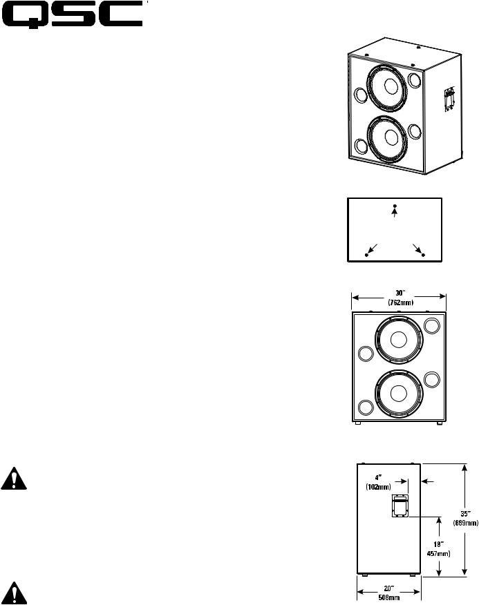
The LF-3215 dual 15” (381mm) low frequency enclosure is designed specifically for cinema applications. Meeting cinema requirements for extended low frequency response differentiates the LF-3215 from more conventional “rock-and-roll” woofer systems. The LF-3215 covers the frequency range from 32 Hertz to 1500 Hertz, depending upon the high frequency system requirements. With its tight spacing between woofers, the LF-3215 offers improved coupling and keeps coverage angles wide over a greater frequency range than more widely spaced designs.
The 300 watt, 15” transducers are well suited for cinema use. They feature 3” (76mm) voice coils, 120 oz.(3.4kg) ceramic magnets, and vented pole pieces to ensure cool operation. Cooler temperatures increase transducer lifespan and decrease the problem of power compression at high power levels. The suspension and voice coil of each transducer have been designed to provide low distortion and high impact bass at high power levels.
The enclosure is constructed of high quality medium density fiberboard panels with stiffening braces on all panels and features separate woofer chambers. This prevents over-excur- sion of a transducer caused by improper box loading in the rare event of a transducer failure. The eight stiffening braces reduce panel resonance.
Both internal and external port openings are fully radiused ensuring smooth air flow at high power. This prevents audible port turbulence noise.
With symmetrical port loading, bass ports are evenly spaced on each side of the transducers, making internal pressure more uniform across the back surface of the transducer. This prevents the cone from being displaced to one side or another by unbalanced forces, reducing the chance of driving the voice coil out of the center of the gap at high power levels.
Three T-nuts in the top of the enclosure provide easy mounting of QSC’s HF-63 high frequency system, or MH-1063 mid-high frequency system.
Enclosure is not designed to be suspended, flown, or rigged. Do not suspend, fly, or rig this enclosure.
This product is capable of producing sound pressure levels that can permanently damage human hearing. Always keep sound pressure levels in the listening area below levels that can damage human hearing.
Install in accordance with QSC Audio Product’s instructions and a licensed, professional engineer. Only use attachments, mounts, accessories, or brackets specified by QSC Audio Products, Inc. Refer all servicing to qualified personnel. Servicing is required when the apparatus has been damaged in any way.
WARNING! Before placing, installing, rigging, or suspending any speaker product, inspect all hardware, suspension, cabinets, transducers, brackets and associated equipment for damage. Any missing, corroded, deformed or non-load rated component could significantly reduce the strength of the installation, placement, or array. Any such condition severely reduces the safety of the installation and should be immediately corrected. Use only hardware which is rated for the loading conditions of the installation and any possible short-term unexpected overloading. Never exceed the rating of the hardware or equipment. Consult a licensed, professional engineer when any doubt or questions arise regarding a physical equipment installation.
Mounting points for midhigh or high frequency system
*TD-000173-00*
TD-000173-00 rev.C © Copyright 2004, QSC Audio Products, Inc.
QSC® is a registered trademark of QSC Audio Products, Inc. “QSC” and the QSC logo are registered with the U.S. Patent and Trademark Office
Connections
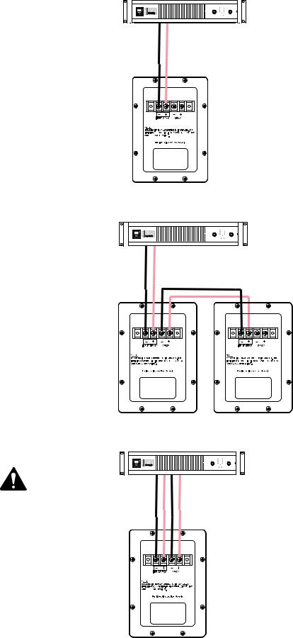
Normal Connection
The LF-3215 has barrier strip screw terminals for connection. The terminals accept up to #10 AWG (5.3mm2) stranded loudspeaker wiring. Use the largest wire size and shortest wire length possible for the application. Observe the polarity markings and keep polarity consistent throughout the system for best performance.
Parallel Connection of Second LF-3215
The terminals marker SPK2 may be used to connect another LF-3215 in parallel. Connect the wires as shown in the illustration, at right. Note: If the LF-3215’s internal wiring has been modified in any way, this may not function. If this is the case, remove the terminal cup and verify the presence of the factory yellow jumper and blue jumper wires; remedy as required or have the loudspeaker serviced.
Individual Transducer Connection (requires modification)
The transducers are wired in parallel inside the enclosure. If individual transducer connection is required, remove the terminal cup and remove the yellow and the blue jumper wires that are connected between the SPK1 and SPK2 terminals. Replace the terminal cup and mark the enclosure with a note of the modification.
Normal Connection Example:
Amplifier capable of driving 4 ohm loads
Parallel Connection Example:
Amplifier capable of driving 2 ohm loads
Individual Transducer
Connection Example:
CAUTION! Requires removal of terminal cup and removing both the yellow and the blue jumper wires that connect the SPK1 and SPK2 terminals.

LF-3215 Specifications (subject to change without notice)
Frequency Range: |
32 - 1500 Hertz (-6dB) |
|
28 - 3300 Hertz useable range (-10dB) |
Nominal Coverage: |
100° horizontal X 55° vertical at 600 Hertz |
Maximum Output: |
132.5 dB SPL calculated peak, 1 meter, half space, at rated rms power with 6 dB crest factor pink noise input, 25 - 250 Hertz. |
|
126.5 dBA SPL calculated maximum continuous, 1 meter. The dBA scale is typically used to identify sound sources |
|
which can cause permanent hearing loss. |
Impedance: |
4 ohms nominal |
|
4.1 ohms minimum, 180 Hertz |
|
55 ohms maximum, 21 Hertz |
Maximum Input Power: |
600 watts rms (8 hours of 6 dB crest factor pink noise, 40 - 400 Hertz) |
|
750 watts rms (2 hours of 6 dB crest factor pink noise, 40 - 400 Hertz) |
|
Recommended amplifier power capability1200 watts rms maximum into 4 ohms (per LF-3215) |
Sensitivity: |
98.5 dB half space, 97.5 dB full space, 35 - 1000 Hertz, 1 watt, 1 meter |
Recommended Processing: |
Subsonic filter below 30 Hertz, >18 dB per octave, maximum recommended crossover frequency is 1000 Hertz. QSC |
|
DSP configurations are available at www.qscaudio.com. Parameters for alternative processing hardware are available |
|
upon request. |
Connectors: |
Barrier strip screw terminals accept up to #10 AWG stranded wire. Four terminals: (two INPUT and two PARALLEL |
|
OUT). Transducers are internally wired in parallel. For independent transducer connection, remove blue jumper wire |
|
and yellow jumper wire on internal-side of terminal cup and mark enclosure accordingly. |
Transducers: |
Two 15” (381mm) high efficiency low frequency transducers featuring vented 3” (76mm) copper voice coils on Kapton® |
|
formers. High excursion/low distortion design, with extremely high power handling, and low thermal and port com- |
|
pression. |
Enclosure: |
Quasi B4 alignment, ported enclosure with fully flared ports, low turbulence symmetrical port design, tuned to 36 |
|
Hertz, constructed of medium density fibreboard and heavily braced. Features vandal resistant woofer mounting bolts. |
Size: |
30” wide X 35” high X 20” deep (762 mm X 889 mm X 508 mm) |
Weight: |
195 lbs. shipping, 172 lbs. net (88/78 kg.) |
SPL and Impedance vs. Frequency
SPL 2pi
SPL 4pi
SPL (dB)
Impedance
Frequency (Hertz)


 Impedance (ohms)

Warranty (USA only; other countries, see your dealer or distributor)
Disclaimer
QSC Audio Products, Inc. is not liable for any damage to amplifiers, or any other equipment that is caused by negligence or improper installation and/or use of this loudspeaker product.
QSC Audio Products 3 Year Limited Warranty
QSC Audio Products, Inc. (“QSC”) guarantees its products to be free from defective material and / or workmanship for a period of three (3) years from date of sale, and will replace defective parts and repair malfunctioning products under this warranty when the defect occurs under normal installation and use - provided the unit is returned to our factory or one of our authorized service stations via pre-paid transportation with a copy of proof of purchase (i.e., sales receipt). This warranty provides that the examination of the return product must indicate, in our judgment, a manufacturing defect. This warranty does not extend to any product which has been subjected to misuse, neglect, accident, improper installation, or where the date code has been removed or defaced. QSC shall not be liable for incidental and/or consequential damages. This warranty gives you specific legal rights. This limited warranty is freely transferable during the term of the warranty period.
Customer may have additional rights, which vary from state to state.
In the event that this product was manufactured for export and sale outside of the United States or its territories, then this limited warranty shall not apply. Removal of the serial number on this product, or purchase of this product from an unauthorized dealer, will void this limited warranty. Periodically, this warranty is updated. To obtain the most recent version of QSC’s warranty statement, please visit www.qscaudio.com. Contact us at 800-854-4079 or visit our website at www.qscaudio.com.
Contacting QSC Audio Products
Mailing address:QSC Audio Products, Inc. 1675 MacArthur Boulevard
Costa Mesa, CA 92626-1468 USA
Telephone Numbers:
Main Number (714) 754-6175
Sales & Marketing (714) 957-7100 or toll free (USA only) (800) 854-4079
Customer Service(714) 957-7150 or toll free (USA only) (800) 772-2834
Facsimile Numbers:
Sales & Marketing Fax(714) 754-6174
Customer Service Fax(714) 754-6173
World Wide Web:www.qscaudio.com E-mail:info@qscaudio.com service@qscaudio.com
QSC Audio Products, Inc. 1675 MacArthur Boulevard Costa Mesa, California 92626 USA ©2004 “QSC” and the QSC logo are registered with the U.S. Patent and Trademark Office.
Kapton® is a registered trademark of E.I. du Pont de Nemours and Company.
Manual del usuario de los sistemas de altavoces para salas de cine Altavoz de baja frecuencia LF-3215
Introducción
La caja doble de baja frecuencia de 15” (381 mm) del altavoz LF-3215 está diseñada específicamente para aplicaciones cinematográficas. El cumplimiento de los requisitos de las aplicaciones cinematográficas referentes a una respuesta extendida de baja frecuencia, es lo que distingue al altavoz LF-3215 de otros sistemas woofer tipo “rock-and-roll” más convencionales. El altavoz LF-3215 cubre un intervalo de frecuencia de 32 Hertzios a 1500 Hertzios, dependiendo de los requisitos del sistema de alta frecuencia. Con su espacio estrecho entre los woofers, el LF-3215 ofrece un mejora en el acoplamiento y mantiene la amplitud de los ángulos de cobertura sobre un mayor intervalo de frecuencia en comparación con diseños de espacio más grande.
Los transductores de 300 vatios y 15” son apropiados para uso en salas de cine. Cuentan con bobinas de voz de 3” (76 mm), imanes cerámicos de 120 onzas (3.4 kg) y polos multiventilados para asegurar una operación fría. Las temperaturas más frías aumentan la vida útil del transductor y disminuyen el problema de compresión de la potencia a niveles altos de potencia. La suspensión y la bobina de voz de cada transductor se han diseñado para brindar una baja distorsión y graves de alto impacto a altos niveles de potencia.
La caja está construida de paneles de cartón duro mediano de alta calidad con soportes de refuerzo en todos los paneles, y cuenta con cámaras separadas para los woofers. Esto previene la excursión excesiva de un transductor causada por la carga inadecuada de la caja, en el raro evento de falla del transductor. Los ocho soportes de refuerzo reducen la resonancia en el panel.
Ambas aberturas del puerto, la interna y la externa, están totalmente redondeadas, asegurando un flujo de aire uniforme a alta potencia. Esto evita ruido de turbulencia audible en el puerto.
Con la carga simétrica de los puertos, los puertos de graves están igualmente separados a cada lado de los transductores, haciendo que la presión interna sea más uniforme a través de la superficie posterior del transductor. Esto evita que el cono sea desplazado de un lado a otro por fuerzas no equilibradas, reduciendo la probabilidad de impulsar la bobina de voz fuera del centro del espacio a altos niveles de potencia.
Tres tuercas en T en la parte superior de la caja permiten el montaje fácil del sistema de alta frecuencia HF-63 o del sistema de frecuencia media alta MH-1063, ambos de QSC.
La caja no esta diseñada para montarse suspendida, en voladizo ni sobre arneses. No suspenda esta caja, no la monte en voladizo ni sobre arneses.
Este producto es capaz de producir niveles de presión del sonido que pueden causar daños permanentes al oído humano. Siempre mantenga los niveles de presión del sonido en un área de audición con un nivel menor que el que provoca daños al oído humano.
Instale de acuerdo con las instrucciones de QSC Audio Products y de un ingeniero profesional con la debida licencia. Sólo use piezas, montajes, accesorios y soportes especificados por QSC Audio Products, Inc. Refiera todo el servicio a personal calificado. Cuando el aparato haya sido dañado de alguna manera, es necesario proporcionarle servicio.
¡ADVERTENCIA! Antes de colocar, instalar, montar o suspender cualquier producto de altavoz, inspeccione todo el equipo físico, la suspensión, los armarios, los transductores, los soportes y el equipo asociado para detectar la existencia de daños.
Cualquier componente faltante, corroído, deformado, o sin carga nominal podría reducir significativamente la resistencia de la instalación, la colocación o la configuración. Cualquier condición de este tipo reduce gravemente la seguridad de la instalación y debe corregirse de inmediato. Use sólo herraje que esté clasificado para las condiciones de carga de la instalación y cualquier posible carga excesiva a corto plazo inesperada. Nunca exceda el valor nominal del equipo físico ni del dispositivo. Consulte a un ingeniero profesional con la debida licencia cuando surjan dudas o preguntas referentes a la instalación física del equipo.
Puntos de montaje para el sistema de alta frecuencia o el sistema de frecuencia media alta
TD-000173-00 rev. C © Derechos de autor 2004, QSC Audio Products, Inc.
QSC® es una marca comercial registrada de QSC Audio Products, Inc. “QSC” y el logotipo de QSC están registrados con la Oficina de Patentes y Marcas Comerciales de los Estados Unidos
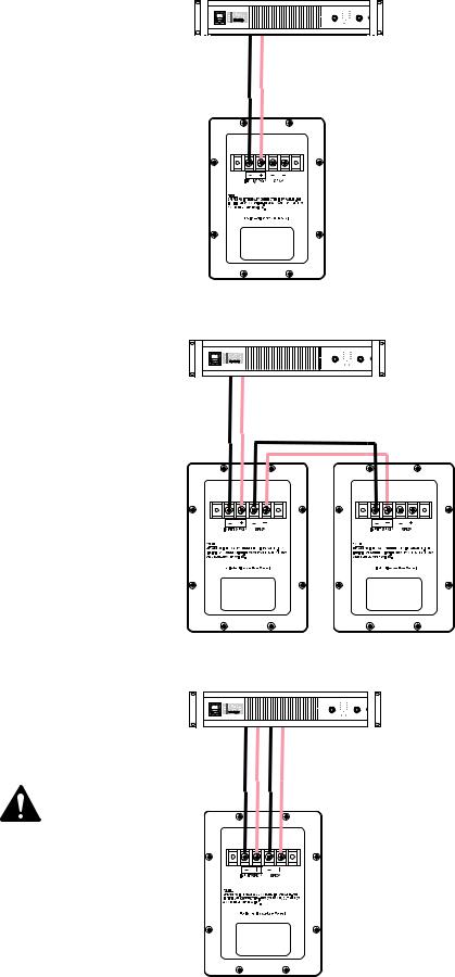
Conexiones
Conexión normal
El altavoz LF-3215 tiene terminales de tornillo de barra protectora para su conexión. Los terminales aceptan cableado trenzado de hasta #10 AWG (5.3 mm2) para altavoces. Use el alambre de calibre más grande y de longitud más corta posible para la aplicación. Observe las marcas de polaridad y mantenga la polaridad uniforme en todo el sistema para permitir el mejor rendimiento.
Ejemplo de una conexión normal: |
Amplificador con capacidad de accionamiento de cargas de 4 ohmios
Conexión en paralelo de un segundo LF3215
Los terminales marcados SPK2 se pueden usar para conectar en paralelo otro altavoz LF-3215. Conecte los cables como se muestra en la ilustración, a la derecha. Nota: si el cableado interno de LF-3215 se ha modificado de alguna manera, es posible que no funcione. En este caso, quite la cúpula del terminal y verifique la presencia de alambres amarillos y azules de puentes instalados en fábrica; corrija el problema según se requiera, o solicite que den servicio al altavoz.
Conexión del transductor individual (requiere modificación)
Los transductores están conectados en paralelo dentro de la caja. Si se requiere la conexión del transductor individual, quite la cúpula del terminal y quite los alambres amarillo y azul del puente que están conectados entre los terminales SPK1 y SPK2. Vuelva a colocar la cúpula del terminal y marque la caja con una nota que indique la modificación.
Ejemplo de conexión en paralelo:
Ejemplo de la conexión
de un transductor individual:
¡PRECAUCIÓN! Requiere desmontar la cúpula del terminal y los alambres amarillo y azul que conectan los terminales SPK1 y SPK2.
Amplificador con capacidad de accionamiento de cargas de 2 ohmios
 Loading...