


1675 MacArthur Blvd., Costa Mesa, CA, 92626 USA
Main Number (714) 754-6175 Sales & Marketing (714) 957-7100 or toll free (USA only) (800) 854-4079 Customer Service(714) 957-7150 or toll free (USA only) (800) 772-2834
Cinema Loudspeaker Systems User Manual
HF-75 High Frequency Component
Introduction
The HF-75 is the high frequency component of the SC-412 and SC-422 twoway, biamplified screen channel loudspeakers for high performance cinema applications. The system is shipped as two separate components: the HF-75 high frequency system and the LF-4115 or LF-4215 woofer system.
The HF-75 high-frequency system features a large format, 3” (75mm) titanium diaphragm compression driver mounted on a custom designed highfrequency cinema horn with an adjustable pan and tilt bracket. The horn features broad horizontal and vertical coverage angles to ensure coverage of every seat in the auditorium. The horn is a low-distortion waveguide providing highly articulate dialogue without the “honky” coloration associated with conventional horn loudspeakers.
The HF-75 includes a driver protection and equalization network. DC blocking capacitors protect against DC or low-frequency signals that would likely destroy an unprotected driver. Power limiter circuitry protects the driver from over-powering and a response correction filter smoothes the frequency response of the horn/driver combination. The driver and equalization network provides for more reliable operation, ensuring the show will go on.
The HF-75 components come pre-assembled to reduce field assembly time. Three bolts are all that are required to secure the HF-75 to the top of the low frequency enclosure.
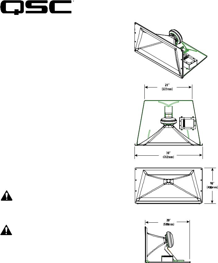
Mounting
Refer to the illustration for mounting information. The HF-75 attaches to the top of the LF-4115 or LF-4215 with three 5/16-18 bolts, 0.75” long, with lock washers. We recommend the use of serviceable thread locking compound when installing the bolts to prevent loosening due to vibration. Aim the horn in the horizontal plane (pan) before tightening. Adjust the vertical tilt with the bracket adjustment.
Install in accordance with QSC Audio Product’s instructions and a licensed, professional engineer. Only use attachments, mounts, accessories, or brackets specified by QSC Audio Products, Inc. Refer all servicing to qualified personnel. Servicing is required when the apparatus has been damaged in any way.
WARNING! Before placing, installing, rigging, or suspending any speaker product, inspect all hardware, suspension, cabinets, transducers, brackets and associated equipment for damage. Any missing, corroded, deformed or non-load rated component could significantly reduce the strength of the installation, placement, or array. Any such condition severely reduces the safety of the installation and should be immediately corrected. Use only hardware which is rated for the loading conditions of the installation and any possible short-term unexpected overloading. Never exceed the rating of the hardware or equipment. Consult a licensed, professional engineer when any doubt or questions arise regarding a physical equipment installation.
*TD-000149-00*
TD-000149-00 rev.D © Copyright 2003, 2004 QSC Audio Products, Inc.
QSC® is a registered trademark of QSC Audio Products, Inc. “QSC” and the QSC logo are registered with the U.S. Patent and Trademark Office
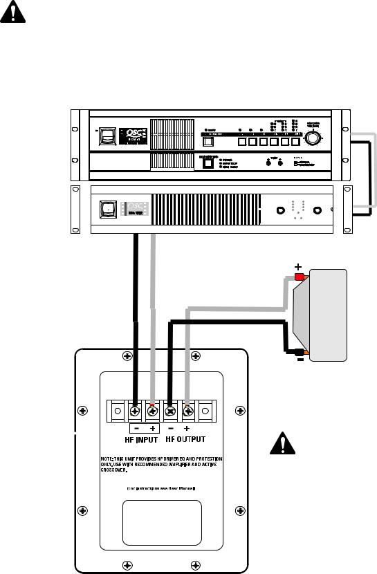
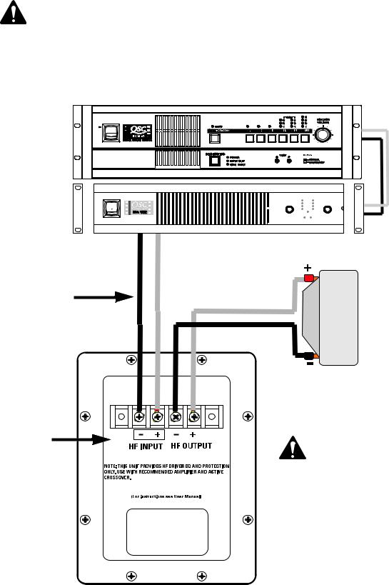
Connections
The HF-75 has barrier strip screw terminals that accept up to #10 AWG stranded loudspeaker wire.
HF INPUT Terminals
Connect the amplifier’s output signal to the loudspeaker’s HF INPUT terminals. Observe proper polarity; amplifier + signal to loudspeaker + HF INPUT, amplifier - signal to loudspeaker - HF INPUT. Use the largest wire size and shortest length for the application.
NOTE! Do not apply full range signal to the HF-75! There is no crossover in the HF-75, only a compensation/ delay network. All required signal processing must be done upstream of the HF-75. Maintain proper loudspeaker connection polarity throughout the entire system for maximum performance.
HF OUTPUT Terminals
The HF OUTPUT terminals are factory-connected to the compression driver. These terminals should ONLY be connected to the HF75’s compression driver.
QSC DCM or other active crossover
Amplifier |
Processed high frequency program signal 
HF-75 compression driver
HF-75 connection terminals 
Note: The HF-75 connection enclosure does not contain a crossover network! Ensure only high frequency signal is applied to HF INPUT terminals or compression driver damage will occur.

HF-75 Specifications (subject to change without notice)
Frequency Range: |
600 - 16k Hz (-6 dB, full space) |
|
Nominal Coverage: |
90° horizontal X +15° to -35° vertical (50° total, adjustable mount provides for vertical plane adjustments. The |
|
|
horizontal plane can be adjusted by altering mounting position on the LF-4215 enclosure before tightening bolts. |
|
DI: |
9.0 dB (600 to 16,000 Hertz average) |
|
Q: |
8.0 |
(600 to 16,000 Hertz average) |
Maximum Output: |
133 |
dB SPL calculated peak, 1 meter, half space. |
Impedance: |
8 ohms nominal |
|
|
8.0 ohms minimum at 3,000 Hertz |
|
|
104 ohms maximum at 475 Hertz |
|
Maximum Input Power: |
60 watts rms (100 hours of 6 dB crest factor pink noise, 500 to 20,000 Hertz, IEC method) |
|
|
80 watts rms (2 hours of 6 dB crest factor pink noise, 60 - 6,000 Hertz, AES method) |
|
Sensitivity: |
108 dB half space, 1 watt, 1 meter |
|
Crossover Frequency: |
700 Hertz or higher, 24 dB per octave |
|
Connectors: |
Barrier strip screw terminals accept up to #10 AWG stranded wire. Four terminals: (two HF INPUT and two post |
|
|
compensation HF OUTPUT). HF OUTPUT factory wired to compression driver. |
|
Transducers: |
1.5” (38mm) exit, 3.0” (76mm) titanium diaphragm compression driver. |
|
Mounting Hardware: |
Attaches to top of low frequency cabinet using three 5/16”-18 x 3/4” long bolts. |
|
Size: |
30” wide X 16” high X 20” deep (762mm X 406mm X 508mm) |
|
Weight: |
50 lbs. (shipping), 40 lbs. (net), 22.7/18.4 kilograms |
|
SPL and Impedance vs. Frequency
|
SPL |
SPL (dB) |
Impedance (Ohms) |
|
Impedance |
Frequency (Hertz)

Warranty (USA only; other countries, see your dealer or distributor)
Disclaimer
QSC Audio Products, Inc. is not liable for any damage to amplifiers, or any other equipment that is caused by negligence or improper installation and/or use of this loudspeaker product.
QSC Audio Products 3 Year Limited Warranty
QSC Audio Products, Inc. (“QSC”) guarantees its products to be free from defective material and / or workmanship for a period of three (3) years from date of sale, and will replace defective parts and repair malfunctioning products under this warranty when the defect occurs under normal installation and use - provided the unit is returned to our factory or one of our authorized service stations via pre-paid transportation with a copy of proof of purchase (i.e., sales receipt). This warranty provides that the examination of the return product must indicate, in our judgment, a manufacturing defect. This warranty does not extend to any product which has been subjected to misuse, neglect, accident, improper installation, or where the date code has been removed or defaced. QSC shall not be liable for incidental and/or consequential damages. This warranty gives you specific legal rights. This limited warranty is freely transferable during the term of the warranty period.
Customer may have additional rights, which vary from state to state.
In the event that this product was manufactured for export and sale outside of the United States or its territories, then this limited warranty shall not apply. Removal of the serial number on this product, or purchase of this product from an unauthorized dealer, will void this limited warranty. Periodically, this warranty is updated. To obtain the most recent version of QSC’s warranty statement, please visit www.qscaudio.com. Contact us at 800-854-4079 or visit our website at www.qscaudio.com.
Contacting QSC Audio Products
Mailing address:QSC Audio Products, Inc. 1675 MacArthur Boulevard
Costa Mesa, CA 92626-1468 USA
Telephone Numbers:
Main Number (714) 754-6175
Sales & Marketing (714) 957-7100 or toll free (USA only) (800) 854-4079
Customer Service(714) 957-7150 or toll free (USA only) (800) 772-2834
Facsimile Numbers:
Sales & Marketing Fax(714) 754-6174
Customer Service Fax(714) 754-6173
World Wide Web:www.qscaudio.com E-mail:info@qscaudio.com service@qscaudio.com
QSC Audio Products, Inc. 1675 MacArthur Boulevard Costa Mesa, California 92626 USA ©2003, 2004 “QSC” and the QSC logo are registered with the U.S. Patent and Trademark Office.
1675 MacArthur Blvd., Costa Mesa, CA, 92626 EE.UU.
Número principal +1 (714) 754-6175 Ventas y Comercialización +1 (714) 957-7100 o línea sin costo (sólo para EE.UU.) +1 (800) 854-4079
Servicio al cliente +1 (714) 957-7150 o gratis (sólo EE.UU.) +1 (800) 772-2834
Manual del usuario de los sistemas de altavoces para salas de cine
Componente de alta frecuencia HF-75
Introducción
El HF-75 es el componente de alta frecuencia de los altavoces bidireccionales SC-412 y SC-422 de canal de pantalla biamplificada, para aplicaciones cinematográficas de alto rendimiento. El sistema se envía como dos componentes separados: el sistema de alta frecuencia HF-75 y el sistema de woofer LF-4115 o LF-4215.
El sistema HF-75 de alta frecuencia tiene un formato grande, un excitador de compresión con diafragma de titanio de 3” (75 mm) montado en un cuerno cinematográfico de alta frecuencia de diseño bajo especificaciones con un soporte de movimiento horizontal y vertical ajustable. El cuerno tiene amplios ángulos de cobertura horizontal y vertical para asegurar la cobertura de cada asiento del auditorio. El cuerno es una guiaonda de baja deformación que proporciona un diálogo altamente articulado sin la coloración de "bocina" asociada con los altavoces de cuerno convencionales.
El HF-75 incluye protección del excitador y una red de ecualización. Los capacitores de bloqueo de CC protegen contra señales de CC o de baja frecuencia que probablemente destruirían un excitador no protegido. El circuito limitador de potencia protege al excitador contra las sobrecargas, y un filtro de corrección de respuesta suaviza la respuesta de frecuencia de la combinación cuerno/excitador. El excitador y la red de ecualización proporcionan una operación más confiable, asegurando la continuación del espectáculo.
Los componentes del sistema HF-75 vienen ya montados para reducir el tiempo de montaje en el campo. Tres pernos es todo lo que se requiere para fijar el HF75 en la parte superior de la caja del sistema de baja frecuencia.
Montaje
Vea la información sobre el montaje en la ilustración. El HF-75 se conecta en la parte superior del LF-4115 o LF-4215 con tres pernos de 5/16-18, de 0.75” de largo, con arandelas de fijación. Recomendamos el uso de un compuesto duradero para fijación de roscas al instalar los pernos para evitar que se aflojen debido a la vibración. Oriente el cuerno en el plano horizontal antes de apretarlo. Ajuste la posición vertical con el soporte de ajuste.
Instale de acuerdo con las instrucciones de QSC Audio Products y de un ingeniero profesional con la debida licencia. Sólo use piezas, montajes, accesorios o soportes especificados por QSC Audio Products, Inc. Refiera todo el servicio a personal calificado. Cuando el aparato haya sido dañado de alguna manera, es necesario proporcionarle servicio.
¡ADVERTENCIA! Antes de colocar, instalar, montar o suspender cualquier producto de altavoz, inspeccione todo el equipo físico, la
suspensión, los armarios, los transductores, los soportes y el equipo asociado para detectar la existencia de daños. Cualquier
componente faltante, corroído, deformado, o sin carga nominal
podría reducir significativamente la resistencia de la instalación, la colocación o la configuración. Cualquier condición de este tipo
reduce gravemente la seguridad de la instalación y debe corregirse
de inmediato. Use sólo herraje que esté clasificado para las condiciones de carga de la instalación y cualquier posible carga exce-
siva a corto plazo inesperada. Nunca exceda el valor nominal del equipo físico ni del dispositivo. Consulte a un ingeniero profesional con la debida licencia cuando surjan dudas o preguntas referentes
a la instalación física del equipo.
TD-000149-00 rev.D © Derechos de autor 2003, 2004 QSC Audio Products, Inc.
QSC® es una marca comercial registrada de QSC Audio Products, Inc. “QSC” y el logotipo de QSC están registrados con la Oficina de Patentes y Marcas Comerciales de los Estados Unidos
Conexiones
El HF-75 tiene terminales de tornillo de barra protectora que aceptan alambre trenzado de calibre de hasta #10 AWG para altavoces.
Terminales de ENTRADA de HF
Conecte la señal de salida del amplificador en los terminales de ENTRADA de HF del altavoz. Observe la polaridad adecuada; amplificador + señal al altavoz + ENTRADA de HF, amplificador - señal al altavoz - ENTRADA de HF. Use el alambre de calibre más grande y de longitud más corta para la aplicación.
¡NOTA! Mantenga la polaridad adecuada en la conexión del altavoz en todo el sistema para obtener el máximo rendimiento. ¡No aplique una señal de intervalo total al HF-75! No hay cruce en el HF-75, sólo una red de compensación/demora. Todo el procesamiento de señales requerido debe hacerse antes del HF-75.
Terminales de SALIDA de HF
Los terminales de SALIDA de HF se conectan en fábrica al excitador de compresión. Estos terminales SÓLO se deben conectar al excitador de compresión del HF-75.
DCM de QSC u otro cruce activo
Amplificador |
Señal procesada del programa de alta frecuencia
Excitador de compresión del HF-75
Terminales de con-
exión del HF-75
Nota: ¡La caja de conexión del HF-75 no contiene una red de cruce! Asegúrese que sólo se aplique la señal de alta frecuencia a los terminales de ENTRADA de HF, porque de lo contrario, pueden ocurrir daños al excitador de compresión.
 Loading...