

QSC SC-312 Owners manual
Features
• Two-way, bi-amplified screen channel system
• SC-312 provides 90° horizontal by +20° to -30° vertical coverage
• Low distortion waveguide provides highly articulate dialogue
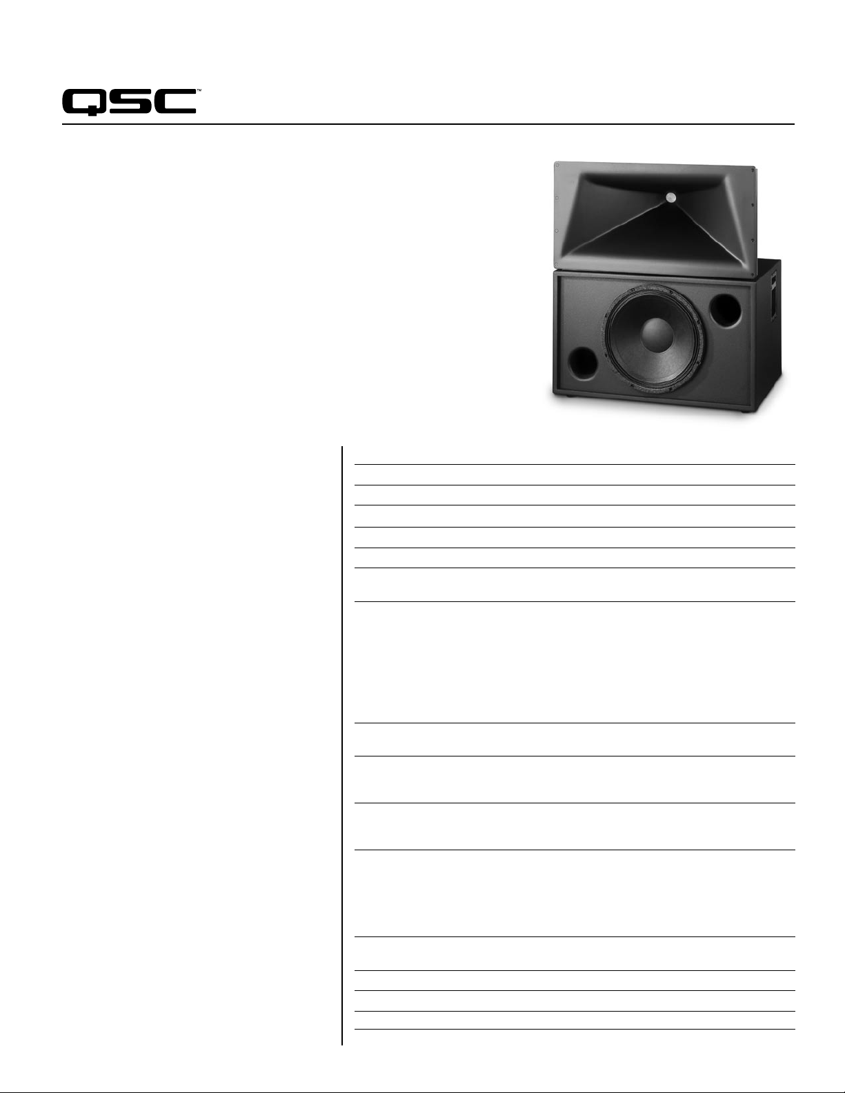
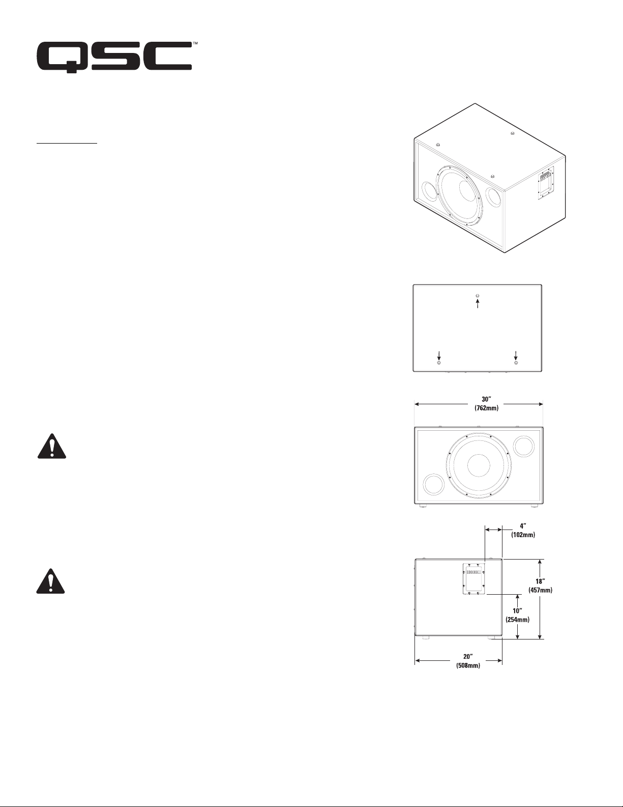
SC-312
Cinema Loudspeaker System
• Shallow depth (20
") facilitates installation
Developed specifically for the unique requirements
of professional motion picture playback, the SC-312
extends QSC’s commitment to the cinema market. As
a member of the DCS Digital Cinema Speaker Series,
the SC-312 is a two-way, bi-amplified screen channel
loudspeaker system comprised of two main units—the
HF-63 high frequency system and the LF-3115 lowfrequency system.
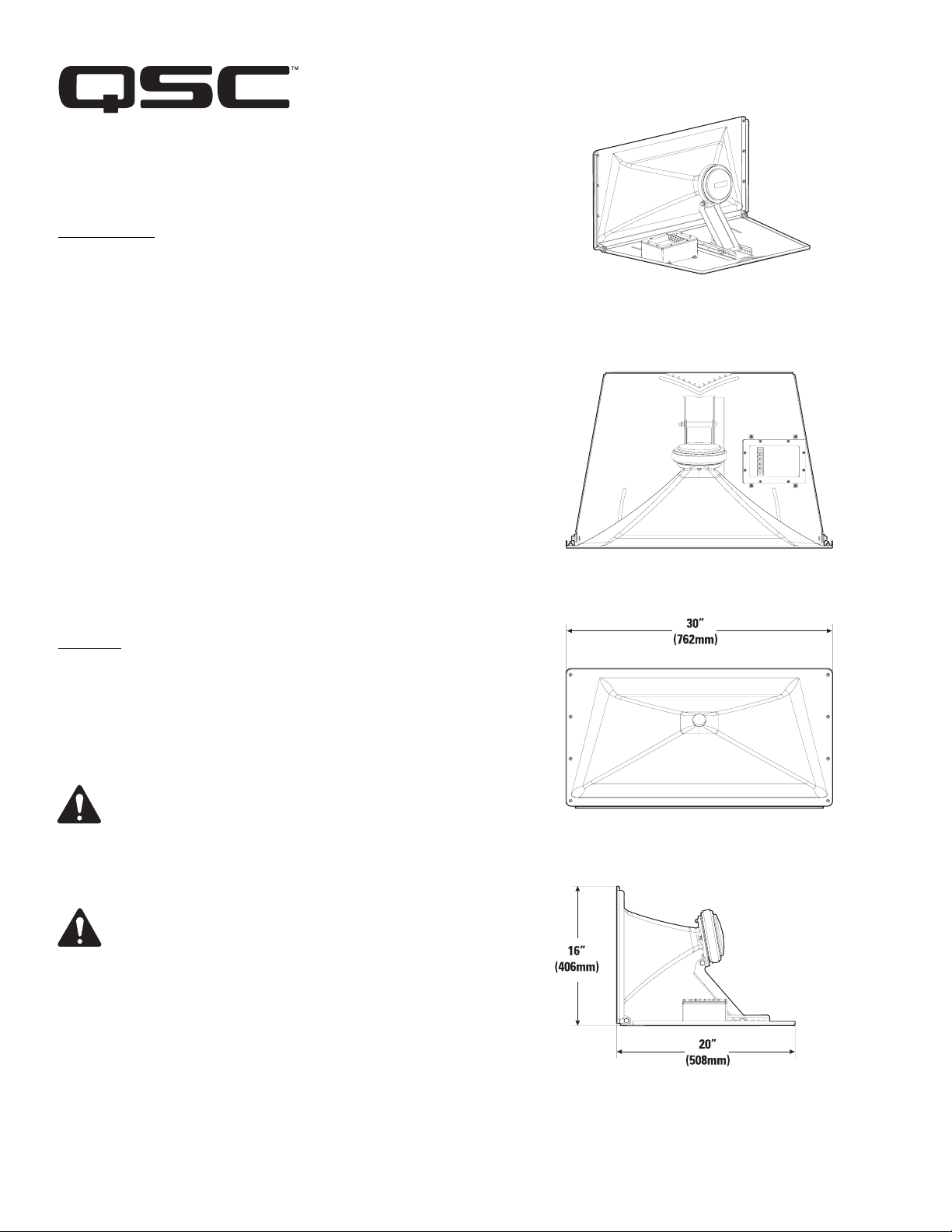
The HF-63 high-frequency system features a 2.5"
(63mm) titanium diaphragm compression driver
mounted on a custom designed high frequency
cinema horn with an adjustable pan and tilt bracket.
The HF-63 includes a driver protection and equalization
network. DC blocking capacitors protect against DC or
low-frequency signals that would likely destroy an
unprotected driver. Power limiter circuitry protects the
driver from overpowering and a response correction
filter smoothes the frequency response of the horn/
driver combination. The driver and equalization
network provides for more reliable operation, ensuring
the show will go on.
The LF-3115 15" (381mm) low-frequency enclosure
is designed specifically to address the extended lowfrequency response required for cinema applications.
The LF-3115 covers the frequency range from
35 Hz to 1000 Hz, depending upon the highfrequency system requirements.
The SC-312 is designed for ease of installation.
The HF-63 components come pre-assembled to
reduce field assembly time. Three bolts are all that
are required to secure the HF-63 to the top of the
LF-3115 enclosure.
Specifications SC-312
Nominal Coverage 90° horizontal x +20 to -30° vertical
Frequency Range 33 Hz - 16 kHz (-6 dB)
Crossover Frequency 1000 Hz, 24 dB per octave
LF-3115 HF-63
Impedance 8Ω 8Ω
Sensitivity 1 watt /1 meter, 95.5 dB 107.5 dB
half space
Maximum Input Power
8 hours of 6 db crest factor 300 W RMS 40 W RMS
IEC 268 noise spectrum
2 hours of 6 db crest factor 400 W RMS 60 W RMS
pinknoise, 50 Hz - 20 kHz,
AES method
Recommended Amplifier Power 600 W RMS maximum 100 W RMS maximum
Recommended Processing Subsonic filter below 30 Hz, 4th order LR crossover at 1000 Hz
> 18 dB per octave
Connectors Barrier strip screw terminals Barrier strip screw terminals
Transducers One 15" (381mm) high efficiency, 1.5" (38mm) exit, 2.5" titanium
Enclosure Quasi B4 alignment, ported Tilt/Pan Bracket
Dimensions (HWD) 18.5" x 30" x 20.3" 16" x 30" x 20"
(470 mm x 762 mm x 516 mm) (406 mm x 762 mm x 508 mm)
Weight - Net 83 lbs (38 kg) 40 lbs (18.4 kg)
System Weight 123 lbs (56.4 kg)
Baffle Cut-Out 35.5" x 32"
1) Maximum input power tested in accordance with IEC 268-5 recommendations, 50 Hz - 20 kHz band limiting, 6 dB signal crest factor.
1
accept up to #10 AWG accept up to #10 AWG
stranded wire stranded wire
extended bass woofer featuring a diaphragm compression driver
3" copper voice coil
enclosure with fully flared ports, ±10° vertical tilt
symmetrical port design, tuned to ±10° horizontal pan
36 Hz, constructed of MDF and
heavily braced. Features vandal
resistant woofer mounting bolts
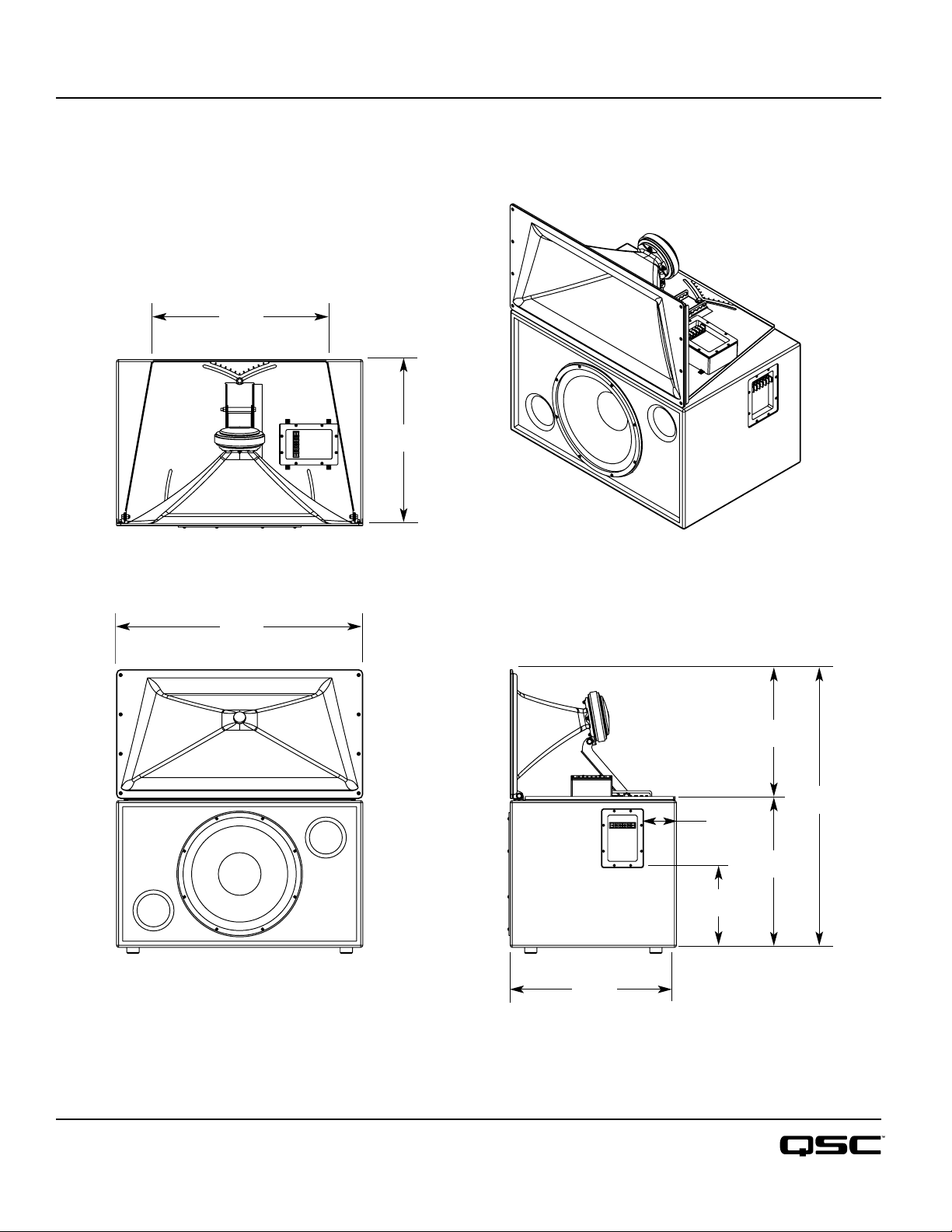
SC-312
Dimensions
Top
21.53"
546.9 mm
20.25"
514.4 mm
30"
762 mm
Front
Side
20.25"
514.4 mm
4"
101.6 mm
9.7"
246.4 mm
15.46"
392.6 mm
33.83"
859.3 mm
18.38"
466.8 mm
Specifications subject to change without notice.
1675 MacArthur Boulevard • Costa Mesa, CA 92626 • Ph: 800/854-4079 or 714/957-7100 • Fax: 714/754-6174
SC-312 Spec Sheet - 03/10/06
qscaudio.com
1675 MacArthur Blvd., Costa Mesa, CA, 92626 USA
Main Number (714) 754-6175 Sales & Marketing (714) 957-7100 or toll free (USA only) (800) 854-4079
Customer Service(714) 957-7150 or toll free (USA only) (800) 772-2834
Cinema Loudspeaker Systems User Manual
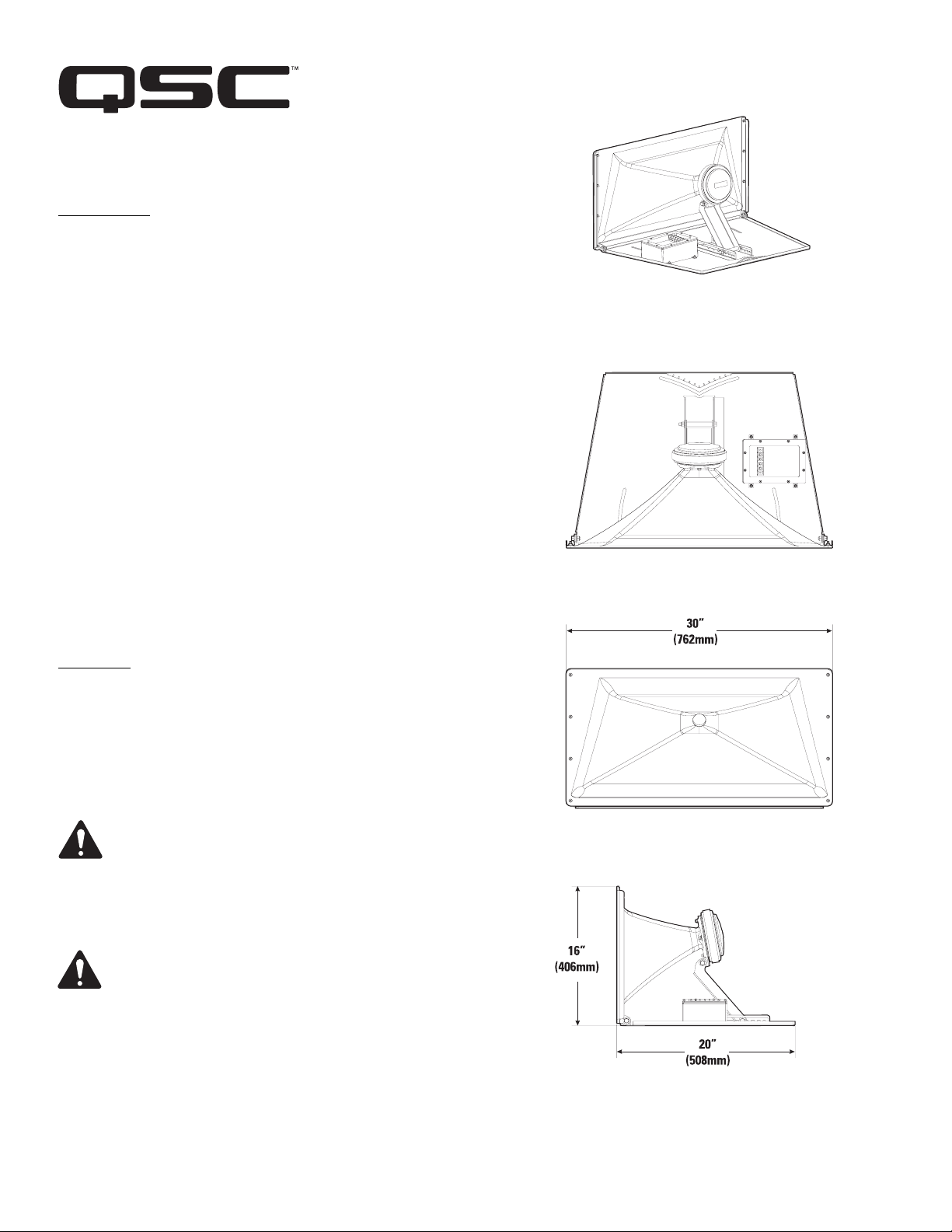
HF-63 High Frequency Component
Introduction
The HF-63 is the high frequency component of two-way, biamplified screen
channel loudspeaker systems for high performance cinema applications. It
was designed to operate with and be directly mounted on QSC’s LF-3115 or
LF-3215 cinema woofer.
The HF-63 high-frequency system features a large format, 2.5” (63.5mm)
titanium diaphragm compression driver mounted on a custom designed highfrequency cinema horn with an adjustable pan and tilt bracket. The horn features broad horizontal and vertical coverage angles to ensure coverage of
every seat in the auditorium. The horn is a low-distortion waveguide providing highly articulate dialogue without coloration associated with conventional horn loudspeakers.
The HF-63 includes a driver protection and equalization network to assure
reliable operation. DC blocking capacitors protect against DC or low-frequency signals that could damage an unprotected driver. Power limiter circuitry protects the driver from over-powering and a response correction filter
smoothes the frequency response of the horn/driver combination. Outboard
processing is required, however, as the response correction filter is not a
crossover.
The HF-63 components come pre-assembled to reduce field assembly time.
Three bolts are all that are required to secure the HF-63 to the top of a QSC
low frequency enclosure.
Mounting
Refer to the illustration for mounting information. The HF-63 attaches to the
top of the LF-3115 or LF-3215 with three 5/16-18 bolts, 0.75” long, with lock
washers. This hardware ships installed on the low frequency cabinet. We
recommend the use of serviceable thread locking compound when installing
the bolts to prevent loosening due to vibration. Aim the horn in the horizontal plane (pan) before tightening. Adjust the vertical tilt with the bracket
adjustment.
Install in accordance with QSC Audio Product’s instructions
and a licensed, professional engineer. Only use attachments,
mounts, accessories, or brackets specified by QSC Audio
Products, Inc. Refer all servicing to qualified personnel. Servicing is required when the apparatus has been damaged in
any way.
WARNING! Before placing, installing, rigging, or suspending
any speaker product, inspect all hardware, suspension, cabinets, transducers, brackets and associated equipment for
damage. Any missing, corroded, deformed or non-load rated
component could significantly reduce the strength of the
installation, placement, or array. Any such condition
severely reduces the safety of the installation and should be
immediately corrected. Use only hardware which is rated for
the loading conditions of the installation and any possible
short-term unexpected overloading. Never exceed the rating
of the hardware or equipment. Consult a licensed, professional engineer when any doubt or questions arise regarding
a physical equipment installation.
*TD-000149-00*
“QSC” and the QSC logo are registered with the U.S. Pa tent and Trademark Office
QSC® is a registered trademark of QSC Audio Products, Inc.
© Copyright 2004, QSC Audio Products, Inc.
TD-000170-00 rev.C
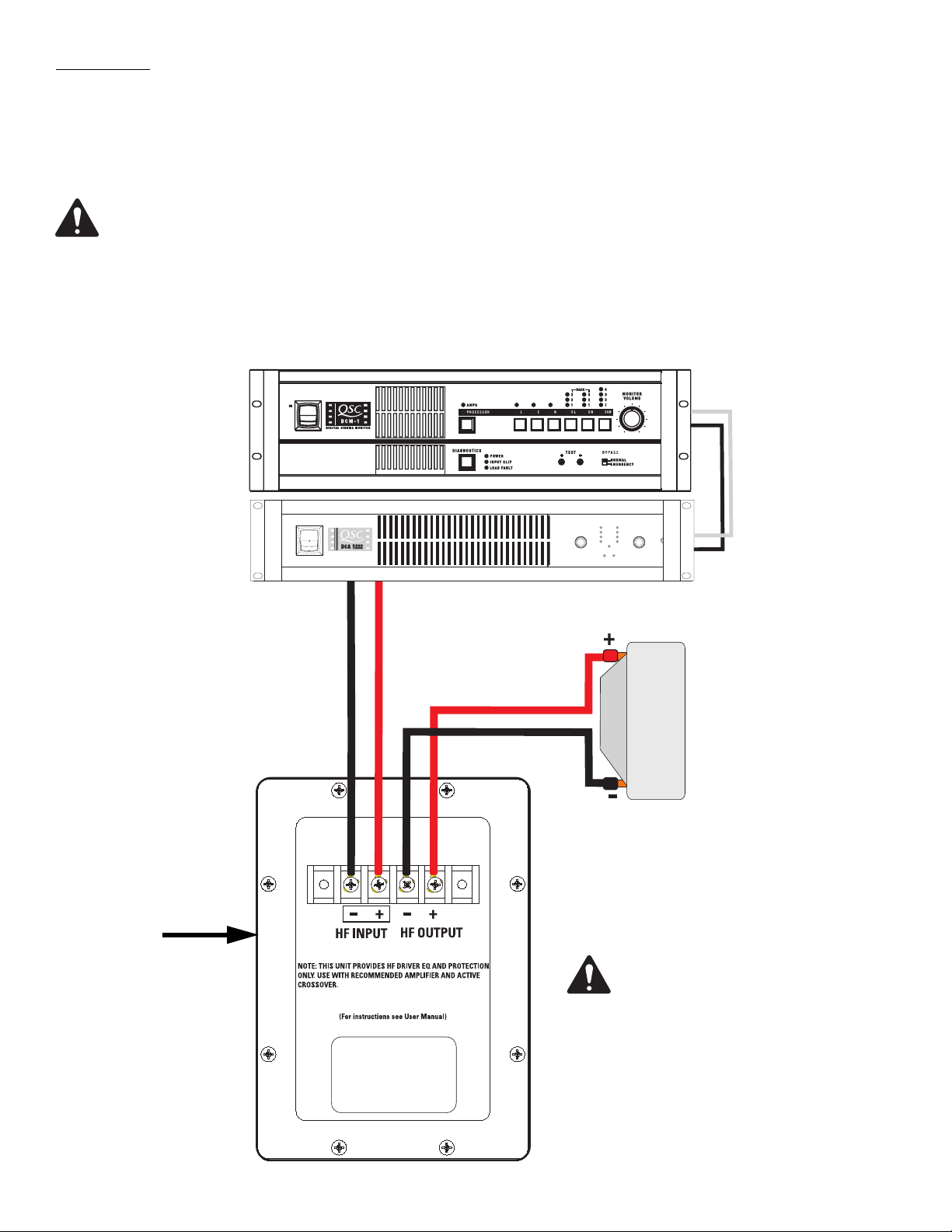
Connections
HF INPUT Terminals
The HF-63 has barrier strip screw terminals that accept up to #10 AWG (5.3mm
high frequency output signal to the loudspeaker’s HF INPUT terminals. Observe proper polarity; amplifier’s + signal to loudspeaker +
HF INPUT, amplifier’s - signal to loudspeaker - HF INPUT. Use the largest wire size and shortest wire length for the application.
NOTE! Maintain proper loudspeaker connection polarity throughout the entire system for maximum performance.
Do not apply full range signal to the HF-63! There is no crossover in the HF-63, only an equalization and protection
network. All required signal processing must be done before the signal is applied to the HF-63.
HF OUTPUT Terminals
The HF OUTPUT terminals are factory-connected to the compression driver. These terminals should ONLY be connected to the HF-63’s
compression driver.
QSC DCM or other
active crossover
Amplifier
2
) stranded loudspeaker wire. Connect the amplifier’s
HF-63 connection terminals
Processed high
frequency program signal
Compression
Driver
Note: The HF-63 connection enclosure
does not contain a crossover network!
Ensure only high frequency signal is
applied to HF INPUT terminals or compression driver damage will occur.
HF-63 Specifications (subject to change without notice)
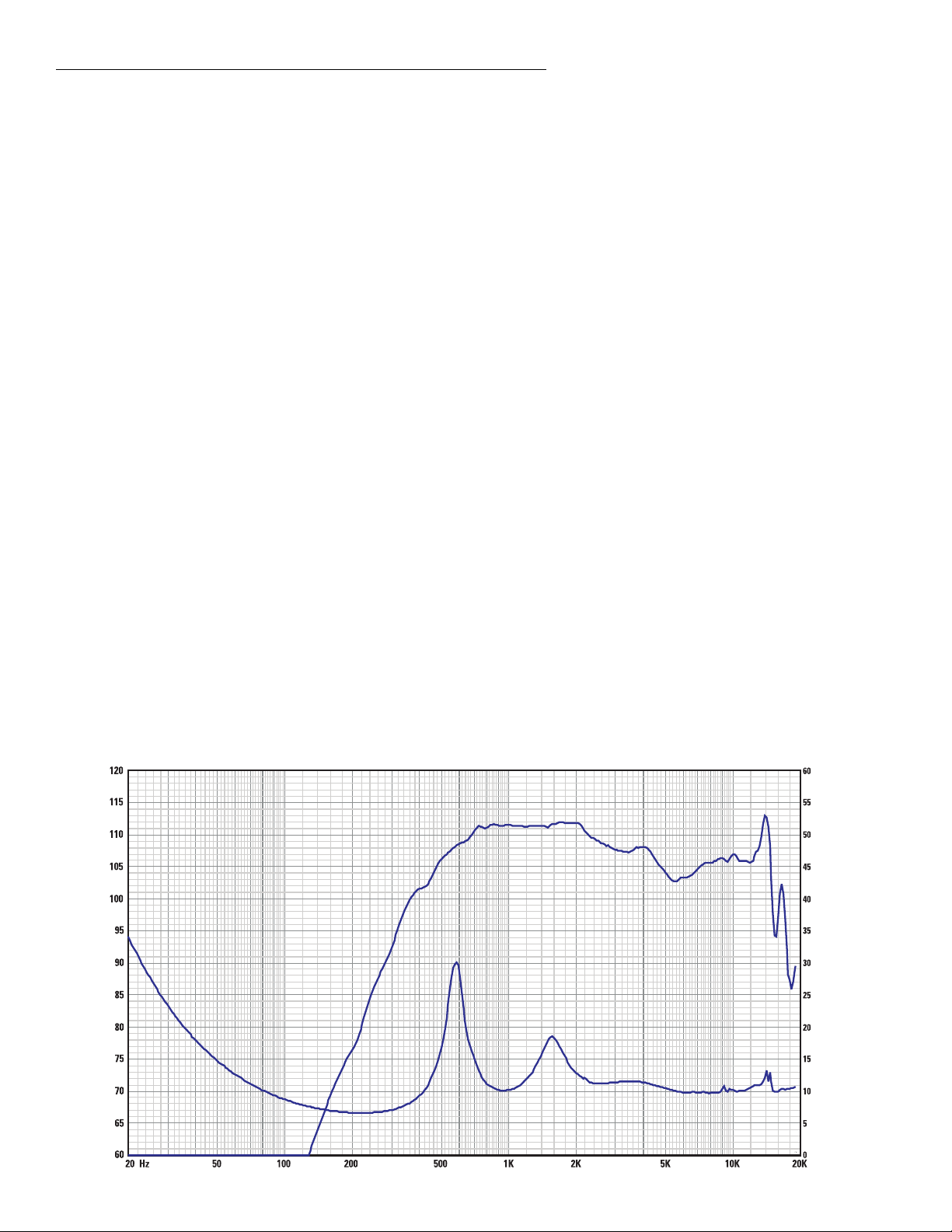
Frequency Range: 400 - 16k Hz (-6 dB, full space)
Nominal Coverage: 90° horizontal X +15 to -35° vertical (50° total, adjustable mount provides for vertical plane adjustments. The hori-
zontal plane can be adjusted by altering mounting position on the low frequency enclosure before tightening bolts.
DI: 9.0 dB (600 to 16,000 Hertz average)
Q: 8.0 (600 to 16,000 Hertz average)
Maximum Output: 131.5 dB SPL calculated peak, 1 meter, half space.
Impedance: 8 ohms nominal
9.0 ohms minimum at 8,000 Hertz
30 ohms maximum at 475 Hertz
Maximum Input Power: 50 watts rms (8 hours of 6 dB crest factor pink noise, 1,000 to 10,000 Hertz)
60 watts rms (2 hours of 6 dB crest factor pink noise, 1,000 - 10,000 Hertz, AES method)
Sensitivity: 107.5 dB half space, 1 watt, 1 meter
Crossover Frequency: 1,000 Hertz or higher, 24 dB per octave
Connectors: Barrier strip screw terminals accept up to #10 AWG stranded wire. Four terminals: (two HF INPUT and two post
compensation HF OUTPUT). HF OUTPUT factory wired to compression driver.
Transducers: 1.5” (38mm) exit, 2.5” (63.5mm) titanium diaphragm compression driver.
Mounting Hardware: Attaches to top of the low frequency cabinet using three 5/16”-18 x 3/4” long bolts.
Size: 30” wide X 16” high X 20” deep (762mm X 406mm X 508mm)
Weight: 50 lbs. (shipping), 40 lbs. (net), 22.7/18.4 kilograms
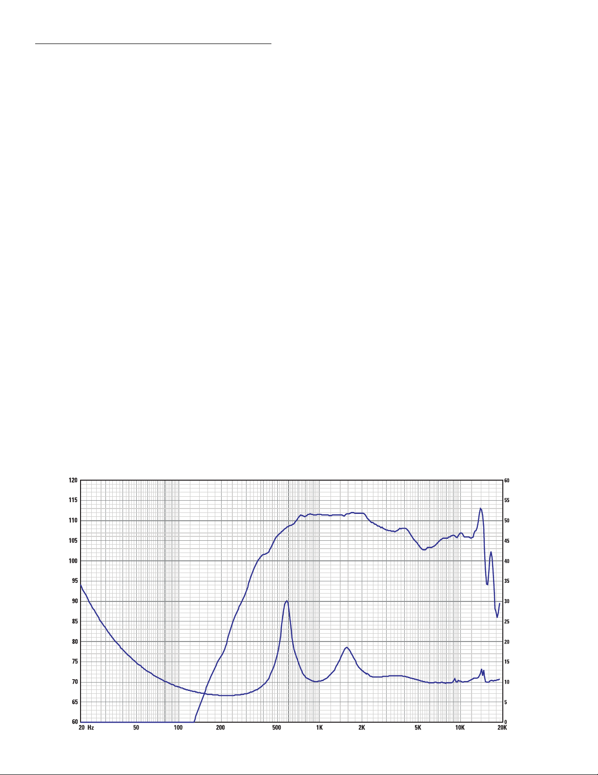
SPL and Impedance vs. Frequency
SPL
SPL (dB)
Frequency (Hertz)
Impedance (Ohms)
Impedance

Warranty (USA only; other countries, see your dealer or distributor)
Disclaimer
QSC Audio Products, Inc. is not liable for any damage to amplifiers, or any other equipment that is caused by negligence or
improper installation and/or use of this loudspeaker product.
QSC Audio Products 3 Year Limited Warranty
QSC Audio Products, Inc. (“QSC”) guarantees its products to be free from defective material and / or workmanship for a period
of three (3) years from date of sale, and will replace defective parts and repair malfunctioning products under this warranty
when the defect occurs under normal installation and use - provided the unit is returned to our factory or one of our authorized
service stations via pre-paid transportation with a copy of proof of purchase (i.e., sales receipt). This warranty provides that
the examination of the return product must indicate, in our judgment, a manufacturing defect. This warranty does not extend
to any product which has been subjected to misuse, neglect, accident, improper installation, or where the date code has been
removed or defaced. QSC shall not be liable for incidental and/or consequential damages. This warranty gives you specific
legal rights. This limited warranty is freely transferable during the term of the warranty period.
Customer may have additional rights, which vary from state to state.
In the event that this product was manufactured for export and sale outside of the United States or its territories, then this limited warranty shall not apply. Removal of the serial number on this product, or purchase of this product from an unauthorized
dealer, will void this limited warranty. Periodically, this warranty is updated. To obtain the most recent version of QSC’s warranty statement, please visit www.qscaudio.com. Contact us at 800-854-4079 or visit our website at www.qscaudio.com.
Contacting QSC Audio Products
Mailing address:QSC Audio Products, Inc.
1675 MacArthur Boulevard
Costa Mesa, CA 92626-1468 USA
Telephone Numbers:
Main Number (714) 754-6175
Sales & Marketing (714) 957-7100 or toll free (USA only) (800) 854-4079
Customer Service(714) 957-7150 or toll free (USA only) (800) 772-2834
Facsimile Numbers:
Sales & Marketing Fax(714) 754-6174
Customer Service Fax(714) 754-6173
World Wide Web:www.qscaudio.com
E-mail:info@qscaudio.com
service@qscaudio.com
QSC Audio Products, Inc. 1675 MacArthur Boulevard Costa Mesa, California 92626 USA
©2004 “QSC” and the QSC logo are registered with the U.S. Patent and Trademark Office.
1675 MacArthur Blvd., Costa Mesa, CA, 92626 USA
Main Number (714) 754-6175 Sales & Marketing (714) 957-7100 or toll free (USA only) (800) 854-4079
Customer Service (714) 957-7150 or toll free (USA only) (800) 772-2834
Cinema Loudspeaker Systems User Manual
LF-3115 Low Frequency Loudspeaker
Introduction
The LF-3115 15” (381mm) low frequency enclosure is designed specifically for cinema applications. Meeting cinema requirements for extended low frequency response differentiates
the LF-3115 from more conventional “rock-and-roll” woofer systems. The LF-3115 covers the
frequency range from 33 Hertz to 1900 Hertz, depending upon the high frequency system
requirements.
The 300 watt, 15” transducer is well suited for cinema use. It features a 3” (76mm) voice
coil, ceramic magnet, and a multi-vented pole piece to ensure cool operation. Cooler temperatures increase transducer lifespan and decrease the problem of power compression at high
power levels. The suspension and voice coil of the transducer have been designed to provide
low distortion and high impact bass at high power.
The enclosure is constructed of high quality medium density fiberboard panels with stiffening braces on all panels. Both internal and external port openings are fully radiused ensuring
smooth air flow at higher power levels, preventing audible port turbulence. The stiffening
braces reduce panel resonance.
Bass ports are evenly spaced on each side of the transducer, making internal pressure more
uniform across the back surface of the transducer. This prevents the cone from being displaced to one side or another by unbalanced forces, reducing the chance of driving the voice
coil out of the center of the gap at high power.
Mounting points for
high frequency system
Three T-nuts in the top of the enclosure provide easy mounting of QSC high frequency systems, such as the HF-63.
Enclosure is not designed to be suspended, flown, or rigged. Do not suspend, fly, or rig this enclosure.
This product is capable of producing sound pressure levels that can permanently damage human hearing. Always keep sound pressure levels in the
listening area below levels that can damage human hearing.
Install in accordance with QSC Audio Product’s instructions and a
licensed, professional engineer. Only use attachments, mounts, accessories, or brackets specified by QSC Audio Products, Inc. Refer all servicing
to qualified personnel. Servicing is required when the apparatus has been
damaged in any way.
WARNING! Before placing, installing, rigging, or suspending any speaker
product, inspect all hardware, suspension, cabinets, transducers, brackets
and associated equipment for damage. Any missing, corroded, deformed or
non-load rated component could significantly reduce the strength of the
installation, placement, or array. Any such condition severely reduces the
safety of the installation and should be immediately corrected. Use only
hardware which is rated for the loading conditions of the installation and
any possible short-term unexpected overloading. Never exceed the rating
of the hardware or equipment. Consult a licensed, professional engineer
when any doubt or questions arise regarding a physical equipment installation.
*TD-000172-00*
“QSC” and the QSC logo are registered with the U.S. Pa tent and Trademark Office
QSC® is a registered trademark of QSC Audio Products, Inc.
© Copyright 2004, QSC Audio Products, Inc.
TD-000172-00 rev.C
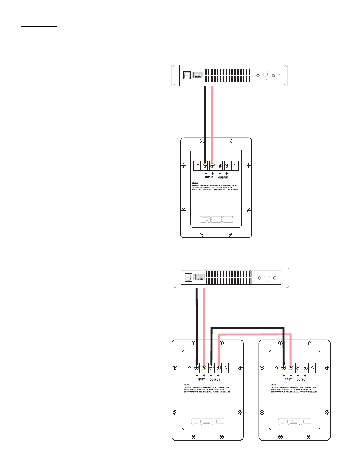
Connections
Normal Connection
The LF-3115 has barrier strip screw terminals for connection. The terminals accept
up to #10 AWG (5.3mm
speaker wiring. Use the largest wire size
and shortest wire length possible for a
given installation. Observe the polarity
markings and keep polarity consistent
throughout the system for best performance.
2
) stranded loud-
Normal Connection Example:
Amplifier capable of
driving 8 ohm loads
Parallel Connection of Second LF-3115
The terminals marked OUTPUT may be
used to connect another LF-3115 in parallel. Connect the wires as shown in the illustration, at right.
Parallel Connection Example:
Amplifier capable of
driving 4 ohm loads
LF-3115 Specifications (subject to change without notice)
Frequency Range: 33 - 1900 Hertz (-6dB)
30 - 3200 Hertz useable range (-10dB)
Nominal Coverage: 100° horizontal X 100° vertical at 1000 Hertz
Maximum Output:
Impedance: 8 ohms nominal
Maximum Input Power: 300 watts rms (8 hours of 6dB crest factor pink noise, 40 - 400 Hertz)
Sensitivity: 95.5dB half space, 94.0dB full space, 35 - 1000 Hertz, 1 watt, 1 meter
Recommended Processing: Subsonic filter below 30 Hertz, >18 dB per octave, maximum recommended crossover frequency is 1000 Hertz. QSC
Connectors: Barrier strip screw terminals accept up to #10 AWG (5.3mm
Transducers: 15” (381mm) high efficiency low frequency transducer featuring vented 3” (76mm) copper voice coil on Kapton® form-
126.5dB SPL calculated peak, 1 meter, half space, at rated rms power with 6 dB crest factor pink noise input, 35 - 1000 Hertz.
120.5dBA SPL calculated maximum continuous, 1 meter. The dBA scale is typically used to identify sound sources
which can cause permanent hearing loss.
8 ohms minimum, 160 Hertz
90 ohms maximum, 22 Hertz
375 watts rms (2 hours of 6dB crest factor pink noise, 40 - 400 Hertz)
Recommended amplifier power capability- 600 watts rms maximum into 8 ohms (per LF-3115)
DSP configurations are available at www.qscaudio.com. Parameters for alternative processing hardware are available
upon request.
2
) stranded wire. Four terminals: (two INPUT and two par-
allel OUTPUT).
ers. High excursion/low distortion design, with extremely high power handling, and low thermal and port compression.
Enclosure: Quasi B4 alignment, ported enclosure with fully flared ports, low turbulence symmetrical port design, tuned to 36
Hertz, constructed of medium density fibreboard and heavily braced. Features vandal resistant woofer mounting bolts.
Size: 30” wide X 18” high X 20” deep (762mm X 457mm X 508mm)
Weight: 96 lbs. shipping, 83 lbs. net (44/38 kg.)
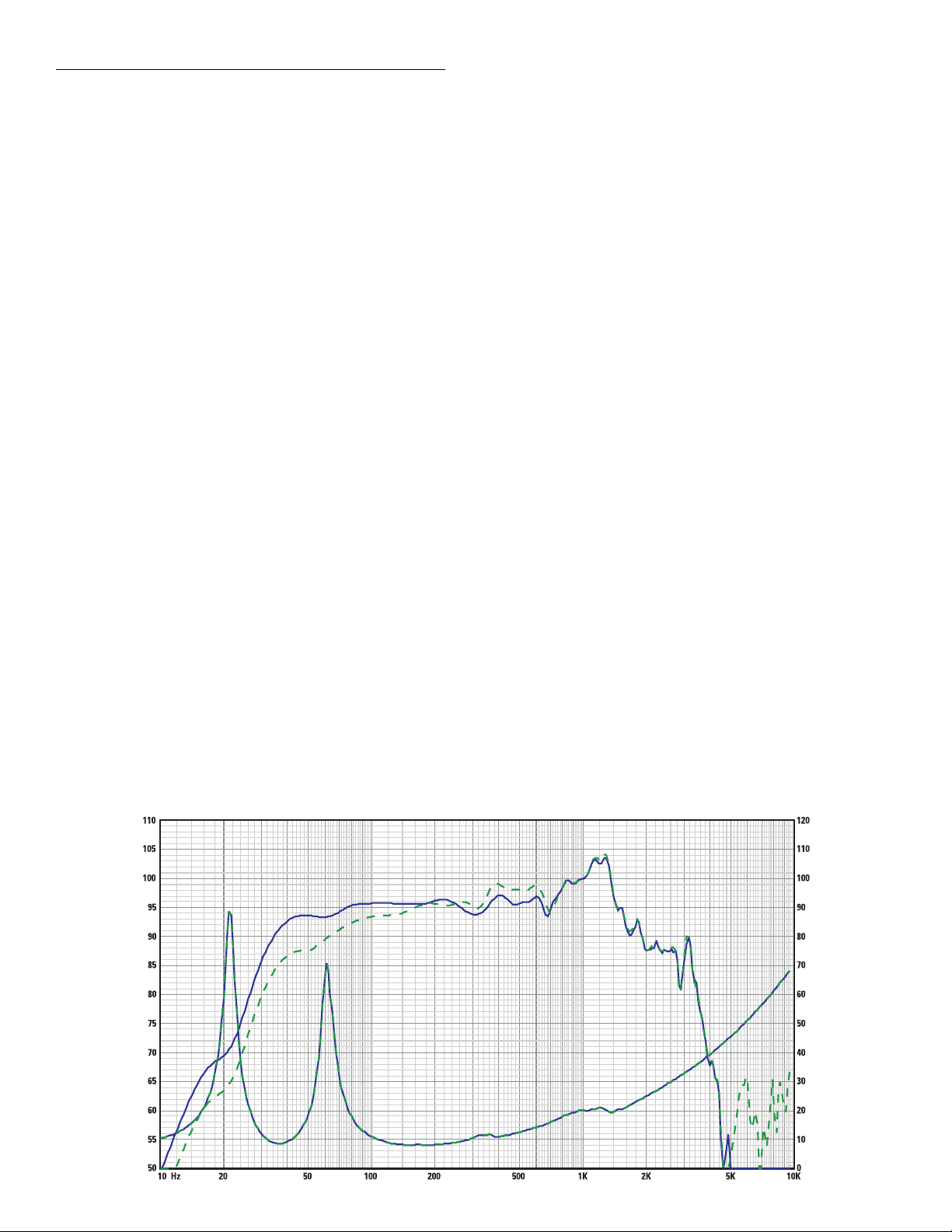
SPL and Impedance vs. Frequency
SPL 2pi
SPL 4pi
SPL (dB)
Impedance (ohms)
Impedance
Frequency (Hertz)

Warranty (USA only; other countries, see your dealer or distributor)
Disclaimer
QSC Audio Products, Inc. is not liable for any damage to amplifiers, or any other equipment that is caused by negligence or
improper installation and/or use of this loudspeaker product.
QSC Audio Products 3 Year Limited Warranty
QSC Audio Products, Inc. (“QSC”) guarantees its products to be free from defective material and / or workmanship for a period
of three (3) years from date of sale, and will replace defective parts and repair malfunctioning products under this warranty
when the defect occurs under normal installation and use - provided the unit is returned to our factory or one of our authorized
service stations via pre-paid transportation with a copy of proof of purchase (i.e., sales receipt). This warranty provides that
the examination of the return product must indicate, in our judgment, a manufacturing defect. This warranty does not extend
to any product which has been subjected to misuse, neglect, accident, improper installation, or where the date code has been
removed or defaced. QSC shall not be liable for incidental and/or consequential damages. This warranty gives you specific
legal rights. This limited warranty is freely transferable during the term of the warranty period.
Customer may have additional rights, which vary from state to state.
In the event that this product was manufactured for export and sale outside of the United States or its territories, then this limited warranty shall not apply. Removal of the serial number on this product, or purchase of this product from an unauthorized
dealer, will void this limited warranty. Periodically, this warranty is updated. To obtain the most recent version of QSC’s warranty statement, please visit www.qscaudio.com. Contact us at 800-854-4079 or visit our website at www.qscaudio.com.
Contacting QSC Audio Products
Mailing address:QSC Audio Products, Inc.
1675 MacArthur Boulevard
Costa Mesa, CA 92626-1468 USA
Telephone Numbers:
Main Number (714) 754-6175
Sales & Marketing (714) 957-7100 or toll free (USA only) (800) 854-4079
Customer Service(714) 957-7150 or toll free (USA only) (800) 772-2834
Facsimile Numbers:
Sales & Marketing Fax(714) 754-6174
Customer Service Fax(714) 754-6173
World Wide Web:www.qscaudio.com
E-mail:info@qscaudio.com
service@qscaudio.com
QSC Audio Products, Inc. 1675 MacArthur Boulevard Costa Mesa, California 92626 USA
©2004 “QSC” and the QSC logo are registered with the U.S. Patent and Trademark Office.
Kapton® is a registered trademark of E.I. du Pont de Nemours and Company.
1675 MacArthur Blvd., Costa Mesa, CA, 92626 EE.UU.
Número principal +1 (714) 754-6175 Ventas y Comercialización +1 (714) 957-7100
o línea sin costo (sólo para EE.UU.) +1 (800) 854-4079
Servicio al cliente +1 (714) 957-7150 o gratis (sólo EE.UU.) +1 (800) 772-2834
Manual del usuario de los sistemas de altavoces para salas
de cine
Componente de alta frecuencia HF-63
Introducción
El HF-63 es el componente de alta frecuencia de los sistemas del altavoz bidireccional de canal de pantalla biamplificada, para aplicaciones cinematográficas de
alto rendimiento. Fue diseñado para operar con, y montarse directamente en, el
woofer cinematográfico LF-3115 o LF-3215 de QSC.
El sistema HF-63 de alta frecuencia tiene un formato grande, un excitador de
compresión con diafragma de titanio de 2.5” (63.5 mm) montado en un cuerno
cinematográfico de alta frecuencia de diseño bajo especificaciones con un soporte de movimiento horizontal y vertical ajustable. El cuerno tiene amplios ángulos de cobertura horizontal y vertical para asegurar la cobertura de cada asiento
del auditorio. El cuerno es una guiaonda de baja deformación que proporciona
un diálogo altamente articulado sin la coloración asociada con los altavoces de
cuerno convencionales.
El HF-63 incluye protección del excitador y una red de ecualización para asegurar
una operación fiable. Los capacitores de bloqueo de CC protegen contra señales
de CC o de baja frecuencia que podrían destruir un excitador no protegido. El circuito limitador de potencia protege al excitador contra las sobrecargas, y un filtro de corrección de respuesta suaviza la respuesta de frecuencia de la
combinación cuerno/excitador. No obstante ello, se requiere el procesamiento
externo ya que el filtro de corrección de la respuesta no es de cruce.
Los componentes del sistema HF-63 vienen ya montados para reducir el tiempo
de montaje en el campo. Tres pernos es todo lo que se requiere para fijar el HF63 en la parte superior de una caja de baja frecuencia de QSC.
Montaje
Vea la información sobre el montaje en la ilustración. El HF-63 se conecta en la
parte superior del LF-3115 o LF-3215 con tres pernos de 5/16-18, de 0.75” de
largo, con arandelas de fijación. Este herraje se envía ya instalado en el gabinete del sistema de baja frecuencia. Recomendamos el uso de un compuesto
duradero para fijación de roscas al instalar los pernos para evitar que se aflojen
debido a la vibración. Oriente el cuerno en el plano horizontal antes de apretarlo.
Ajuste la posición vertical con el soporte de ajuste.
Instale de acuerdo con las instrucciones de QSC Audio Products
y de un ingeniero profesional con la debida licencia. Sólo use
piezas, montajes, accesorios o soportes especificados por QSC
Audio Products, Inc. Refiera todo el servicio a personal calificado. Cuando el aparato haya sido dañado de alguna manera, es
necesario proporcionarle servicio.
¡ADVERTENCIA! Antes de colocar, instalar, montar o suspender
cualquier producto de altavoz, inspeccione todo el equipo
físico, la suspensión, los armarios, los transductores, los soportes y el equipo asociado para detectar la existencia de daños.
Cualquier componente faltante, corroído, deformado, o sin
carga nominal podría reducir significativamente la resistencia
de la instalación, la colocación o la configuración. Cualquier
condición de este tipo reduce gravemente la seguridad de la
instalación y debe corregirse de inmediato. Use sólo herraje
que esté clasificado para las condiciones de carga de la instalación y cualquier posible carga excesiva a corto plazo inesperada. Nunca exceda el valor nominal del equipo físico ni del
dispositivo. Consulte a un ingeniero profesional con la debida
licencia cuando surjan dudas o preguntas referentes a la instalación física del equipo.
QSC® es una marca comercial registrada de QSC Audio Products, Inc.
“QSC” y el logotipo de QSC están registrados con la Oficina de Patentes y Marcas
© Derechos de autor 2004, QSC Audio Products, Inc.
Comerciales de los Estados Unidos
TD-000170-00 rev. C

Conexiones
Terminales de ENTRADA de HF
El HF-63 tiene terminales de tornillo de barra protectora que aceptan alambre trenzado de calibre de hasta #10 AWG (5.3 mm
altavoces. Conecte la señal de salida de alta frecuencia del amplificador en los terminales de ENTRADA de HF del altavoz. Observe la
polaridad adecuada; señal + del amplificador al altavoz + ENTRADA de HF, señal - del amplificador al altavoz - ENTRADA de HF. Use
el alambre de calibre más grande y de longitud más corta para la aplicación.
¡NOTA! Mantenga la polaridad adecuada en la conexión del altavoz en todo el sistema para obtener el máximo
rendimiento. ¡No aplique una señal de intervalo total al HF-63! No hay cruce en el HF-63, sólo una red de ecualización y protección. Todo el procesamiento requerido de la señal debe hacerse antes de aplicar la señal al HF-63.
Terminales de SALIDA de HF
Los terminales de SALIDA de HF se conectan en fábrica al excitador de compresión. Estos terminales SÓLO se deben conectar al excitador de compresión del HF-63.
DCM de QSC u otro
cruce activo
Amplificador
2
) para
Terminales de conexión del HF-63
Señal procesada
del programa de
alta frecuencia
Excitador de
compresión
Nota: ¡La caja de conexión del HF-63 no
contiene una red de cruce! Asegúrese que
sólo se aplique la señal de alta frecuencia
a los terminales de ENTRADA de HF,
porque de lo contrario, pueden ocurrir
daños al excitador de compresión.
Especificaciones del sistema HF-63 (sujetas a cambio sin previo aviso)
Intervalo de frecuencias: 400 – 16 kHz (-6 dB, espacio completo)
Cobertura nominal: 90° horizontal X +15° a -35° vertical (50° total), el montaje ajustable permite ajustes en el plano vertical.
El plano horizontal se puede ajustar alterando la posición de montaje de la caja del sistema de baja frecuencia antes de apretar los pernos.
DI: 9.0 dB (600 a 16,000 Hertzios como promedio)
Q: 8.0 (600 a 16,000 Hertzios como promedio)
Salida máxima: Pico calculado de SPL: 131.5 dB, 1 metro, medio espacio
Impedancia: 8 ohmios, nominal
9.0 ohmios como mínimo a 8,000 Hertzios
30 ohmios como máximo a 475 Hertzios
Potencia máxima 50 vatios rms (8 horas de ruido rosa con factor de cresta de 6 dB, 1,000 a 10,000 Hertzios)
de entrada: 60 vatios rms (2 horas de ruido rosa con factor de cresta de 6 dB, 1,000 -10,000 Hertzios, método AES)
Sensibilidad: 107.5 dB medio espacio, 1 vatio, 1 metro
Frecuencia de cruce: 1,000 Hertzios o más, 24 dB por octava
Conectores: Los terminales de tornillo de barra protectora aceptan alambre trenzado de hasta #10 AWG . Cuatro ter-
minales: (dos de ENTRADA de HF y dos de SALIDA de HF de post compensación). La SALIDA de HF se
conecta en fábrica al excitador de compresión.
Transductores: 1.5” (38 mm) salida, 2.5” (63.5 mm) excitador de compresión con diafragma de titanio
Herraje de montaje: Se conecta en la parte superior del gabinete del sistema de baja frecuencia mediante tres pernos de 5/
16”-18 x 3/4” de largo.
Tamaño : 30” de ancho X 16” de alto X 20” de profundidad (762 mm X 406 mm X 508 mm)
Peso: 50 libras (envío), 40 libras (neto, 22.7/18.4 kilogramos
SPL e impedancia en función de la frecuencia
SPL
SPL (dB)
Impedancia (ohmios)
Impedancia
Frecuencia (hertzios)
 Loading...