

Page 1

UF-3UF-3
UF-3
UF-3UF-3
UniversalUniversal
Universal
UniversalUniversal
FilterFilter
Filter
FilterFilter
*TD-004031-00*
Owner’s Manual
11
*TD-004031-00*
Rev. A
Page 2

Page 3
UF-3 UNIVERSAL FILTER
I. DESCRIPTION
The UF-3 is an embedded dual-channel universal filter accessory for use with select QSC power amplifiers. Compatible amplifier models and lines,
both current and discontinued, include:
• All PLX, two-channel CX, and two-channel DCA models (with a BSC-3 or BSC-5 BusCard installed)
• All four-channel CX and DCA models (with a BSC-7 BusCard installed)
• PowerLight models PL 1.0, PL 1.0HV, PL 1.4, PL 1.5X, PL 1.6
• PowerLight models PL 3.4, PL 3.8X, and PL 4.0 (with a BSC-6 BusCard installed)
HVX
, PL 1.8, and PL 2.0HV (with a BSC-2 or BSC-4 BusCard installed)
• All MXa models (MX 1000a, MX 1500a, MX 2000a, and MX 3000a;
Note: does not include MX 700
), which use Level 1 Open Input
Architecture
• All EX models (EX 800, EX 1250, EX 2500, and EX 4000), which use Level 2 Open Input Architecture
• Legacy CX models CX6, CX6T, CX12, and CX12T, which use Level 1 Open Input Architecture
Using the UF-3 as a default crossover or EQ is ideal for rental sound systems, since it virtually eliminates the possibility of unauthorized tampering
with settings or other such user errors.
Physically, the UF-3 is a small circuit card that mounts inside the amplifier. Older amplifier models that use Open Input Architecture have a twosection row of 22 solder holes called a “Mini Slot” on their input boards. This is where the UF-3 is installed. The input board is part of the
removeable input module, so the UF-3 can be installed without opening the amplifier chassis or even without removing the amplifier from an
equipment rack.
The UF-3 performs the same functions as the older UF-2 accessory does, but on a smaller, more compact circuit board that can fit in more amplifier
models, such as the PowerLight 3.4, 3.8X, or 4.0. To fit in these models, the circuit board has a pre-scored breakaway section.
Newer models such as the PowerLight, PLX, DCA and CX series require the installation of an appropriate BusCard in order to provide a slot for
the UF-3. Depending on the amplifier model, a BusCard can provide as many as four slots for accessory cards. Each slot is equivalent to the “Mini
Slot” of the older amplifiers’ Open Input Architecture. For ease of installation, it is best to mount the UF-3 to the BusCard before installing the
BusCard itself inside the amplifier.
The installation process involves soldering, so only qualified technical persons should attempt to install the UF-3; ideally, you should enlist QSC’s
Technical Services department or an authorized service center to perform the task. The installation section of this manual offers more information
about installing the UF-3.
II. FEATURES
The UF-3 allows independent filtering of the two audio channels. You can select high-pass, low-pass, or bandpass filtering, as well as the
frequencies of the filtering.
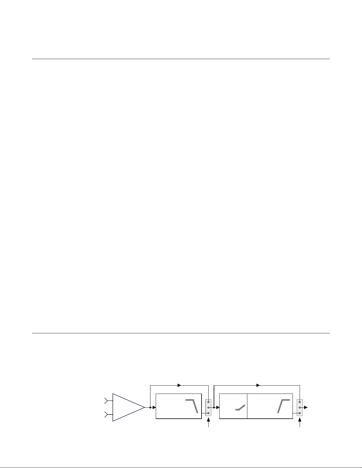
Either channel’s circuitry contains electronically balanced input circuitry and bypassable low-pass and high-pass circuitry. Each filter circuit has
a four-pole (24 dB/
octave) Linkwitz-Riley
alignment. Figure 1
shows a block diagram of the UF-3.
(+) Input
(-) Input
Figure 1—Block diagram of UF-3 (1 of 2 channels shown)
Input
Differential
Amplifier
Low-Pass Filter Bypass High-Pass Filter Bypass
Programmable
Linkwitz-Riley
Low-Pass Filter
1
2
3
3-pin
jumper block
Optional
CD Horn
Boost
Programmable
Linkwitz-Riley
High-Pass Filter
1
1
2
3
3-pin
jumper block
Channel
Output
Page 4
III. PROGRAMMING THE UF-3
RN102
( of low-pass filter)
f
RN104
( of high-pass filter)
f
RN204
( of low-pass filter)
f
RN202
( of high-pass filter)
f
(low-pass bypass/enable)
J101 J102
(high-pass bypass/enable)
J103
(CD horn EQ)
(low-pass bypass/enable)
J202 J201
(high-pass bypass/enable)
(CD horn EQ)
J203
1
2
3
1
2
3
1
2
3
1
2
3
Channel 1 Channel 2
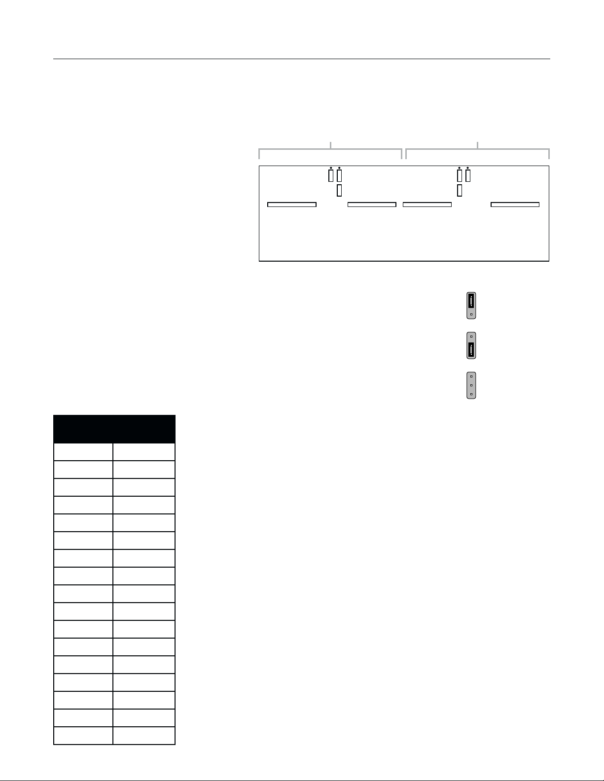
The UF-3 circuit board has six 3-pin headers and four SIP resistor network sockets (see Figure 2). All are used for programming the module. The
circuitry for the two channels is identical, so the headers and sockets are divided between them: those designated by a three-digit number starting
in a “1” (headers J101, J102, and J103; and SIP resistor network sockets RN102 and RN104) are for Channel 1, while those with a three-digit
number starting in a “2” are for Channel 2. The following instructions will use an “x” in place of the first digit, except where a specific channel
reference is necessary.
Notes on Stereo, Bridged, or Parallel
Operation
Except for specialized bi-amp models such as the
PowerLight 1.5X, 1.6
UF-3 is installed has a switch for setting the operating
mode of the amplifier, i.e., stereo, parallel mono, or
bridged mono. In the signal flow, the UF-3 accessory is
located after the switch, so you must configure both
channels of the UF-3 accordingly, whatever the operating
mode. Usually you would use identical settings on both
channels in stereo or parallel mode, depending on the application. If the amplifier is in bridged mode, bypass
Channel 2 of the UF-3 and use the Channel 1 input and processing only.
HVX
, or 3.8X, the amplifier in which the
Figure 2—UF-3 Circuit board jumper and resistor network locations
1
2
3
Pins 1 & 2
shorted together
Bypassing the Filtering
To completely bypass the filtering circuitry of a channel, set the jumpers on both Jx01 and Jx02 across pins 1 and
2, which are the upper two pins on their headers (see Figure 3). Note: If you neglect to place jumpers on either
header, no signal will pass on that channel.
ycneuqerF
)zH(
08K021
001K28
021K86
061K65
002K74
052K33
005K81
008K21
0001K2.8
0021K8.6
0061K6.5
rotsiserPIS
eulavkrowten
Programming the Low-Pass Filter
To use the low-pass filter, set the jumper on Jx01 across pins 2 and 3, which are the lower two pins on
their header. If, however, you do not wish to use the low-pass filter and want to bypass it instead, set the
jumper across pins 1 and 2.
To set the corner frequency (at which the output is 6 dB down) of the low-pass filter, choose the appropriate
value for RNx02; use the table at left.
If there is a resistor network already installed in the socket, carefully pull it straight out. Insert the pins
of the new resistor network into the socket holes and carefully press the network into the socket. Be
careful to avoid bending the pins of the resistor network. Orientation of the resistor network is
unimportant, as long as all eight pins are well seated in the socket.
1
Pins 2 & 3
2
shorted together
3
1
2
3
Figure 3—Jumper positions
0002K7.4
0052K3.3
0005K8.1
0008K2.1
00061065
00002074
2
Page 5

Programming the High-Pass Filter and CD Horn Equalization
To use either the high-pass filter or the constant-directivity horn equalization, or both, set the jumper on
Jx02 across pins 2 and 3, which are the lower two pins on their header. If, however, you do not wish to
use either one and want to bypass them instead, set the jumper across pins 1 and 2.
To set the corner frequency (at which the output is 6 dB down) of the high-pass filter, choose the
appropriate value for RNx04; use the table at right.
If there is a resistor network already installed in the socket, carefully pull it straight out. Insert the pins
of the new resistor network into the socket holes and carefully press the network into the socket. Be
careful to avoid bending the pins of the resistor network. Orientation of the resistor network is
unimportant, as long as all eight pins are well seated in the socket.
ycneuqerF
)zH(
02K021
03K28
04K65
05K74
08K72
001K22
021K02
rotsiserPIS
eulavkrowten
In addition to enabling the high-pass filter at Jx02, if you opt for CD horn equalization you must place a
jumper at Jx03 as well. The UF-3 offers two equalization curves for CD horn correction: one with +6 dB
of boost at 20 kHz (place the jumper across pins 1 and 2 of Jx03), and one with +10 dB of boost at 20 kHz
(place the jumper across pins 2 and 3). If you do not place a jumper in one position or the other, the CD
horn equalization circuit will be inactive.
The table below is a summary of jumper settings for the UF-3; similar information is printed on the
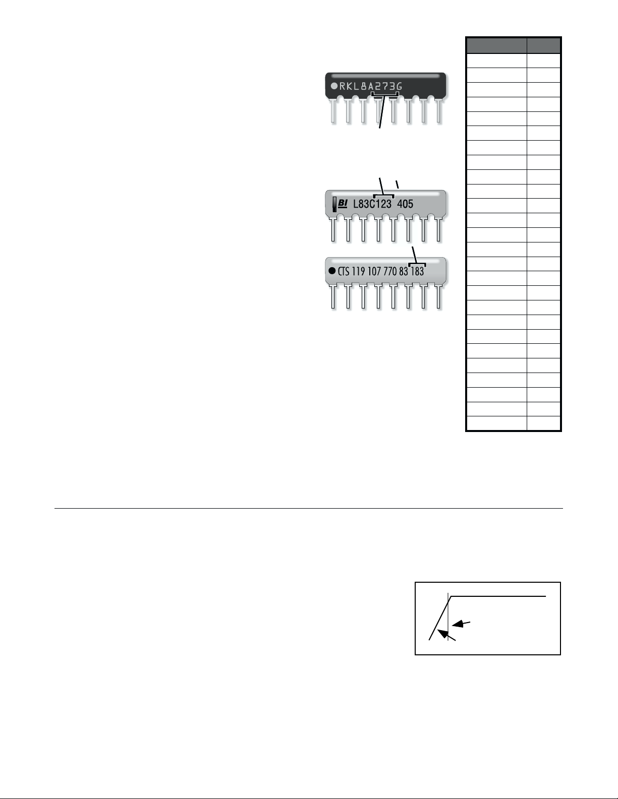
breakaway section of the UF-3’s circuit board. Figure 4 shows how to identify the SIP resistor values.
2&1sniP3&2sniPenoN
noitcnuFredaeH
ssap-wolssapyB101JX
ssap-wolelbanE101JX
ssap-hgihssapyB201JX
:1lennahC
:2lennahC
ssap-hgihelbanE201JX
tsoobnrohDCelbasiD301JX
zHk02@Bd6+,tsoobnrohDC301JX
zHk02@Bd01+,tsoobnrohDC301JX
ssap-wolssapyB102JX
ssap-wolelbanE102JX
ssap-hgihssapyB202JX
ssap-hgihelbanE202JX
tsoobnrohDCelbasiD302JX
zHk02@Bd6+,tsoobnrohDC302JX
zHk02@Bd01+,tsoobnrohDC302JX
051K51
002K21
003K2.8
004K6.5
005K7.4
008K7.2
0001K2.2
0021K0.2
0051K5.1
0002K2.1
0004065
0005074
0008072
3
Page 6
Use only these three digits to
determine resistance code.
Disregard the other
numerals and letters.
Figure 4—SIP resistor network
identification
RESISTANCE
270
470
560
1.2K
1.5K
1.8K
2.0K
2.2K
2.7K
3.3K
4.7K
5.6K
6.8K
8.2K
12K
15K
18K
20K
22K
27K
33K
47K
56K
68K
82K
120K
CODE
271
471
561
122
152
182
202
222
272
332
472
562
682
822
123
153
183
203
223
273
333
473
563
683
823
124
IV. TYPICAL APPLICATIONS
Subsonic Filter
Subsonic filters are commonly used in sound installations to filter out rumbles and other inaudible or unwanted low frequency signals and to
protect speaker drivers. Vented speaker enclosures in particular often exhibit a phenomenon in which the acoustical damping on the driver(s)
drops at extremely low frequencies below their own resonant frequency. In a situation like this, a
subsonic filter will help to prevent damage from over-excursion of the speaker cone.
Program settings:
1. Set the jumper on Jx01 to bypass the low-pass filter (across pins 1 and 2).
2. Set the jumper on Jx02 to enable the high-pass filter (across pins 2 and 3).
3. No jumper on Jx03.
4. Insert a resistor network in RNx04 that is appropriate to the desired roll-off frequency—typically 20, 30, 40, or 50 Hz.
4
Figure 5—UF-3 as a subsonic filter
Typ. 20–50 Hz
Subsonic roll-off
Page 7
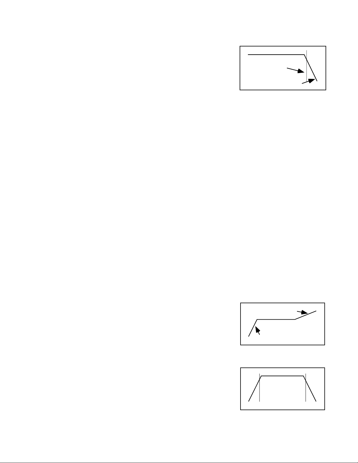
Ultrasonic Filter
Typ. 16–20 kHz
Ultrasonic roll-off
An ultrasonic filter is useful for minimizing RF interference, oscillations, leakage or aliasing from digital devices, and other signals that are too
high in pitch to hear but may wreak havoc in an amplifier system.
Program settings:
1. Set the jumper on Jx01 to enable the low-pass filter (across pins 2 and 3).
2. Set the jumper on Jx02 to bypass the high-pass filter (across pins 1 and 2).
3. Insert a resistor network in RNx02 that is appropriate to the desired roll-off frequency—
typically 16 or 20 kHz.
Figure 6—UF-2 as an ultrasonic filter
Bandpass Filter
A bandpass filter may be useful if the speaker system driven by the amplifier has a limited bandwidth. Minimizing the out-of-the-passband energy
may result in reduced distortion and better intelligibility.
Program settings:
1. Set the jumper on Jx01 to enable the low-pass filter (across pins 2 and 3).
2. Set the jumper on Jx02 to enable the high-pass filter (across pins 2 and 3).
3. No jumper on Jx03.
4. Insert a resistor network in RNx04 that corresponds to the lower limit of the desired frequency passband.
5. Insert a resistor network in RNx02 that corresponds to the upper limit of the desired frequency passband. This frequency must be higher
than the one selected for the previous step.
CD Horn Equalization Filter
A constant-directivity horn requires a 6 dB per octave high-frequency boost from about 3.5 kHz to provide a flat frequency response. On the UF-3
you must use the CD horn equalization in conjunction with the high-pass filter.
Program settings:
1. Set the jumper on Jx01 to bypass the low-pass filter (across pins 1 and 2).
2. Set the jumper on Jx02 to enable the high-pass filter (across pins 2 and 3).
3. Set the jumper on Jx03 to select the EQ curve you desire: across pins 1 and 2 for +6 dB at 20 kHz, or across pins 2 and 3 for +10 dB at 20 kHz.
4. Insert a resistor network in RNx04 that corresponds to the desired low-frequency roll-off.
Subsonic Filter with CD Horn EQ
Use settings 1, 2, and 4 from the Subsonic Filter, and setting 3 from the CD Horn Equalization Filter.
This would be suitable only if the loudspeaker system uses passive crossovers.
Figure 7—UF-2 as a subsonic filter with CD
horn EQ
CD Horn boost
Subsonic roll-off
Subsonic and Ultrasonic Filter
Use settings 2, 3, and 4 from the Subsonic Filter along with 2 and 3 from the Ultrasonic filter.
5
Typ. 16–
Typ.
20–50 Hz
Figure 8—UF-2 as a subsonic and ultrasonic
filter
20 kHz
Page 8
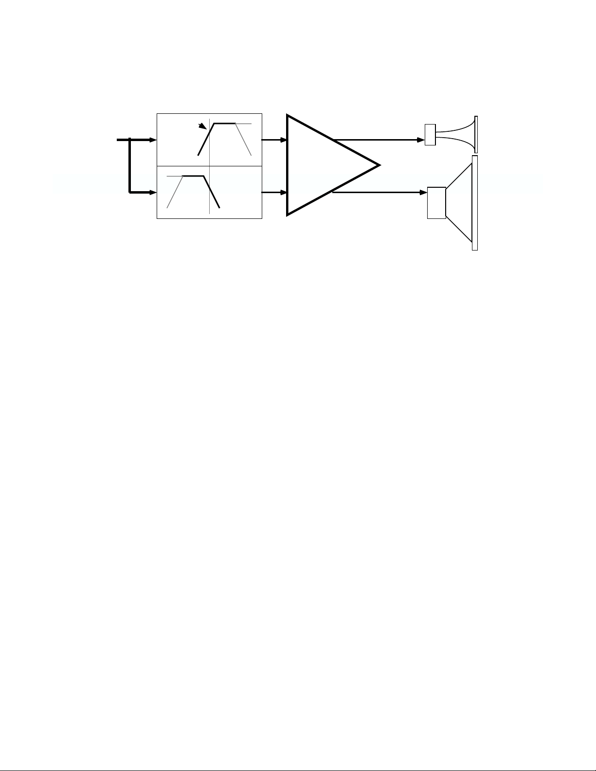
2-Way Active Crossover
This configuration routes the frequencies below a particular frequency to amplifier Channel 1, which shall drive the low-frequency speakers, and
the frequencies above to Channel 2, which shall drive the high-frequency speakers. Using the UF-3 as a crossover requires that you drive both
amplifier inputs with the same full-band signal.
HF Driver
F
c
Channel 2
Channel 2
Channel 1
SPA-2
Figure 9—UF-2 as a 2-way active crossover
Amp
Channel 1
LF Driver
Program settings:
1. On the input module, set the amplifier mode to parallel. Alternately, you could use a Y-cable to provide the same signal to both channel
inputs.
Steps 2 through 5 configure Channel 1.
2. Jumper J101 to enable Channel 1’s low-pass filter (across pins 2 and 3).
3. No jumper on J103.
4. Insert a resistor network into RN102 that is appropriate to the desired crossover frequency.
5. If you need subsonic filtering, set a jumper on J102 to enable Channel 1’s high-pass filter (across pins 2 and 3) and insert a resistor
network into RN104 that corresponds to the roll-off frequency you desire. If you do not want subsonic filtering, set J102 to bypass the
high-pass filter (across pins 1 and 2).
Steps 6 through 9 configure Channel 2.
6. Set J202 to enable Channel 2’s high-pass filter.
7. Insert a resistor network into RN204 that is appropriate to the crossover frequency you set in #4.
8. If you need equalization for a constant-directivity horn, set a jumper on J203 for the amount of boost you need. If you do not want CD
horn equalization, do not place any jumper on J203.
9. If you need ultrasonic filtering, set a jumper on J201 to enable Channel 2’s low-pass filter (across pins 2 and 3) and insert a resistor
network into RN202 that corresponds to the desired roll-off frequency. If you do not want any ultrasonic filtering, set the jumper on
J201 to bypass the low-pass filter (across pins 1 and 2).
6
Page 9
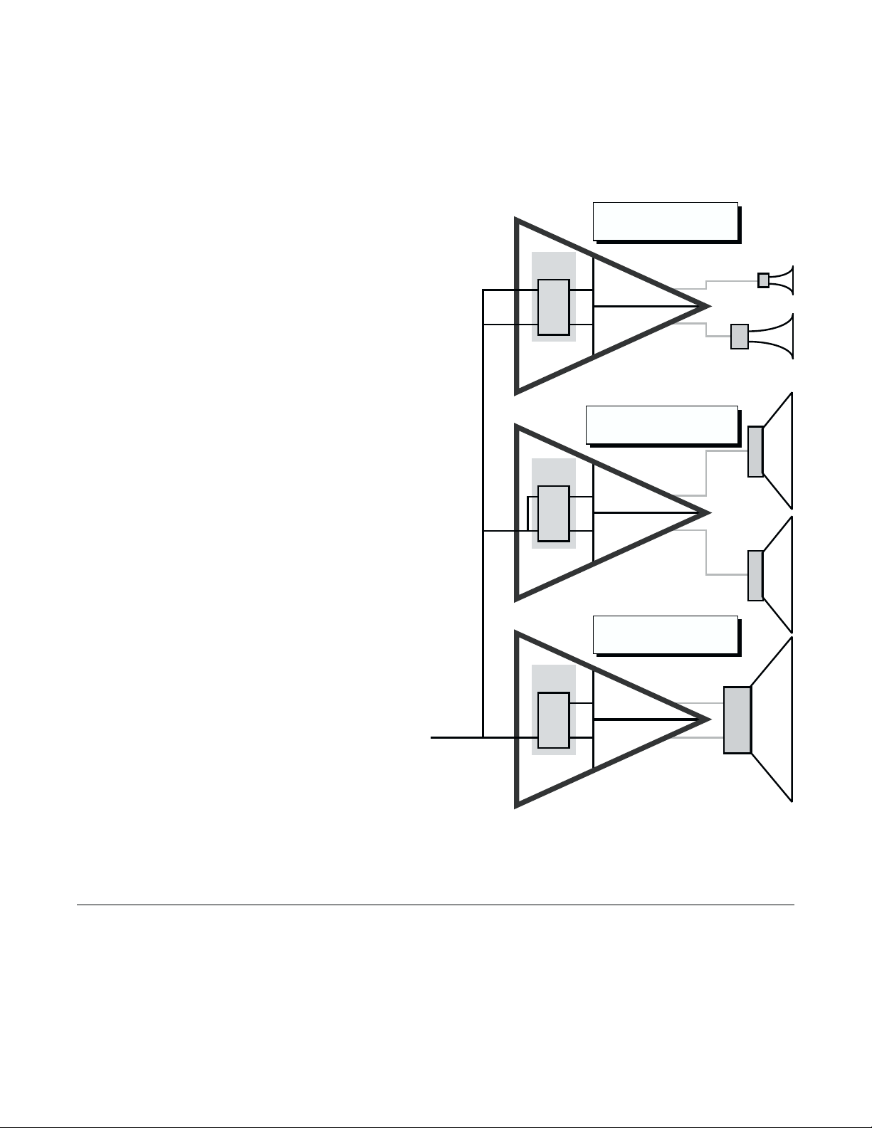
Multi-way Crossover System
The UF-3 allows you to set up 3- and even 4-way systems. Of course, this also requires that you use more than one amplifier and more than one
UF-3. The other basic requirement of using the UF-3 as a crossover is that you must feed each amplifier with the same full-range signal and use
the UF-3 to filter the signals in the individual channels.
Figure 9 depicts an example of a 4-way system. Because of the multitude of possible system configurations, the fundamentals of the technique
used in the example will be explained below, with a few specifics. The actual crossover frequencies you should use will depend on your
speaker system.
UF-3: Mids & Highs
Ch. 1:
Subwoofer
The subwoofer subsystem in the example is driven by a bridged
amplifier. Channel 1 of the UF-3 in this amplifier is set with the highpass filter at 20 Hz (for subsonic filtering) and the low-pass at 150 Hz,
which is the crossover point to the woofers. Channel 2 of the UF-3 is
bypassed.
BSC-2
BusCard
UF-3
LP @ 5 kHz; HP @ 1000 Hz
Ch. 2
LP @ 20 kHz; HP @ 5 kHz
Ch. 2
Ch. 1
Woofer
The woofers are driven by an amplifier operating in the parallel
mode. Both channels of its UF-3 are set with the high-pass filter at
150 Hz (the crossover point from the subwoofers) and the low-pass
filter at 1 kHz.
Midrange and High Frequencies
The remaining speakers are driven by the same amplifier: the mids
by channel 1, and the highs by channel 2. The settings for channel 1
of the UF-3 are: high-pass at 1 kHz (the crossover from the woofers)
and low-pass at 5 kHz (the crossover point to the high-frequency
drivers).
Channel 2 of the UF-3 is set for high-pass at 5 kHz. For ultrasonic
protection, the low-pass is set at 20 kHz.
BSC-6
BusCard
UF-3
BSC-6
BusCard
UF-3
PowerLight 1.6
UF-3: Woofers
Ch. 1:
LP @ 1000 Hz; HP @ 150 Hz
Ch. 2
LP @ 1000 Hz; HP @ 150 Hz
Ch. 2
Ch. 1
PowerLight 3.4
(parallel mode)
UF-3: Subwoofer
Ch. 1:
LP @ 150 Hz; HP @ 20 Hz
Ch. 2
Bypassed
Ch. 2
Ch. 1
HVX
PowerLight 4.0
(bridged mode)
Figure 10—Multiple amplifiers with UF-3s, set up for 4-way crossover
operation
V. INSTALLATION
Installating the UF-3 requires PC board soldering skills, so only qualified service technicians should attempt it. Any authorized QSC service
center—or, for an additional installation fee, QSC Technical Services Group—can perform the installation.
The UF-3 installs on a BusCard, which mounts inside the amplifier. Make sure you have the right BusCard for the amplifier model.
The UF-3 also installs on the amplifier input PC board of any QSC EX, MXa, or legacy CX Series amplifier. Some older EX amplifiers may require
an upgrade to the current input board. Contact the QSC Technical Services Group for details on compatibility with older EX amplifiers.
When installed, the UF-3 settings and adjustments are not externally adjustable; this can prevent tampering by unauthorized users.
7
Page 10
Tools and materials you will need:
Soldering iron
Desoldering iron or other suitable desoldering equipment
Phillips screwdriver
Wire cutters
Rosin-core solder
CAUTION:
• Do not use desoldering braid because it may damage the solder pads on the BusCard or input board, and it also might not adequately
remove solder.
• The UF-3 contains active components which can be damaged by electrostatic discharge (ESD). Be sure to practice standard ESD
precautions and always ground yourself and your workstation before handling exposed circuit cards.
• Preparing the input board for installation of the UF-3 involves removing solder from feed-through holes on a two-sided circuit card.
Excessive heat can easily damage the solder pads you will be working on. Proper equipment and experience with desoldering delicate
PC board circuitry is essential to successfully perform the following procedure.
• Please contact the QSC Technical Services Group if you feel you might not be qualified to perform the installation yourself.
•
One last warning:
damage caused by an improper installation will void the warranty.
Installing the UF-3 on a BusCard
It is easier to configure and install the UF-3 Universal Filter with the BusCard removed from (or not yet installed in) the amplifier.
Turn off the amplifier and unplug it from the AC. Allow about 10 minutes or longer for the internal voltages to bleed down before you open the
amplifier chassis.
If the UF-3 is to be installed on a BSC-6 BusCard (for the PowerLight 3.4, 3.8X, or 4.0), snap off the breakaway section of the UF-3 circuit board
by flexing it at the pre-scored line.
Make sure you insert the UF-3 card on the correct side of the BusCard. Insert the UF-3 fully into the holes on the BusCard. Solder all 22 pins to
the BusCard; make sure you don’t create any solder bridges. Then install the BusCard in the amplifier; see the BusCard instructions for details.
Installing the UF-3 on an input card
Turn off the amplifier and unplug it from the AC. Allow about 10 minutes or longer for the internal voltages to bleed down before you open the
amplifier chassis. Disconnect all cables from the amplifier’s input panel.
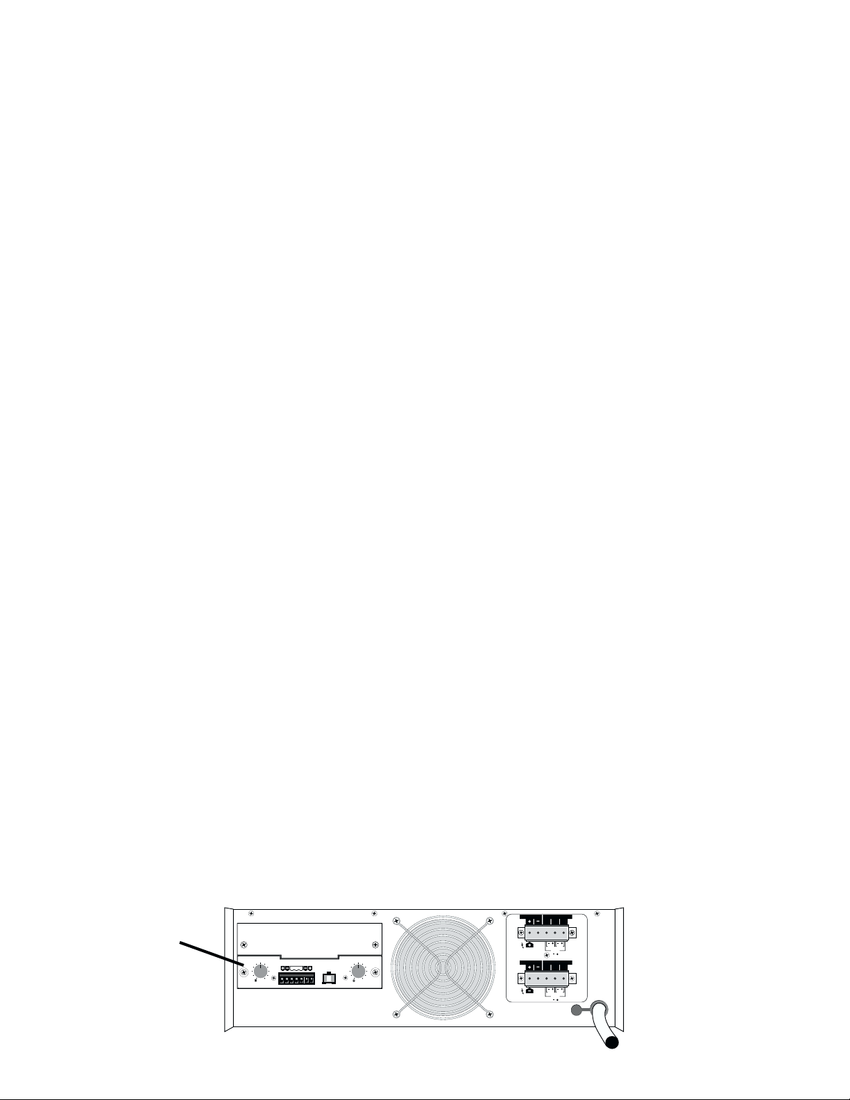
Position the amplifier so the rear of the chassis is facing you. The input panel is located on the left side of the rear panel. See Figure 11.
Begin the installation by locating and removing the screws securing both the upper blank and lower input panels to the rear side of the chassis
(two screws on each mini panel). The upper blank panel will simply drop off when its screws are removed.
Gently pull the lower input panel out from the amplifier. Once it is removed, you will notice a ribbon cable connecting the input PC board to the
amplifier. Disengage the locking wing clamps on the ribbon header and carefully remove the ribbon head from the socket on the board. Now the
input panel assembly is completely free from the amplifier.
Next, desolder and remove the wire jumper pairs W305/W306 and W405/W406 (W303/W304 and W403/W404 on MXa Series amplifiers).
Under where the jumpers were are two rows of solder pad holes, one with 10 holes and another with 12. These make up the “Mini-Slot,” in which
the UF-3 mounts. See Figure 12.
Input card
CH2 C H1
10 10
88
12
CH2 INPUT CH1
66
14
18 18
24
GROUND
44
22
0
-dB -dB
INPUT
12
14
STEREO
24
PARALLEL BRIDGE LEVELLEVEL
0
Figure 11—Location of the input card
LOW IMPEDANCE
AUDIO TRANSFORMER
CH1
DIR. OUTPUT
CH2
DIR. OUTPUT
BRIDGE
MONO
LOW IMPEDANCE
BRIDGE
MONO
070100
70V
25V
100V
AUDIO TRANSFORMER
070100
70V
25V
100V
ISOL.OUTPUT
ISOL.OUTPUT
CH1
CH2
8
Page 11
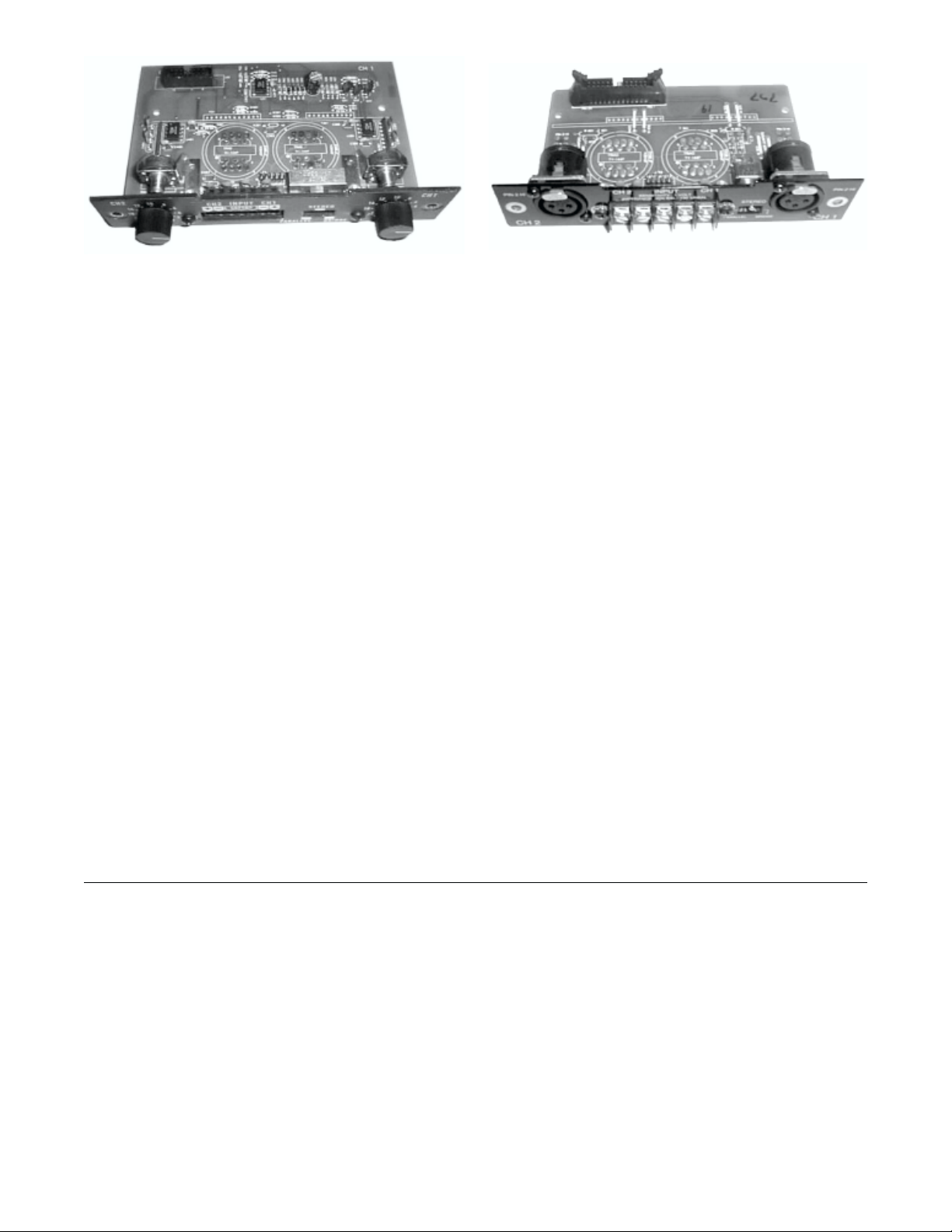
Figure 12—The legacy CX (left) and EX Series (right) input cards
Continue preparing the PC board by removing solder from all 22 in-line socket holes. Once this is done, you are ready to install the UF-3.
With the input panel facing you and the component side of the UF-3 board facing away from you, carefully insert the header pins of the UF-3 fully
into the socket holes. Turn the assembly over and solder the UF-3 in place. Make sure all the header pins are well soldered. Visually inspect for
cold solder joints and verify that you have sufficient clearance to re-install the ribbon connector on the top side of the assembly. Finish by trimming
the UF-3 header pins as required.
Reconnect the ribbon cable to the input board connector. Press the locking clamp wings of the connector closed. You will feel them snap onto
place.
If you need to make any adjustments to the UF-3 settings or if you need to record them, do so now, because the UF-3 will be inaccessible once
the input panel is re-installed into the amplifier chassis.
Carefully reposition the input board/UF-3 assembly into the amplifier chassis and secure it by fastening the two mounting screws. Make sure
the screws are tightened snugly, but do not over-torque them. Re-install the upper blank panel.
Installation of the UF-3 is now complete, and the amplifier is ready to be reinstalled into the system.
VI. WARRANTY AND DISCLAIMERS
Disclaimer
QSC Audio Products, Inc. is not liable for any damage to speakers, amplifiers, or any other equipment that is caused by negligence or improper
installation and/or use of the UF-3.
Product Warranty
QSC Audio Products, Inc. guarantees the UF-3 to be free from defective material and/or workmanship for a period of three years from date of
sale, and will replace defective parts and repair malfunctioning products under this warranty when the defect occurs under normal installation
and use—provided the unit is returned to our factory via prepaid transportation with proof of purchase (sales receipt). This warranty provides
that examination of the returned product must disclose, in our judgment, a manufacturing defect. This warranty does not extend to any product
which has been subject to misuse, neglect, accident, improper installation, or on which the date code has been removed or defaced.
9
Page 12

VII. TECHNICAL ASSISTANCE & SERVICE
Servicing your QSC product requires a trained and qualified technician. There are no user serviceable components inside, and the danger of
electric shock exists. Additionally, some of the components are QSC-specific parts that require QSC replacements. Comprehensive service
manuals for most models are available from QSC.
Technical Assistance
If you suspect that your UF-3 is defective, check your system configuration and UF-3 settings to determine the origin of the problem. Incorrect
audio interfacing, poor cabling, or other system-level impairments are the leading causes of problems in audio systems. For technical assistance
beyond the information given in this manual, contact QSC Technical Services.
Factory Service
If your UF-3 needs factory service, contact QSC Technical Services for instructions and a Return Authorization (RA) number. QSC cannot be held
responsible for products that are returned without a Return Authorization.
Product Return Guidelines
1. Pack the product well for protection during shipment. QSC will provide factory packaging upon request, free of charge.
2. Include a copy of the sales receipt, your name, return address, phone number, and defect description with your return correspondence.
3. Call or e-mail QSC Technical Services for a Return Authorization number. Have the product’s model number and serial number, as well
as your shipping and telephone information ready at hand.
4. Mark the Return Authorization number on the outside of the packaging.
5. Ship the product prepaid to QSC Audio Products. We recommend United Parcel Service (UPS).
QSC Technical Services
1665 MacArthur Blvd.
Costa Mesa, CA 92626 USA
Telephone: +1 (800) 772-2834
+1 (714) 957-7150
+1 (714) 754-6175
Fax: +1 (714) 754-6173
Qualified Service Centers
QSC maintains a service center network for your convenience. If you wish to return your product to a local service center, call QSC Technical
Services for a referral. However, accessories, input modules, and other peripheral QSC products must be returned to the factory for service.
International Servicing
For QSC products outside the United States, contact the distributor or dealer from where the product was purchased. There are numerous service
centers in many countries. You can get a referral to a service center in your country from your dealeror distributor, or by contacting QSC Technical
Services.
10
Page 13

Page 14

QSC Audio Products, Inc. 1675 MacArthur Blvd., Costa Mesa, California 92626 USA Tel: +1 714 754-6175 Fax: +1 714 754-6174 Web: www.qscaudio.com
12
 Loading...