

Page 1
™
Hardware User Manual
PS-X – Page Station Expander
TD-000356-00-A
*TD-000356-00*
Page 2
EN
EXPLANATION OF TERMS AND SYMBOLS
The term “WARNING!” indicates instructions regarding personal safety. If the instructions are not followed the result may be bodily injury or death.
The term “CAUTION!” indicates instructions regarding possible damage to physical equipment. If these instructions are not followed, it may result in
damage to the equipment that may not be covered under the warranty.
The term “IMPORTANT!” indicates instructions or information that are vital to the successful completion of the procedure.
The term "NOTE" is used to indicate additional useful information.
The intent of the lightning fl ash with arrowhead symbol in a triangle is to alert the user to the presence of un-insulated "dangerous"
voltage within the product's enclosure that may be of suffi cient magnitude to constitute a risk of electric shock to humans.
The intent of the exclamation point within an equilateral triangle is to alert the user to the presence of important safety, and operating
and maintenance instructions in this manual.
IMPORTANT SAFETY INSTRUCTIONS
WARNING!: TO PREVENT FIRE OR ELECTRIC SHOCK, DO NOT EXPOSE THIS EQUIPMENT TO RAIN OR MOISTURE.
– Maximum operating ambient temperature is 50°C (122°F).
• Read these instructions.
• Keep these instructions.
• Heed all warnings.
• Follow all instructions.
• Do not use this apparatus near water.
• Clean only with a dry cloth.
• Do not block any ventilation opening. Install in accordance with the manufacturer's instructions.
• Do not install near any heat sources such as radiators, heat registers, stoves, or other apparatus (including amplifi ers) that produce heat.
• Only use attachments/accessories specifi ed by the manufacturer.
• Unplug this apparatus during lightning storms or when unused for long periods of time.
• Refer all servicing to qualifi ed service personnel. Servicing is required when the apparatus has been damaged in any way, such as power-supply
cord or plug is damaged, liquid has been spilled or objects have fallen into the apparatus, the apparatus has been exposed to rain or moisture,
does not operate normally, or has been dropped.
• Adhere to all applicable, local codes.
• Consult a licensed, professional engineer when any doubt or questions arise regarding a physical equipment installation.
Designed and Assembled in the USA
2
Page 3

FCC Statement
NOTE: This equipment has been tested and found to comply with the limits for a Class B digital device, pursuant to Part 15 of the
FCC Rules.
These limits are designed to provide reasonable protection against harmful interference in a residential installation. This equipment generates, uses
and can radiate radio frequency energy and, if not installed and used in accordance with the instructions, may cause harmful interference to radio
communications. However, there is no guarantee that interference will not occur in a particular installation. If this equipment does cause harmful
interference to radio or television reception, which can be determined by turning the equipment off and on, the user is encouraged to try to correct
the interference by one or more of the following measures:
• Reorient or relocate the receiving antenna.
• Increase the separation between the equipment and receiver.
• Connect the equipment into an outlet on a circuit different from that to which the receiver is connected.
• Consult the dealer or an experienced radio/TV technician for help.
Warranty (USA only; other countries, see your dealer or distributor)
QSC Audio Products 3 Year Limited Warranty
QSC Audio Products, LLC (”QSC”) guarantees its products to be free from defective material and/or workmanship and will replace defective parts
and repair malfunctioning products under this warranty when the defect occurs under normal installation and use, provided the unit is returned to
our factory, one of our authorized service stations or an authorized QSC International Distributor via pre-paid transportation with a copy of proof
of purchase (i.e., sales receipt). This warranty provides that the examination of the return product must indicate, in our judgment, a manufacturing
defect. This warranty does not extend to any product which has been subjected to misuse, neglect, accident, improper installation, or where the
date code has been removed or defaced. QSC shall not be liable for incidental and/or consequential damages. This warranty gives you specifi c legal
rights. This limited warranty is freely transferable during the term of the warranty period. The warranty on QSC products is NOT VALID if the products
have been purchased from an unauthorized dealer/online e-tailer, or if the original factory serial number has been removed, defaced, or replaced in
any way. Damage to, or loss of any software or data residing on the product is not covered. When providing repair or replacement service, QSC will
use reasonable efforts to reinstall the product’s original software confi guration and subsequent update releases, but will not provide any recovery or
transfer of software or data contained on the serviced unit not originally included in the product.
EN
Customers may have additional rights, which vary from state to state or from country to country. In the event that a provision of this limited warranty is
void, prohibited or superseded by local laws, the remaining provisions shall remain in effect.
The QSC limited warranty is valid for a period of three (3) years from date of purchase in the United States and many (but not all)
other countries.
For QSC warranty information in countries other than the United States, contact your authorized QSC international distributor. A list of QSC
International distributors is available at www.qscaudio.com.
To register your QSC product online, go to www.qscaudio.com and select ”Product Registration”. Other questions regarding this warranty can be
answered by calling, e-mailing or contacting your authorized QSC distributor.
Phone: 1-800-854-4079 within US and Canada, +1-714-754-6175 international, Email: warranty@qscaudio.com, Website: www.qscaudio.com.
3
Page 4
RoHS STATEMENT
The Q-Sys PS-X products are in compliance with European Directive 2002/95/EC – Restriction of Hazardous Substances (RoHS).
The Q-Sys PS-X products are in compliance with “China RoHS” directives. The following chart is provided for product use in China and its territories:
Q-Sys PS-X
部件名称
(Part Name)
铅
(Pb)
电路板组件
(PCB Assemblies)
机壳装配件
(Chassis Assemblies)
O: 表明这些有毒或有害物质在部件使用的同类材料中的含量是在 SJ/T11363_2006 极限的要求之下。
(O: Indicates that this toxic or hazardous substance contained in all of the homogeneous materials for this part is below the limit requirement
in SJ/T11363_2006.)
XOOO O O
XOOO O O
汞
(Hg)
(Toxic or hazardous Substances and Elements)
有毒有害物质或元素
镉
(Cd)
六价铬
(Cr(vi))
多溴联苯
(PBB)
多溴二苯醚
(PBDE)
EN
X: 表明这些有毒或有害物质在部件使用的同类材料中至少有一种含量是在 SJ/T11363_2006 极限的要求之上。
(X: Indicates that this toxic or hazardous substance contained in at least one of the homogeneous materials used for this part is above the
limit requirement in SJ/T11363_2006.)
4
Page 5
Introduction
The Page Station Expander is designed to be mounted on a wall housed in a standard, US 2-gang, electrical wall box and connects directly to the
rear of a Q-Sys Page Station via Cat 5e cable. Voice input is provided through a handheld dynamic push-to-talk microphone. A unique magnetic
docking system and cable strain relief allow fl exibility in microphone placement when not in use, yet help deter theft or removal of the microphone.
Combining the Page Station Expander and the Page Station provide multiple inputs for a common zone, for example both the kiosk and jet-way of an
airport gate can easily be served by this combination.
For detailed information about the Q-Sys Page Stations, and the Q-LAN Network, refer to the Page Station User Guide, and the Q-Sys Designer
online help.
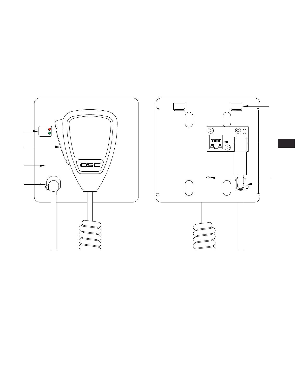
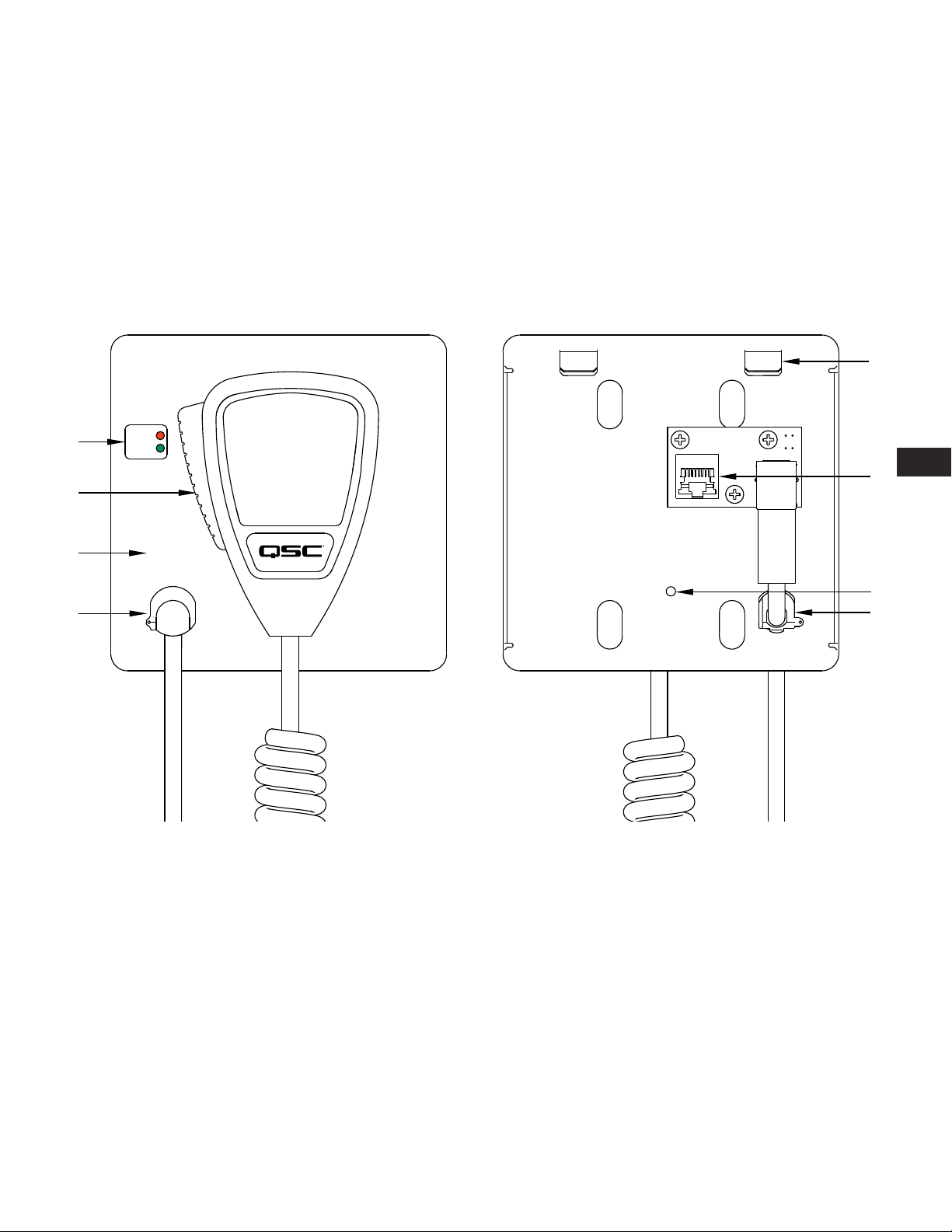
Page Station Expander Features
1
1
2
3
4
BUSY
READY
1. Busy and Ready LED
indicators
2. Push-to-talk button
— Figure 1 —
3. Magnetic Surface
4. Locking Strain Relief
2
EN
3
4
1. Mounting Tabs
2. RJ-45 Connector (to Page
— Figure 2 —
3. Mounting Screw hole
4. Locking Strain Relief
Station)
5
Page 6
The Q-Sys Q-LAN Network
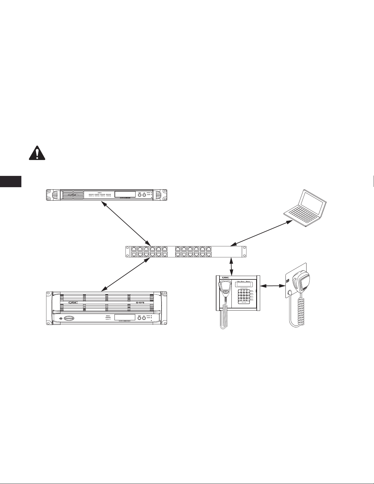
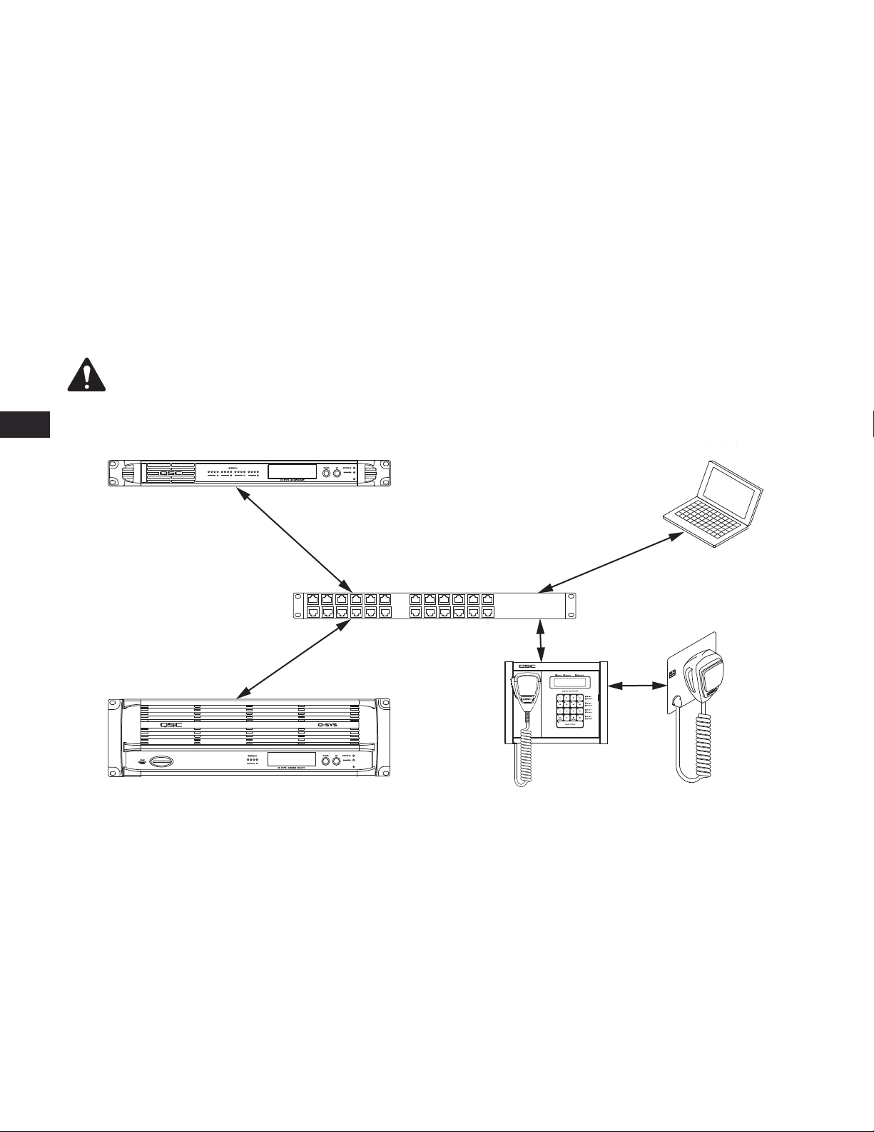
The Q-Sys solution (Figure 3) is designed to be deployed on QSC’s high performance Q-LAN network. Q-LAN is a proprietary network
implementation that bundles several industry standard protocols into a data transport solution appropriate for live performance multimedia
environments. Q-LAN offers gigabit data rates, device and network redundancy, 32-bit fl oating point audio data transfers, and low-latency support on
local area network deployments. Accurate synchronization of end nodes and high-quality clock distribution are built into the Q-LAN solution using
the IEEE-1588 Precision Time Protocol. Discovery of end nodes and auto-confi guration of end nodes are all included in the solution using industry
standard protocols over a standards-based IP network implementation using off-the-shelf hardware components.
Figure 3 shows a very simple Q-LAN network implementation with a Q-Sys Core Processor, a Q-Sys I/O Frame, a Q-Sys PS-X Page Station Expander,
Ethernet switch, and a PC running Q-Sys Designer.
All devices are connected to a managed 1000 Mbps Ethernet switch that includes the appropriate QoS, (Quality of Service) suitable for a
high-performance gigabit network to support multimedia applications.
The PS-X is confi gured via Q-Sys Designer when you confi gure your Page Station.
NOTE: A PC is only required during initial confi guration of the system or when a PC is the preferred means for providing on-going
management services to the system designer or operator.
EN
Q-Sys I/O Frame Windows PC
Ethernet Switch
Q-Sys Core
Q-Sys Page Station Expander
PS-X
— Figure 3 —
• The Q-Sys I/O Frame provides an audio access point for the Q-Sys system by providing the means to get audio onto and off of the Q-LAN network.
• The Q-Sys Core Processor provides signal processing, distribution, and management services for the Q-Sys system. All time-sensitive audio and
management communications traverse the Q-LAN network.
• The Windows PC can be a desktop or laptop running Q-Sys Designer or the User Control Interface (UCI) remote management application. The PC
is only required by the Q-Sys system during the design phase for confi guring the system. The PC is not required for runtime operation, though it
may be used for on-going system management
• The Q-Sys PS-X in conjunction with the Q-Sys Page Station and the Core Processor, provide the capability of using two dedicated microphones for a
single Page Station in the same physical area.
6
Page 7
Unpacking
There are no special unpacking precautions. However, it is recommended that you keep the original packing materials for reuse in the rare event that
service is required. If service is required and the original packing material is not available, ensure that the unit is adequately protected for shipment
(use a strong box of appropriate size, suffi cient packing/padding material to prevent load shifting or impact damage) or call QSC’s Technical Services
Group for replacement packing material and a carton.
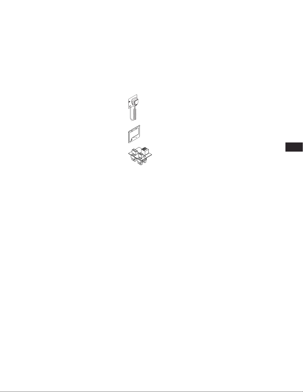
PS-X Packing List
Part Name Qty Description
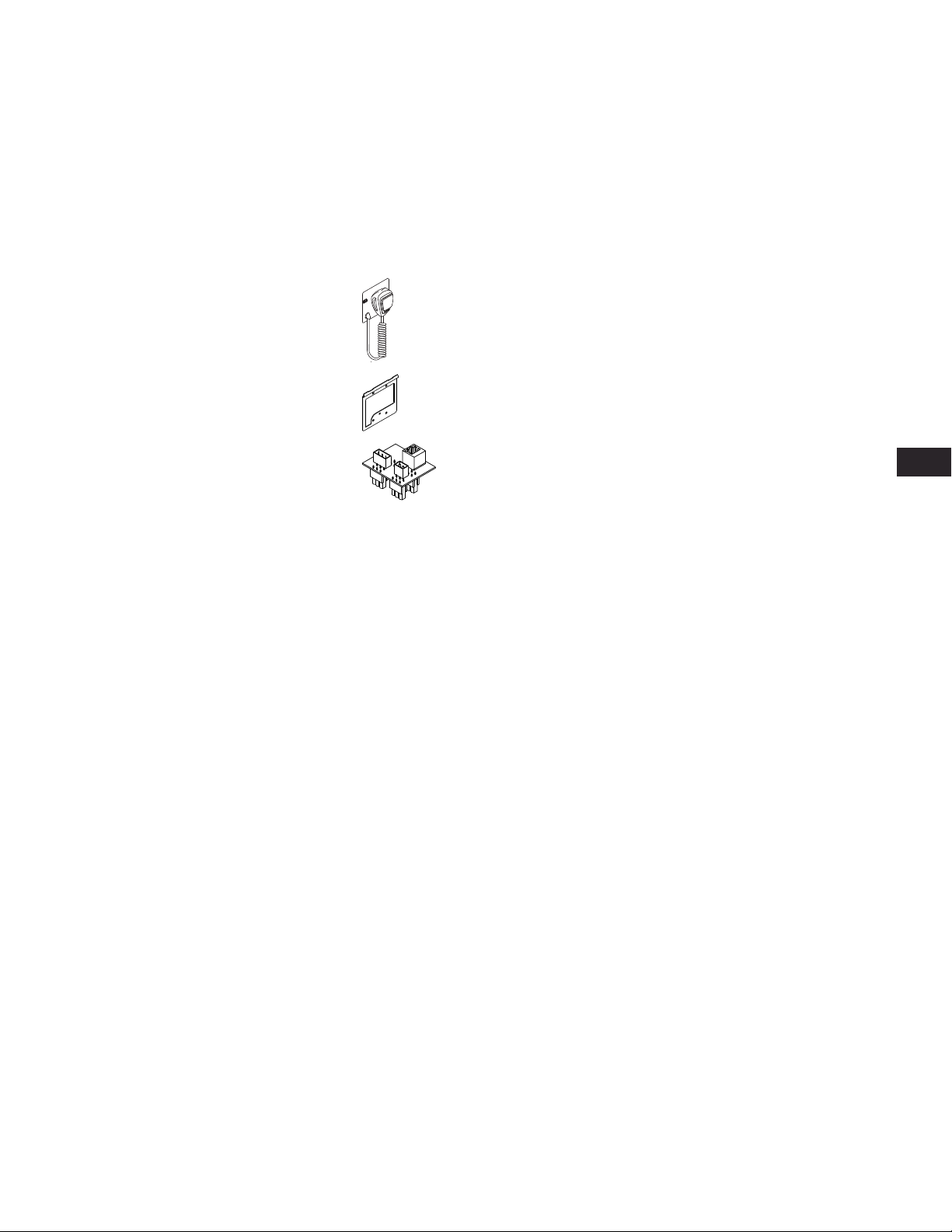
PS-X – Page Station Expander 1
Mounting Bracket 1
Page Station Connector Adapter 1
Flat-head screw 1 #8-32, 0.5"
Warning information sheet 1
Q-Sys PS-X Quick Start Guide 1 TD-000358-00
Installation
The Q-Sys PS-X is mounted using a new construction, UL listed, 2-gang electrical box.
General Requirements
• The PS-X must have access to a Cat 5e connection (RJ45 Class 2) to the associated Q-Sys Page Station.
• The PS-X must be mounted in a wall no less than 2.38” (60.5 mm) deep.
• The PS-X should be mounted in a location where it will not be an obstruction to normal traffi c.
• The Cat 5e cable must be less than or equal to 100 meters.
EN
7
Page 8
Mounting the Mounting Bracket to a 2-Gang Electrical Box - New Construction
NOTE: The mounting procedure for an old-construction
2-gang box is the same, however not all old-construction boxes
will work with the PS-X. Be sure you verify the fi t before installing
the old-construction box in the wall.
EN
The 2-gang electrical box must be UL listed, and should be installed in the wall,
during construction, with the Cat 5e cable pre-wired.
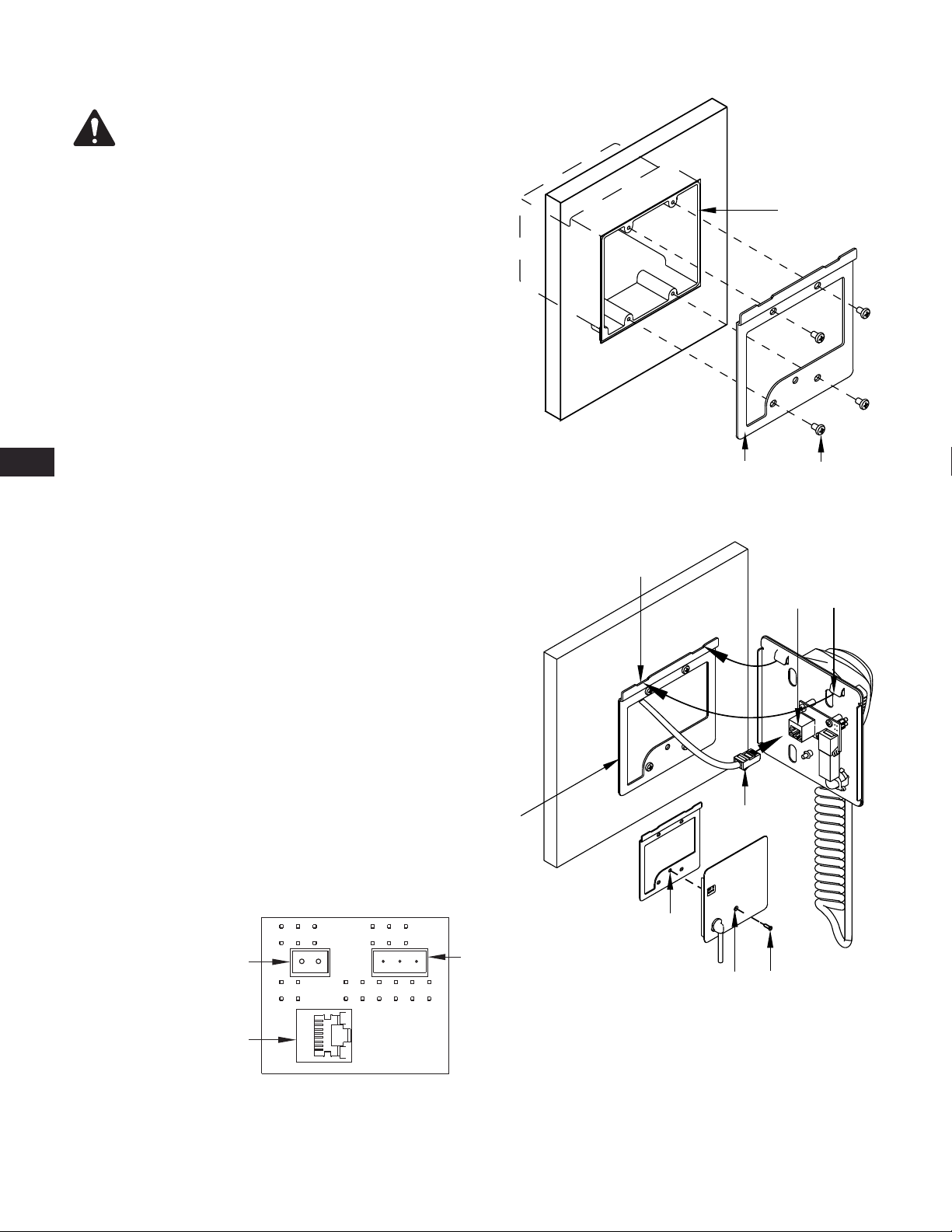
Refer to Figure 4.
1. Place the Mounting Bracket on the wall aligning the holes in the Mounting
Bracket (2) with the holes in the 2-gang box (1).
2. Use four Mounting Bracket Screws (3) and an appropriate screwdriver to
secure the Mounting Bracket to the 2-gang box.
Mounting the PS-X to the Mounting Bracket
Refer to Figure 5.
1. Feed the Cat 5e cable (1) with a Class 2 RJ45 connector, through the
Mounting Bracket (2), and plug it into the RJ45 socket (3) on the back of
the PS-X.
2. Carefully angle the top of the PS-X forward (towards the wall), and slide the
PS-X onto the Mounting Bracket (1) inserting the two mounting tabs (4)
into the mounting tab receptacles (5). Make sure the cable is fed carefully
into the box or wall and is not binding anywhere.
3. After engaging the tabs, straighten the PS-X, pull slightly down, and push in
on the bottom.
— Figure 4 —
5
1
2
3
4
3
4. Secure the PS-X to the Mounting Bracket with one counter sunk Phillips
screw (5) inserted in the hole (6) in the PS-X microphone docking plate.
Page Station Connector Adaptor Labeling
Refer to Figure 6
When you connect the adapter to the Page Station, it makes use of the GPIO
and Mic/Line connectors on the Page Station and the labels on the back of the
Page Station are no longer relevant. Refer to the Page Station User Manual for
details. The following Page Station connectors are available for use.
1. RJ-45 connector to the PS-X (J5)
2. Aux Power (J4)
3. Line Out (J5)
2
1
J4
J5
— Figure 6 —
3
J3
2
8
1
5
6
— Figure 5 —
8
Page 9
Computer Requirements & Software Installation
Confi guration of the PS-X requires a Q-Sys Core Processor, a PC running Q-Sys Designer software, and a Q-Sys Page Station both connected to the
Q-LAN network. The latest version of Q-Sys Designer may be downloaded from the QSC website (http://www.qscaudio.com/). Additionally, all Q-Sys
Core Processors include a Q-Sys Designer CD-ROM. For more information regarding system requirements and installation instructions, refer to the
Q-Sys Designer installation instructions on the QSC website or in the Core Processor's Q-Sys Hardware User Manual.
Connections
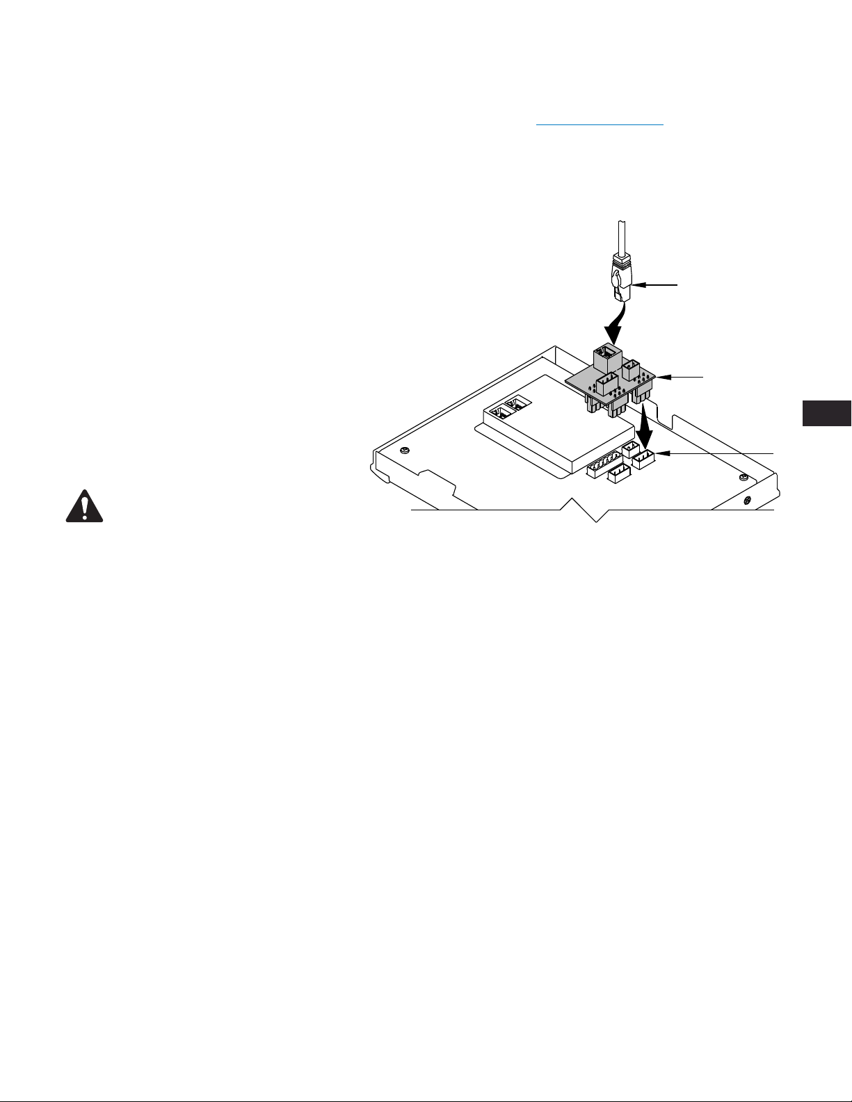
The Q-Sys Page Station Expander connects to any of the
Q-Sys Page Station models. A Cat 5e cable, both ends
terminated with a Class 2 RJ-45 connector, and the Page
Station Connector Adapter is all that is needed. The cable
must be 100 meters or less.
Refer to Figure 7.
1. Plug the Page Station Connector Adapter (1) into the
back of the Page Station (2) as shown.
2. Be sure the adapter is plugged in all the way, and
secure in place.
3. Plug the Cat 5e cable RJ-45 connector (3) into the
RJ-45 receptacle on the adapter.
3
1
EN
2
NOTE: The other end of the Cat 5e cable
should be connected to the PS-X as described
earlier in this document.
Mount or re-mount the Page Station in accordance with
the Page Station User Manual.
— Figure 7 —
Confi guring the Page Station for the PS-X in Q-Sys
Before you can use the PS-X, you must confi gure the Page Station in Q-Sys Designer.
1. Start Q-Sys Designer on the PC.
2. Open the design running on the appropriate Core.
3. In Q-Sys Designer, be sure the Page Station is in the design, then select the Status component of the Page Station to which the PS-X is connected.
4. In the Properties for the Page Station, set the Enable Expander to Yes.
5. Open the Mic/Control component for the Page Station. There are now two sets of controls. One for the Main Mic, the other for the Expander
(Xpander). Use these controls to set the correct levels for the PS-X. Refer to the online help for details.
The PS-X is now ready to use. The PC is no longer required for the operation of your Q-Sys system.
9
Page 10

EN
Using the PS-X
For the most part, using the PS-X depends on the confi guration of the Page Station in the design created for your installation by your system designer.
To make a page, the Ready LED on the PS-X must be illuminated, then just hold the handheld mic button, and begin talking. Release the button when
you are fi nished. Review the Page Station documentation, both the user manual and the online help for Page Station confi guration.
Identifying the PS-X in Q-Sys Designer
If you have a large number of PS-Xs in your design, it may be diffi cult to fi nd which component in the design matches a specifi c piece of hardware.
The way to locate the PS-X is to locate the Page Station to which it is connected.
1. Click the ID button in the Page Station Status component in Q-Sys Designer, or the Page Station in Q-Sys Confi gurator. The LCD on the associated
Page Station fl ashes.
Updating Firmware
There is no fi rmware residing on the PS-X. Firmware updates are made to the Page Station. Refer to the Page Station user manual, or the Q-Sys
Designer online help.
10
Page 11
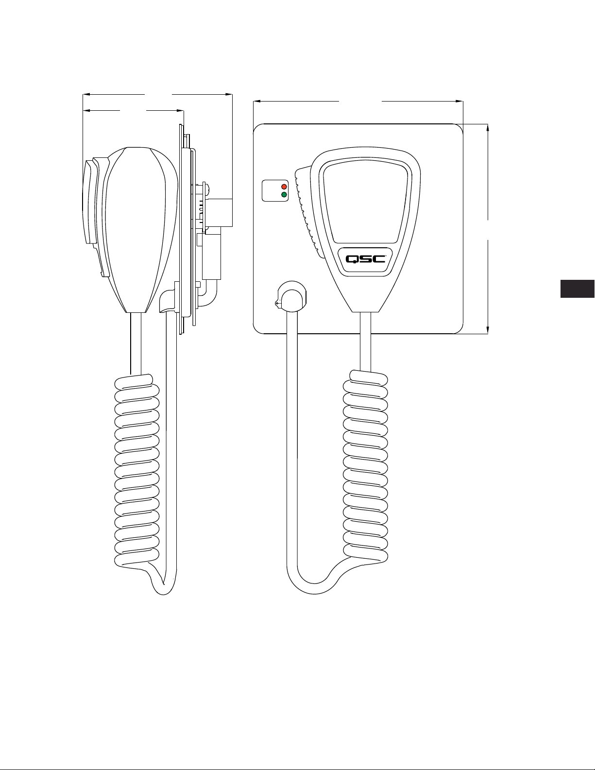
PS-X Dimensions
The microphone cord is not included in the dimensions.
3.56 in.
(90.42 mm)
2.41 in.
(31.21 mm)
5 in.
(127.0 mm)
BUSY
READY
5 in.
(127.0 mm)
EN
— Figure 8 —
11
Page 12

EN
PS-X Specifi cations
Front Panel
Microphone Handheld, push-to-talk, dynamic microphone
Microphone docking surface Ferromagnetic material
Status LEDs Green = Ready, Red = Busy
Status LED Power Source Q-Sys Page Station GPIO
Digital one = TTL 3.3 VDC @ 2 mA
Digital zero is 0 V
Rear Panel Connectors
RJ45 Cat 5e Connection to a Q-Sys Page Station
Dimensions (HWD)
Microphone docking surface 5 in. x 5 in. x 3.56 in. (127.0 mm x 127.0 mm x 90.42 mm)
Shipping Weight 2 lbs. (0.90 kg)
12
Page 13

Contact
Support
Mailing Address
QSC Audio Products, LLC
1675 MacArthur Boulevard
Costa Mesa, CA 92626-1468 U.S.
Main Number
(714) 754-6175
World Wide Web
www.qscaudio.com
Sales & Marketing
Voice
(714) 957-7100 International
Toll free (U.S. only) (800) 854-4079
FAX
(714) 754-6174
E-mail
24/7 Support
QSC offers 24/7 support on Q-Sys™
Networked Audio Systems only.
Q-Sys™ Customer Support
Full Support
Business Hours: 6 AM to 5 PM Pacifi c Time (Mon-Fri)
Tel. 800-772-2834 (U.S. only)
Tel. +1 (714) 957-7150
Fax. +1 (714) 754-6173
Q-Sys Emergency-only After-Hours and Weekend Support*
Tel: +1-888-252-4836 (U.S./Canada)
Tel: +1-949-791-7722 (non-U.S.)
* After hours calls are guaranteed a 30 minute response time from a
Q-Sys Support Team member for Q-Sys ONLY!
E-mail
qsyssupport@qscaudio.com
(immediate e-mail response not guaranteed. For URGENT issues use
the phone numbers above.)
EN
info@qscaudio.com
© 2011 - 2012 QSC Audio Products, LLC. All rights reserved. QSC and the QSC logo are registered trademarks of QSC Audio Products, LLC in the U.S. Patent and Trademark
offi ce and other countries. Q-Sys, Q-LAN, Q-Sys Core Processor, Q-Sys Core 1000, Q-Sys Core 3000, Q- Sys Core 4000, Q-Sys I/O Frame, and Q-Sys Designer are trademarks of
“Windows” is a trademark of Microsoft Corp. All other trademarks are the property of their respective owners.
QSC Audio Products, LLC Patents may apply or be pending.
Page 14

™
Manual del usuario del hardware
PS-X – Page Station Expander
Page 15
EXPLICACIÓN DE LOS TÉRMINOS Y DE LOS SÍMBOLOS
El término “¡ADVERTENCIA!” indica instrucciones con respecto a la seguridad personal. Si no se siguen dichas instrucciones, se pueden ocasionar
lesiones corporales o la muerte.
El término “¡PRECAUCIÓN!” indica instrucciones con respecto a posibles daños al equipo físico. Si no se siguen dichas instrucciones, se pueden
ocasionar daños al equipo que pueden no estar cubiertos bajo la garantía.
El término “¡IMPORTANTE!” indica instrucciones o información que son vitales para completar satisfactoriamente el procedimiento.
El término “NOTA” se utiliza para indicar información adicional de utilidad.
La intención del símbolo de un rayo con punta de fl echa dentro de un triángulo equilátero es alertar al usuario de la presencia de
voltaje “peligroso” no aislado dentro de la caja del producto, que puede ser de sufi ciente magnitud para constituir un riesgo de descarga
eléctrica a los seres humanos.
La intención del signo de exclamación dentro de un triángulo equilátero es alertar al usuario de la presencia de importantes
instrucciones de seguridad, operación y mantenimiento en este manual.
INSTRUCCIONES IMPORTANTES DE SEGURIDAD
ES
¡ADVERTENCIA!: PARA PREVENIR INCENDIOS O DESCARGAS ELÉCTRICAS, NO EXPONGA ESTE EQUIPO A LA LLUVIA NI
A LA HUMEDAD.
- La máxima temperatura ambiente de operación es 50 °C (122 °F).
• Lea estas instrucciones.
• Conserve estas instrucciones.
• Ponga atención a todas las advertencias.
• Siga todas las instrucciones.
• No use este aparato cerca del agua.
• Límpielo sólo con un paño seco.
• No obstruya ninguna abertura de ventilación. Instale el equipo de acuerdo con las instrucciones del fabricante.
• No lo instale cerca de fuentes de calor tales como radiadores, registros térmicos, estufas ni otros aparatos (inclusive amplifi cadores)
que produzcan calor.
• Use sólo piezas/accesorios especifi cados por el fabricante.
• Desconecte el aparato durante tormentas eléctricas o cuando no lo vaya a usar durante periodos prolongados.
• Refi era todo el servicio a personal califi cado. Es necesario dar servicio al aparato cuando sufra algún daño, como cuando se daña el cable de
alimentación eléctrica o el enchufe, cuando se derraman líquidos o caen objetos sobre el aparato, cuando éste haya estado expuesto a la lluvia
o humedad, cuando no opere normalmente o cuando se haya caído.
• Cumpla con todos los códigos locales aplicables.
• Consulte a un ingeniero profesional con la debida licencia cuando surjan dudas o preguntas referentes a la instalación física del equipo.
Diseñado y montado en EE.UU.
2
Page 16

Declaración de la FCC
NOTA: Este equipo ha sido probado y se ha determinado que cumple con los límites de un dispositivo digital Clase B, en virtud de la
parte 15 de las reglas de la FCC.
Estos límites están diseñados para proporcionar protección razonable contra interferencia dañina en una instalación residencial. Este equipo genera,
utiliza y puede irradiar energía de radiofrecuencia y por lo tanto, si no se instala y utiliza de conformidad con las instrucciones, podría causar
interferencia dañina para las radiocomunicaciones. Sin embargo, no hay garantía que no ocurrirá interferencia en una instalación en particular. Si este
equipo interfi ere con la recepción de radio o televisión, lo cual se puede determinar encendiendo y apagando el equipo, se recomienda al usuario
que trate de corregir la interferencia con uno de los siguientes métodos:
• Reoriente o reubique la antena receptora.
• Aumente la separación entre el equipo y el receptor.
• Conecte el equipo en un tomacorriente de un circuito diferente al cual está conectado el receptor.
• Consulte al distribuidor o a un técnico experimentado de radio o TV para solicitar ayuda.
Garantía (sólo para EE.UU.; para otros países, consulte con su vendedor
o distribuidor)
Garantía limitada de 3 años de QSC Audio Products
QSC Audio Products, LLC (“QSC”) garantiza que sus productos estarán libres de materiales y/o mano de obra defectuosos y reemplazará las piezas
defectuosas y reparará los productos que funcionen mal bajo esta garantía cuando el defecto ocurra bajo condiciones normales de instalación
y uso, siempre y cuando la unidad se devuelva a nuestra fábrica, a una de nuestras estaciones autorizadas de servicio o a un distribuidor autorizado
de QSC International mediante transportación prepagada con una copia del comprobante de compra (por ejemplo, el recibo de la compra). Esta
garantía requiere que la inspección del producto devuelto indique, en nuestra opinión, un defecto de fabricación. Esta garantía no se extiende
a ningún producto que haya estado sometido a uso indebido, negligencia, accidente, instalación incorrecta, o al que se haya quitado o modifi cado
el código de la fecha. QSC tampoco será responsable por daños incidentales y/o emergentes. Esta garantía le otorga derechos legales específi cos.
Esta garantía limitada es transferible durante el período de la misma. La garantía de los productos QSC NO ES VÁLIDA si los productos se compraron
de un distribuidor no autorizado o de un comerciante en línea, o si el número de serie original de fábrica se quita, altera o reemplaza de alguna
manera. El daño o pérdida de cualquier software o datos que residan en el producto no está cubierto por la garantía. Al proporcionar servicio de
reparación o reemplazo, QSC hará todos los esfuerzos razonables para reinstalar la confi guración original del software del producto y las versiones
de actualización subsiguientes, pero no ofrece la recuperación ni la transferencia del software o de los datos contenidos en la unidad a la que se
dio servicio que no estaban incluidos originalmente en el producto.
Los clientes podrían tener derechos adicionales, que varían de un estado a otro o de un país a otro. En el caso de que las leyes locales anulen,
prohíban o suspendan una disposición de esta garantía limitada, las disposiciones remanentes permanecerán en vigencia.
La garantía limitada de QSC es válida por un periodo de tres (3) años a partir de la fecha de compra en Estados Unidos y en muchos otros
países (pero no en todos).
Si desea información sobre la garantía de QSC en países que no sean Estados Unidos, comuníquese con su distribuidor internacional de QSC
autorizado. Puede encontrar una lista de los distribuidores internacionales de QSC en www.qscaudio.com.
Para registrar su producto QSC en línea, visite www.qscaudio.com y seleccione ”Product Registration” (Registro del producto). Puede recibir respuesta
a otras preguntas referentes a esta garantía llamando, enviando un mensaje electrónico o comunicándose con su distribuidor QSC autorizado.
ES
Teléfono: 1-800-854-4079 en EE.UU. y Canadá, +1-714-754-6175 internacional. Correo electrónico: warranty@qscaudio.com.
Sitio web: www.qscaudio.com.
3
Page 17
ES
DECLARACIÓN DE LA RoHS
Los productos Q-Sys PS-X están en cumplimiento con la Directiva Europea 2002/95/EC – Restricción de sustancias peligrosas (Restriction of Hazardous
Substances, RoHS).
Los productos Q-Sys PS-X están en cumplimiento con las directivas “RoHS para China”. Se proporciona el cuadro siguiente para la utilización del
producto en China y sus territorios:
Q-Sys PS-X
部件名称
(Número de pieza)
铅
(Pb)
电路板组件
(Conjuntos PCB)
机壳装配件
(Conjuntos de chasis)
O: 表明这些有毒或有害物质在部件使用的同类材料中的含量是在 SJ/T11363_2006 极限的要求之下。
(O: Indica que esta sustancia tóxica o peligrosa contenida en todos los materiales homogéneos de esta pieza se encuentra por debajo del
requisito límite de SJ/T11363_2006.)
X: 表明这些有毒或有害物质在部件使用的同类材料中至少有一种含量是在 SJ/T11363_2006极限的要求之上。
(X: Indica que esta sustancia tóxica o peligrosa contenida en al menos uno de los materiales homogéneos usados en esta pieza se encuentra
por arriba del requisito límite de SJ/T11363_2006.)
XOOO O O
XOOO O O
汞
(Hg)
(Sustancias y elementos tóxicos o peligrosos)
有毒有害物质或元素
镉
(Cd)
六价铬
(Cr(vi))
多溴联苯
(PBB)
多溴二苯醚
(PBDE)
4
Page 18
Introducción
El Page Station Expander está diseñado para montarse en la pared, alojado en una caja eléctrica de pared de doble acoplamiento EU estándar
y se conecta directamente a la parte posterior de la Q-Sys Page Station mediante un cable Cat 5e. La entrada de voz se proporciona a través
de un micrófono dinámico de mano que se presiona para hablar. Un exclusivo sistema de acoplamiento magnético y el liberador de tensión del
cable permiten fl exibilidad en la colocación del micrófono cuando no está en uso, y a la vez ayudan a disuadir el robo o la remoción del micrófono.
La combinación del Page Station Expander y la Page Station propiamente dicha proporcionan múltiples entradas para una zona común, por ejemplo,
tanto el quiosco como la manga de abordaje de una puerta de embarque del aeropuerto pueden ser fácilmente servidas por esta combinación.
Si desea obtener información detallada sobre las Q-Sys Page Stations y la red Q-LAN, consulte la Guía del usuario de la Page Station y la ayuda
en línea de Q-Sys Designer.
Características del Page Station Expander
1
1
2
3
4
BUSY
READY
— Figure 1 —
1. Indicadores LED Ocupado
y Listo
2. Botón Presionar para hablar
3. Superfi cie magnética
4. Liberador de tensión de
fi jación
1. Lengüetas de montaje
2. Conector RJ-45 (a la Page
Station)
ES
2
3
4
— Figure 2 —
3. Orifi cio del tornillo de montaje
4. Liberador de tensión de
fi jación
5
Page 19
La red Q-LAN de Q-Sys
La solución Q-Sys (Figura 3) está diseñada para ser desplegada en una red Q-LAN de alto rendimiento de QSC. Q-LAN es una implementación de
red patentada que reúne varios protocolos estándar en la industria en una solución de transporte de datos apropiada para entornos multimedia
de presentaciones en vivo. Q-LAN ofrece velocidades de datos en gigabits, redundancia de dispositivos y redes, transferencias de datos de audio
de punto fl otante de 32 bits, y apoyo de latencia baja en despliegues de redes de área local. La sincronización exacta de los nodos en los extremos
y la distribución de relojes de alta calidad quedan incorporadas en la solución Q-LAN utilizando el protocolo de tiempo de precisión IEEE-1588.
El descubrimiento de los nodos en los extremos y la confi guración automática de dichos nodos están incluidos en la solución utilizando protocolos
estándar en la industria sobre una implementación de red IP basada en las normas usando componentes de hardware listos para usar.
Figura 3 muestra una implementación de red Q-LAN muy sencilla con un procesador Q-Sys Core, un equipo Q-Sys I/O Frame, un Q-Sys PS-X Page
Station Expander, un interruptor Ethernet y una PC con Q-Sys Designer.
Todos los dispositivos están conectados a un interruptor de Ethernet de 1000 Mbps administrado que incluye la calidad de servicio (QoS) apropiada
idónea para una red en gigabits de alto rendimiento para apoyar aplicaciones multimedia.
El PS-X está confi gurado vía Q-Sys Designer cuando usted confi gura su Page Station.
NOTA: Sólo se requiere una PC durante la confi guración inicial del sistema o cuando una PC es el medio preferido para proporcionar
servicios permanentes de administración al diseñador u operador del sistema.
ES
Q-Sys I/O Frame Windows PC
Conmutador Ethernet
Ethernet Switch
Q-Sys Core
PC con Windows
Q-Sys Page Station Expander
PS-X
— Figure 3 —
• El equipo Q-Sys I/O Frame proporciona un punto de acceso de audio para el sistema Q-Sys proporcionando los medios para activar y desactivar el
audio de la red Q-LAN.
• El procesador Q-Sys Core proporciona servicios de procesamiento, distribución y administración de la señal para el sistema Q-Sys. Todas las
comunicaciones de audio y administración sensibles al tiempo atraviesan la red Q-LAN.
• La PC con Windows puede ser una computadora de escritorio o una portátil con Q-Sys Designer o la aplicación de administración remota Interfaz
de Control del Usuario (User Control Interface, UCI). El sistema Q-Sys sólo requiere la PC durante la fase de diseño para la confi guración del
sistema. No se requiere la PC para la operación en tiempo de ejecución, si bien puede utilizarse para una administración permanente del sistema.
• El Q-Sys PS-X junto con la Q-Sys Page Station y el procesador Core proporcionan la capacidad de usar dos micrófonos dedicados para una sola
Page Station en la misma área física.
6
Page 20
Desembalaje
No hay precauciones especiales para el desembalaje. Sin embargo, se recomienda guardar los materiales originales de empaque para volver
a utilizarlos en el caso raro de requerirse servicio. Si se requiere servicio y no está disponible el material original de empaque, asegúrese de que la
unidad quede adecuadamente protegida para el envío (utilice una caja resistente de tamaño apropiado, sufi ciente material de empaque/acolchado
para evitar el desplazamiento de la carga o daños por impacto) o llame al Grupo de Servicios Técnicos de QSC para solicitar material de empaque
y una caja de reemplazo.
Lista de piezas PS-X incluidas en el empaque
Nombre de la pieza Cant. Descripción
Page Station Expander 1
Soporte de montaje 1
Adaptador del conector de la Page Station 1
ES
Tornillo de cabeza plana 1 #8-32, 0,5"
Hoja de información de advertencia 1
Guía de inicio rápido de Q-Sys PS-X 1 TD-000358-00
Instalación
El Q-Sys PS-X se monta con una caja eléctrica de doble acoplamiento, aprobada por UL y de construcción nueva.
Requisitos generales
• El PS-X debe tener acceso a una conexión Cat 5e (RJ45 Clase 2) a la Q-Sys Page Station.
• El PS-X debe estar montado en una pared con una profundidad no menor de 2,38” (60,5 mm).
• El PS-X debe estar montado en un lugar en donde no obstruya el tráfi co normal.
• El cable Cat 5e debe tener una longitud de 100 metros o menos.
7
Page 21

ES
Instalación del soporte de montaje a una caja eléctrica de doble acoplamiento, construcción nueva
NOTA: El procedimiento de montaje de una caja de doble
acoplamiento de construcción vieja es el mismo; sin embargo,
no todas las cajas de construcción vieja funcionarán con el PS-X.
Asegúrese de verifi car el ajuste antes de instalar en la pared la caja
de construcción vieja.
1
La caja eléctrica de doble acoplamiento debe ser aprobada por UL, y durante la
construcción se debe instalar en la pared con el cable Cat 5e precableado.
Consulte Figura 4.
1. Coloque el soporte de montaje en la pared alineando los orifi cios del
soporte (2) con los orifi cios de la caja de doble acoplamiento (1).
2. Use cuatro tornillos del soporte de montaje (3) y un destornillador
apropiado para fi jar el soporte de montaje en la caja de doble acoplamiento.
Instalación del PS-X en el soporte de montaje
Consulte Figura 5.
1. Pase el cable Cat 5e (1) con un conector RJ45 clase 2 a través del soporte
de montaje (2), y enchúfelo en el receptáculo RJ45 (3) que se encuentra en
la parte posterior del PS-X.
2
— Figure 4 —
3
2. Con cuidado incline la parte superior del PS-X hacia adelante (hacia la
pared) y deslice el PS-X en el soporte de montaje (1) insertando las dos
lengüetas de montaje (4) en los receptáculos de estas lengüetas (5).
Asegúrese de que el cable pase cuidadosamente a la caja o la pared y que
no esté atorado en ningún lugar.
3. Después de embragar las lengüetas, enderece el PS-X, jale ligeramente
hacia abajo y empuje sobre la parte inferior.
4. Asegure el PS-X al soporte de montaje con un tornillo Phillips de cabeza
embutida (5) insertado en el orifi cio (6) de la placa de acoplamiento del
micrófono PS-X.
Rotulado del adaptador del conector de la Page Station
Consulte Figura 6
Cuando conecta el adaptador a la Page Station, se usan los conectores GPIO
y Mic/Line de la estación y los rótulos de la parte de atrás de la estación ya no
son relevantes. Consulte los detalles en el Manual del usuario de la Page Station.
Los siguientes conectores de la Page Station están disponibles para usarse.
1. Conector RJ-45 al PS-X
(J5)
2. Aux Power (J4)
3. Line Out (J5)
2
J4
3
J3
5
4
3
2
8
1
5
6
— Figure 5 —
1
J5
— Figure 6 —
8
Page 22

Requerimientos de la computadora e instalación del software
La confi guración del PS-X requiere un procesador Q-Sys Core, una PC con el software Q-Sys Designer y una Q-Sys, ambas conectadas a la red Q-LAN.
La versión más reciente de Q-Sys Designer se puede bajar del sitio Web de QSC (http://www.qscaudio.com/). Además, todos los procesadores Q-Sys Core
incluyen un CD-ROM de Q-Sys Designer. Si desea más información referente a los requerimientos del sistema y las instrucciones de instalación, consulte
las instrucciones de instalación de Q-Sys Designer en el sitio Web de QSC o en el Manual del usuario del hardware Q-Sys del procesador Core.
Conexiones
El Q-Sys Page Station se conecta a cualquiera de los
modelos de la Q-Sys Page Station. Todo lo que se necesita
es un cable Cat 5e cuyos extremos tengan un conector
RJ-45 clase 2 y el adaptador del conector de la Page Station.
El cable debe tener una longitud de 100 metros o menos.
Consulte Figura 7.
1. Enchufe el adaptador del conector de la Page Station (1) en
la parte posterior de la Page Station (2) como se muestra.
2. Asegúrese de que el adaptador esté totalmente
conectado y fíjelo.
3. Enchufe el conector RJ-45 del cable Cat 5e (3) en el
receptáculo RJ-45 del adaptador.
3
1
2
ES
NOTA: El otro extremo del cable Cat 5e
se debe conectar al PS-X como se describió
anteriormente en este documento.
Monte o vuelva a montar la Page Station de acuerdo con
las instrucciones del Manual del usuario de la Page Station.
— Figure 7 —
Confi guración de la Page Station para el PS-X en Q-Sys
Antes de poder usar el PS-X debe confi gurar la Page Station en Q-Sys Designer.
1. Inicie Q-Sys Designer en la PC.
2. Abra el diseño en el procesador Core apropiado.
3. En Q-Sys Designer, asegúrese de que la Page Station esté en el diseño, luego seleccione el componente Status (Estado) de la Page Station donde
el PS-X está conectado.
4. En Properties (Propiedades) de la Page Station, ajuste Enable Expander (Activar extensor) en Yes (Sí).
5. Abra el componente Mic/Control de la Page Station. Ahora hay dos conjuntos de controles. Uno para el micrófono principal (Main Mic) y el otro
para el extensor (Xpander). Use estos controles para ajustar los niveles correctos para el PS-X. Consulte la ayuda en línea para ver los detalles.
Ahora el PS-X está listo para usar. Ya no se requiere la PC para la operación de su sistema Q-Sys.
9
Page 23

ES
Uso del PS-X
En su mayor parte, el uso del PS-X depende de la confi guración de la Page Station en el diseño creado por su diseñador del sistema para su instalación.
Para hacer un anuncio de localización, el LED Ready (Listo) del PS-X debe estar iluminado, luego simplemente mantenga presionado el botón del
micrófono de mano y comience a hablar. Cuando termine libere el botón. Revise la documentación de la Page Station, tanto el manual del usuario
como la ayuda en línea, para ver la confi guración de la Page Station.
Identifi cación del PS-X en Q-Sys Designer
Si tiene un gran número de PS-X en su diseño, puede ser difícil encontrar el componente del diseño que corresponde a una pieza de hardware
específi ca. La manera de localizar el PS-X es encontrar la Page Station a la cual está conectado.
1. Haga clic en el botón ID del componente Status de la Page Station en Q-Sys Designer, o la estación de radiolocalización en el confi gurador Q-Sys.
El LCD de la Page Station asociada destella.
Actualización del fi rmware
El PS-X no contiene fi rmware. Las actualizaciones del fi rmware se hacen en la Page Station. Consulte el manual del usuario de la Page Station
o la ayuda en línea de Q-Sys Designer.
10
Page 24

Dimensiones del PS-X
No se incluye el cable del micrófono en las dimensiones.
3.56 in.
(90.42 mm)
2.41 in.
(31.21 mm)
5 in.
(127.0 mm)
BUSY
READY
5 in.
(127.0 mm)
ES
— Figure 8 —
11
Page 25

ES
Especifi caciones del PS-X
Panel frontal
Micrófono Micrófono dinámico de mano que se presiona para hablar
Superfi cie de acoplamiento del micrófono Material ferromagnético
LED de estado Verde = Listo; Rojo = Ocupado
LED de estado de la fuente de potencia Q-Sys Page Station GPIO
Digital uno = TTL 3,3 VCC a 2 mA
Digital cero es 0 V
Conectores del panel posterior
RJ45 Conexión Cat 5e a una Q-Sys Page Station
Dimensiones (HWD)
Superfi cie de acoplamiento del micrófono 5 x 5 x 3,56 pulg. (127,0 x 127,0 x 90,42 mm)
Peso de envío 2 lbs. (0,90 kg)
12
Page 26

Contacto
Asistencia
Dirección postal
QSC Audio Products, LLC
1675 MacArthur Boulevard
Costa Mesa, CA 92626-1468 EE.UU.
Número principal
(714) 754-6175
World Wide Web
www.qscaudio.com
Ventas y comercialización
Voz
(714) 957-7100 Internacional
Línea telefónica sin costo (sólo EE.UU.) (800) 854-4079
FAX
(714) 754-6174
Dirección electrónica
info@qscaudio.com
Asistencia 24/7
QSC ofrece asistencia 24/7 solamente para
los sistemas de audio conectados Q-Sys™.
Q-Sys™ Customer Support
Asistencia completa
Horario hábil: de lunes a viernes de 6 AM a 5 PM hora del Pacífi co
Tel. 800-772-2834 (sólo EE.UU.)
Tel. +1 (714) 957-7150
Fax. +1 (714) 754-6173
Asistencia sobre Q-Sys en horas no hábiles y fi nes de semana solamente
en emergencias*
Tel: +1-888-252-4836 (EE.UU./Canadá)
Tel: +1-949-791-7722 (fuera de EE.UU.)
* Para las llamadas en horas no hábiles se garantiza un tiempo de
respuesta de 30 minutos de un miembro del equipo de Asistencia de
Q-Sys ¡SOLAMENTE para sistemas Q-Sys!
Dirección electrónica
qsyssupport@qscaudio.com
(no se garantiza una respuesta electrónica inmediata. Si su problema
es URGENTE llame a los números telefónicos que se indican arriba.)
ES
© 2011 – 2012 QSC Audio Products, LLC. Reservados todos los derechos. QSC y el logotipo de QSC son marcas comerciales registradas de QSC Audio Products, LLC en la
Ofi cina de Patentes y Marcas Comerciales de EE.UU. y en otros países. Q-Sys, Q-LAN, Q-Sys Core Processor, Q-Sys Core 1000, Q-Sys Core 3000, Q-Sys Core 4000,
Q-Sys I/O Frame y Q-Sys Designer son marcas comerciales de QSC Audio Products, LLC. Pueden aplicar patentes o haber patentes pendientes.
“Windows” es una marca comercial de Microsoft Corp. Todas las demás marcas comerciales son propiedad de sus respectivos propietarios.
Page 27

™
Manuel de l'utilisateur du matériel
PS-X– Page Station Expander
Page 28

EXPLICATION DES TERMES ET DES SYMBOLES
La mention « AVERTISSEMENT ! » indique des instructions concernant la sécurité personnelle. Risque de blessures ou de mort si les instructions ne
sont pas suivies.
La mention « ATTENTION ! » indique des instructions concernant des dégâts possibles pour le matériel. Risque de dégâts matériels non couverts par
la garantie si ces instructions ne sont pas suivies.
La mention « IMPORTANT ! » indique des instructions ou des informations vitales à l'exécution de la procédure.
La mention « REMARQUE » indique des informations utiles supplémentaires.
L'éclair fl éché situé dans un triangle a pour objet de signaler à l'utilisateur la présence d'une tension « dangereuse » non isolée dans le
boîtier du produit suffi sante pour présenter un risque d'électrocution pour l'homme.
Le point d'exclamation dans un triangle équilatéral a pour objet de signaler à l'utilisateur la présence de consignes de sécurité et
d'instructions importantes d'utilisation et de maintenance dans ce manuel.
CONSIGNES DE SÉCURITÉ IMPORTANTES
FR
AVERTISSEMENT!: POUR ÉCARTER LES RISQUES D’INCENDIE ET D’ÉLECTROCUTION, NE PAS EXPOSER CE MATÉRIEL
À LA PLUIE OU L’HUMIDITÉ.
– La température ambiante maximale de fonctionnement est de 50 °C.
• Lire ces instructions.
• Conserver ces instructions.
• Respecter tous les avertissements.
• Suivre toutes les instructions.
• Ne pas utiliser cet appareil près de l'eau.
• Nettoyer uniquement avec un chiffon sec.
• Ne pas bloquer les bouches d'aération. Installer conformément aux instructions du fabricant.
• N'installer à proximité d'aucune source de chaleur comme des radiateurs, des registres de chaleur, des poêles ou d'autres appareils (y compris des
amplis) qui dégagent de la chaleur.
• Utiliser uniquement les accessoires spécifi és par le fabricant.
• Débrancher l'appareil en cas d'orage électrique ou lorsqu'il est inutilisé pendant longtemps.
• Confi er toutes les réparations à un personnel qualifi é. Une réparation s'impose lorsque l'appareil a été endommagé d'une manière quelconque,
par exemple endommagement du cordon d'alimentation ou de sa fi che, déversement de liquide ou chute d'objets sur ou à l'intérieur de l'appareil,
exposition de l'appareil à la pluie ou l'humidité, fonctionnement anormal ou chute de l'appareil.
• Respecter tous les codes locaux applicables.
• Consulter un technicien professionnel diplômé en cas de doute ou de question concernant l'installation physique de l'équipement.
Conçu et assemblé aux États-Unis
2
Page 29

Déclaration FCC
REMARQUE: Suite à des tests, cet appareil s’est avéré conforme aux limites d’un appareil numérique de classe B, dans le cadre de
la section 15 des règlements de la FCC.
Ces limites ont été conçues pour fournir une protection raisonnable contre les interférences nuisibles dans une installation résidentielle. Cet appareil
produit, utilise et peut rayonner une énergie haute fréquence et, s'il n'est pas installé et utilisé conformément aux instructions, il risque d'interférer
avec les communications radio. Toutefois, il n'est pas possible de garantir l'absence d'interférences dans une installation particulière. Si cet appareil
cause des interférences nuisibles à la réception radio ou TV, ce qui peut être déterminé en l'éteignant puis en le rallumant, l'utilisateur est encouragé
à essayer de corriger l'interférence en prenant l'une au moins des mesures suivantes :
• Réorientation ou déplacement de l'antenne réceptrice.
• Éloignement de l'appareil par rapport au récepteur.
• Branchement de l'appareil sur une prise secteur appartenant à un autre circuit que celui du récepteur.
• Sollicitation de l'assistance du revendeur ou d'un spécialiste radio/TV.
Garantie (États-Unis seulement ; dans les autres pays, consulter le revendeur ou
le distributeur)
QSC Audio Products – Garantie limitée de 3 ans
QSC Audio Products, LLC (« QSC ») garantit que ses produits sont dépourvus de tout vice de fabrication et/ou de matériel et remplacera les pièces
défectueuses et réparera les produits qui fonctionnent mal dans le cadre de cette garantie si le défaut survient dans des conditions normales
d'installation et d'utilisation – à condition que l'appareil soit retourné à l'usine, à l'un de nos centres de réparation agréés ou à un distributeur
international QSC agréé en port pré-payé, accompagné d'un justifi catif d'achat (facture, par ex.). Cette garantie prévoit que l'examen du produit
retourné doit indiquer, selon notre jugement, un défaut de fabrication. Cette garantie ne s'étend à aucun produit qui a été soumis à une utilisation
abusive, un acte de négligence, un accident, une installation incorrecte ou un produit dont le code-date a été retiré ou effacé. QSC ne pourra être
tenue pour responsable de dommages accessoires et/ou indirects. Cette garantie vous accorde des droits spécifi ques. Cette garantie limitée est
librement cessible durant sa période de validité. La garantie portant sur les produits QSC n'est PAS VALABLE si les produits ont été achetés chez un
revendeur/vendeur en ligne non agréé, ou si le numéro de série de l'usine a été retiré, effacé ou remplacé d'une manière quelconque. L'altération
ou la perte de tout logiciel ou toute donnée résidant sur le produit n'est pas couverte par la garantie. Pour tout service de réparation ou de
remplacement, QSC consentira des efforts raisonnables pour réinstaller le logiciel du produit à sa confi guration initiale, ainsi que les mises à jour
ultérieures, mais n'assurera pas la récupération ou le transfert de logiciel ou de données contenues sur l'appareil réparé ne fi gurant pas au départ
sur le produit.
Les clients pourront avoir des droits supplémentaires, qui peuvent varier d'un État ou d'un pays à l'autre. Si une disposition de cette garantie limitée
est nulle, interdite ou périmée en vertu des lois locales, les dispositions restantes seront toujours en vigueur.
La garantie limitée QSC est valide pendant une période de trois (3) ans à partir de la date d'achat aux États-Unis et de nombreux autres pays (mais
pas tous).
Pour des informations sur la garantie QSC dans d'autres pays que les États-Unis, contactez votre distributeur international QSC agréé. La liste des
distributeurs internationaux QSC est disponible à www.qscaudio.com.
Pour enregistrer votre produit QSC en ligne, allez à www.qscaudio.com et sélectionnez « Product Registration ». Pour toute autre question sur cette
garantie, appelez, envoyez un courriel ou contactez votre distributeur QSC agréé.
FR
Téléphone : 1-800-854-4079 (États-Unis et Canada), +1-714-754-6175 (international), Courriel : warranty@qscaudio.com, site Web : www.qscaudio.com.
3
Page 30

DÉCLARATION RoHS
Les produits Q-Sys PS-X sont conformes à la Directive européenne 2002/95/CE – Restriction d'utilisation de substances dangereuses pour
l'environnement (RoHS).
Les produits Q-Sys PS-X sont conformes aux directives RoHS chinoises. Le tableau suivant est fourni pour une utilisation du produit en Chine et
sur ses territoires :
Q-Sys PS-X
部件名称
(nom de pièce)
铅
(Pb)
电路板组件
(cartes de circuits
imprimés)
机壳装配件
(châssis)
O: 表明这些有毒或有害物质在部件使用的同类材料中的含量是在 SJ/T11363_2006 极限的要求之下。
XOOO O O
XOOO O O
(substances et éléments toxiques ou dangereux)
汞
(Hg)
有毒有害物质或元素
镉
(Cd)
六价铬
(Cr(vi))
多溴联苯
(PBB)
多溴二苯醚
(PBDE)
FR
(O : Indique que cette substance toxique ou dangereuse contenue dans tous les matériaux homogènes pour cette pièce se situe en dessous
de la limite exigée dans SJ/T11363_2006.)
X: 表明这些有毒或有害物质在部件使用的同类材料中至少有一种含量是在 SJ/T11363_2006极限的要求之上。
(X : indique que cette substance toxique ou dangereuse contenue dans au moins un des matériaux homogènes utilisés pour cette pièce est
au-dessus de la limite indiquée dans SJ/T11363_2006.)
4
Page 31

Introduction
Le PS-X est conçu pour être monté sur un mur dans un boîtier mural électrique double standard et se branche directement sur l'arrière d'une
Q-Sys Page Station via un câble Cat 5e. L'entrée vocale est fournie via un microphone à bouton-poussoir de conversation dynamique portable.
Un système d'amarrage magnétique unique et le réducteur de tension donnent une certaine fl exibilité de placement du microphone lorsqu'il n'est
pas utilisé, mais dissuadent les voleurs et le retrait du microphone. La combinaison du PS-X et de la Page Station fournit des entrées multiples pour
une zone commune ; par exemple, le kiosque et la passerelle d'une porte d'embarquement peuvent facilement être desservis par cette combinaison.
Pour des détails sur les Q-Sys Page Stations et le réseau Q-LAN, voir le guide de l'utilisateur de la Page Station et l'aide en ligne de Q-Sys Designer.
Caractéristiques et fonctions du PS-X
1
1
2
3
4
BUSY
READY
1. Voyant Occupé et Prêt
— Figure 1 —
3. Surface magnétique
2
FR
3
4
1. Onglets de montage
— Figure 2 —
3. Trou de vis de fi xation
2. Bouton-poussoir de
conversation
4. Réducteur de tension
verrouillable
2. Connecteur RJ-45 (à la Page
Station)
5
4. Réducteur de tension
verrouillable
Page 32

Réseau Q-Sys Q-LAN
La solution Q-Sys (Figure 3) a été conçue pour être déployée sur un réseau Q-LAN haute performance de QSC. Q-LAN est un réseau propriétaire
qui réunit plusieurs protocoles standard dans l'industrie en une solution de transport de données appropriée aux environnements multimédia des
spectacles en live. Q-LAN offre des débits de données de l'ordre du gigabit, une redondance périphérique et réseau, des transferts de données audio
à virgule fl ottante 32 bits et un faible temps d'attente sur les déploiements de réseaux locaux. La synchronisation précise des nœuds terminaux et la
distribution d'horloge de haute qualité sont intégrées à la solution Q-LAN à l'aide du protocole de temps de précision IEEE-1588. La découverte et la
confi guration automatique de nœuds terminaux sont incluses à la solution à l'aide de protocoles standard dans l'industrie sur un réseau IP normalisé
qui utilise du matériel standard.
La Figure 3 illustre un réseau Q-LAN très simple comportant un Q-Sys Core Processor, un Q-Sys I/O Frame, un Q-Sys PS-X Page Station Expander,
un commutateur Ethernet et un PC exécutant Q-Sys Designer.
Tous les périphériques sont connectés à un commutateur Ethernet 1000 Mbps qui inclut la QoS (Quality of Service) adaptée à un réseau gigabit haute
performance pour la prise en charge des applications multimédia.
Le PS-X est confi guré via Q-Sys Designer lors de la confi guration de la Page Station.
REMARQUE: Un PC est uniquement requis durant la confi guration initiale du système ou quand un PC est la méthode préférée
pour les prestations de service de gestion continues au concepteur ou à l'opérateur du système.
FR
Q-Sys I/O Frame Windows PC
Commutateur Ethernet
Ethernet Switch
Q-Sys Core
Q-Sys Page Station Expander
PC Windows
PS-X
— Figure 3 —
• Le Q-Sys I/O Frame fournit un point d'accès audio au système Q-Sys en permettant d'obtenir du son sur le réseau Q-LAN et en dehors.
• Le Q-Sys Core Processor assure les services de traitement, distribution et gestion du signal pour le système Q-Sys. Toutes les communications de
gestion et audio temporaires traversent le réseau Q-LAN.
• Le PC Windows peut être un micro-ordinateur ou un ordinateur portable exécutant Q-Sys Designer ou l'application de gestion à distance
User Control Interface (UCI). Le PC est uniquement requis par le système Q-Sys durant la phase de conception pour confi gurer le système.
Le PC n'est pas requis pour l'utilisation, bien qu'il puisse être utilisé pour la gestion continue du système.
• Le Q-Sys PS-X, utilisé en conjonction avec la Q-Sys Page Station et le Core Processor, permettent l'utilisation de deux microphones dédiés pour une
Page Station dans la même zone physique.
6
Page 33

Déballage
Le déballage ne fait l'objet d'aucune précaution particulière. On recommande toutefois de conserver le matériel d'emballage d'origine pour
réutilisation dans l'éventualité rare d'une réparation nécessaire. En cas de réparation nécessaire et en l'absence de matériel d'emballage d'origine,
s'assurer que l'appareil est correctement protégé pour l'expédition (utiliser un carton solide de la taille appropriée, du matériel d'emballage/
rembourrage suffi sant afi n d'éviter le déplacement de la charge et les dégâts causés par des chocs) ou appeler le service technique QSC pour obtenir
du matériel d'emballage et un carton de remplacement.
Liste de colisage du PS-X
Nom du composant Qté Description
PS-X – Page Station Expander 1
Support de fi xation 1
Adaptateur de connecteur Page Station 1
FR
Vis à tête plate 1 #8-32, 0,5"
Feuille d'avertissements 1
Guide de mise en route rapide du Q-Sys PS-X 1 TD-000358-00
Installation
Le Q-Sys PS-X est monté en utilisant une nouvelle construction, listée UL, dans un boîtier électrique double.
Exigences générales
• Le PS-X doit avoir accès via une connexion Cat 5e (RJ45 Classe 2) à la Q-Sys Page Station associée.
• Le PS-X doit être monté dans un mur ne devant pas mesurer moins de 60,5 mm d'épaisseur.
• Le PS-X doit être monté à un endroit où il ne gênera pas le passage.
• Le câble Cat 5e ne doit pas mesurer plus de 100 m.
7
Page 34

FR
Montage du support de fi xation sur un boîtier électrique double – Nouvelle construction
REMARQUE: La procédure de montage pour un boîtier
électrique double de construction ancienne est la même, mais les
boîtiers de construction ancienne ne fonctionneront pas avec le
PS-X. Vérifi er l'ajustement avant d'installer le boîtier de
construction ancienne dans le mur.
1
Le boîtier électrique ouble doit être listé UL et installé dans le mur, durant la
construction, avec le câble Cat 5e précâblé.
Voir Figure 4.
1. Placer le support de fi xation sur le mur en alignant ses trous (2) sur ceux du
boîtier double (1).
2. Utiliser les quatre vis du support de fi xation (3) et un tournevis approprié
pour fi xer le support au boîtier double.
Montage du PS-X au support de fi xation
Voir Figure 5.
1. Enfi ler le câble Cat 5e (1) avec un connecteur RJ45 classe 2 dans le support
de fi xation (2), puis le brancher sur la prise RJ45 (3) à l'arrière du PS-X.
2. Incliner avec précaution le haut du PS-X vers l'avant (vers le mur), puis
glisser le PS-X sur le support de fi xation (1) en insérant les deux onglets de
montage (4) dans les fentes qui leur sont réservées (5). Veiller à enfi ler le
câble dans le boîtier ou le mur sans qu'il ne se coince.
3. Une fois les onglets enclenchés dans les fentes, redresser le PS-X, le tirer
légèrement vers le bas et le pousser au fond.
— Figure 4 —
5
2
3
3
4
4. Fixer le PS-X au support à l'aide d'une vis à tête fraisée cruciforme (5)
insérée dans le trou (6) de la plaque d'amarrage du microphone du PS-X.
Étiquetage de l'adaptateur du connecteur de la Page
Station
Voir Figure 6
Le branchement de l'adaptateur à la Page Station s'effectue via les connecteurs
GPIO et Mic/Line de la Page Station, après quoi les étiquettes au dos de la
Page Station ne sont plus pertinentes. Pour des détails, voir le manuel de
l'utilisateur de la Page Station. Les connecteurs suivants de la Page Station sont
utilisables.
1. Connecteur RJ-45 de branchement sur le PS-X (J5)
2. Alimentation aux. (J4)
3. Sortie de ligne (J5)
2
1
J4
J5
3
J3
2
8
1
5
6
— Figure 5 —
— Figure 6 —
8
Page 35

Confi guration minimale et installation du logiciel
La confi guration du PS-X exige un Q-Sys Core Processor, un PC exécutant le logiciel Q-Sys Designer et une Q-Sys Page Station connectés au Q-LAN. La
dernière version de Q-Sys Designer peut être téléchargée sur le site Web QSC (http://www.qscaudio.com/). Par ailleurs, tous les Q-Sys Core Processors
incluent un CD-ROM Q-Sys Designer. Pour plus d'informations sur la confi guration système minimum et les instructions d'installation, consulter les
instructions d'installation Q-Sys Designer sur le site Web QSC ou le manuel de l'utilisateur du Q-Sys Core Processor.
Branchements
Le Q-Sys PS-X se connecte à n'importe quel modèle de
Q-Sys Page Station. Un câble Cat 5e, terminé à chaque
extrémité par un connecteur RJ-45 Classe 2, et l'adaptateur
de connecteur de Page Station sont tout ce dont vous avez
besoin. Le câble ne doit pas mesurer plus de 100 m.
Voir Figure 7.
1. Brancher l'adaptateur de connecteur de Page Station
(1) sur l'arrière de la Page Station (2), comme illustré.
2. Veiller à l'insérer à fond et à bien le fi xer en place.
3. Brancher le connecteur RJ-45 du câble Cat 5e (3) sur la
prise RJ-45 de l'adaptateur.
REMARQUE: L'autre extrémité du
câble Cat 5e doit être connectée au PS-X
comme décrit plus haut dans ce document.
3
1
2
FR
Monter ou remonter la Page Station conformément au
manuel de l'utilisateur de la Page Station.
— Figure 7 —
Confi guration de la Page Station pour le PS-X dans Q-Sys Designer
Avant d'utiliser le PS-X, la Page Station doit être confi gurée dans Q-Sys Designer.
1. Démarrer Q-Sys Designer sur le PC.
2. Ouvrir le concept utilisant le Core approprié.
3. Dans Q-Sys Designer, veiller à ce que la Page Station apparaisse dans le concept, puis sélectionner le composant Status de la Page Station auquel
le PS-X est connecté.
4. Sous les Properties de la Page Station, régler Enable Expander sur Yes.
5. Ouvrir le composant Mic/Control correspondant à la Page Station. Il y a désormais deux jeux de commandes. L'un pour le microphone principal,
l'autre pour l'Expander (Xpander). Utilisez ces commandes pour régler les niveaux corrects pour le PS-X. Pour des détails, voir l'aide en ligne.
Le PS-X est désormais prêt à l'emploi. Le PC n'est plus requis pour le fonctionnement de votre système Q-Sys.
9
Page 36

FR
Utilisation du PS-X
Pour l'essentiel, l'utilisation du PS-X dépend de la confi guration de la Page Station dans le concept créé pour l'installation par le concepteur du
système. Pour émettre un appel, le voyant Ready du PS-X doit être allumé ; appuyer simplement sur le bouton du microphone portable et commencer
à parler. Relâcher le bouton une fois l'appel terminé. Pour la confi guration de la Page Station, consulter la documentation de la Page Station
(manuel de l'utilisateur et aide en ligne).
Identifi cation du PS-X dans Q-Sys Designer
Si le concept comporte un grand nombre de PS-X, il pourra être diffi cile de trouver le composant du concept correspondant à un équipement
spécifi que. Pour localiser le PS-X, il faut localiser la Page Station à laquelle il est connecté.
1. Cliquer sur le bouton ID du composant Status de la Page Station dans Q-Sys Designer, ou sur la Page Station dans Q-Sys Confi gurator. L'affi chage
de la Page Station correspondante clignote.
Mise à jour du micrologiciel
Aucun micrologiciel ne r!side dans le PS-X. Les mises à jour du micrologiciel sont faites sur la Page Station. Voir le manuel de l'utilisateur de
la Page Station ou l'aide en ligne Q-Sys Designer.
10
Page 37

Dimensions du PS-X
Le cordon du microphone n'est pas inclus dans les dimensions.
3.56 in.
(90.42 mm)
2.41 in.
(31.21 mm)
5 in.
(127.0 mm)
BUSY
READY
5 in.
(127.0 mm)
FR
— Figure 8 —
11
Page 38

FR
Caractéristiques techniques du PS-X
Panneau avant
Microphone Microphone à bouton-poussoir de conversation dynamique portable
Surface d'amarrage du microphone Matériau ferromagnétique
Voyant d'état Vert = Prêt, Rouge = Occupé
Alimentation des voyants d'état GPIO de la Q-Sys Page Station
Un numérique = TTL 3,3 V(-) à 2 mA
Zéro numérique = 0 V
Connecteurs du panneau arrière
RJ45 Connexion Cat 5e à une Q-Sys Page Station
Dimensions (HxlxP)
Surface d'amarrage du microphone 5 in. x 5 in. x 3,56 in. 127 mm x 127 mm x 90,42 mm
Poids brut 0,90 kg
12
Page 39

Contact
Support technique
Adresse
QSC Audio Products, LLC
1675 MacArthur Boulevard
Costa Mesa, CA 92626-1468 États-Unis
Numéro principal
(714) 754-6175
Site Web
www.qscaudio.com
Ventes & Marketing
Téléphone
(714) 957-7100 International
Numéro vert (États-Unis seulement) (800) 854-4079
Télécopie
(714) 754-6174
E-mail
info@qscaudio.com
Support technique 24/7
QSC propose un support technique 24/7
sur les systèmes audio en réseau Q-Sys™
Q-Sys™ Customer Support
seulement.
Support technique complet
Heures d'ouverture : 6 h à 17 h (heure de la côte Pacifi que (du lundi
au vendredi)
Tél. 800-772-2834 (États-Unis seulement)
Tél. +1 (714) 957-7150
Télécopie +1 (714) 754-6173
Support technique après heures d'ouverture et week-end Q-Sys –
urgences seulement*
Tél. : +1-888-252-4836 (États-Unis/Canada)
Tél. : +1-949-791-7722 (hors États-Unis)
* Un temps de réponse de 30 minutes d'un membre de l'équipe de
support technique Q-Sys est garanti pour les appels après les heures
d'ouverture pour les Q-Sys SEULEMENT !
E-mail
qsyssupport@qscaudio.com
(réponse immédiate par e-mail non guarantie. Pour les problèmes
URGENTS, utiliser les numéros de téléphone ci-dessus.)
FR
© 2011 – 2012 QSC Audio Products, LLC. Tous droits réservés. QSC et le logo QSC sont des marques de QSC Audio Products, LLC déposées auprès de l'U.S. Patent
and Trademark Offi ce et dans d'autres pays. Q-Sys, Q-LAN, Q- Sys Core Processor, Q-Sys Core 1000, Q-Sys Core 3000, Q-Sys Core 4000, Q-Sys I/O Frame et
Q-Sys Designer sont des marques commerciales de QSC Audio Products, LLC.Brevets éventuellement applicables ou en instance.
Windows est une marque déposée de Microsoft Corp. Toutes les autres marques commerciales appartiennent à leur propriétaire respectif.
Page 40

™
Hardware-Benutzerhandbuch
PS-X – Page Station Expander
Page 41

ERLÄUTERUNG DER BEGRIFFE UND SYMBOLE
Der Begriff ACHTUNG! kennzeichnet Anweisungen, die die persönliche Sicherheit betreffen. Werden die Anweisungen nicht befolgt, können
Körperverletzungen oder tödliche Verletzungen die Folge sein.
Der Begriff VORSICHT! kennzeichnet Anweisungen, die mögliche Geräteschäden betreffen. Werden diese Anweisungen nicht befolgt, können
Geräteschäden verursacht werden, die eventuell nicht von der Garantie gedeckt sind.
Der Begriff WICHTIG! kennzeichnet Anweisungen oder Informationen, die zur erfolgreichen Durchführung des Verfahrens unerlässlich sind.
Der Begriff HINWEIS verweist auf weitere nützliche Informationen.
Das aus einem Blitz mit einer Pfeilspitze bestehende Symbol in einem Dreieck soll den Benutzer auf das Vorhandensein nicht isolierter,
gefährlicher Spannungen innerhalb des Gehäuses aufmerksam machen, die stark genug sein können, um einen elektrischen Schlag zu
verursachen.
Das Ausrufezeichen in einem Dreieck soll den Benutzer auf das Vorhandensein wichtiger Sicherheits-, Betriebs- und
Wartungsanleitungen in diesem Handbuch aufmerksam machen.
WICHTIGE SICHERHEITSHINWEISE
DE
ACHTUNG!: Zur Vermeidung von Bränden und Stromschlägen darf diese Ausrüstung weder Regen noch Feuchtigkeit
ausgesetzt werden.
- Die maximale Temperatur für die Betriebsumgebung beträgt 50 °C.
• Diese Anleitung sorgfältig durchlesen.
• Diese Anleitung gut aufbewahren.
• Alle Warnhinweise beachten.
• Alle Anweisungen befolgen.
• Dieses Gerät nicht in Wassernähe verwenden.
• Nur mit einem trockenen Tuch reinigen.
• Keine Lüftungsöffnungen blockieren. Zur Installation die Anleitung des Herstellers beachten.
• Nicht in der Nähe von Wärmequellen wie Heizkörpern, Warmluftschiebern, Öfen oder anderen Geräten (einschließlich Verstärkern) aufstellen, die
Wärme abstrahlen.
• Nur vom Hersteller spezifi ziertes Zubehör verwenden.
• Das Netzkabel dieses Geräts während Gewittern, oder wenn es längere Zeit nicht benutzt wird, von der Steckdose abziehen.
• Wartungsarbeiten nur von qualifi ziertem Instandhaltungspersonal ausführen lassen. Das Gerät muss immer dann gewartet werden, wenn es
auf irgendeine Weise beschädigt wurde, z. B. wenn das Netzkabel oder der Netzstecker beschädigt ist, Flüssigkeiten auf dem Gerät verschüttet
wurden oder Gegenstände in das Gerät gefallen sind, das Gerät Regen oder Feuchtigkeit ausgesetzt wurde, es nicht normal funktioniert oder fallen
gelassen wurde.
• Alle anwendbaren örtlichen Vorschriften beachten.
• In Zweifelsfällen oder bei Fragen zur Installation eines Geräts sollten Sie einen qualifi zierten Techniker hinzuziehen.
In den USA konstruiert und montiert.
2
Page 42

FCC-Erklärung
HINWEIS: Dieses Gerät wurde getestet und gemäß Teil 15 der FCC-Regeln als in Übereinstimmung mit den Grenzwerten für ein
digitales Gerät der Klasse B befi ndlich befunden.
Diese Grenzwerte sollen einen angemessenen Schutz vor schädlichen Empfangsstörungen bei einer Installation in Wohnbereichen bieten. Dieses
Gerät erzeugt und nutzt Hochfrequenzenergie und kann diese ausstrahlen. Wenn es nicht in Übereinstimmung mit der Gebrauchsanleitung installiert
und benutzt wird, kann es Störungen der Funkkommunikation verursachen. Es gibt jedoch keine Garantie dafür, dass in einer bestimmten Installation
keine Störungen auftreten. Sollte dieses Gerät den Radio- und Fernsehempfang stören, was sich durch Ein- und Ausschalten des Geräts nachprüfen
lässt, müssen die Störungen durch eine oder mehrere der folgenden Maßnahmen behoben werden:
• durch eine andere Ausrichtung oder Aufstellung der Empfangsantenne;
• durch die Vergrößerung des Abstands zwischen Gerät und Empfänger;
• durch das Anschließen des Geräts an eine Steckdose eines anderen Stromkreises als dem, an dem der Empfänger angeschlossen ist;
• durch Rücksprache mit dem Händler oder einem erfahrenen Radio-/Fernsehtechniker, um sich beraten zu lassen.
Garantie (nur für die USA; wenden Sie sich zwecks Garantieinformationen für
andere Länder an Ihren Händler oder Vertriebshändler)
Beschränkte Dreijahresgarantie durch QSC Audio Products
QSC Audio Products, LLC („QSC“) gewährleistet, dass seine Produkte keine Material- und/oder Ausführungsfehler aufweisen, und QSC verpfl ichtet sich
zum Ersatz defekter Teile und zur Reparatur funktionsgestörter Produkte gemäß dieser Garantie, wenn dieser Fehler bei einer normalen Installation
und unter normalen Gebrauchsbedingungen auftritt – vorausgesetzt, dass das Gerät unter Vorauszahlung der Transportkosten und zusammen mit
einer Kopie des Kaufnachweises (z. B. der Kaufquittung) an unser Werk zurückgeschickt oder an eine unserer autorisierten Kundendienststellen
eingeschickt wird. Diese Garantie setzt voraus, dass die Prüfung des zurückgeschickten Produkts in unserem Ermessen einen Herstellungsdefekt
zu erkennen gibt. Diese Garantie erstreckt sich auf keine Produkte, die einer unsachgemäßen oder fahrlässigen Behandlung, Unfällen oder einer
unvorschriftsmäßigen Installation unterlagen, oder deren Datumscode entfernt oder unkenntlich gemacht wurde. QSC ist für keine Neben- und/oder
Folgeschäden haftbar. Diese Garantie gewährt Ihnen bestimmte Rechte. Diese beschränkte Garantie ist während der Garantiezeit frei übertragbar.
Die Garantie für QSC-Produkte ist NICHT GÜLTIG, wenn die Produkte von einem nicht autorisierten Händler/Online-Händler erworben wurden
oder die werkseitig angebrachte Originalseriennummer auf irgendeine Weise entfernt, unkenntlich gemacht oder ersetzt wurde. Beschädigungen
an oder Verlust von Software oder Daten, die auf dem Produkt gespeichert sind, sind nicht durch die Garantie abgedeckt. Bei Reparatur- oder
Auswechselarbeiten wird sich QSC angemessen bemühen, die Originalsoftwarekonfi guration des Geräts und darauf folgende Update-Versionen
wiederherzustellen, wird die auf dem reparierten Gerät enthaltenen Daten, die nicht ursprünglich im Produkt enthalten waren, aber nicht
wiederherstellen oder übertragen.
Manche Kunden können je nach Rechtsprechung zusätzliche und andere Rechte besitzen. Erlischt eine Klausel dieser beschränkten Garantie oder wird
sie durch die örtliche Rechtslage verboten oder außer Kraft gesetzt, bleiben die restlichen Klauseln in Kraft.
Die beschränkte Garantie von QSC gilt in den USA und vielen (aber nicht allen) anderen Ländern für einen Zeitraum von drei (3) Jahren ab dem
Kaufdatum.
QSC-Garantieinformationen für andere Länder als die USA erhalten Sie von Ihrem autorisierten QSC-Händler oder Distributor. Eine Liste der
internationalen QSC-Händler und Distributoren fi nden Sie unter www.qscaudio.com.
DE
Um Ihr QSC-Produkt online zu registrieren, besuchen Sie www.qscaudio.com und wählen Sie „Product Registration“ (Produktregistrierung). Andere
Fragen zu dieser Garantie können per Telefon, E-Mail oder von Ihrem autorisierten QSC-Händler beantwortet werden.
Tel.: 1-800-854-4079 (innerhalb der USA und Kanadas), +1-714-754-6175 (international), E-Mail: warranty@qscaudio.com, Website: www.qscaudio.
com.
3
Page 43

DE
RoHS-HINWEIS
Die Q-Sys PS-X-Produkte erfüllen die EU-Direktive 2002/95/EC - Beschränkung gefährlicher Stoffe (RoHS).
Die Q-Sys PS-X-Produkte erfüllen die „China-RoHS“-Vorschriften. Die folgende Tabelle ist zur Nutzung der Produkte in China und seinen
Hoheitsgebieten vorgesehen:
Q-Sys PS-X
部件名称
(Teilebezeichnung)
铅
(Pb)
电路板组件
(Elektronische
Leiterplatten)
机壳装配件
(Gehäuseeinheiten)
O: 表明这些有毒或有害物质在部件使用的同类材料中的含量是在 SJ/T11363_2006 极限的要求之下。
(O: Weist darauf hin, dass der Anteil dieses in allen gleichartigen Werkstoffen dieses Teils enthaltenen giftigen oder gefährlichen Stoffes unter
den Grenzwertanforderungen gemäß SJ/T11363-2006 liegt.)
X: 表明这些有毒或有害物质在部件使用的同类材料中至少有一种含量是在 SJ/T11363_2006 极限的要求之上。
(X: Weist darauf hin, dass der Anteil dieses in mindestens einem gleichartigen Werkstoff dieses Teils enthaltenen giftigen oder gefährlichen
Stoffes über den Grenzwertanforderungen gemäß SJ/T11363_2006 liegt.)
XOOO O O
XOOO O O
汞
(Hg)
(Giftige oder gefährliche Stoffe und Elemente)
有毒有害物质或元素
镉
(Cd)
六价铬
(Cr(vi))
多溴联苯
(PBB)
多溴二苯醚
(PBDE)
4
Page 44

Einführung
Der Page Station Expander ist für die Wandmontage vorgesehen; er befi ndet sich in einem standardmäßigen Zweifach-Verteilergehäuse
(US-Ausführung) und wird über ein Kabel der Kategorie Cat 5e direkt an der Rückseite einer Q-Sys Page Station angeschlossen. Die Spracheingabe
erfolgt über ein dynamisches PTT- (Push-to-Talk-) Handmikrofon. Ein spezielles magnetisches Docking-System und eine Kabel-Zugentlastung
sorgen für hohe Flexibilität bei der Platzierung des Mikrofons, wenn es nicht in Gebrauch ist, und verhindern gleichzeitig Diebstahl oder Entfernen
des Mikrofons. Der Page Station Expander bietet zusammen mit der Page Station mehrfache Eingänge für eine gemeinsame Zone; mit dieser
Kombination können z. B. der Kiosk und die Fluggastbrücke eines Flughafen-Gates problemlos abgedeckt werden.
Genaue Informationen über die Q-Sys Sprechstellen und das Q-LAN Netzwerk fi nden Sie in der Bedienungsanleitung der Page Station und in der
Online-Hilfe von Q-Sys Designer.
Funktionsmerkmale des Page Station Expander
1
1
2
3
4
BUSY
READY
1. LED-Anzeigen Belegt und
Bereit
2. PPT- (Push-to-Talk-) Taste
— Figure 1 —
3. Magnetische Fläche
4. Verriegelbare Zugentlastung
DE
2
3
4
1. Montagelaschen
2. RJ-45-Stecker (zu Page Station)
— Figure 2 —
3. Befestigungsschraube,
Bohrung
4. Verriegelbare Zugentlastung
5
Page 45

Das Q-Sys Q-LAN Netzwerk
Die Q-Sys Lösung (Abbildung 3) ist für den Einsatz im leistungsstarken Q-LAN Netzwerk von QSC vorgesehen. Q-LAN ist eine proprietäre
Netzwerkimplementierung, die mehrere Standardprotokolle in einer Datenübertragungslösung bündelt und für Live-Aufführungen in MultimediaUmgebungen geeignet ist. Q-LAN bietet Gigabit-Datenraten, Geräte- und Netzwerkredundanz sowie 32-Bit-Fließkomma-Audiodatenübertragung
und unterstützt niedrige Latenz bei LAN-Anwendungen. Unter Verwendung von PTP (Precision Time Protocol) gemäß IEEE-1588 sind die genaue
Synchronisierung von Endknoten sowie die hochwertige Taktverteilung Bestandteil der Q-LAN Lösung. Die Lösung umfasst die Erkennung und
automatische Konfi guration von Endknoten und baut auf branchenüblichen Protokollen in einer standardbasierten IP-Netzwerkimplementierung auf,
in der gebrauchsfertige Hardwarekomponenten zum Einsatz kommen.
In Abbildung 3 ist eine sehr einfache Q-LAN Netzwerkimplementierung mit einem Q-Sys Core Processor, einem Q-Sys I/O Frame, einem Q-Sys PS-X
Page Station Expander, einem Ethernet-Switch und einem PC, auf dem Q-Sys Designer ausgeführt wird, dargestellt.
Alle Geräte sind mit einem verwalteten Ethernet-Switch (1000 MBit/s) entsprechender Dienstgüte (QoS - Quality of Service) verbunden, der für
hochleistungsfähige Gigabit-Netzwerke zur Unterstützung von Multimedia-Anwendungen geeignet ist.
Die PS-X wird bei der Konfi gurierung der Page Station über Q-Sys Designer konfi guriert.
HINWEIS: Ein PC ist nur während der ursprünglichen Konfi guration des Systems oder auch dann erforderlich, wenn der
Systemdesigner bzw. Bediener zur laufenden Verwaltung der Dienste einen PC bevorzugt.
DE
Q-Sys I/O Frame Windows PC
Ethernet-Switch
Ethernet Switch
Q-Sys Core
Q-Sys Page Station Expander
PS-X
— Figure 3 —
• Über Q-Sys I/O Frame wird ein Audiozugriffspunkt für das Q-Sys System bereitgestellt, der die Audio-Zuschaltung zum und -Trennung vom Q-LAN
Netz ermöglicht.
• Der Q-Sys Core Processor stellt die Signalverarbeitung, Verteilung und Verwaltungsdienste für das Q-Sys System bereit. Sämtliche zeitsensitive
Audio- und Verwaltungskommunikation wird über das Q-LAN Netz geleitet.
• Der Windows-PC kann ein Desktop- oder Laptop-Computer sein, auf dem Q-Sys Designer oder die Remote-Management-Anwendung der
Bedieneroberfl äche (UCI - User Control Interface) ausgeführt wird. Der PC wird vom Q-Sys System nur während der Entwicklungsphase
zur Konfi gurierung des Systems benötigt. Er ist nicht für den Laufzeitbetrieb erforderlich, kann jedoch für die laufende Systemverwaltung
verwendet werden.
• Die Q-Sys PS-X-Einheit bietet zusammen mit der Q-Sys Page Station und dem Core-Prozessor die Möglichkeit, zwei dedizierte Mikrofone für eine
Page Station innerhalb desselben Bereichs zu verwenden.
6
Page 46

Auspacken
Beim Auspacken müssen keine besonderen Vorsichtsmaßnahmen beachtet werden. Es wird jedoch empfohlen, das Originalverpackungsmaterial gut
aufzubewahren, damit es in den seltenen Fällen, in denen Kundendienstarbeiten erforderlich sind, wieder verwendet werden kann. Sollten derartige
Maßnahmen erforderlich sein und die Originalverpackungsmaterialien nicht mehr zur Verfügung stehen, achten Sie darauf, dass das Gerät für den
Versand ausreichend geschützt wird (durch einen stabilen Karton geeigneter Größe, ausreichendes Verpackungs-/Polstermaterial zur Vermeidung von
Verschiebungen des Inhalts während des Transports und von Schlagschäden), oder fordern Sie telefonisch neues Verpackungsmaterial und einen
Karton von der technischen Kundendienstgruppe von QSC an.
PS-X - Packliste
Teilebezeichnung Anzahl Beschreibung
PS-X – Page Station Expander 1
Halterung 1
Page Station-Steckeradapter 1
DE
Senkkopfschraube 1 Nr. 8-32, 0,5 Zoll
Info-Blatt mit Warnhinweisen 1
Q-Sys PS-X-Kurzanleitung 1 TD-000358-00
Installation
Die Montage der Q-Sys PS-X-Einheit erfolgt anhand eines UL-zertifi zierten Zweifach-Verteilergehäuses für Neubauanwendungen.
Allgemeine Voraussetzungen
• Für die Verbindung der PS-X an die entsprechende Q-Sys Page Station muss ein Anschluss der Kategorie Cat 5e (RJ45, Klasse 2) vorhanden sein.
• Zur Montage der PS-X ist eine Wandaussparung mit einer Tiefe von mindestens 60,5 mm erforderlich.
• Die PS-X sollte an einer Stelle montiert werden, an der sie die normale Nutzung des Bereichs nicht behindert.
• Das Cat 5e-Kabel darf maximal 100 Meter lang sein.
7
Page 47

Befestigung der Halterung an einem Zweifach-Verteilergehäuse – Neubau
HINWEIS: Das Verfahren zur Befestigung eines ZweifachVerteilergehäuses für Altbauanwendungen ist das gleiche, wobei
jedoch zu beachten ist, dass nicht alle Verteilergehäuse für
Altbauanwendungen für die PS-X geeignet sind. Bei
Altbauanwendungen muss ein zur Einheit passendes
Verteilergehäuse gewählt werden.
Das Zweifach-Verteilergehäuse muss UL-zertifi ziert sein und sollte während
der Bauarbeiten in die Wand eingebaut und mit Kabel der Kategorie 5e
vorverdrahtet werden.
Siehe Abbildung 4.
1. Die Montagehalterung so an der Wand positionieren, dass die Löcher
in der Halterung (2) mit den Löchern im Zweifach-Verteilergehäuse (1)
ausgerichtet sind.
2. Die Halterung mit den vier Schrauben (3) und einem geeigneten
Schraubendreher am Zweifach-Verteilergehäuse befestigen.
1
DE
Montage des PS-X an der Halterung
Siehe Abbildung 5.
2
— Figure 4 —
3
1. Das Kabel der Kategorie Cat 5e (1), das einen RJ45-Steckverbinder der
Klasse 2 aufweist, durch die Montagehalterung (2) führen und an die RJ45-Buchse (3) an der Rückseite der PS-X-Einheit anschließen.
2. Die obere Kante der PS-X-Einheit sorgfältig (zur Wand hin) anwinkeln und die PS-X-Einheit auf die Montagehalterung (1) schieben, sodass die
beiden Befestigungslaschen (4) in die Aufnahmen (5) eingeführt werden.
Sicherstellen, dass das Kabel sorgfältig in das Gehäuse bzw. in die
Wandaussparung eingeführt wird und nirgends klemmt.
3. Nachdem die Laschen eingeführt wurden, die PS-X-Einheit gerade
ausrichten, leicht nach unten ziehen und unten andrücken.
5
4
3
4. Eine Kreuzschlitzsenkschraube (5) in die Bohrung (6) in der Docking-Platte
des PS-X-Mikrofons schrauben, um die PS-X-Einheit an der Halterung zu
befestigen.
Beschriftung des Page Station-Steckeradapters
Siehe Abbildung 6
Der Adapter wird über die GPIO- und Mic/Line-Anschlüsse der Page Station
angeschlossen. Die Aufkleber an der Rückseite der Page Station sind somit nicht
mehr relevant. Nähere Angaben sind im Benutzerhandbuch der Page Station
zu fi nden. Die folgenden Page Station-Steckverbinder stehen zur Verfügung.
2
1
1. RJ-45-Stecker für die PS-X-Einheit (J5)
2. Aux Power (J4)
3. Line Out (J5)
2
1
J4
J5
— Figure 6 —
8
3
J3
5
6
— Figure 5 —
8
Page 48

Computervoraussetzungen und Software-Installation
Die Konfi guration der PS-X-Einheit erfordert einen Q-Sys Core-Prozessor, einen PC, auf dem Q-Sys Designer installiert ist, und eine Q-Sys Page Station,
die beide an ein Q-LAN Netz angeschlossen sind. Die neueste Version von Q-Sys Designer kann von der QSC-Website (http://www.qscaudio.com/)
heruntergeladen werden. Eine CD-ROM mit Q-Sys Designer ist ferner im Lieferumfang aller Q-Sys Core-Prozessor-Einheiten enthalten. Weitere Informationen
zu den Systemvoraussetzungen sowie eine Installationsanleitung sind in der Installationsanleitung von Q-Sys Designer auf der QSC-Website oder im Q-Sys
Hardware-Benutzerhandbuch des Core-Prozessors zu fi nden.
Verbindungen
Der Q-Sys Page Station Expander kann an alle Q-Sys
Page Station modelle angeschlossen werden. Es werden
lediglich ein an beiden Enden mit einem RJ-45Steckverbinder der Klasse 2 abgeschlossenes Kabel der
Kategorie Cat 5e und der Page Station-Steckeradapter
benötigt. Das Kabel darf maximal 100 Meter lang sein.
Siehe Abbildung 7.
3
1. Den Page Station-Steckeradapter (1) wie abgebildet an
der Rückseite der Page Station (2) anschließen.
2. Sicherstellen, dass der Adapter vollständig eingeführt
wurde; den Adapter verriegeln.
3. Den RJ-45-Steckverbinder (3) des Kabels der Kategorie
Cat 5e in die RJ-45-Buchse des Adapters stecken.
HINWEIS: Das andere Ende des Kabels
der Kategorie Cat 5e sollte wie weiter oben in
diesem Dokument beschrieben an der
PS-X-Einheit angeschlossen werden.
Die Page Station wie in ihrem Benutzerhandbuch beschrieben montieren bzw. erneut montieren.
— Figure 7 —
1
Konfi gurierung der Page Station für die PS-X-Einheit in Q-Sys
Bevor die PS-X-Einheit verwendet werden kann, muss die Page Station in Q-Sys Designer konfi guriert werden.
1. Q-Sys Designer auf dem PC starten.
2. Das auf dem jeweiligen Core laufende Design öffnen.
3. In Q-Sys Designer sicherstellen, dass die Page Station im Design enthalten ist, und anschließend die Statuskomponente der Page Station
auswählen, mit der der PS-X verbunden ist.
DE
2
4. In den Eigenschaften der Page Station die Option Expander aktivieren auf Ja einstellen.
5. Die Mic/Control-Komponente für die Page Station öffnen. Es sind nun zwei Gruppen von Bedienelementen vorhanden: eine für das
Hauptmikrofon (Main Mic) und die andere für den Expander (Xpander). Mit diesen Bedienelementen die richtigen Pegel für die PS-X einstellen.
Details sind in der Online-Hilfe enthalten.
Die PS-X ist nun betriebsbereit und der PC ist für den Betrieb des Q-Sys Systems nicht mehr erforderlich.
9
Page 49

DE
Verwenden der PS-X
Im Großen und Ganzen hängt die Nutzung der PS-X von der Konfi guration der Page Station im Design ab, das für Ihre Installation von Ihrem
Systemdesigner erstellt wurde. Um eine Ansage zu machen, muss die Bereit-LED an der PS-X leuchten; Sie brauchen dann lediglich die
Handmikrofontaste gedrückt zu halten und zu sprechen. Lassen Sie die Taste nach Abschluss der Ansage wieder los. Lesen Sie zur Konfi gurierung der
Page Station die Dokumentation der Page Station, und zwar sowohl das Benutzerhandbuch als auch die Online-Hilfe.
Erkennen der PS-X in Q-Sys Designer
Falls das Design eine große Anzahl von PS-X-Einheiten enthält, lässt sich evtl. nur schwer ermitteln, welche Komponente im Design einem bestimmten
Hardwaregerät entspricht. Die PS-X lässt sich anhand der Page Station ermitteln, mit der sie verbunden ist.
1. In Q-Sys Designer in der Page Station-Statuskomponente auf die ID-Schaltfl äche oder in Q-Sys Confi gurator auf die Page Station klicken. Die LCD
der betreffenden Page Station blinkt.
Aktualisieren der Firmware
Die PS-X enthält keine Firmware. Firmwareaktualisierungen werden an der Page Station vorgenommen. Weitere Informationen fi nden Sie im
Benutzerhandbuch der Page Station oder in der Online-Hilfe von Q-Sys Designer.
10
Page 50

PS-X - Abmessungen
Das Mikrofonkabel ist bei den Abmessungen nicht berücksichtigt.
3.56 in.
(90.42 mm)
2.41 in.
(31.21 mm)
5 in.
(127.0 mm)
BUSY
READY
5 in.
(127.0 mm)
DE
— Figure 8 —
11
Page 51

DE
PS-X - Technische Daten
Frontplatte
Mikrofon Dynamisches PTT- (Push-to-Talk-) Handmikrofon
Mikrofon-Dockingfl äche Ferromagnetisches Material
Status-LEDs Grün = Bereit, Rot = Belegt
Stromversorgung der Status-LEDs GPIO der Q-Sys Page Station
Digital eins = TTL 3,3 V DC bei 2 mA
Digital null = 0 V
Anschlüsse auf der Rückplatte
RJ45 Cat 5e-Anschluss an eine Q-Sys Page Station
Abmessungen (HxBxT)
Mikrofon-Dockingfl äche 127,0 x 127,0 x 90,42 mm (5 in. x 5 in. x 3,56 in.)
Versandgewicht 0,90 kg
12
Page 52

Kontaktinfo
Support
Adresse
QSC Audio Products, LLC
1675 MacArthur Boulevard
Costa Mesa, CA 92626-1468 USA
Zentrale
(714) 754-6175
Internet
www.qscaudio.com
Verkauf und Marketing
Telefon
International: +1 (714) 957-7100
Gebührenfrei (nur in den USA): (800) 854-4079
FAX
+1 (714) 754-6174
E-Mail
info@qscaudio.com
Support rund um die Uhr
QSC bietet Support rund um die Uhr (nur für
vernetzte Q-Sys™ Audiosysteme).
Q-Sys™ Customer Support
Umfassender Support
Geschäftszeiten: 6.00 bis 17.00 Uhr Pazifi k-Zeit (montags bis freitags)
Tel. 800-772-2834 (nur USA)
Tel. +1 (714) 957-7150
Fax +1 (714) 754-6173
Q-Sys Support nur in Notfällen nach Geschäftsschluss und an
Wochenenden*
Tel.: +1-888-252-4836 (USA/Kanada)
Tel.: +1-949-791-7722 (außerhalb der USA)
*Bei Anrufen nach Geschäftsschluss wird NUR bei Q-Sys eine
Antwortzeit von 30 Minuten durch einen Mitarbeiter des Q-Sys
Support-Teams gewährleistet!
E-Mail
qsyssupport@qscaudio.com
(Eine sofortige E-Mail-Antwort wir nicht gewährleistet.
In DRINGENDEN Fällen die Telefonnummern oben anrufen.)
DE
© 2011 – 2012 QSC Audio Products, LLC. Alle Rechte vorbehalten. QSC und das QSC-Logo sind eingetragene Marken von QSC Audio Products, LLC, und beim Patent- und
Markenamt der USA und anderer Länder angemeldet. Q-Sys, Q-LAN, Q-Sys Core Processor, Q-Sys Core 1000, Q-Sys Core 3000, Q-Sys Core 4000, Q-Sys I/O Frame
und Q-Sys Designer sind Marken von of QSC Audio Products, LLC. Möglicherweise besteht Patentschutz oder Patente können angemeldet sein.
Windows ist eine Marke der Microsoft Corporation. Alle anderen Marken sind Eigentum ihrer jeweiligen Inhaber.
Page 53

™
硬件用户手册
硬件用户手册
PS-X – Page Station Expander
Page 54

CH
术语及符号说明
警告!
小心!
重要信息!
注意
重要安全说明
警告!:
为了防止火灾或电击,请勿将此设备暴露在雨中或潮湿环境中。
最高工作环境温度为
术语及符号说明
“
警告!”一词 指示有关人身安全的说明。 如果不遵照这些说明,可能会导致人身伤亡。
“
小心!”一词 指示有关可能造成物理设备损坏的说明。 如果不遵照这些说明操作,可能会导致设备损坏,而且这种损
坏不在质保范围内。
“
重要信息!”一词 指示对于成功完成某一过程至关重要的说明或信息。
注意”一词用于指示其他有用信息。
“
三角形内带箭头的闪电符号用于提醒用户该产品外壳内存在非绝缘的“危险”电压,会对人体造成电击危险。
等边三角形内部的惊叹号用于提醒用户注意本手册中重要的安全、操作和维护说明。
重要安全说明
警告!:
–
最高工作环境温度为 50°C (122°F)。
• 请阅读这些说明。
• 请保存好这些说明。
• 请谨记所有警告。
• 请遵守所有说明。
• 请不要在靠近水的地方使用本设备。
• 清洁设备时只能用干布擦拭。
• 不要堵塞任何通风口。 根据制造商的说明进行安装。
• 不要将本产品安装在会产生热量的热源,如散热器、热调节装置、炉子或其他设备(包括放大器)附近。
• 只能使用制造商指定的附件/配件。
• 在雷暴天气下或长时间不用时,请断开本设备的电源连接。
• 应由合格人员进行维护。 如果本设备损坏,必须进行维修,比如电源线或插头损坏,液体溅到或物体落入设备中,
设备遭受雨淋或受潮,不能正常工作或跌落等情况。
• 严格遵守所有适用的当地法规。
• 如有任何关于物理设备安装的疑问或问题,请咨询持有执照的专业工程师。
在美国设计和组装
为了防止火灾或电击,请勿将此设备暴露在雨中或潮湿环境中。
2
Page 55

FCC
声明
注意:
质保(仅限于美国;其他国家
地区的用户请联系您的经销商或分销商)
年有限质保
在美国和许多(但不是全部)其他国家/地区,
有限质保期限为三
年,从购买之日算起。
电话:
电子邮件:
网址:
声明
注意: 本设备经测试符合 FCC 准则第 15 部分中关于 B 类数字设备的限制。
所规定的这些限制是为了提供合理的保护,防止对住宅设施造成有害干扰。 此设备会产生、使用和发出射频能量,
如果不按照指导进行安装和使用,可能会对无线通信造成有害干扰。 但是,我们不排除在特定安装条件下仍会产生干
扰的可能性。 如果本设备对无线电或电视接收造成了有害干扰(通过关闭后再打开设备即可以确定),建议用户尝试
采取以下一项或多项措施来排除此类干扰:
• 变换接收天线的朝向或重新放置。
• 增大设备和接收器之间的距离。
• 将设备使用的电源插座与接收器所使用的插座分开。
• 咨询经销商或有经验的无线电或电视技术人员以获得帮助。
质保(仅限于美国;其他国家/
QSC Audio Products 3
QSC Audio Products, LLC (”QSC”) 担保其产品不会出现材料和/或制造工艺缺陷;若在正常安装和使用条件下出现质量问
题,QSC 将按照本质保协议更换有缺陷的零件并维修故障产品,但前提是,您需要预付运费将产品送回我们的工厂、
任一授权维修站或授权的 QSC 国际分销商,并附带购买证明(即销售收据)复印件。 此质保协议规定,退回的产
品必须经我们检查断定是否存在制造缺陷。 本质保不适用于任何因误用、疏忽、意外或不正确安装导致损坏的产品或
日期编码被去掉或破损的产品。 QSC 不对意外和/或间接发生的损坏承担责任。 此质保赋予您特定的法律权力。 此有
限质保在质保期内可自由转让。 如果产品购自未经授权的零售商/网上零售商,或者以任何方式去掉、破坏或覆盖了原
始出厂序列号,则此 QSC 产品质保无效。 对于此产品中软件或数据的损坏或丢失,不属于质保范围。 在进行维修或更
换服务时,QSC 将只承担重新安装此产品原始配置软件及后续更新版本等合理范围内的工作,对于所维修设备上非此产
品原始附带的软件或数据,不进行任何恢复或传输操作。
客户可能享有更多权利,具体取决于所在的国家/地区或州/省/自治区。 如果本有限质保的某一条款被当地法律视为无
效、禁止或被取代,则其余条款仍然有效。
在美国和许多(但不是全部)其他国家/地区,QSC
要了解美国之外其他国家/地区的 QSC 质保信息,请联系相应的 QSC 授权国际分销商。 可在 www.qscaudio.com 中找到 QSC
国际分销商列表。
若要在线注册您的 QSC 产品,请转至 www.qscaudio.com 并选择 ”Product Registration”(产品注册)。 对于此质保协议的其他
问题,可以通过电话、电子邮件寻求答复,或者联系授权的 QSC 分销商。
电话:1-800-854-4079(美国和加拿大),+1-714-754-6175(国际),
网址:www.qscaudio.com。
年有限质保
地区的用户请联系您的经销商或分销商)
有限质保期限为三 (3)
电子邮件:warranty@qscaudio.com,,
年,从购买之日算起。
CH
3
Page 56

CH
声明
RoHS
Q-Sys PS-X 产品符合欧盟指令 2002/95/EC – 有害物质限制 (RoHS)。
Q-Sys PS-X 产品符合“中国 RoHS”指令。 以下图表适用于在中国及其各地区中使用的产品:
O:表明这些有毒或有害物质在部件使用的同类材料中含量低于 SJ/T11363_2006 中的限制要求。
(O: Indicates that this toxic or hazardous substance contained in all of the homogeneous materials for this part is below the limit requirement
in SJ/T11363_2006.)
X: 表明这些有毒或有害物质在部件使用的同类材料中至少有一种含量高于 SJ/T11363_2006 中的限制要求。
(X: Indicates that this toxic or hazardous substance contained in at least one of the homogeneous materials used for this part is above the
limit requirement in SJ/T11363_2006.)
声明
部件名称
(Part Name)
电路板组件
(PCB Assemblies)
机壳装配件
(Chassis Assemblies)
Q-Sys PS-X
有毒有害物质或元素
(Toxic or hazardous Substances and Elements)
铅
(Pb)
XOOO O O
XOOO O O
汞
(Hg)
镉
(Cd)
六价铬
(Cr(vi))
多溴联苯
(PBB)
多溴二苯醚
(PBDE)
4
Page 57

简介
简介
特性
— 图 1 —
— 图 2 —
Page Station Expander 设计为在墙壁上进行安装,与美国标准的两向电箱相吻合,可通过 Cat 5e 电缆直接连接到 Q-Sys Page
Station 的后面。 通过手持式动态一键通话筒实现语音输入。 在不使用话筒时,所具有的独特磁性固定系统和弹性电缆
便于灵活放置话筒,还有利于防止盗窃或移动话筒。 Page Station Expander 与 Page Station 结合使用可为公共区域提供多输
入,例如对于机场机位的电话亭和喷气式跑道,二者结合使用便可轻松实现多输入。
有关 Q-Sys Page Stations 和 Q-LAN 网络的详细信息,请参阅《Page Station 用户指南》和 Q-Sys Designer 联机帮助。
Page Station Expander
1
2
3
4
BUSY
READY
特性
1
2
CH
3
4
— 图 1 —
1. “正忙”和“就绪” LED 指
示灯
2. 一键通按钮
3. 磁性界面
4. 锁定弹性电缆
1. 安装卡销
2. RJ-45 连接器(连接到
Page Station)
5
— 图 2 —
3. 安装螺丝孔
4. 锁定弹性电缆
Page 58

Q-Sys Q-LAN
网络
图 3
图 3
注意:
— 图 3 —
网络
CH
Q-Sys 解决方案(
图 3)设计为在 QSC 的高性能 Q-LAN 网络上部署。 Q-LAN 是一种专用网络实施,将多个行业标准协议
整合到一个数据传输解决方案中,适用于实时性能多媒体环境。 Q-LAN 可为局域网部署提供千兆位数据传输速率、
设备和网络冗余、32 位浮点音频数据传输以及低延迟支持。 通过使用 IEEE-1588 精密时间协议,Q-LAN 解决方案中内置了
终端节点的准确同步和高质量的时钟分布。 通过在利用现有硬件组件的标准型 IP 网络实施中使用行业标准协议,此解
决方案包括了发现终端节点和自动配置终端节点。
图 3 显示了非常简单的 Q-LAN 网络实施,其中包含一个 Q-Sys Core Processor、一个 Q-Sys I/O Frame、一个 Q-Sys PS-X Page
Station Expander、以太网交换机和一台运行 Q-Sys Designer 的 PC。
所有设备都连接到一台受管千兆位以太网交换机,其中包含适用于高性能千兆位网络的相应 QoS(服务质量),以支持
多媒体应用。
配置 Page Station 时,可以通过 Q-Sys Designer 配置 PS-X。
注意:
只有在最初配置系统期间或 PC 是向系统设计人员或操作人员提供实时管理服务的首选方式时,
才需要使用 PC。
Q-Sys I/O Frame Windows PC
以太网交换机
Ethernet Switch
Q-Sys Core
— 图 3 —
Q-Sys Page Station Expander
PS-X
• 通过支持音频接入和退出 Q-LAN 网络,Q-Sys I/O Frame 提供 Q-Sys 系统的音频接入点。
• Q-Sys Core Processor 为 Q-Sys 系统提供信号处理、分发和管理服务。 所有时间相关的音频和管理通信都会通过 Q-LAN
网络。
• Windows PC 可以是运行 Q-Sys Designer 或用户控制界面 (UCI) 远程管理应用程序的台式机或便携式电脑。 Q-Sys 系统仅在
配置系统的设计阶段需要 PC。 尽管 PC 可能用于后续系统管理,但运行操作并不需要 PC
• Q-Sys PS-X 与 Q-Sys Page Station 和 Core Processor 结合使用,可以在相同物理区域对一个 Page Station 使用两个专用话筒。
6
Page 59

拆包
拆包
装箱单
部件名称
数量
说明
安装
一般要求
没有有关拆包的特别注意事项。 但是,建议您保留原包装材料以便在发生意外事件需要维修时使用。 如果需要维修但
已没有原包装材料,请确保设备在运输时有足够的保护(使用尺寸适当的紧固包装箱、足够的包装/填充材料以防负载
转移或冲撞损坏)或致电 QSC 的技术服务部以获取替换的包装材料和纸箱。
PS-X
装箱单
部件名称
PS-X – Page Station Expander 1
安装支架
Page Station 连接器适配器 1
平头螺丝
警告信息表
Q-Sys PS-X 快速入门指南 1 TD-000358-00
安装
Q-Sys PS-X 使用新式结构、UL认证和两向电箱进行安装。
一般要求
数量
1
1 #8-32, 0.5"
1
说明
CH
• PS-X 必须接入到与关联的 Q-Sys Page Station 相连接的 Cat 5e (RJ45 Class 2)。
• PS-X 安装的墙壁深度必须不低于 2.38” (60.5 mm)。
• PS-X 应该安装在不妨碍正常通行的位置。
• Cat 5e 电缆长度必须小于或等于 100 米。
7
Page 60

将安装支架安装到两向电箱上
将安装支架安装到两向电箱上 —
新式结构
注意:
图 4
将
安装到安装支架上
图 5
连接器适配器标签
图 6
— 图 4 —
— 图 5 —
— 图 6 —
注意:
安装过程与老式结构两向电箱相同,但并不
新式结构
是所有老式结构电箱都适用于 PS-X。 确保在墙壁上
安装老式结构电箱之前验证是否适合安装。
安装两向电箱(必须经 UL 认证)时应该使用 Cat 5e 电缆预布
线,并且应该安装在墙上。
1
CH
请参阅
图 4。
1. 将安装支架固定到墙上,保持安装支架 (2) 中的孔与两向电箱
(1) 中的孔对齐。
2. 使用四个安装支架螺丝 (3) 和相应的螺丝刀将安装支架固定
到双向电箱上。
将 PS-X
请参阅
安装到安装支架上
图 5。
1. 将 Cat 5e 电缆 (1) 连接到 Class 2 RJ45 连接器,穿过安装支架
(2) 并将其插入到 PS-X 后面的 RJ45 插座 (3) 中。
2. 小心地将 PS-X 顶部向前弯曲(对着墙),然后将 PS-X 滑到安
装支架 (1) 上,并将两个安装卡销 (4) 插入安装卡销插座 (5)
。 确保小心地将电缆连接到电箱或墙上,并且电缆在任何
地方均未锁定。
3. 插入卡销后,将 PS-X 拉直并略向下拉,推向底部。
4. 将十字钻孔螺丝 (5) 插入 PS-X 话筒对接板中,让 PS-X 固定
到安装支架上。
Page Station
连接器适配器标签
— 图 4 —
5
2
3
4
3
请参阅
图 6。
将适配器连接到 Page Station 后,它会利用其上的 GPIO 和 Mic/
Line 连接器,并且 Page Station 后面的标签不再相关。 有关详细
信息,请参阅《Page Station 用户手册》。 以下 Page Station 连接
器可供使用。
1. RJ-45 连接器转 PS-X (J5)
2. Aux Power (J4)
3. Line Out (J5)
2
1
J4
J5
— 图 6 —
3
J3
2
8
— 图 5 —
1
5
6
8
Page 61

电脑要求和软件安装
中有关连接
图 7
注意:
在
中配置
— 图 7 —
电脑要求和软件安装
配置 PS-X 需要一个 Q-Sys Core Processor、一台运行 Q-Sys Designer 软件的 PC 和一个 Q-Sys Page Station,并且都需要连接到 Q-LAN
网络。 Q-Sys Designer 的最新版本可从 QSC 网站下载,网址:网址:http://www.qscaudio.com/。 另外,所有 Q-Sys Core Processor
均包含一个 Q-Sys Designer CD-ROM。有关系统要求和安装说明的更多信息,请参阅 QSC 网站上或《Core Processor's Q-Sys 硬件
使用手册》。
中有关连接
Q-Sys Page Station Expander 可连接到任一 Q-Sys Page
Station 型号。 连接必备:Cat 5e 电缆、Class 2
RJ-45 终端连接器和 Page Station 连接器适配器。
电缆长度不得超过 100 米。
请参阅
1. 如图所示,将 Page Station 连接器适配器 (1)
图 7。
插入 Page Station (2) 后面板。
3
2. 确保适配器完全插入,并将其固定。
3. 将 Cat 5e 电缆 RJ-45 连接器 (3) 插入适配器上
的 RJ-45 插座。
注意:
如上所述,Cat 5e 电缆的另
一端应连接到 PS-X。
按照《Page Station 用户手册》的说明安装或重新
安装 Page Station。
— 图 7 —
在 Q-Sys
在使用 PS-X 之前,您必须在 Q-Sys Designer 中配置 Page Station。
1. 启动 PC 上的 Q-Sys Designer。
2. 打开相应 Core 上运行的设计。
3. 在 Q-Sys Designer 中,确保运行 Page Station 设计,然后选择 PS-X 所连接的 Page Station 的状态组件。
4. 在 Page Station 的“属性”中,将“启用 Expander”设置为“是”。
5. 打开 Page Station 的话筒/控制组件。 现在有两组控件。 一组用于主话筒,另一组用于 Expander (Xpander)。 利用这些控
件为 PS-X 设置正确的级别。 有关详细信息,请参阅联机帮助。
中配置 PS-X 的的 Page Station
1
2
CH
至此,PS-X 便准备就绪,可以开始使用。 运行 Q-Sys 系统不再需要 PC。
9
Page 62

使用
使用 PS-X
识别
中的
更新固件
多数情况下,使用 PS-X 取决于系统设计师在安装时创建的设计中的 Page Station 配置。 要制作页面,PS-X 上的“就绪”
LED 必须亮起,然后按住手持式话筒按钮即可开始通话。 通话结束后释放按钮。 查阅 Page Station 文档,包括有关 Page
Station 配置的用户手册和联机帮助。
CH
识别 Q-Sys Designer
如果设计中有大量 PS-X,则要在设计中找到与特定硬件匹配的组件可能并非易事。 查找 PS-X 的方法是在该 PS-X 连接的
Page Station 中进行查找。
1. 敲击 Q-Sys Designer 的 Page Station 状态组件中的 ID 按钮,或者是 Q-Sys 配置程序的 Page Station 中的 ID 按钮。 关联的
Page Station 上的 LCD 即会闪光。
更新固件
PS-X 上无固件。 可对 Page Station 进行固件更新。 请参阅《Page Station 用户手册》或 Q-Sys Designer 联机帮助。
中的 PS-X
10
Page 63

PS-X
尺寸
— 图 8 —
尺寸
尺寸不包括话筒线。
(31.21 mm)
2.41 in.
3.56 in.
(90.42 mm)
5 in.
(127.0 mm)
BUSY
READY
5 in.
(127.0 mm)
CH
— 图 8 —
11
Page 64

PS-X
规格
前面板
状态 LED 电源 Q-Sys Page Station GPIO
后面板连接器
尺寸(高x宽x深)
规格
话筒 手持式、一键通、动态话筒
话筒对接界面 铁磁材料
状态 LED “就绪”(绿色),“正忙”(红色)
TTL 3.3 VDC @ 2 mA(数字“1”)
0 V(数字“0”)
RJ45 Cat 5e 连接一个 Q-Sys Page Station
CH
话筒对接界面
运输重量
5 in. x 5 in. x 3.56 in。 (127.0 mm x 127.0 mm x 90.42 mm)
2 磅(0.90 千克)
12
Page 65

联系方式
联系方式
销售与营销部门
支持
支持
通信地址
QSC Audio Products, LLC
1675 MacArthur Boulevard
Costa Mesa,CA 92626-1468 U.S.
总机
(714) 754-6175
网址
www.qscaudio.com
销售与营销部门
电话
(714) 957-7100(国际)
免费电话(仅限美国)(800) 854-4079
传真
(714) 754-6174
电子邮件
支持
24/7
QSC 仅在 Q-Sys™ 网络音频系统上提
供 24/7 支持。
Q-Sys™ Customer Support
完全支持
营业时间:6 AM 到 5 PM,太平洋时间(周一至周五)
电话:800-772-2834(仅限美国)
电话:+1 (714) 957-7150
传真: +1 (714) 754-6173
非营业时间和周末仅处理
Q-Sys
紧急事件
*
电话:+1-888-252-4836 (美国/加拿大)
电话:+1-949-791-7722(非美国)
* 对于非营业时间的呼叫,Q-Sys 支持团队成员将确保
在 30 分钟内响应!
电子邮件
qsyssupport@qscaudio.com
(不能确保即时响应电子邮件, 有关紧急问题请拨打
上述电话。)
CH
info@qscaudio.com
© 2011 - 2012 QSC Audio Products, LLC
Q-Sys
、
Q-LAN、Q-Sys Core Processor、Q-Sys Core 1000、Q-Sys Core 3000、Q-Sys Core 4000、Q-Sys I/O Frame 和 Q-Sys Designer 是
。 保留所有权利。
“Windows”是 Microsoft Corp.
QSC 和 QSC
QSC Audio Products, LLC
徽标是
QSC Audio Products, LLC
的商标,可能已申请专利或专利待批。
的商标。 所有其他商标是其各自所有者的财产。
在美国专利和商标管理局以及其他国家/地区的注册商标。
 Loading...