

QSC I-82-H Owners manual
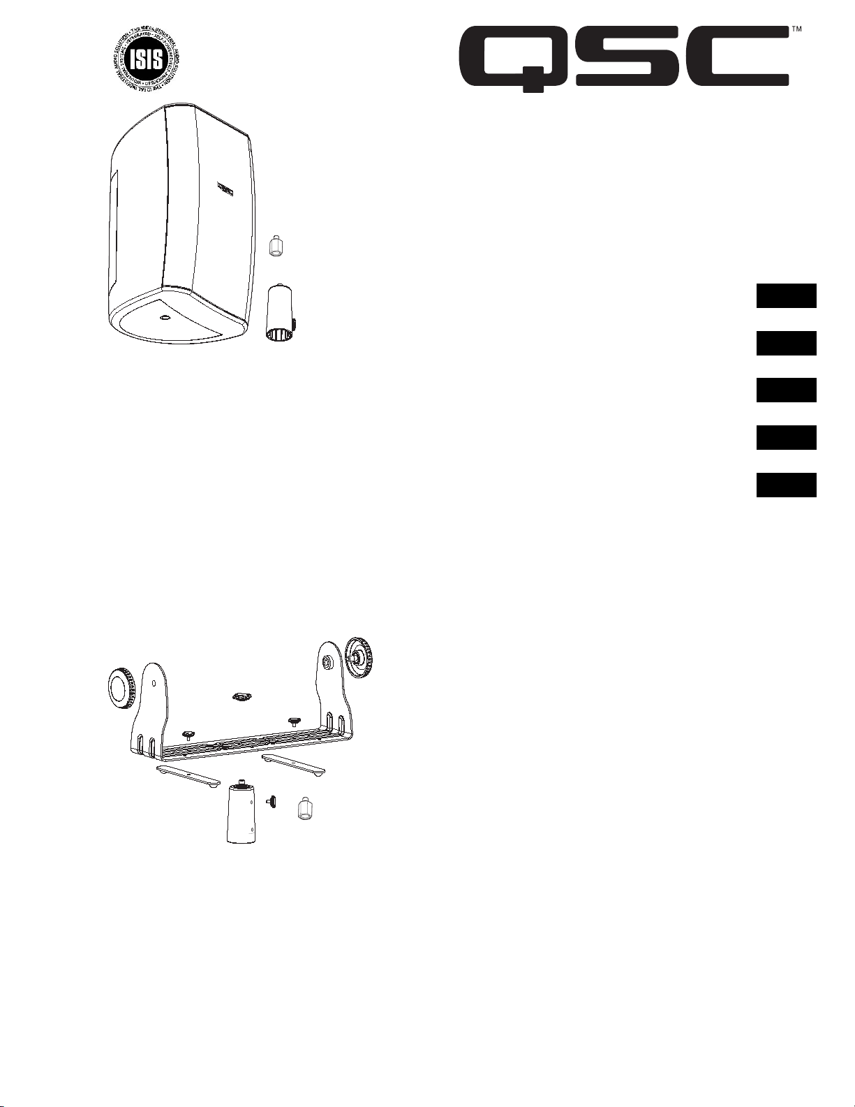
ISIS Series High Performance Portable Loudspeaker
Altavoz portátil de alto rendimiento serie ISIS
Haut-parleur portable haute performance série ISIS
Tragbarer High-Performance-Lautsprecher, Serie ISIS
ISIS ㋏߫催ᗻ㛑֓ᨎᓣᠽ䷇఼
I-82H
203 mm (8”) two-way
With Speakon® inputs,
pole cup and
mic stand adapter
203 mm (8") de dos vías
Con entradas Speakon®, conexión acopada para poste y adaptador para el soporte del micrófono
203 mm (8"), bidirectionnel
Avec entrées Speakon®, manchon de perche et adaptateur de pied de microphone
203 mm, Zwei-Weg
Mit Speakon® Eingängen, Stangenbuchse und Mikrofonständeradapter
203 mm (8”) ঠ
䜡᳝ Speakon® 䕧ܹˈᬃᴚᠬ呺ܟᬃᶊ䗖䜡఼
User Manual
Manual del usuario
Manuel d'utilisation
Benutzerhandbuch
⫼᠋ݠ
EN
ES
FR
DE
CH
I-YM8
Optional Accessory Kit
Multi-purpose yoke mount/ floor monitor hardware
Juego de accesorios opcionales
Montaje tipo horquilla multipropósito / herraje para el monitor de piso
Kit d'accessoires en option
Matériel de moniteur au sol/étrier de fixation polyvalent
Optionales Zubehörkit
Mehrzweck-Jochhalterung/Bodenmonitor-Befestigungsteile
ৃ䗝ᓣ䜡ӊㆅ
⫼䗨༫ᠬᶊ / ഄᵓⲥ㾚఼⹀ӊ
*TD-000140-00*
TD-000140-00 rev.B
EN
IMPORTANT SAFETY PRECAUTIONS
& EXPLANATION OF SYMBOLS
1- Read these instructions.
2- Keep these instructions.
3- Heed all warnings.
4- Follow all instructions.
5- Clean only with a dry cloth.
6- Install in accordance with QSC Audio Product’s instructions and a licensed, professional engineer.
7- Do not install near any heat sources such as radiators, heat registers, stoves, or other apparatus (including ampli-
fiers) that produce heat.
8- Only use attachments/accessories from QSC Audio Products, Inc.
9- Use only with mounts or brackets specified by QSC Audio Products.
10- Refer all servicing to qualified personnel. Servicing is required when the apparatus has been damaged in any
way.
The lightning flash with arrowhead symbol within an equilateral triangle is intended to alert the user to
the presence of uninsulated “dangerous” voltage within the product’s enclosure that may be of sufficient
magnitude to constitute a risk of electric shock to humans.
The exclamation point within an equilateral triangle is intended to alert the user to the presence of
important operating and maintenance (servicing) instructions in this manual.
WARNING! Before placing, installing, rigging, or suspending any speaker product, inspect all hardware,
suspension, cabinets, transducers, brackets and associated equipment for damage. Any missing, corroded, deformed or non-load rated component could significantly reduce the strength of the installation,
placement, or array. Any such condition severely reduces the safety of the installation and should be
immediately corrected. Use only hardware which is rated for the loading conditions of the installation
and any possible short-term unexpected overloading. Never exceed the rating of the hardware or equipment. Consult a licensed, professional engineer when any doubt or questions arise regarding a physical
equipment installation.
Warranty (USA only; other countries, see your dealer or distributor)
Disclaimer
QSC Audio Products, Inc. is not liable for any damage to amplifiers, or any other equipment that is caused by negligence or
improper installation and/or use of this loudspeaker product.
QSC Audio Products 3 Year Limited Warranty
QSC Audio Products, Inc. (“QSC”) guarantees its products to be free from defective material and / or workmanship for a period of
three (3) years from date of sale, and will replace defective parts and repair malfunctioning products under this warranty when the
defect occurs under normal installation and use - provided the unit is returned to our factory or one of our authorized service stations via pre-paid transportation with a copy of proof of purchase (i.e., sales receipt). This warranty provides that the examination
of the return product must indicate, in our judgment, a manufacturing defect. This warranty does not extend to any product which
has been subjected to misuse, neglect, accident, improper installation, or where the date code has been removed or defaced. QSC
shall not be liable for incidental and/or consequential damages. This warranty gives you specific legal rights. This limited warranty
is freely transferable during the term of the warranty period.
Customer may have additional rights, which vary from state to state.
In the event that this product was manufactured for export and sale outside of the United States or its territories, then this limited
warranty shall not apply. Removal of the serial number on this product, or purchase of this product from an unauthorized dealer,
will void this limited warranty.
Periodically, this warranty is updated. To obtain the most recent version of QSC’s warranty statement, please visit www.qscaudio.com.
Contact us at 800-854-4079 or visit our website at www.qscaudio.com.
© Copyright 2003, QSC Audio Products, Inc.
QSC® is a registered trademark of QSC Audio Products, Inc.
“QSC” and the QSC logo are registered with the U.S. Patent and Trademark Office
Speakon® is a registered trademark of Neutrik Inc. All trademarks are the property of their respective owners.
2
I-82H Introduction
Thank you and congratulations on your purchase of the ISIS Series
I-82H High Performance Portable Loudspeakers. This product represents the state-of-the-art in lightweight sound reinforcement
loudspeaker systems. To get the most from your investment, we
encourage you to review this manual carefully.
The I-82H loudspeaker system is a full range, high output, twoway design delivering superior sound quality and high SPL in a
lightweight, attractive enclosure. Equipped with two Speakon
connectors, connection is fast and reliable with parallel connection of multiple cabinets literally a snap. These loudspeakers
make an excellent choice for a wide variety of applications.
®
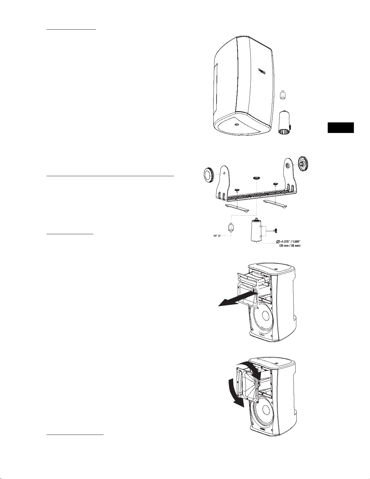
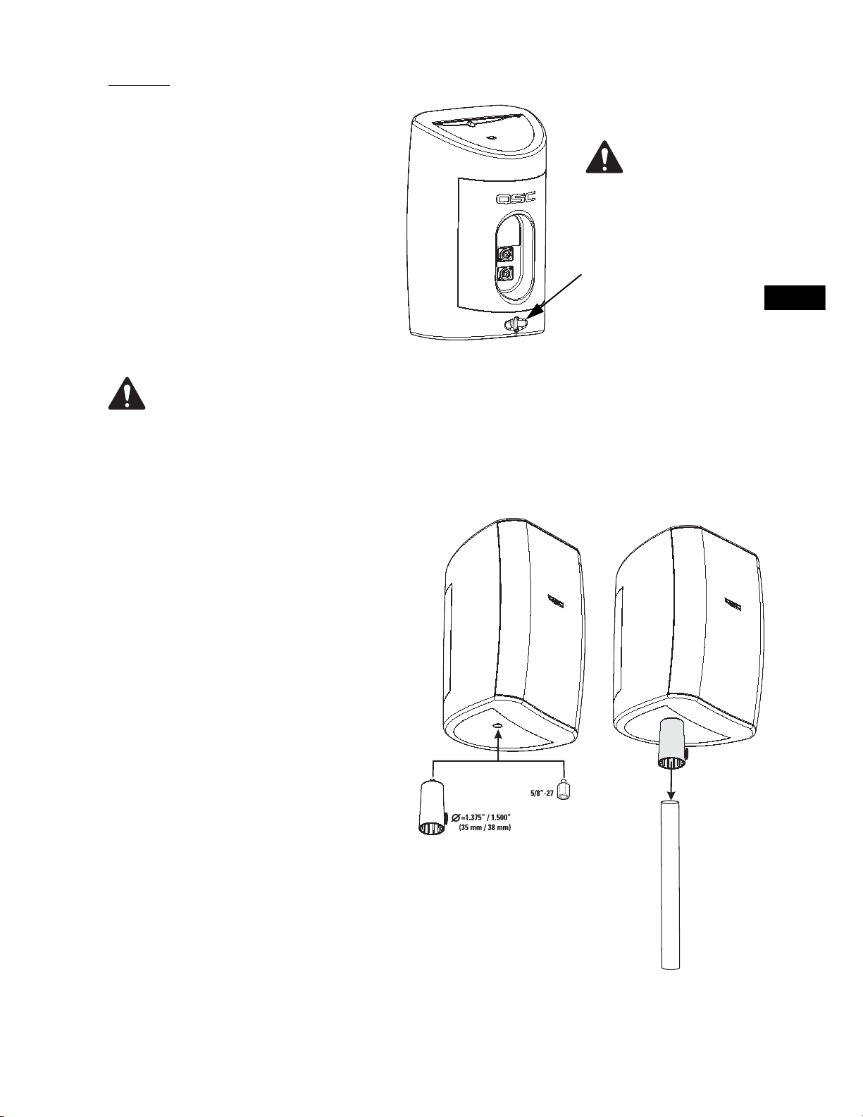
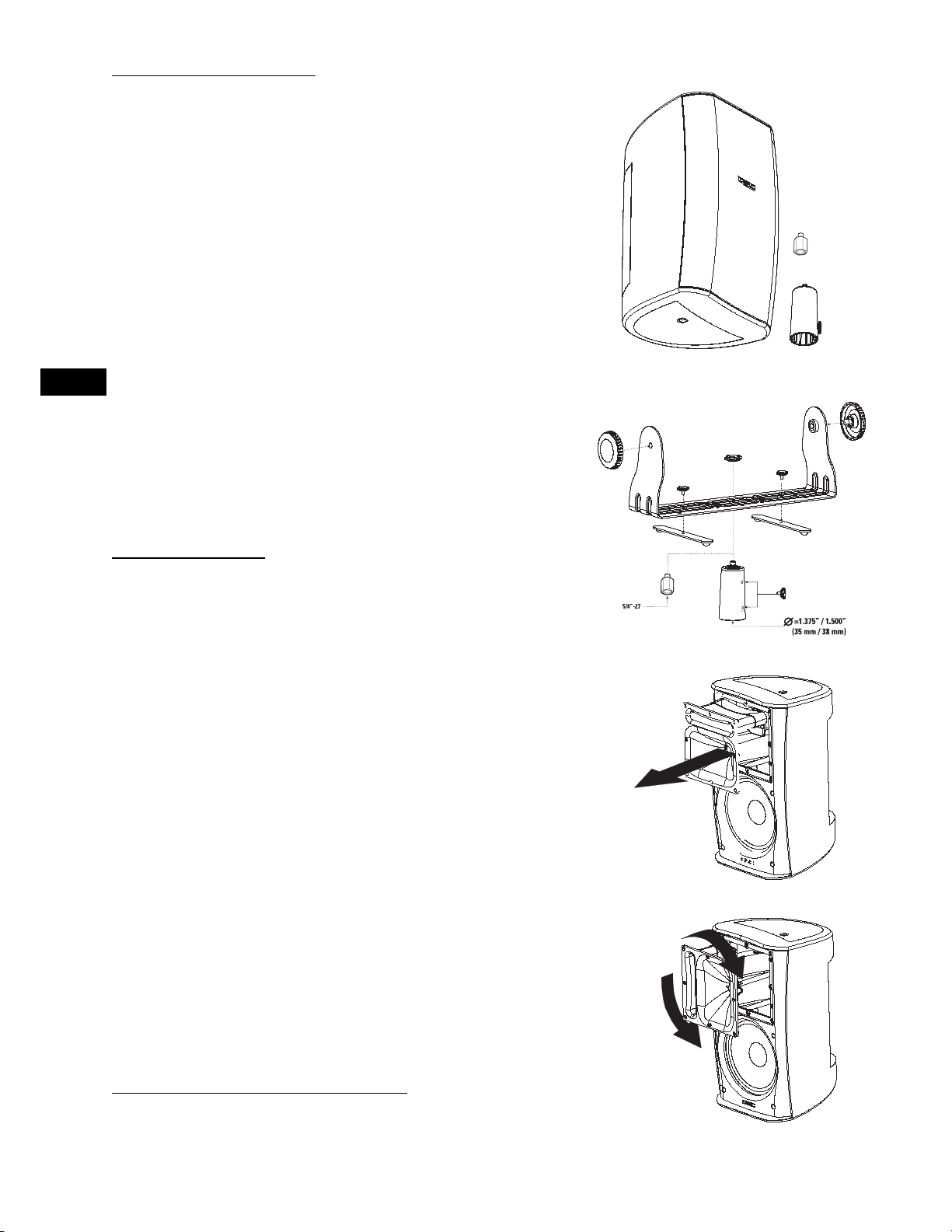
Two mounting adapters are provided; a pole cup that accepts
1.375” or 1.500” (35 mm or 38 mm) pole diameters and a 5/8”-27
mic stand adapter (fits most mic and boom stand hardware). The
pole cup is equipped with a retaining knob to secure the adapter
to the pole. Also included are four self-adhesive rubber feet for
the bottom of the enclosure.
I-YM8 Optional Yoke Mount / Floor Monitor Kit
The optional I-YM8 Accessory Kit provides a yoke mount suitable
for pole mounting and a pair of swivel extension feet for use as
floor or stage monitors. The included pole cup or mic stand
adapter can be attached to the yoke mount using the included
knob as well as standard truss clamps for additional mounting
options.
Coverage Angles
Before mounting the loudspeaker, determine the mounting orientation and desired coverage angles. As supplied from the factory,
the loudspeaker’s coverage angles are 90° (horizontal) x 60° (vertical) with the cabinet oriented vertically. The waveguide can be
rotated to interchange the coverage angles.
Rotating the Waveguide to Alter HF Coverage Pattern
1- Remove the grill. Gently and evenly work the grill out of its
retaining groove to avoid bending the grill.
EN
2- Remove the eight waveguide retaining screws. A #2-size Phillips screwdriver is recommended.
3- Reach into the waveguide’s port and pull gently to remove the
waveguide. Be careful not to damage the connections, wiring, or
the gasket between the waveguide and the cabinet.
4- Rotate the horn 90° clockwise or counter clockwise and set it
back in place. Make certain the wiring is not stressed or pulled
loose from its connections.
5- Before reinstalling the waveguide screws, lift the assembly a
small distance and make sure that the gasket is properly in place.
Reposition it, if required. Set the waveguide in place and reinstall
the screws. Do not overtighten.
6- Replace the grill.
Logo Badge Rotation
The logo badge on the grill screen can be removed, rotated, and
reinstalled. Using your fingers, pull the logo badge straight out.
Rotate to the desired position and push back into place.
3
EN
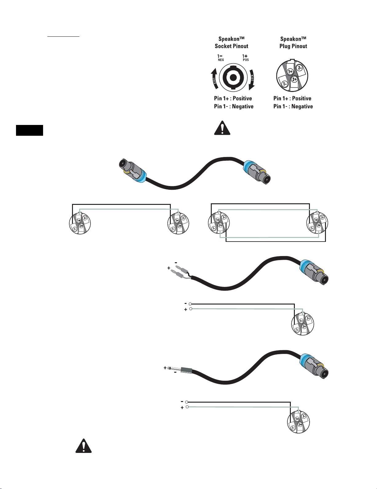
Connection
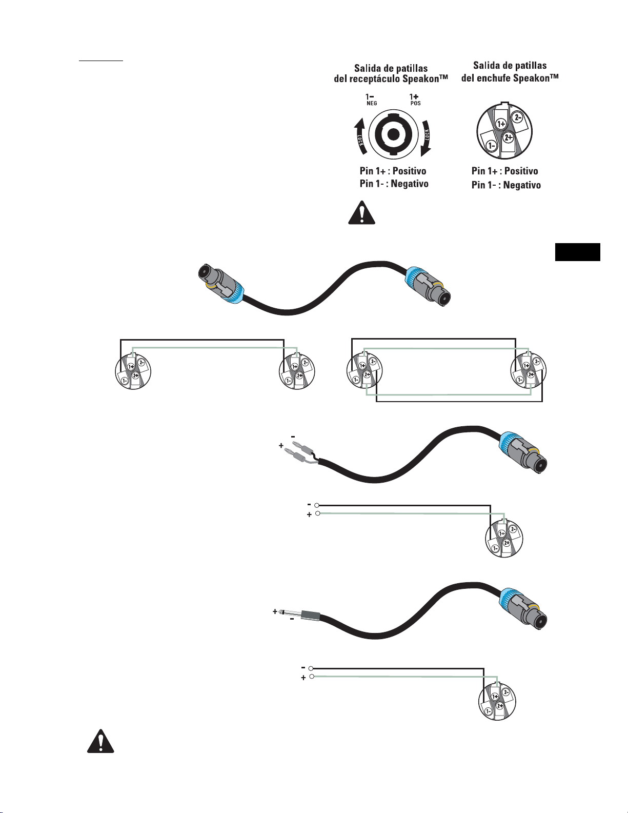
The I-82H has two Speakon® NL4-type connectors wired for full
range, passive operation. Connect the amplifier’s + and - outputs
directly to the Speakon’s 1+ and 1- terminals.
The two connectors are wired in parallel to make parallel cabinet
connection easy. Your amplifier must be able to safely power the
lower impedance of parallel-connected loudspeakers.
NL4 to NL4 Wiring (two- and four-conductor cables)
Two- or four-conductor cable may be used for Speakon to Speakon
connections. Four-conductor cable can be used, but the extra conductors do not carry signal.
The I-82H is not wired for biamp operation. Do not connect biamplified
equipment to the I-82H.
To Amplifier
Banana to NL4 Wiring
To Amplifier
To Loudspeaker
To Loudspeaker
1/4” Phone to NL4
To Amplifier
Maintain proper speaker and amplifier connection polarity throughout the entire system. All
positive-marked loudspeaker terminals should be connected to positive-marked amplifier
output terminals. This will provide the best possible low-frequency output from your system.
4
To Loudspeaker
Mounting
Stand Alone Mounting
If using the loudspeaker only, it can be set on any
appropriate surface. The cabinet will lean back at a
slight angle when set on a flat surface. Install the
four self-adhesive rubber feet on the cabinet bottom
to stabilize the loudspeaker and to help prevent it
from moving due to cabinet vibration at high output
levels.
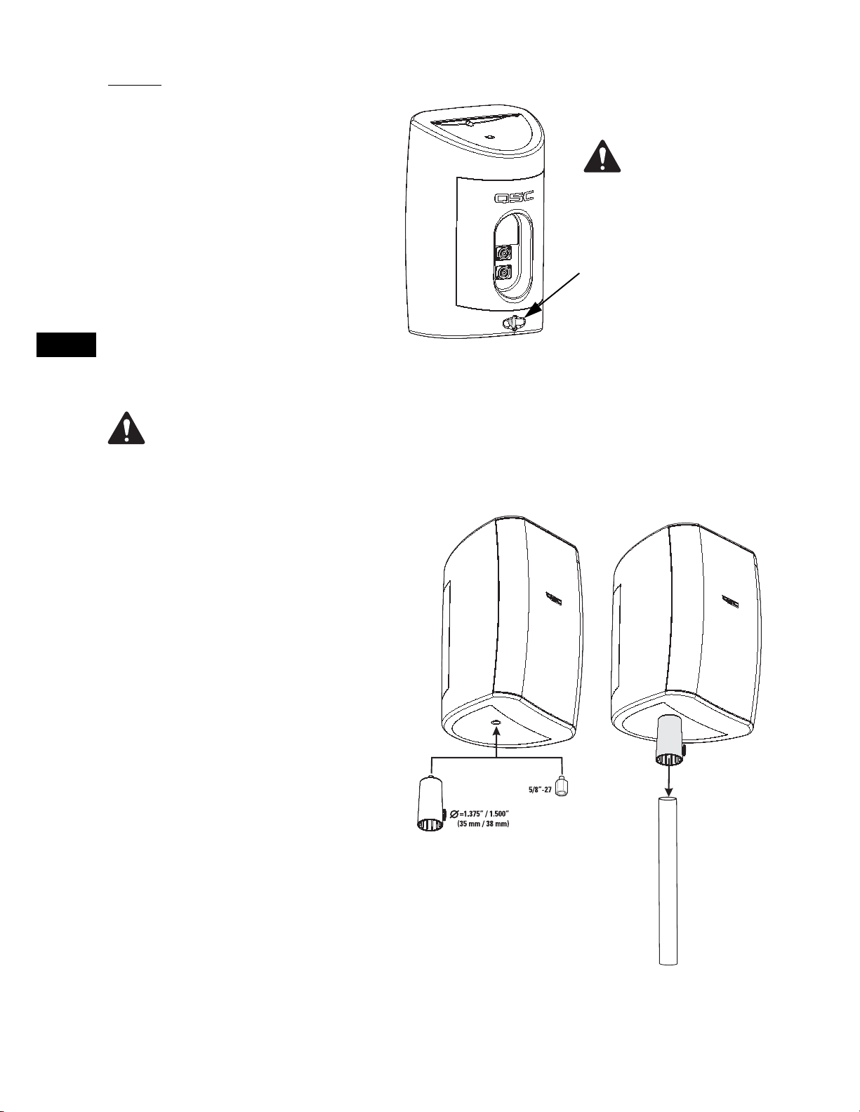
On the back of the loudspeaker, near the bottom, is
a safety cable attachment point. Install a safety
cable strong enough to support several times the
weight of the loudspeaker assembly in the event it
may fall. The cable must be secured to a secondary
support point which is also strong enough to support several times the loudspeaker’s weight.
IMPORTANT! ENSURE THAT THE
LOUDSPEAKER IS MOUNTED PROPERLY AND A SAFETY CABLE IS
INSTALLED TO RETAIN THE LOUDSPEAKER IN THE EVENT OF A MOUNTING FAILURE.
Ensure the mounting
surface and support-
ing structure are
appropriately strong enough to
support the loudspeaker
assembly and any potential
vibration or seismic activity.
Attach a safety cable to the
attachment point on the bottom-back of the loudspeaker.
Ensure the safety cable, cable
attachment technique, securing hardware, and attachment
points are strong enough to
support several times the
weight of the loudspeaker in
the event of a primary-mount
failure.
EN
Pole Cup
The included pole cup will fit 1.375” and 1.500” (35
and 38 mm) diameter poles. To use the pole cup,
thread the adapter into the insert on the bottom of
the loudspeaker. Ensure the adapter is secure
before mounting on pole. Set the pole cup onto the
pole and make sure the pole seats fully into the
adapter. 1.500” (38 mm) poles will seat about 2” (50
mm) deep in the adapter, and 1.375” (35 mm) poles
will seat about 4” (100 mm) deep in the adapter.
Make sure the set screw retaining knob is in the
correct hole for the pole size used and that it is
tightened.
5/8”-27 Mic Stand Adapter
The mic stand adapter is intended for use with
large-base tripod microphone stands.
5
EN
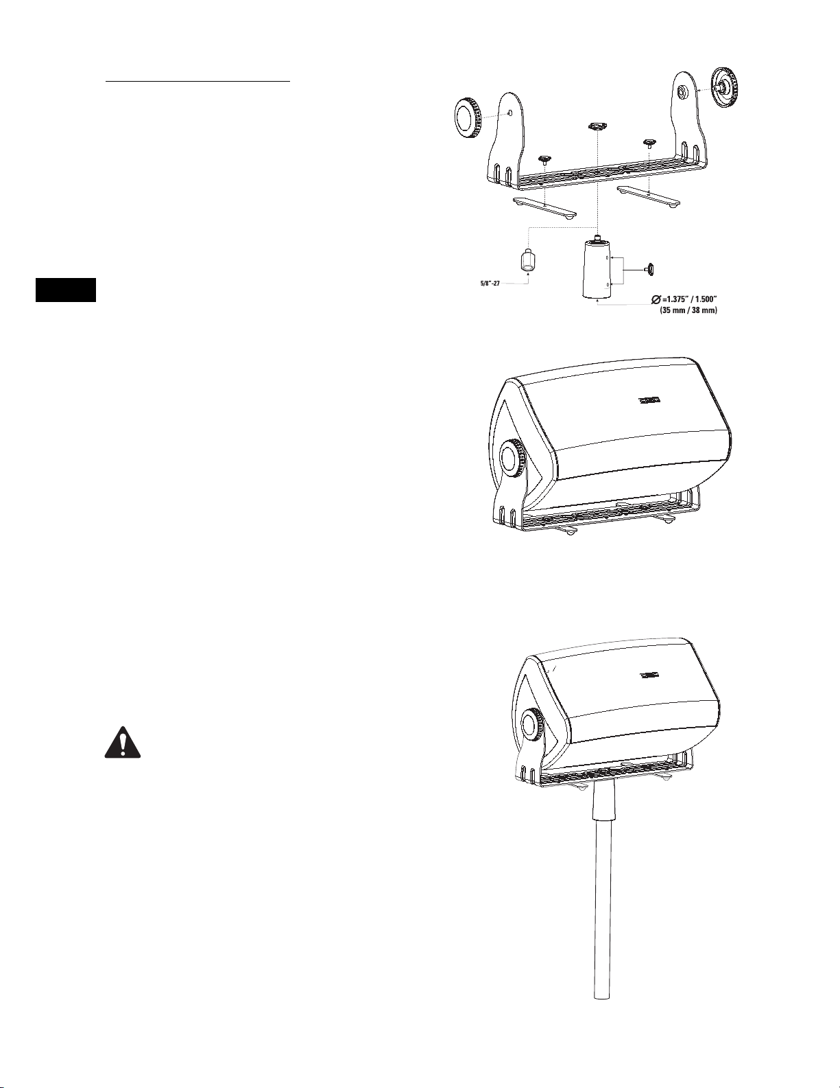
Optional I-YM8 Accessory Kit
The I-YM8 Accessory Kit includes a yoke mount bracket, two loudspeaker retaining knobs, two swivel feet with retaining knobs,
mic stand adapter, pole cup and retaining knob.
The I-YM8 Accessory Kit enables you to mount the loudspeaker to
most any surface using the yoke mount bracket, or use as a floor
monitor by attaching the two swivel feet. If wall mounting the
yoke, we recommend removing the swivel feet. The yoke mount
bracket may be attached to the pole cup, mic stand adapter, or a
standard truss clamp.
Floor Monitor Use
Attach the two swivel feet using the retaining knobs provided.
Use any of the holes along the centerline of the bracket, one
toward each end. Rotate the feet into place and tighten the knobs
to prevent rattling. Attach the loudspeaker and secure in place
with the large retaining knobs.
Pole Cup Use
For pole cup use, attach the pole cup to the yoke mount bracket.
Use the intermediate-sized retaining knob to secure the adapter
to the yoke using the large hole in the center of the bracket.
Attach the loudspeaker and secure in place with the large retaining knobs. Make sure the swivel feet are tight or removed completely to prevent rattling.
IMPORTANT! ENSURE THE LOUDSPEAKER IS
MOUNTED PROPERLY AND A SAFETY CABLE IS
INSTALLED TO RETAIN THE LOUDSPEAKER IN THE
EVENT OF A MOUNTING FAILURE.
Ensure the mounting surface and supporting structure are strong enough to support the loudspeaker
assembly during any potential vibration or seismic
activity.
Attach a safety cable to the attachment point on the
bottom-back of the loudspeaker. Ensure the safety
cable, cable attachment technique, securing hardware, and attachment points are strong enough to
support several times the weight of the loudspeaker in the event of a primary-mount failure.
6
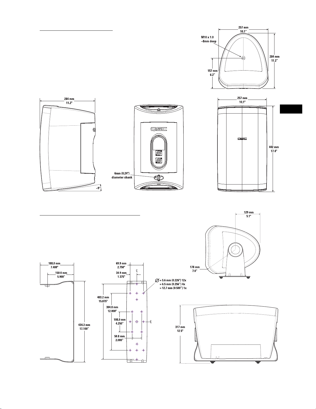
I-82H Loudspeaker Dimensions
EN
I-YM8 with I-82H Loudspeaker Dimensions
7

Specifications
Frequency Response1: 80- 21k Hz (-6 dB)
60- 22k Hz (-10 dB)
EN
Maximum Output
2
: 113 dB SPL continuous rms output
(calculated) 119 dB SPL peak output
Impedance: 8 ohms nominal
7.0 ohms minimum, 210 Hz
135 ohms maximum
Power Rating
3
:
rms (IEC 100 hrs): 200 watts rms
recommended amp power: 400 watts rms
Sensitivity: 90.5 dB, 1 watt, 1 meter, free field (4 pi)
Directivity Index: 500 Hz 4.0
1000 Hz 5.5
2000 Hz 11.7
4000 Hz 8.9
8000 Hz 8.6
16000 Hz 7.2
Q: 500 Hz 2.5
1000 Hz 3.6
2000 Hz 14.7
4000 Hz 7.7
8000 Hz 7.3
16000 Hz 5.3
Weight: I-82H: 17.5 lb. net, 20.5 lb. shipping
I-YM8: 2.8 lb. net, 5.0 lb. shipping
Nominal Coverage: 90° horiz. x 60° vert., waveguide can be rotated 90°
Enclosure and Grill: high impact polystyrene, removable metal grill, logo badge can be rotated
Connectors: two (2) Neutrik Speakon NL4FC connectors wired in parallel, +signal: pin 1+, - signal: pin 1-
Mounting Hardware: Included: Pole cup (attaches to loudspeaker bottom or optional yoke mount,
fits 1.375” or 1.500” (35 mm or 38 mm) diameter poles) and 5/8”-27 mic stand adapter.
Optional: Yoke mount with retaining knobs, two swivel feet for using yoke mount as stage
monitor, pole cup (attaches to loudspeaker bottom or optional yoke mount, fits 1.375” or 1.500”
(35 mm or 38 mm) diameter poles) and 5/8”-27 mic stand adapter, and retaining knob for pole cup.
NOTES:
1- All frequency ranges specified refer to measured free-field response (4 pi).
2- Calculated maximum peak SPL at 1 m, free-field, speaker operating at rated rms power pink noise input, 50 Hz to 20 kHz.
3- Maximum input power tested in accordance with IEC recommendations; 50 Hz to 20 kHz band limiting, 6 dB signal crest factor.
Specifications are subject to change without notice.
8
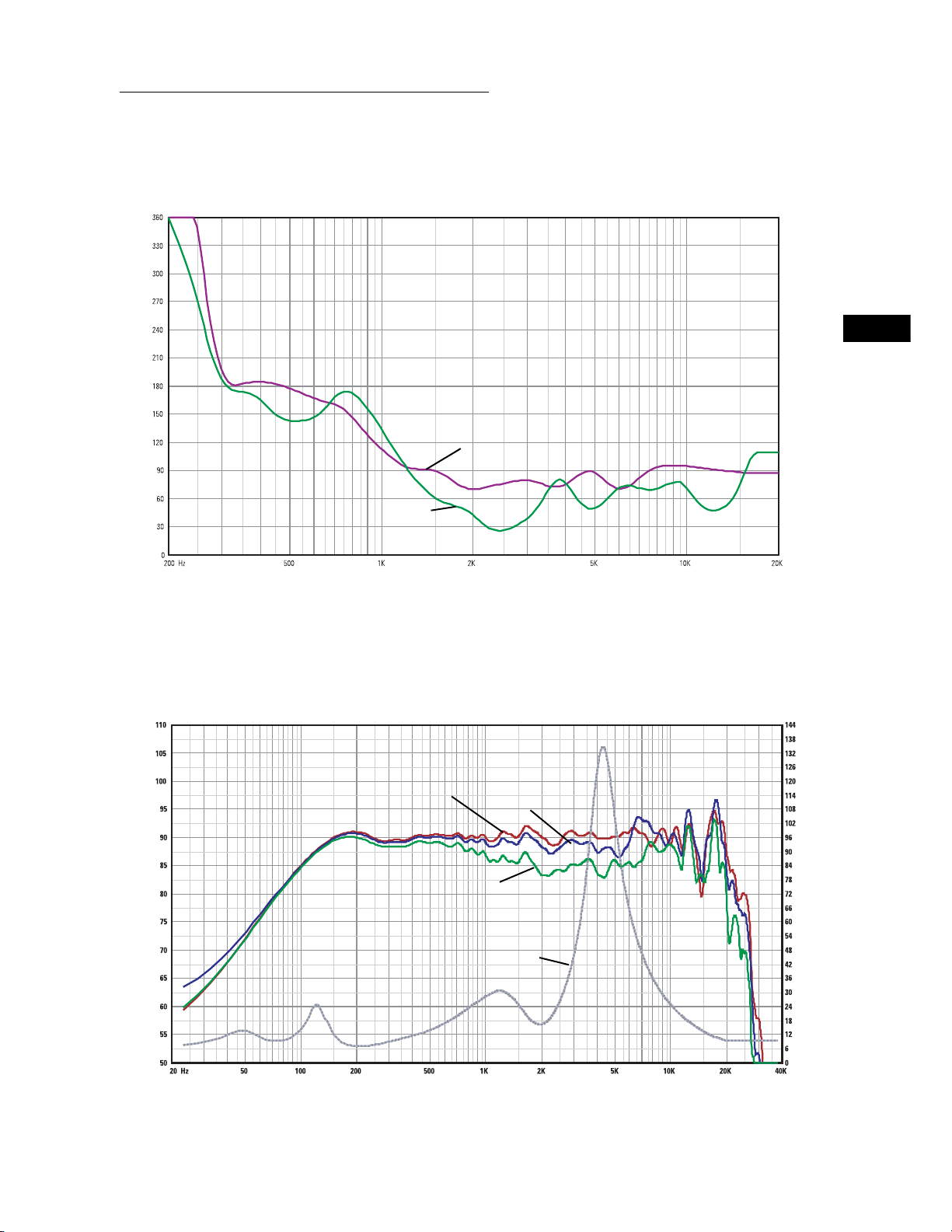
I-82H Beamwidth, Response, and Impedance Curves
I-82H Horizontal and Vertical Beamwidth Vs. Frequency
EN
Beamwidth (degrees)SPL (dB)
Horizontal
Vertical
Frequency (Hertz)
I-82H Response On-Axis, 20° Off-Axis, 40° Off-Axis, and Impedance Vs. Frequency
On Axis
20° Off Axis
40° Off Axis
Impedance
Frequency (Hertz)
Specifications are subject to change without notice.
Impedance (ohms)
9

EN
Painting the I-82H Loudspeaker
The loudspeaker enclosure, grill, and mount can be painted to match any decor, provided the following precautions are observed.
The cabinet is made of high impact polystyrene which requires controlled painting procedures in order to obtain good results. Use a
paint “system” designed for high impact polystyrene from any reputable paint supplier.
1- Remove the grill.
2- If painting mount and loudspeaker as a unit: Attach the I-YM8.
3- Mask the loudspeaker’s input connector.
4- Mask the woofer, tweeter, and port being certain not to apply tape directly to the drivers. Alternatively, the inside of the grill can
be completely masked and set in place on the loudspeaker enclosure for painting.
5- Wash the components to be painted with a mild soap and hot water. Be careful not to get water on or into either of the drivers or
the input connections. Rinse with hot water. Allow to dry thoroughly.
6- Scuff-sand the components to be painted using red Scotchbrite® pad or 320 - 400 grit sandpaper.
7- Using compressed air, remove all dust from the components to be painted. Do not blow compressed air directly into either driver.
8- Clean the components to be painted.
9- Using a clean, lint-free, white cloth, wipe the components to be painted with suitable prep solution.
10- Apply adhesion promoter.
11- Apply primer topcoat.
12- Apply paint.
13- Allow to dry for at least 8 hours before handling.
10
IMPORTANTES PRECAUCIONES DE SEGURIDAD Y EXPLICACIÓN DE LOS SÍMBOLOS
1- Lea estas instrucciones.
2- Conserve estas instrucciones.
3- Observe todas las advertencias.
4- Siga todas las instrucciones.
5- Limpie solamente con un paño seco.
6- Instale de acuerdo con las instrucciones de QSC Audio Product y de un ingeniero profesional licenciado.
7- No instale cerca de ninguna fuente de calor tal como radiadores, registros de calor, estufas u otros aparatos (inclusive
amplificadores) que produzcan calor.
8- Use solamente conectadores y accesorios de QSC Audio Products, Inc.
9- Use solo con montajes o soportes especificados por QSC Audio Products.
10- Refiera todo el servicio al personal calificado. Se requiere servicio cuando el aparato haya sido dañado de alguna manera.
El símbolo de un rayo con punta de flecha dentro de un triángulo equilátero tiene el propósito de alertar al usuario
de la presencia de voltaje "peligroso" no aislado dentro de la caja del producto, que puede ser de suficiente magnitud para constituir un riesgo de descarga eléctrica a los seres humanos.
Este signo de exclamación dentro de un triángulo equilátero tiene el propósito de alertar al usuario de la existencia
de importantes instrucciones de operación y mantenimiento (servicio) en este manual.
¡ADVERTENCIA! Antes de colocar, instalar, equipar o suspender cualquier altavoz, inspeccione todo el herraje, suspensión, gabinetes, transductores, soportes y equipo asociado para asegurarse de que estén en buenas condiciones. Todo componente faltante, corroído, deformado o clasificado sin carga podría reducir significativamente la
resistencia de la instalación, colocación o disposición. Cualquiera de tales condiciones reduce gravemente la seguridad de la instalación y se debe corregir inmediatamente. Use sólo herraje que esté clasificado para las condiciones de carga de la instalación y para cualquier posible sobrecarga a corto plazo inesperada. Nunca exceda la
capacidad nominal del herraje ni del equipo. Consulte a un ingeniero profesional licenciado cuando tenga dudas o
preguntas referentes a la instalación física del equipo.
Garantía (sólo EE.UU.; consulte a su concesionario o distribuidor si desea información para otros países)
Liberación de responsabilidad
QSC Audio Products, Inc. no es responsable por ningún daño a los amplificadores, o a cualquier otro equipo, que sea causado por negligencia o por instalación y/o uso inadecuado de este altavoz.
Garantía limitada de 3 años de QSC Audio Products
QSC Audio Products, Inc. ("QSC") garantiza que sus productos estarán libres de materiales y mano de obra defectuosos durante un período
de tres (3) años a partir de la fecha de la venta, y que reemplazará las piezas defectuosas y reparará los productos que no funcionen bien
bajo esta garantía, cuando el defecto ocurra bajo condiciones normales de instalación y uso, siempre y cuando la unidad se devuelva a
nuestra fábrica o a una de nuestras estaciones autorizadas de servicio mediante transportación pre-pagada con una copia del comprobante de compras (esto es, el recibo de la compra). Esta garantía dispone que el examen del producto devuelto debe indicar, a nuestro criterio, un defecto de fabricación. Esta garantía no se extiende a ningún producto que haya estado sujeto a uso inadecuado, negligencia,
accidente, instalación incorrecta o cuando el código de la fecha se haya removido o alterado. QSC no será responsable por daños incidentales o resultantes. Esta garantía le da derechos legales específicos. Esta garantía limitada se puede transferir libremente durante su
período de vigencia.
ES
El cliente puede tener otros derechos, que pueden variar entre estados.
En el evento que este producto se haya fabricado para su exportación y venta fuera de Estados Unidos o de sus territorios, esta garantía
limitada no será válida. La remoción del número de serie de este producto, o la compra de este producto a un concesionario no autorizado,
anulará esta garantía limitada.
Periódicamente se actualiza esta garantía. Para obtener la versión más reciente de la declaración de la garantía de QSC, por favor visite
www.qscaudio.com.
Comuníquese con nosotros al teléfono 800-854-4079 o visite nuestro sitio en la Web en www.qscaudio.com.
© Copyright 2003, QSC Audio Products, Inc.
QSC® es una marca registrada de QSC Audio Products, Inc.
"QSC" y el logotipo de QSC están registrados con la Oficina de Patentes y Marcas Comerciales de EE.UU.
Speakon® es una marca registrada de Neutrik Inc. Todas las marcas comerciales son propiedad de sus respectivos propietarios.
11
ES
Introducción al altavoz I-82H
Le agradecemos y felicitamos por su adquisición de los altavoces portátiles de alto rendimiento I-82H serie ISIS. Este producto representa lo más avanzado en sistemas de
altavoces ligeros con refuerzo sonoro. Para aprovechar al máximo su inversión, le
recomendamos que revise detenidamente este manual.
El sistema de altavoces I-82H tiene un diseño de amplitud completa, alta salida, de dos
vías que produce un sonido de calidad superior y un alto nivel de presión sonora (SPL)
en una caja ligera y atractiva. Equipado con dos conectadores Speakon®, la conexión
es rápida y fiable, permitiendo conectar en paralelo múltiples armarios en un abrir y
cerrar de ojos. Estos altavoces son una opción excelente para una amplia variedad de
aplicaciones.
Se suministran dos adaptadores de montaje; una conexión acopada para poste que
acepta diámetros de poste de 1,375 pulgadas o 1,500 pulgadas (35 mm o 38 mm) y un
adaptador para el soporte del micrófono de 5/8"-27 (sirve para la mayor parte del herraje de soporte para micrófonos y pértigas). La conexión acopada para poste está equipada con una perilla de retención que permite fijar el adaptador al poste. También se
incluyen cuatro patas de caucho autoadhesivo para la parte inferior de la caja.
Juego opcional de montaje tipo horquilla / monitor de piso I-YM8
El juego opcional de accesorios I-YM8 proporciona un montaje tipo horquilla apropiado
para montar en poste, además de un par de patas de extensión giratorias para uso
como monitores de piso o escenario. La conexión acopada para poste o adaptador para
soporte del micrófono, incluidos, se pueden conectar al montaje tipo horquilla usando
la perilla incluida, así como abrazaderas de armadura estándar para permitir opciones
adicionales de montaje.
Ángulos de cobertura
Antes de montar el altavoz, determine la orientación del montaje y los ángulos de
cobertura deseados. Al salir de la fábrica los altavoces tienen ángulos de cobertura de
90º (horizontal) x 60º (vertical) con el gabinete orientado verticalmente. El guíaondas se
puede rotar para intercambiar los ángulos de cobertura.
Rotación del guíaondas para alterar el patrón de cobertura de alta frecuencia
1- Retire la parrilla. Suavemente y de manera uniforme saque la parrilla de su ranura de
retención para evitar doblarla.
2- Quite los ocho tornillos de retención del guíaondas. Se recomienda usar un destornillador Phillips N.º 2.
3- Sujete el puerto del guíaondas y hale suavemente para sacar el guíaondas. Tenga
cuidado de no dañar las conexiones, el cableado o la junta que se encuentra entre el
guíaondas y el gabinete.
4- Gire la bocina 90° hacia la derecha o hacia la izquierda y vuélvala a colocar en su
lugar. Asegúrese de no ejercer tensión sobre el cableado ni desconectarlo.
5- Antes de instalar los tornillos del guíaondas, levante un poco el conjunto y asegúrese de que la junta esté adecuadamente instalada. Ajuste su posición si es necesario. Coloque el guíaondas en su lugar y vuelva a colocar los tornillos. No los apriete
excesivamente.
6- Vuelva a instalar la parrilla.
Rotación del identificador con el logotipo
El identificador con el logotipo en la pantalla tipo parrilla se puede desmontar, girar y
volver a instalar. Utilice sus dedos para halar del identificador con el logotipo, para
quitarlo. Gire hasta la posición deseada y vuelva a colocarlo en posición.
Rotación del identificador con el logotipo
El identificador con el logotipo en la pantalla tipo parrilla se puede desmontar, girar y
volver a instalar. Utilice sus dedos para halar del identificador con el logotipo, para
quitarlo. Gire hasta la posición deseada y vuelva a colocarlo en posición.
12
Conexión
El altavoz I-82H tiene dos conectores Speakon® tipo NL4 cableados para brindar una operación pasiva de rango completo.
Conecte las salidas + y - del amplificador directamente en los terminales 1+ y 1- del conector Speakon.
Los dos conectores están cableados en paralelo para facilitar las
conexiones en paralelo al armario. El amplificador debe tener
potencia suficiente para afrontar la menor impedancia de los
altavoces conectados en paralelo.
Cableado NL4 a NL4 (cables de dos y cuatro conductores)
Se puede usar un cable de dos o cuatro conductores para realizar
las conexiones de un conectador Speakon a otro. Se puede utilizar
un cable de cuatro conductores; sin embargo, los conductores adicionales no transportan señal alguna.
Al amplificador
El altavoz I-82H no está cableado para
operación biamplificada. No conecte
equipos biamplificado al altavoz I-82H.
ES
Al altavoz
Cableado de conectores tipo banana a NL4
Conector telefónico de 1/4" a NL4
Al amplificador
Al amplificador
Al altavoz
Al altavoz
Mantenga la polaridad adecuada en las conexiones del altavoz y el amplificador en todo el sistema. Todos los
terminales con signo positivo del altavoz se deben conectar con los terminales de salida con signo positivo
del amplificador. Esto proporcionará la mejor salida de baja frecuencia posible de su sistema.
13
Montaje
Montaje autónomo
Si está usando únicamente el altavoz, podrá colocarlo
sobre cualquier superficie apropiada. Cuando se
coloque sobre una superficie plana el gabinete quedará inclinado a un ligero ángulo. Instale las cuatro
patas de caucho autoadhesivo en la parte inferior del
armario para estabilizar el altavoz y ayudar a evitar su
desplazamiento como consecuencia de las vibraciones
del armario a altos niveles de salida.
Asegúrese de que la
superficie de montaje y la
estructura de apoyo sean
lo suficientemente fuertes para
soportar el conjunto del altavoz y
cualquier vibración potencial o
actividad sísmica.
ES
En la parte posterior del altavoz, cerca del fondo, hay
un punto de conexión para un cable de seguridad.
Instale un cable de seguridad suficientemente fuerte
que soporte varias veces el peso del conjunto del
altavoz en caso de que se caiga. El cable debe estar
asegurado a un punto de apoyo secundario que también sea lo suficientemente fuerte como para soportar
varias veces el peso del altavoz.
¡IMPORTANTE! ASEGÚRESE DE QUE EL
ALTAVOZ ESTÉ MONTADO ADECUADAMENTE Y QUE SE HAYA INSTALADO UN
CABLE DE SEGURIDAD QUE DETENGA AL
ALTAVOZ EN CASO DE UNA FALLA EN EL
MONTAJE.
Conexión acopada para poste
La conexión acopada para poste incluida se adapta a
postes de 1,375 pulgadas y 1,500 pulgadas (35 y 38
mm) de diámetro. Para utilizar la conexión acopada
para poste, enrosque el adaptador sobre el inserto en
la parte inferior del altavoz. Asegúrese de que el
adaptador esté firme antes de montarlo en un poste.
Coloque la conexión acopada sobre el poste y asegúrese de que el poste se asiente completamente en el
adaptador. Los postes de 1,500 pulgadas (38 mm) se
asentará a una profundidad de aproximadamente 2
pulgadas (50 mm) en el adaptador, mientras que los
postes de 1,375 pulgadas (35 mm) se asentarán a
aproximadamente 4 pulgadas (100 mm) de profundidad en el adaptador. Asegúrese de que la perilla de
retención del tornillo de fijación esté en el orificio correcto para el tamaño del poste empleado, y que esté
bien apretado.
Conecte un cable de seguridad en
el punto de conexión que se
encuentra en la parte posterior
inferior del altavoz. Asegúrese de
que el cable de seguridad, la técnica usada para conectarlo, el
herraje de fijación y los puntos de
conexión sean lo suficientemente
fuertes como para soportar varias
veces el peso del altavoz en caso
de una falla del montaje primario.
14
Adaptador para soportes de micrófono de 5/8"-27
El adaptador para soportes de micrófono sirve para
uso con soportes de micrófono tipo trípode de base
grande.
 Loading...