

QSC DCM-1, DCM-2 Owners manual
DCM Series
Digital Cinema Monitor & Crossover System
USER MANUAL
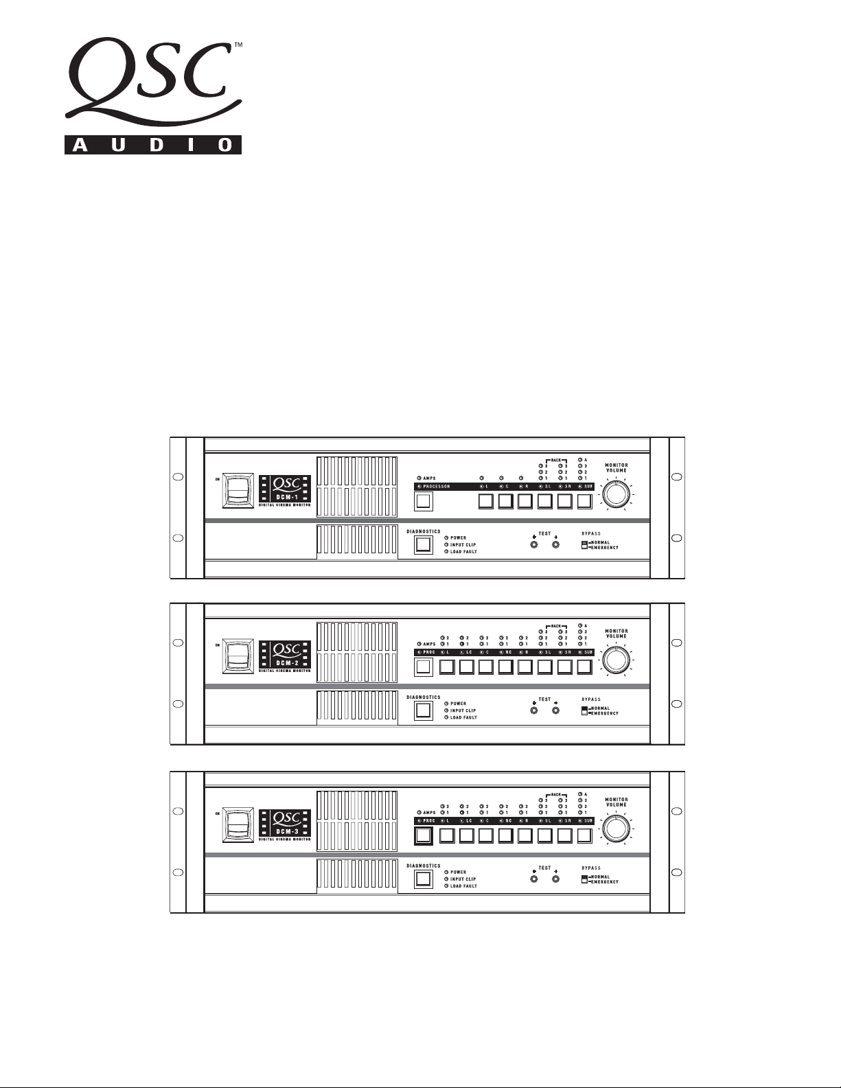
DCM-1
DCM-2
DCM-3
*TD-000106-00*
TD-000106-00 Rev.B
1
IMPORTANT SAFETY INSTRUCTIONS
& EXPLANATION OF SYMBOLS
1- Read these instructions.
2- Keep these instructions.
3- Heed all warnings.
4- Follow all instructions.
5- Do not use this apparatus near water.
6- Clean only with a dry cloth.
7- Do not block any ventilation openings. Install in accordance with QSC Audio Product’s instructions.
8- Do not install near any heat sources such as radiators, heat registers, stoves, or other apparatus (including
amplifiers) that produce heat.
9- Do not defeat the safety purpose of the polarized or grounding-type plug. A polarized plug has two blades with one
blade wider than the other. A grounding-type plug has two blades and a third grounding prong. The wide blade or the
third prong is provided for your safety. If the provided plug does not fit your outlet, consult an electrician for the
replacement of the obsolete outlet.
10- Protect the power cord from being walked on or pinched, particularly at plugs, convenience receptacles, and the
point where they exit the apparatus.
11- Only use attachments/accessories from QSC Audio Products, Inc.
12- Use only with carts, stands, tripods, brackets, interconnecting cables, or software specified by QSC Audio
Products. When moving or transporting using a cart, use caution to avoid injury from tip-over.
13- Unplug the apparatus during lightning storms or when unused for long periods of time.
14- Refer all servicing to qualified personnel. Servicing is required when the apparatus has been damaged in any way,
such as power supply cord or plug is damaged, liquid has been spilled or objects have fallen into the apparatus, the
apparatus has been exposed to rain or moisture, does not operate normally, or has been dropped.
15- When installing equipment into a rack, distribute the units evenly. Otherwise, hazardous conditions may be
created by an uneven weight distribution.
16- Connect the unit only to a properly rated supply circuit.
17- Reliable earthing (grounding) of rack-mounted equipment should be maintained.
18- Maximum operating ambient temperature is 50°C.
The lightning flash with arrowhead symbol within an equilateral triangle is intended to alert
the user to the presence of uninsulated “dangerous” voltage within the product’s enclosure
that may be of sufficient magnitude to constitute a risk of electric shock to humans.
The exclamation point within an equilateral triangle is intended to alert the user to the presence of important operating and maintenance (servicing) instructions in this manual.
CAUTION: To reduce the risk of electric shock, do not
CAUTION
RISK OF ELECTRIC SHOCK
DO NOT OPEN
remove the cover. No user-serviceable parts inside.
Refer servicing to qualified service personnel.
WARNING: To prevent fire or electric shock, do not
expose this equipment to rain or moisture.
FEDERAL COMMUNICATIONS COMMISSION (FCC) INFORMATION
NOTE: This equipment has been tested and found to comply with the limits for a Class A digital device, pursuant to Part 15 of the FCC Rules. These limits
are designed to provide reasonable protection against harmful interference in a commercial installation. This equipment generates, uses, and can radiate
radio frequency energy and, if not installed and used in accordance with the instructions, may cause harmful interference to radio communications.
Operation of this equipment in a residential area is likely to cause harmful interference, in which case the user will be required to correct the interference
at his or her own expense.
© Copyright 2002, QSC Audio Products, Inc.
“QSC” and the QSC logo are registered with the U.S. Patent and Trademark Office
QSC® is a registered trademark of QSC Audio Products, Inc.
2

CONTENTS
Introduction........................................................4
System Requirements......................................................5
Unpacking......................................................................5
System Concepts................................................................6
Illustrations................................................................8
Hardware Description..............................................................11
Software Description.....................................................18
Installation............................................................19
Troubleshooting.............................................................29
Specifications.............................................................32
Warranty Information..........................................................34
The DCM hardware unit and DCM Manager software are the property of QSC Audio Inc. Information in this document is subject to change without notice and does
not represent a commitment on the part of QSC Audio. The software described here is furnished under a licensing agreement. It is against the law to copy the
software on any medium except as specifically allowed in the licensing agreement. DCM Manager is a trademark of QSC Audio Products, Inc; Windows and Windows
98, NT, XP and 2000 are trademarks of Microsoft Corporation; IBM is a registered trademark of IBM Corporation; Pentium is a registered trademark of Intel
Corporation. Copyright 2002 QSC Audio Inc. All rights reserved. Printed in USA. QSC Audio Products, Inc., Technical Document Number TD-000106-00.
3
INTRODUCTION
INTRODUCTION
Thank you and congratulations on your purchase of the QSC DCM Digital Cinema Monitor. This product
represents the state-of-the-art for cinema-based signal processing and monitoring functions in a single,
integrated system. Designed to compliment QSC’s DCA (Digital Cinema Amplifier) Series amplifier
products, the DCM optimizes loudspeaker performance while facilitating easy cinema sound system
wiring and configuration. To get the most from your investment, we encourage you to review this
manual carefully.
The QSC DCM provides a wealth of signal processing functions with the ability to copy and transfer
settings—resulting in fast system setup time in multiplex theaters where multiple rooms share similar
characteristics. Providing both monitor and crossover functions in a single unit, the DCM is capable of
simple crossover adjustments via a personal computer (PC). These modifications can be password
protected for tamper-proof system control.
Fast Setup with Easy Wiring
Your DCM takes advantage of the unique DataPort found on DCA Series amplifiers and thus greatly
simplifies system wiring—reducing installation and labor costs in the process. A single VGA-style cable
per amplifier contains two input signals, two return signals, power on/standby control, and two channels of load monitoring.
The included menu-driven, PC configuration software further enhances the DCM setup. This software
includes a database that lists the default parameters for popular cinema loudspeaker models. Commonly used configurations can be saved to disk, facilitating the easy transfer of settings to other DCMs.
Advanced Monitoring Control
In addition to the monitoring of your amplifier’s audio I/O, your DCM includes QSC’s exclusive “Load
Fault” detection feature. The DCM monitors for possible speaker system or wiring faults and notifies
you via LED Load Fault indicators.
4

SYSTEM REQUIREMENTS and UNPACKING
SYSTEM REQUIREMENTS
DCM Manager software is designed to control one DCM hardware unit at a time. To use this software
with the DCM hardware unit, you must have the following:
1- Digital Cinema Monitor unit
2- DCM Manager software installation CD
3- IBM-compatible PC with a 200 MHz Pentium processor (or better)
Windows 98, NT, XP, or 2000
Microsoft® Internet Explorer 4.0 (or later)
Minimum 16MB of RAM
Minimum 10MB of available hard disk storage space
CDROM drive
Display resolution of 800X600, 16 colors minimum
RS-232 serial port (COM port, 9-pin)
A standard DB9 RS-232 cable (male to female)
To complete your Cinema System, you will also need a cinema processor, QSC Audio’s DCA amplifiers,
speakers, and necessary cables.
UNPACKING
The DCM is highly durable and carefully packaged. We recommend you inspect the unit carefully after
removing it from the packaging, as occasionally there may be damage due to some unfortunate incident
during shipment. Report any damage to the shipping carrier. We recommend saving the carton and
packing material in case the unit must be shipped back to your dealer, distributor, or service center. Also
note: some freight companies consider damage claims without the original packing materials invalid.
The QSC shipping box should contain:
1- the DCM unit
2- this owner’s manual
3- four adhesive feet (for non-rack mounting installation)
4- AC power cord, IEC-type, 18 AWG, 6 feet long, 120V
5- warranty card
6- QSC store catalog
7- QSC accessories sheet
8- DCM Manager Application Disk
5

SYSTEM CONCEPTS
SYSTEM CONCEPTS
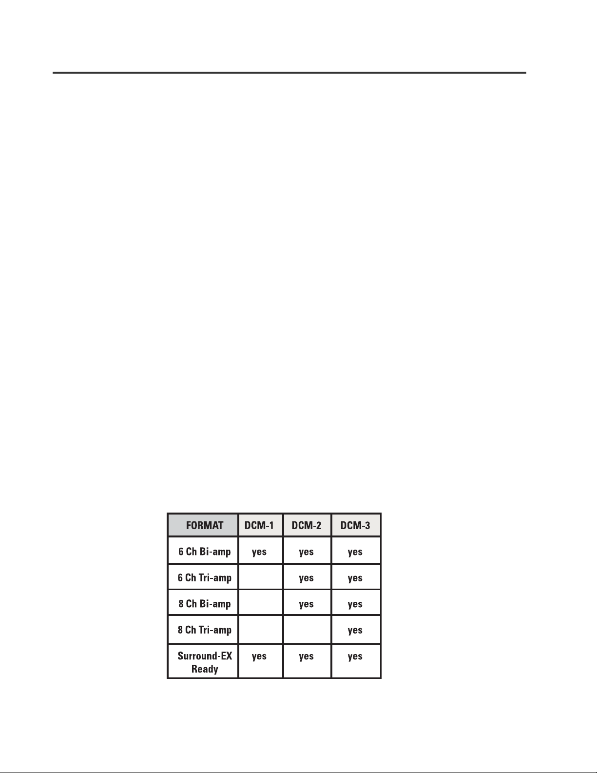
System Design Features
The DCM series Digital Cinema Monitor has many unique features which combine to make this the most
cost effective and versatile systems solution in the industry.
Installer Features:
•Provides Monitor and Crossover functions in one box.
•Minimizes the amount of cabling required. Only 1 cable per two-channel amplifier!
•Minimizes setup time, particularly in megaplexs with similar rooms.
•Provides speaker setting database for most common theater speaker brands and models.
•Indicates if something is wrong with the sound system and provides diagnostic feedback.
•Emergency bypass allows center channel sound to pass through even if there is a major problem.
•Allow easy routing and crossover adjustments.
•Protects system adjustments from tampering.
•Sound quality is state-of-the-art (high dynamic range).
Projectionist Features:
•Easy to verify all of the audio in the theater is okay.
•Automatic monitoring will light an LED if there is trouble with a speaker output.
•A backup system (emergency bypass) can be easily activated.
1. QSC Amplifier DataPorts: The DataPort
connectors reduce the complexity of wiring
between the DCM and the amplifiers. The
DataPort connections replace amplifier audio
input cables and amplifier output monitor
connections. Another unique feature of the QSC
Cinema System is the ability to automatically
analyze voltage and current on the amplifier’s
output terminals to determine shorts or opens in
the speaker cables or drivers. Each two-channel
amplifier is connected using one DataPort
cable. We recommend you use QSC DataPort
cables, but normal computer VGA cables will
work providing that all pins are terminated.
QSC’s Technical Services Group can supply
DataPort cables with high quality shielded
audio wires within the cable for maximum
interference protection on long runs or for
electrically-noisy environments.
2. Programmable processing and crossover settings: DCM processing is adjusted
using the DCM Manager software and the RS232 connection. Configuration files can be
saved and used for other DCMs. For example, if
a megaplex theater has several rooms with
similar size and equipment, a technician can
adjust one DCM unit for best results, and then
download all of these settings to other DCM
units. The functions that can be controlled
remotely are: crossover settings for screen
channel outputs, mutes, multiple equalizer
settings per channel, delay times, output
volume levels, monitor mix balance adjustments, and more.
6

SYSTEM CONCEPTS
3. DSP processing: Digital filtering of audio
signals is known to have several advantages
over analog solutions. DSP (digital signal
processor) IC chips allow extremely accurate
and reliable control of frequency and time
adjustments (boost, cut, cutoff frequency, delay
time), and stability (immunity from temperature
variations). The audio path of the DCM uses
conversion circuitry (changing the signal from
analog to digital and back again) which is
designed to minimize all background noise and
react to the dynamic range of any film track.
4. Speaker Database (pre-programmed
settings): QSC has worked with the leading
suppliers of theater speakers to obtain the
optimum settings for most common theater
speaker models. This database is easily loaded
into the DCM hardware unit and the DCM
Manager software offers features to organize,
store, and edit these settings. This feature
guarantees that your installation starts with
technically optimized settings before you begin
adjusting for room characteristics.
5. Fault Analysis: Each amplifier output
channel is compared to the corresponding input
signal providing complete signal path confirmation. For example, if there is signal at the DCM
input but there is no signal at the corresponding
amplifier output, then the fault indicator will
light. Additionally, if an amplifier output is
shorted or open, the fault indicator will light.
Pressing the Diagnostics button will indicate
which channel has this fault condition. Detailed
fault information can also be viewed using the
DCM Manager software.
6. Password Security: The crossover settings
that you create can make a dramatic difference
in the sound quality within the theater. Many
installers pride themselves on being able to
adjust the electrical parameters (crossover
points, equalization, delay, etc) to exactly
compliment the speaker and room interactions.
As such, their ability to set these parameters is
a “value added” service which deserves protection from competitors. We have therefore
included a security system where you can
protect your settings within the DCM from
being uploaded and copied by the DCM Manager software. Only your unique password will
allow viewing or editing of the crossover
settings. Should you forget your password, an
entirely new configuration can be loaded.
7. Emergency Bypass: If the DCM fails,
quickly getting a usable sound path is as easy
as flipping a switch. A front panel bypass
switch provides the projectionist a simple
Emergency Bypass. A passive crossover has
been built into the center channel routing so
that even with a total loss of power to the
DCM, a usable sound path will be maintained.
Activation of this bypass is done by the projectionist via a front panel Emergency Bypass
switch.
8. Surround Insert Connections: To accommodate multichannel surround, the surround
signals can be routed from the DCM to an
external processor box (such as a Dolby SA-10)
and back into the DCM for routing to the QSC
amplifiers.
7
ILLUSTRATIONS- DCM-1
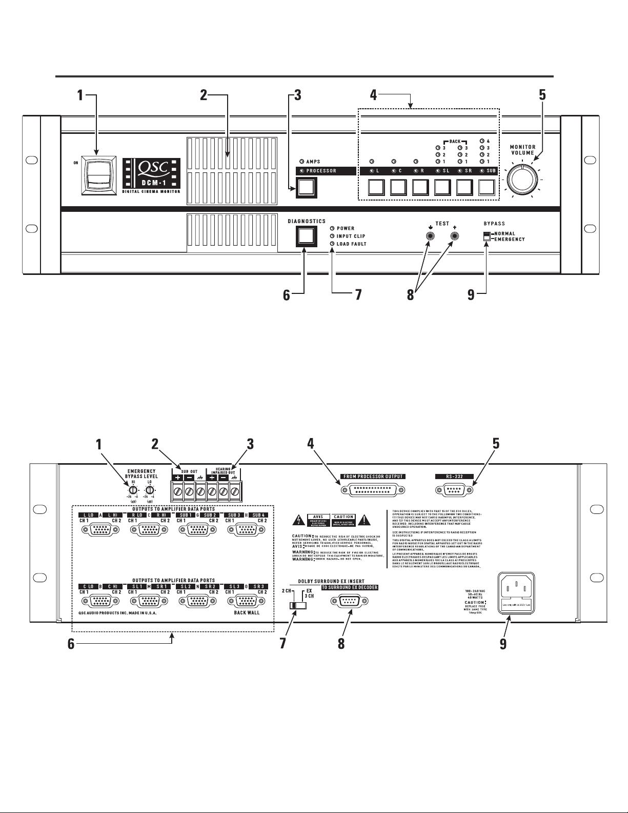
DCM-1 FRONT PANEL
1- Power switch
2- Monitor output speaker
3- Processor/Amps selector switch
4- Monitor source selector switches
5- Monitor volume control
6- Diagnostics check switch
7- Power “on” and diagnostics fault indicator LEDs
8- Monitor output test points
9- Bypass switch
DCM-1 REAR PANEL
1- Emergency bypass level controls
2- Subwoofer output
3- Hearing Impaired system output
4- Audio input connector (from Cinema Processor)
5- RS-232 port
8
6- DataPort outputs to amplifiers
7- Dolby Surround selector switch
8- Output to Dolby Surround EX decoder
9- IEC-style power cord entry and fuseholder

ILLUSTRATIONS- DCM-2
DCM-2 FRONT PANEL
1- Power switch
2- Monitor output speaker
3- Processor/Amps selector switch
4- Monitor source selector switches
5- Monitor volume control
6- Diagnostics check switch
7- Power “on” and diagnostics fault indicator LEDs
8- Monitor output test points
9- Bypass switch
DCM-2 REAR PANEL
1- Emergency bypass level controls & bypass switches
2- DataPort outputs to amplifiers
3- Audio input connector (from Cinema Processor)
4- Subwoofer output
5- Hearing Impaired system output
6- Surround “EX” mode remote on/off input
7- Output to Dolby Surround EX decoder
8- RS-232 port
9- IEC-style power cord entry and fuseholder
9
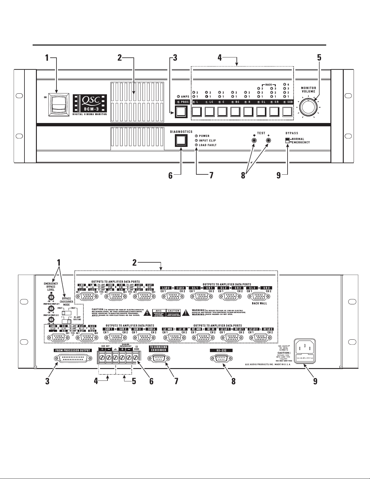
ILLUSTRATIONS- DCM-3
DCM-3 FRONT PANEL
1- Power switch
2- Monitor output speaker
3- Amplifier/Processor selector switch
4- Monitor source selector switches
5- Monitor volume control
6- Diagnostics check switch
7- Power “on” and diagnostics fault indicator LEDs
8- Monitor output test points
9- Bypass switch
DCM-3 REAR PANEL
1- Emergency bypass level controls & bypass switches
2- DataPort outputs to amplifiers
3- Audio input connector (from Cinema Processor)
4- Subwoofer output
5- Hearing Impaired system output
10
6- Surround “EX” mode remote on/off input
7- Output to Dolby Surround EX decoder
8- RS-232 port
9- IEC-style power cord entry and fuseholder
HARDWARE DESCRIPTION- Front Panel
FRONT PANEL
The front panel of the DCM series resembles traditional cinema monitor products. This provides the projectionist a well known and easy to understand interface.
Power Switch: The power on/off switch is the master control for the DCM and the amplifiers
connected to it. Amplifiers must be connected to the DCM with DataPort cables and power
switches must physically be in the “on” position. The DataPort connection to DCA amplifiers have a
standby control pin which provides standby control. QSC’s DCA amplifiers feature zero inrush
current, requiring no additional start-up sequencing. Center channel amplifier standby power
control can be bypassed using the BYPASS switch, see settings, below.
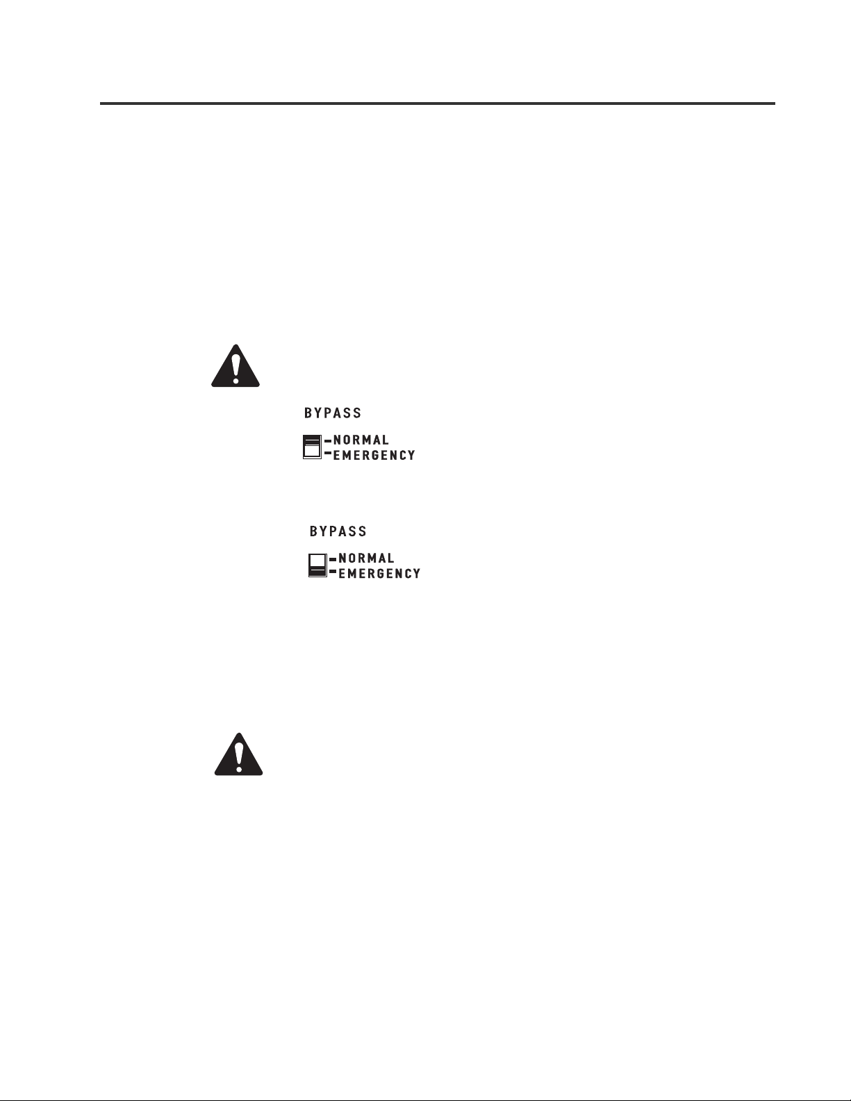
The Emergency Bypass switch setting alters the
Power Status of the Center Channel amplifier.
BYPASS switch set
to NORMAL
The Power Status of all amplifiers connected to the DCM
DataPorts will respond to the DCM power switch. When
the switch is in the ON position, all the amplifiers will be
on. When the switch is in the off position, all the amplifiers
will be in Standby mode.
BYPASS switch set
to EMERGENCY
Same as above EXCEPT that Center Channel (DataPort B
& C) will remain on even if the DCM Power switch is set
to the off position. For the DCM-1 only DataPort B
remains on.
Monitor Output Speaker: The front panel speaker provides direct monitoring of the processor and
amplifier output audio signals. The Processor/Amps and Monitor source selection switches determine what is being monitored and the Monitoring Volume control determines the speaker’s output
level.
The front panel TEST connections provide the same signal used to
drive the Monitor Speaker prior to the gain potentiometer (pre-fader).
TEST signal levels are the same level as the cinema processor output
signals (unity gain) and can be used for system calibration.
AMPS/PROC Selector Switch: The AMPS/PROC switch determines the function of the Monitor-
ing Select buttons, to the right of the AMPS/PROC switch. The LEDs directly over the PROC/AMPS
switch indicate what selected function the Monitor Select buttons will have. When the PROC LED is
illuminated, the Monitor Select buttons will select or deselect the various Cinema Processor inputs
to the DCM for monitoring. When the AMPS LED is illuminated, the Monitor Select buttons select
or deselect amplifier outputs for monitoring. After the AMPS/PROC choice has been made, the
individual channel buttons determine exactly which signals are routed to the front panel monitor
speaker.
11
 Loading...